WO2024190016A1 - ターニングセンタ - Google Patents
ターニングセンタ Download PDFInfo
- Publication number
- WO2024190016A1 WO2024190016A1 PCT/JP2023/044413 JP2023044413W WO2024190016A1 WO 2024190016 A1 WO2024190016 A1 WO 2024190016A1 JP 2023044413 W JP2023044413 W JP 2023044413W WO 2024190016 A1 WO2024190016 A1 WO 2024190016A1
- Authority
- WO
- WIPO (PCT)
- Prior art keywords
- tool
- turning
- spindle
- workpiece
- turning center
- Prior art date
- Legal status (The legal status is an assumption and is not a legal conclusion. Google has not performed a legal analysis and makes no representation as to the accuracy of the status listed.)
- Ceased
Links
Images


Classifications
-
- B—PERFORMING OPERATIONS; TRANSPORTING
- B23—MACHINE TOOLS; METAL-WORKING NOT OTHERWISE PROVIDED FOR
- B23B—TURNING; BORING
- B23B3/00—General-purpose turning-machines or devices, e.g. centre lathes with feed rod and lead screw; Sets of turning-machines
- B23B3/22—Turning-machines or devices with rotary tool heads
-
- B—PERFORMING OPERATIONS; TRANSPORTING
- B23—MACHINE TOOLS; METAL-WORKING NOT OTHERWISE PROVIDED FOR
- B23C—MILLING
- B23C7/00—Milling devices able to be attached to a machine tool, whether or not replacing an operative portion of the machine tool
- B23C7/02—Milling devices able to be attached to a machine tool, whether or not replacing an operative portion of the machine tool to lathes
-
- B—PERFORMING OPERATIONS; TRANSPORTING
- B23—MACHINE TOOLS; METAL-WORKING NOT OTHERWISE PROVIDED FOR
- B23P—METAL-WORKING NOT OTHERWISE PROVIDED FOR; COMBINED OPERATIONS; UNIVERSAL MACHINE TOOLS
- B23P23/00—Machines or arrangements of machines for performing specified combinations of different metal-working operations not covered by a single other subclass
- B23P23/02—Machine tools for performing different machining operations
Definitions
- the present invention relates to a turning center.
- Patent Document 1 discloses a turning center that can perform cutting using a rotating tool and turning using a non-rotating cutting tool.
- the turning center is equipped with an automatic tool changer that interchangeably attaches a rotating tool or a turning tool to the spindle.
- Turning centers rotate a rotating tool attached to the spindle to cut a workpiece fixed to a table. Turning centers also rotate the workpiece on the table and cut the workpiece with a turning tool attached to the spindle.
- the tool mounting position may shift in the circumferential direction of the spindle, which may result in variation in the tool mounting position.
- the cutting edge position of the turning tool will vary each time the tool is replaced, which can cause variation in the machining accuracy of the workpiece.
- the present invention was made in consideration of these technical issues, and aims to make it possible to suppress variation in processing accuracy.
- a turning center for machining a workpiece comprising: a table for supporting the workpiece; a spindle head for rotatably supporting a spindle and movable along the axial direction of the spindle toward the table; a tool changer for attaching to and detaching from the spindle a rotating tool that is rotated by the spindle to perform cutting machining; a drive for rotating the table; and a turning tool that is fixed non-rotatably to the spindle head at a position separate from the spindle and that turns the workpiece while rotating with the table.
- the rotating tool that is rotated by the spindle is attached to and detached from the spindle by the tool changer, while the turning tool that turns the rotating workpiece is fixed to the spindle head so that it cannot rotate. Therefore, compared to when the turning tool is attached to and detached from the spindle by the tool changer, the impact on the fixed position of the turning tool can be reduced even when transitioning from cutting with a rotating tool to turning with a turning tool.
- FIG. 1 is a schematic side view of a turning center according to a first embodiment.
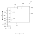
- FIG. 2 is an enlarged view showing a fixed block of a turning center.
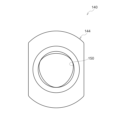
- FIG. 3 is a diagram showing an end face of the clamp unit attached to the fixed block.
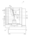
- FIG. 4 is an explanatory diagram showing a state in which a workpiece is cut by a rotary tool.
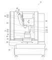
- FIG. 5 is an explanatory diagram showing a state in which a workpiece is turned by a turning tool.
- FIG. 6 is an explanatory diagram showing how the position of the cutting edge of the turning tool changes depending on the mounting state.
- FIG. 7 is a diagram showing a fixed block of a turning center according to the second embodiment.
- FIG. 1 is a schematic side view of a turning center 10 according to a first embodiment.
- FIG. 2 is an enlarged view showing a fixed block 112 of the turning center 10.
- FIG. 3 is a view showing an end face of a clamp unit 140 attached to the fixed block 112.
- the direction perpendicular to the paper surface of FIG. 1 is referred to as the X-axis direction
- the direction perpendicular to the paper surface of FIG. 2 is referred to as the Y-axis direction.
- the turning center 10 is a machine tool that processes a workpiece 12.
- the turning center 10 is capable of performing cutting using a rotating tool 80 and turning using a non-rotating tool, a turning tool 110.
- the turning center 10 has a base portion 22 having legs 20.
- a machining chamber 24 is provided on the base portion 22.
- the base portion 22 is provided with an XY table 26 that is movable in the X-axis and Y-axis directions.
- the X-axis rails that allow the XY table 26 to move in the X-axis direction and the Y-axis rails 28 that allow the XY table 26 to move in the Y-axis direction are covered by a cover not shown.
- the XY table 26 is moved in the X-axis and Y-axis directions along each rail 28 by an X-axis actuator and a Y-axis actuator not shown.
- the magnitude of acceleration and deceleration in the X-axis and Y-axis directions of the XY table 26 is determined by the specifications of the turning center 10.
- the turning center 10 of this embodiment is designed based on specifications that increase the movement efficiency of the XY table 26 in the X-axis direction, and is configured so that the acceleration and deceleration in the X-axis direction of the XY table 26 is greater than the acceleration and deceleration in the Y-axis direction.
- a driving device 30 is fixed to the XY table 26.
- the driving device 30 is composed of, for example, a motor.
- the driving device 30 directly drives and rotates the table 32.
- the table 32 can support the workpiece 12 in a fixed state.
- the table 32 is rotated by the drive unit 30, rotating the workpiece 12 fixed to the table 32.
- the workpiece 12 may be, for example, a part in which a flange 42 is formed at the end of a cylindrical portion 40.
- a flange 42 is formed at the end of a cylindrical portion 40.
- the cylindrical portion 40 or the flange 42 of the workpiece 12 is machined, and the circumferential surface of the cylindrical portion 40 is machined.
- a column 50 is provided in an upright position on the base portion 22.
- a guide rail 54 having a guide surface 52 is provided on one side of the column 50.
- the guide surface 52 extends in the Z-axis direction.
- the spindle head 60 is movably supported on the column 50.
- the spindle head 60 is guided by the guide surface 52.
- the spindle head 60 rotatably supports the spindle 62.
- the spindle 62 is rotated by a rotary actuator (not shown).
- the spindle 62 extends in the Z-axis direction, and an end of the spindle 62 protrudes from the spindle head 60 in a direction approaching the table 32.
- the spindle head 60 is moved in the Z-axis direction along the guide surface 52 by a Z-axis actuator (not shown). This allows the spindle head 60 to move in the axial direction (Z-axis direction) of the spindle 62 toward the table 32.
- a holder attachment portion 64 is provided at the end of the spindle 62 protruding from the spindle head 60.
- a tool holder 68 having a substantially conical tapered portion 66 is removably attached to the holder attachment portion 64.
- the holder attachment portion 64 has a tapered hole 70 that is generally conical and has a tapered inner surface.
- the tapered hole 70 opens to the end face of the spindle 62, and the tapered portion 66 of the tool holder 68 is inserted into the tapered hole 70.
- the holder attachment portion 64 is equipped with a clamping mechanism (not shown).
- the clamping mechanism clamps the tapered portion 66 of the tool holder 68 inserted into the tapered hole 70.
- a rotating tool 80 is fixed to the tool holder 68, and the rotating tool 80 is replaceably attached to the spindle 62 via the tool holder 68.
- the rotating tool 80 is rotated by the spindle 62 to cut the workpiece 12.
- the rotating tool 80 is composed of a drill, an end mill, a milling cutter, etc.
- a tool changer 90 is provided on the side of the spindle head 60 to attach and detach the rotating tool 80 to the spindle 62.
- the tool changer 90 includes a tool magazine 92 and a support bracket 94 that rotatably supports the tool magazine 92.
- the support bracket 94 is supported by a fixed bracket 98 provided on a beam portion 96 of the turning center 10 via a support shaft 100.
- the support bracket 94 that supports the tool magazine 92 can be tilted around the support shaft 100.
- the tool magazine 92 is formed in a disk shape, with multiple slots (not shown) provided around the outer periphery at equal intervals in the circumferential direction. Each slot holds the tool holder 68 of the rotating tool 80 in a removable manner.
- the tool magazine 92 is rotationally controlled by a motor (not shown).
- the tool magazine 92 is also tilted about the support shaft 100 by a tilting actuator (not shown).
- the tool magazine 92 In the attachment process for attaching the rotating tools 80 in the tool magazine 92 to the spindle 62, the tool magazine 92 is rotated and one of the rotating tools 80 held in the slot is moved near the end of the spindle 62. The tool magazine 92 is then tilted about the support shaft 100, and the rotating tool 80 held in the slot is positioned at the tip of the end of the spindle 62.
- the spindle head 60 is moved in the Z-axis direction, the tapered portion 66 of the tool holder 68 is inserted into the tapered hole 70 of the holder attachment portion 64 of the spindle 62, and the tool holder 68 with the rotating tool 80 is attached to the spindle 62 by the clamping mechanism.
- an empty slot in the tool magazine 92 is moved near the end of the spindle 62. Then, the tool magazine 92 is tilted about the support shaft 100, and the tool holder 68 of the rotating tool 80 attached to the spindle 62 is inserted into the empty slot in the tool magazine 92. Next, the clamping mechanism allows the tapered portion 66 of the tool holder 68 to be detached from the tapered hole 70 of the spindle 62, and the spindle head 60 is moved in the Z-axis direction to remove the rotating tool 80 from the spindle 62.
- the turning tool 110 is fixed to the spindle head 60 in a non-rotatable state.
- the turning tool 110 is fixed to the spindle head 60 via a fixed block 112 at a position separate from the spindle 62.
- the fixed block 112 fixes the turning tool 110 attached to the fixed block 112 in a non-rotatable state.
- the fixed block 112 includes a plate-shaped adapter block 120 that is bolted to the underside of the spindle head 60, and a tool insertion block 122 that is bolted to the adapter block 120.
- the adapter block 120 is positioned with a portion of it inserted into a notch 126 formed in the upper end surface 124 of the tool insertion block 122.
- the tool insertion block 122 is formed in a rectangular plate shape with its short sides extending in the Z-axis direction.
- the tool insertion block 122 has a mounting hole 130 extending in the Z-axis direction formed on one side in the longitudinal direction.
- the mounting hole 130 opens into the lower end surface 132 of the tool insertion block 122.
- Five screw holes 134 are formed on the side of the tool insertion block 122, reaching the mounting holes 130.
- the screw holes 134 are arranged in a line in the Z-axis direction.
- the distance between adjacent screw holes 134 is such that the distance RL between the screw holes 134 located on the lower end side of the tool insertion block 122 is shorter than the distance RU between the screw holes 134 located on the upper end side of the tool insertion block 122.
- the turning tool 110 is attached to the mounting hole 130 via the clamp unit 140.
- the clamp unit 140 has a small diameter insertion portion 142 that is inserted into the mounting hole 130, and a clamp portion 144 that is larger in diameter than the insertion portion 142.
- the insertion portion 142 is formed in a cylindrical shape, and a flat portion (not shown) is formed on the side of the insertion portion 142.
- the flat portion is positioned on the screw hole 134 side.
- the tip of the screw that is screwed into the screw hole 134 of the tool insertion block 122 abuts against the flat portion of the insertion portion 142. This prevents the clamp unit 140 from rotating relative to the fixed block 112.
- the clamp portion 144 of the clamp unit 140 has a tool mounting hole 150.
- the tool mounting hole 150 opens to the end face of the clamp portion 144.
- the shaft portion 152 (see FIG. 2) of the turning tool 110 is inserted into the tool mounting hole 150.
- the opening shape of the tool mounting hole 150 is non-circular, and is a triangle with a rounded apex.
- the clamping portion 144 also includes a clamping mechanism (not shown).
- the clamping mechanism clamps the shaft portion 152 of the turning tool 110 that is inserted into the tool mounting hole 150.
- the turning tool 110 turns the workpiece 12 which rotates together with the table 32.
- the turning tool 110 is composed of a cutting tool, etc.
- the cross-sectional shape of the shaft portion 152 of the turning tool 110 is non-circular, the same as the opening shape of the tool mounting hole 150 (see FIG. 3). More specifically, the cross-sectional shape of the shaft portion 152 of the turning tool 110 is a triangle with a rounded apex.
- the turning tool 110 attached to the clamp unit 140 cannot rotate relative to the clamp unit 140.
- the clamp unit 140 attached to the fixed block 112 cannot rotate relative to the fixed block 112.
- the fixed block 112 is then fixed to the spindle head 60 with bolts. Therefore, the turning tool 110 is fixed to the spindle head 60 so that it cannot rotate.
- the cutting edge 110H at the tip of the turning tool 110 is positioned closer to the spindle head 60 than the cutting section 80H where the rotating tool 80 attached to the spindle 62 cuts the workpiece 12. This ensures that the turning tool 110 fixed to the spindle head 60 does not interfere with the workpiece 12 when the rotating tool 80 attached to the spindle 62 cuts the workpiece 12.
- FIG. 4 is an explanatory diagram showing how the workpiece 12 is cut by the rotating tool 80.
- FIG. 5 is an explanatory diagram showing how the workpiece 12 is cut by the turning tool 110.
- the spindle 62 to which the rotating tool 80 is attached is rotated by a rotary actuator (not shown).
- the spindle head 60 is moved in a direction approaching the table 32 along the axial direction (Z-axis direction) of the spindle 62 by a Z-axis actuator (not shown).
- the rotating tool 80 attached to the spindle 62 is brought into contact with the workpiece 12 and cuts the workpiece 12.
- the XY table 26 is moved in the X-axis and Y-axis directions to cut the workpiece 12.
- the rotating tool 80 is removed from the spindle 62 according to the removal process described above.
- the spindle head 60 is then moved by a Z-axis actuator (not shown) along the axial direction of the spindle 62 (Z-axis direction) in a direction approaching the table 32.
- the turning tool 110 which is fixed non-rotatably to the spindle head 60 via the fixed block 112, is moved to the height position of the workpiece 12 supported by the table 32.
- the table 32 is then rotated by the driving device 30.
- the XY table 26 is also moved in the Y-axis direction by a Y-axis actuator (not shown).
- a Y-axis actuator not shown.
- a turning center 10 for machining a workpiece 12 includes a table 32 for supporting the workpiece 12, and a spindle head 60 that rotatably supports a spindle 62 and is movable along the axial direction (Z-axis direction) of the spindle 62 toward the table 32.
- the turning center 10 includes a tool changer 90 for attaching and detaching a rotating tool 80 to and from the spindle 62, which is rotated by the spindle 62 to perform cutting processing, and a drive unit 30 for rotating the table 32.
- the turning center 10 includes a turning tool 110 that is fixed non-rotatably to the spindle head 60 at a position separate from the spindle 62 and that turns the workpiece 12 rotating with the table 32.
- the rotating tool 80 rotated by the spindle 62 is attached to and detached from the spindle 62 by the tool changer 90, while the turning tool 110 that turns the rotating workpiece 12 is fixed to the spindle head 60 so that it cannot rotate.
- the effects on the fixed position of the turning tool 110 can be reduced even when transitioning from cutting using the rotating tool 80 to turning using the turning tool 110.
- Figure 6 is an explanatory diagram showing how the position of the cutting edge 110H of the turning tool 110 changes depending on the mounting state.
- the position where the cutting edge 110H of the turning tool 110 contacts the workpiece 12 differs between a first state 160 in which the turning tool 110 is attached to the spindle 62 in the correct position and a second state 162 in which the turning tool 110 is attached to the spindle 62 in a position shifted circumferentially from the correct position.
- This can cause variation in the machining accuracy of the workpiece 12 between the first state 160 and the second state 162.
- cutting processing is possible with the rotating tool 80 and turning processing is possible with the turning tool 110, while suppressing fluctuations in the cutting edge position of the turning tool 110, thereby making it possible to suppress variations in the machining accuracy of the workpiece 12.
- the turning tool 110 is fixed to the spindle head 60 via a fixed block 112.
- the turning tool 110 is fixed to the spindle head 60 via the fixing block 112, which improves workability, for example, when replacing the turning tool 110, compared to when the turning tool 110 is fixed directly to the spindle head 60.
- the fixed block 112 fixes the turning tool 110 attached to the fixed block 112 in a non-rotatable state.
- the fixed block 112 fixes the attached turning tool 110 in an unrotatable state, so that even if the attached turning tool 110 is replaced, the turning tool 110 can be placed in an unrotatable state in the correct position.
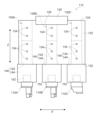
- FIG. 7 is a diagram showing the fixed block 112 of the turning center 10 according to the second embodiment.
- the turning center 10 according to this embodiment is different from the turning center 10 according to the first embodiment in the configuration of the fixed block 112 used in the turning center 10.
- the tool insertion block 122 of the fixed block 112 has a first mounting hole 130A, a second mounting hole 130B, and a third mounting hole 130C extending in the Z-axis direction and formed at equal intervals in the X-axis direction.
- Each of the mounting holes 130A to 130C opens into the lower end surface 132 of the tool insertion block 122.
- Turning tools 110A-110C are attached to each of the mounting holes 130A-130C via the clamp unit 140. This allows multiple turning tools (110A-110C) to be attached to the fixed block 112.
- a first turning tool 110A used in a first turning process is attached to the first mounting hole 130A.
- a second turning tool 110B used in a second turning process is attached to the second mounting hole 130B.
- a third turning tool 110C used in a third turning process is attached to the third mounting hole 130C.
- the turning process is carried out in the order of a first turning process, a second turning process, and a third turning process.
- the turning tools 110A to 110C used in each turning process are arranged in the order of the processes.
- the turning tools 110A to 110C are arranged at equal intervals in the X-axis direction, which is the direction of movement of the XY table 26, which is moved by an X-axis actuator (not shown).
- the turning center 10 of this embodiment is configured so that the acceleration and deceleration of the XY table 26 in the X-axis direction is greater than the acceleration and deceleration in the Y-axis direction.
- This tool insertion block 122 has a notch 126 to which the adapter block 120 is fixed, formed in the center of the length direction (X-axis direction) of the upper end surface 124. As a result, the tool insertion block 122 is fixed at its center in the length direction to the spindle head 60 via the adapter block 120.
- the tool insertion block 122 in which the turning tools 110A to 110C are arranged side by side in the X-axis direction can be supported in a well-balanced manner.
- this embodiment can provide the following actions and effects:
- each turning tool 110A to 110C used in a different turning process can be attached to a fixed block 112.
- the turning tools 110A to 110C used in each turning process are arranged in the tool insertion block 122 of the fixed block 112 in the order of the processes.
- the XY table 26 is moved sequentially in the X-axis direction, so that the workpiece 12 supported by the table 32 can be brought into contact with each of the turning tools 110A to 110C used in each cutting process in sequence.
- the efficiency of moving the workpiece 12 between each process can be improved compared to when the turning tools 110A-110C used in each turning process are arranged regardless of the order of the turning processes.
- the turning tools 110A-110C are arranged side by side in the X-axis direction on the fixed block 112. This simplifies the program processing for controlling the XY table 26 compared to a case where the turning tools 110A-110C are not arranged side by side in the X-axis direction and the XY table 26 needs to be moved in both the X-axis and Y-axis directions when performing each turning process in sequence.
- the speed at which the XY table 26, which moves the workpiece 12, moves in the X-axis direction is faster than the speed at which the XY table 26 moves in the Y-axis direction. This makes it possible to shorten the transition time between each turning process, compared to when the turning tools 110A-110C are arranged side-by-side in the Y-axis direction.
- the tool exchange device 90 is described as rotating the tool magazine 92 to exchange the rotating tool 80, but the tool exchange device 90 is not limited to this configuration.
- the tool exchange device 90 may be configured as a transport mechanism that carries the rotating tool 80 to the spindle 62.
- the spindle head 60 is described as being movable only in the Z-axis direction, but the spindle head 60 is not limited to this.
- the spindle head 60 may also be movable in the X-axis direction and the Y-axis direction.
- the turning center 10 is used to perform both cutting and turning, but the use of the turning center 10 is not limited to this.
- the turning center 10 may be used to process the workpiece 12 by only cutting, or to process the workpiece 12 by only turning.
Landscapes
- Engineering & Computer Science (AREA)
- Mechanical Engineering (AREA)
- Physics & Mathematics (AREA)
- Optics & Photonics (AREA)
- Machine Tool Units (AREA)
Abstract
[課題]加工精度のばらつきを抑制可能とする。 [解決手段]工作物を加工するターニングセンタは、工作物を支持するテーブルと、主軸を回転可能に支持するとともに当該主軸の軸方向に沿ってテーブルへ近づく方向に移動可能な主軸頭と、主軸で回動されて切削加工する回転工具を前記主軸に脱着する工具交換装置と、テーブルを回転させる駆動装置と、主軸とは別の位置において主軸頭に回転不能に固定され、テーブルと共に回転する工作物を旋削加工する旋削工具と、を備える。
Description
本発明は、ターニングセンタに関する。
特許文献1には、回転工具による切削加工及び非回転工具の旋削工具による旋削加工を行うことができるターニングセンタが開示されている。当該ターニングセンタは、主軸に回転工具又は旋削用工具を交換可能に取り付ける自動工具交換装置を備える。
ターニングセンタは、主軸に取り付けられた回転工具を回転してテーブルに固定された工作物を切削加工する。また、ターニングセンタは、テーブルで工作物を回転して主軸に取り付けられた旋削用工具で工作物を旋削加工する。
上記のターニングセンタにおいて、自動工具交換装置による工具交換を繰り返し行うと、工具の取付位置が主軸の周方向へずれることがあり、工具の取付位置にばらつきが生じ得る。
主軸に取り付けられる工具が旋削用工具の場合、工具交換する度に旋削用工具の刃先位置にばらつきが生ずることとなり、工作物の加工精度にばらつきが生じ得る。
本発明は、このような技術的課題に鑑みてなされたもので、加工精度のばらつきを抑制可能とすることを目的とする。
本発明のある態様によれば、工作物を加工するターニングセンタであって、前記工作物を支持するテーブルと、主軸を回転可能に支持するとともに当該主軸の軸方向に沿って前記テーブルへ近づく方向に移動可能な主軸頭と、前記主軸で回動されて切削加工する回転工具を前記主軸に脱着する工具交換装置と、前記テーブルを回転させる駆動装置と、前記主軸とは別の位置において前記主軸頭に回転不能に固定され、前記テーブルと共に回転する前記工作物を旋削加工する旋削工具と、を備えるターニングセンタが提供される。
本発明のある態様によれば、主軸で回動される回転工具は、工具交換装置によって主軸に脱着される一方、回転する工作物を旋削加工する旋削工具は、主軸頭に回転不能に固定される。このため、旋削工具が工具交換装置で主軸に脱着される場合と比較して、回転工具による切削加工から旋削工具による旋削加工へ移行する場合であっても、旋削工具の固定位置への影響を抑えることできる。
これにより、旋削工具の位置ずれを抑制できるので、旋削工具の刃先位置のばらつきを抑えることができ、加工精度のばらつきの抑制が可能となる。
<第一実施形態>
以下、添付図面を参照しながら本発明の第一実施形態に係るターニングセンタ10について説明する。
以下、添付図面を参照しながら本発明の第一実施形態に係るターニングセンタ10について説明する。
図1は、第一実施形態に係るターニングセンタ10の概略側面図である。図2は、ターニングセンタ10の固定ブロック112を示す拡大図である。図3は、固定ブロック112に取り付けられるクランプユニット140の端面を示す図である。なお、以下の説明においては、図1の紙面に直交する方向をX軸方向、図2の紙面に直交する方向をY軸方向と称する。
ターニングセンタ10は、工作物12を加工する工作機械である。ターニングセンタ10は、回転工具80による切削加工と非回転工具の旋削工具110による旋削加工とを行うことが可能である。
図1に示すように、ターニングセンタ10は、脚部20を有したベース部22を備える。ベース部22上には、加工室24が設けられている。
ベース部22には、X軸方向及びY軸方向へ移動可能なXYテーブル26が設けられている。XYテーブル26のX軸方向への移動を許容するX軸レール及びY軸方向への移動を許容するY軸レール28は(Y軸レール28のみ図示)、図示しないカバーによって覆われている。XYテーブル26は、図示しないX軸アクチュエータ及びY軸アクチュエータによって各レール28に沿ってX軸方向及びY軸方向へ移動される。
XYテーブル26のX軸方向及びY軸方向の加減速の大きさは、ターニングセンタ10の仕様によって定められる。本実施形態のターニングセンタ10は、XYテーブル26のX軸方向の移動効率が高まるような仕様に基づいて設計されており、XYテーブル26のX軸方向の加減速がY軸方向の加減速よりも大きくなるように構成されている。
XYテーブル26には、駆動装置30が固定されている。駆動装置30は、例えばモータで構成される。駆動装置30は、テーブル32を直接回転駆動する。
テーブル32は、工作物12を固定した状態で支持することができる。テーブル32は、駆動装置30で回動され、当該テーブル32に固定された工作物12を回転する。
工作物12としては、例えば円筒部40の端部にフランジ42が形成された部品が挙げられる。工作物12は、例えば円筒部40又はフランジ42が切削加工され、円筒部40の周面が旋削加工される。
ベース部22には、コラム50が起立した状態で設けられている。コラム50の一側面には、ガイド面52を有したガイドレール54が設けられている。ガイド面52は、Z軸方向に延びている。
コラム50には、主軸頭(スピンドルヘッド)60が移動可能に支持されている。主軸頭60は、ガイド面52に案内される。
主軸頭60は、主軸(スピンドル)62を回転可能に支持する。主軸62は、図示しない回転アクチュエータによって回転される。主軸62は、Z軸方向に延び、主軸62の端部は、主軸頭60からテーブル32へ近づく方向に突出する。
主軸頭60は、図示しないZ軸アクチュエータによってガイド面52に沿ってZ軸方向へ移動される。これにより、主軸頭60は、主軸62の軸方向(Z軸方向)に沿ってテーブル32へ近づく方向に移動可能である。
主軸頭60から突出した主軸62の端部には、ホルダ取付部64が設けられている。ホルダ取付部64には、略円錐形のテーパ部66を有する工具ホルダ68が脱着可能に取り付けられる。
ホルダ取付部64は、内面をテーパ面とした略円錐形のテーパ穴70を備える。テーパ穴70は、主軸62の端面に開口し、テーパ穴70には、工具ホルダ68のテーパ部66が挿入される。
ホルダ取付部64は、図示しないクランプ機構を備える。クランプ機構は、テーパ穴70に挿入された工具ホルダ68のテーパ部66をクランプする。
工具ホルダ68には、回転工具80が固定されており、回転工具80は、工具ホルダ68を介して主軸62に交換可能に取り付けられる。回転工具80は、主軸62で回動され、工作物12を切削加工する。回転工具80は、ドリル、エンドミル、及びフライス等で構成される。
主軸頭60の側部には、回転工具80を主軸62に脱着する工具交換装置90が設けられている。工具交換装置90は、工具マガジン92と、工具マガジン92を回転可能に支持する支持ブラケット94とを備える。支持ブラケット94は、ターニングセンタ10の梁部96に設けられた固定ブラケット98に支持軸100を介して支持される。工具マガジン92を支持する支持ブラケット94は、支持軸100を中心として傾倒可能である。
工具マガジン92は、円盤状に形成されており、外周には複数のスロット(図示省略)が周方向に等間隔に設けられている。各スロットには、回転工具80の工具ホルダ68が脱着可能に保持される。
工具マガジン92は、図示しないモータによって回転制御される。また、工具マガジン92は、図示しない傾倒アクチュエータによって支持軸100を中心に傾倒される。
工具マガジン92の回転工具80を主軸62に取り付ける取付工程では、工具マガジン92が回動され、スロットに保持されたいずれかの回転工具80が主軸62の端部の近傍に移動される。そして、工具マガジン92は、支持軸100を中心に傾倒され、スロットに保持された回転工具80が主軸62の端部の先端に配置される。
次に、主軸頭60がZ軸方向へ移動され、工具ホルダ68のテーパ部66が主軸62のホルダ取付部64のテーパ穴70に挿入されるとともに、回転工具80を有する工具ホルダ68がクランプ機構によって主軸62に取り付けられる。
また、主軸62から回転工具80を取り外す取外工程では、工具マガジン92の空スロットが主軸62の端部の近傍に移動される。そして、工具マガジン92が支持軸100を中心に傾倒され、主軸62に取り付けられた回転工具80の工具ホルダ68が工具マガジン92の空スロットに挿入される。次に、クランプ機構によって主軸62のテーパ穴70から工具ホルダ68のテーパ部66が離脱可能とされ、主軸頭60がZ軸方向へ移動されることで主軸62から回転工具80が取り外される。
主軸頭60には、旋削工具110が回転不能な状態で固定されている。旋削工具110は、主軸62とは別の位置において、固定ブロック112を介して主軸頭60に固定される。固定ブロック112は、当該固定ブロック112に取り付けられる旋削工具110を回転不能な状態で固定する。
図2に示すように、固定ブロック112は、主軸頭60の下面にボルトで固定される板状のアダプタブロック120と、アダプタブロック120にボルトで固定される工具挿入ブロック122とを備える。アダプタブロック120は、工具挿入ブロック122の上端面124に形成された切欠部126に一部が挿入された状態で位置決めされている。
工具挿入ブロック122は、長方形の板状に形成されており、短辺がZ軸方向に延在する。工具挿入ブロック122には、Z軸方向に延在する取付穴130が長さ方向の一方側に形成されている。取付穴130は、工具挿入ブロック122の下端面132に開口する。
工具挿入ブロック122の側面には、取付穴130に達するネジ穴134が五箇所に形成されている。各ネジ穴134は、Z軸方向に並んで配置されている。隣接するネジ穴134の離間距離は、工具挿入ブロック122の上端側に配置されたネジ穴134の離間距離RUよりも下端側に配置されたネジ穴134の離間距離RLが短い。
取付穴130には、クランプユニット140を介して旋削工具110が取り付けられる。
クランプユニット140は、取付穴130に挿入される小径の挿入部142と、挿入部142よりも大径のクランプ部144とを有する。挿入部142は円柱状に形成されており、挿入部142の側面には、平坦な平坦部(図示省略)が形成されている。挿入部142は、取付穴130に挿入された状態で平坦部がネジ穴134側に配置される。工具挿入ブロック122のネジ穴134にねじ込まれるネジの先端は、挿入部142の平坦部に当接される。これにより、クランプユニット140は、固定ブロック112に対する回転が抑制される。
図3に示すように、クランプユニット140のクランプ部144は、工具取付穴150を備える。工具取付穴150は、クランプ部144の端面に開口する。工具取付穴150には、旋削工具110の軸部152(図2参照)が挿入される。
工具取付穴150の開口形状は非円形状であり、工具取付穴150の開口形状は、三角形の頂部が丸められた形状である。
また、クランプ部144は、図示しないクランプ機構を備える。クランプ機構は、工具取付穴150に挿入される旋削工具110の軸部152をクランプする。
図1に示すように、旋削工具110は、テーブル32と共に回転する工作物12を旋削加工する。旋削工具110は、バイト等で構成される。
旋削工具110の軸部152の横断面形状は、工具取付穴150の開口形状と同じ非円形状である(図3参照)。具体的に説明すると、旋削工具110の軸部152の横断面形状は、三角形の頂部が丸められた形状である。
このため、クランプユニット140に取り付けられた旋削工具110は、クランプユニット140に対して回転不能である。また、固定ブロック112に取り付けられたクランプユニット140は、固定ブロック112に対して回転不能である。そして、固定ブロック112は、主軸頭60にボルトで固定される。したがって、旋削工具110は、主軸頭60に回転不能に固定される。
この旋削工具110の先端に設けられた刃先110Hは、主軸62に取り付けられた回転工具80が工作物12を切削加工する切削加工部80Hよりも、主軸頭60に近い位置に配置されている。これにより、主軸62に取り付けられた回転工具80で工作物12を切削加工する際に主軸頭60に固定された旋削工具110が工作物12と干渉しないように構成されている。
(動作説明)
次に、ターニングセンタ10を用いて工作物12を加工する動作を図面に従って説明する。
次に、ターニングセンタ10を用いて工作物12を加工する動作を図面に従って説明する。
図4は、回転工具80で工作物12を切削加工する様子を示す説明図である。図5は、旋削工具110で工作物12を旋削加工する様子を示す説明図である。
図4に示すように、ターニングセンタ10で切削加工を行う際に、例えばドリルのような穴加工を行う場合には、回転工具80が取り付けられた主軸62は、図示しない回転アクチュエータによって回動される。また、主軸頭60は、図示しないZ軸アクチュエータによって主軸62の軸方向(Z軸方向)に沿ってテーブル32へ近づく方向に移動される。これにより、主軸62に取り付けられた回転工具80は、工作物12に当てられ、工作物12を切削加工する。また、フライス加工のような面加工を行う場合には、XYテーブル26がX軸方向及びY軸方向へ移動されることによって工作物12を切削加工する。
次に、図5に示すように、ターニングセンタ10で旋削加工を行う際には、前述した取外工程に従って回転工具80が主軸62から取り外される。そして、主軸頭60は、図示しないZ軸アクチュエータによって主軸62の軸方向(Z軸方向)に沿ってテーブル32へ近づく方向に移動される。これにより、固定ブロック112を介して主軸頭60に回転不能に固定された旋削工具110は、テーブル32に支持された工作物12の高さ位置まで移動される。
そして、テーブル32は、駆動装置30によって回動される。また、XYテーブル26は、図示しないY軸アクチュエータによってY軸方向へ移動される。これにより、テーブル32と共に回転する工作物12は、旋削工具110に当てられて旋削加工される。
(作用及び効果)
以上のように構成されたターニングセンタ10の主な作用効果についてまとめて説明する。
以上のように構成されたターニングセンタ10の主な作用効果についてまとめて説明する。
(1)工作物12を加工するターニングセンタ10は、工作物12を支持するテーブル32と、主軸62を回転可能に支持するとともに当該主軸62の軸方向(Z軸方向)に沿ってテーブル32へ近づく方向に移動可能な主軸頭60と、を備える。ターニングセンタ10は、主軸62で回動されて切削加工する回転工具80を主軸62に脱着する工具交換装置90と、テーブル32を回転させる駆動装置30と、を備える。ターニングセンタ10は、主軸62とは別の位置において主軸頭60に回転不能に固定され、テーブル32と共に回転する工作物12を旋削加工する旋削工具110を備える。
本実施形態によれば、主軸62で回動される回転工具80は、工具交換装置90によって主軸62に脱着される一方、回転する工作物12を旋削加工する旋削工具110は、主軸頭60に回転不能に固定される。
このため、旋削工具110が工具交換装置90で主軸62に脱着される場合と比較して、回転工具80による切削加工から旋削工具110による旋削加工へ移行する場合であっても、旋削工具110の固定位置に生ずる影響を抑えることできる。
これにより、旋削工具110の位置ずれが抑制されるので、旋削工具110の刃先位置のばらつきを抑えることができ、工作物12の加工精度のばらつきを抑制することが可能となる。
ここで、旋削工具110の位置ずれと加工精度のばらつきとの関係について図面に従って説明する。図6は、取付状態によって旋削工具110の刃先110Hの位置が変化する様子を示す説明図である。
図1及び図6に示すように、主軸62への旋削工具110の交換を工具交換装置90によって繰り返し行うと、主軸62のホルダ取付部64と、ホルダ取付部64に取り付けられる工具ホルダ68のテーパ部66とに周方向のずれが生ずることがある。
主軸62に対して旋削工具110が正規位置に取り付けられた第一状態160と、主軸62に対して旋削工具110が正規位置から周方向へずれた位置に取り付けられた第二状態162とでは、駆動装置30によってテーブル32を回転させて旋削加工を行う場合、旋削工具110の刃先110Hが工作物12に当たる位置が異なる。これにより、第一状態160と第二状態162とでは、工作物12の加工精度にばらつきが生じ得る。
しかしながら、本実施形態のターニングセンタ10にあっては、回転工具80による切削加工と旋削工具110による旋削加工とを可能としつつ、旋削工具110の刃先位置の変動を抑えることで、工作物12の加工精度のばらつきの抑制が可能となる。
(2)旋削工具110は、固定ブロック112を介して主軸頭60に固定される。
本実施形態によれば、旋削工具110は、固定ブロック112を介して主軸頭60に固定されるので、旋削工具110を直接主軸頭60に固定する場合と比較して、例えば旋削工具110を交換する際の作業性が向上する。
(3)固定ブロック112は、当該固定ブロック112に取り付けられる旋削工具110を回転不能な状態で固定する。
本実施形態によれば、固定ブロック112は、取り付けられる旋削工具110を回転不能な状態で固定するため、取り付けられた旋削工具110を交換した場合であっても、旋削工具110を正規位置において回転不能な状態とすることができる。
これにより、旋削工具110を交換可能としつつ、旋削工具110の位置ずれに起因した加工精度のばらつきを抑制することが可能となる。
<第二実施形態>
次に、本発明の第二実施形態に係るターニングセンタ10について添付図面を参照しながら説明する。本実施形態において第一実施形態と同一又は同等部分については、同符号を付して説明を割愛するとともに、第一実施形態と異なる部分について説明する。
次に、本発明の第二実施形態に係るターニングセンタ10について添付図面を参照しながら説明する。本実施形態において第一実施形態と同一又は同等部分については、同符号を付して説明を割愛するとともに、第一実施形態と異なる部分について説明する。
図7は、第二実施形態に係るターニングセンタ10の固定ブロック112を示す図である。本実施形態に係るターニングセンタ10は、第一実施形態のターニングセンタ10と比較して、ターニングセンタ10で用いられる固定ブロック112の構成が異なる。
図7に示すように、本実施形態の固定ブロック112の工具挿入ブロック122には、Z軸方向に延在する第一取付穴130A、第二取付穴130B、及び第三取付穴130CがX軸方向に等間隔をおいて形成されている。各取付穴130A~130Cは、工具挿入ブロック122の下端面132に開口する。
各取付穴130A~130Cには、クランプユニット140を介して、旋削工具110A~110Cが取り付けされる。これにより、固定ブロック112には、複数の旋削工具(110A~110C)が取り付けられる。
具体的に説明すると、第一取付穴130Aには、第一旋削工程で用いられる第一旋削工具110Aが取り付けられる。第二取付穴130Bには、第二旋削工程で用いられる第二旋削工具110Bが取り付けられる。また、第三取付穴130Cには、第三旋削工程で用いられる第三旋削工具110Cが取り付けられる。
旋削加工は、第一旋削工程、第二旋削工程、及び第三旋削工程の順に行われる。各旋削工程で用いられる各旋削工具110A~110Cは、工程順に並んで配置される。
各旋削工具110A~110Cは、図示しないX軸アクチュエータによって移動されるXYテーブル26の移動方向であるX軸方向に等間隔をおいて並んで配置されている。また、本実施形態のターニングセンタ10は、前述したようにXYテーブル26のX軸方向の加減速がY軸方向の加減速よりも大きくなるように構成されている。
この工具挿入ブロック122には、アダプタブロック120が固定される切欠部126が、上端面124の長さ方向(X軸方向)の中央部に形成されている。これにより、工具挿入ブロック122は、長さ方向の中央部がアダプタブロック120を介して主軸頭60に固定される。
このため、工具挿入ブロック122の長さ方向の一端部がアダプタブロック120を介して主軸頭60に支持される場合と比較して、各旋削工具110A~110CがX軸方向に並んで配置された工具挿入ブロック122をバランス良く支持することができる。
(作用及び効果)
本実施形態に係るターニングセンタ10においても、第一実施形態と同一又は同等部分については、第一実施形態と同様の作用効果を奏することができる。
本実施形態に係るターニングセンタ10においても、第一実施形態と同一又は同等部分については、第一実施形態と同様の作用効果を奏することができる。
また、本実施形態では次のような作用及び効果を奏することができる。
(4)固定ブロック112には、旋削工具(110A~110C)が複数取り付けられる。
本実施形態によれば、異なる旋削工程で用いられる各旋削工具110A~110Cを固定ブロック112に取り付けることができる。
これにより、異なる旋削工具110A~110Cを用いる旋削加工を連続して行うことができる。このため、旋削工程を変更する度にターニングセンタ10を停止して各旋削工具110A~110Cを交換しなければならない場合と比較して、作業効率の向上が可能となる。
そして、本実施形態において、固定ブロック112の工具挿入ブロック122には、各旋削工程で用いられる各旋削工具110A~110Cが工程順に並んで配置されている。
このため、各旋削工程を順に行う際に、XYテーブル26をX軸方向へ順次移動することで、テーブル32に支持された工作物12を、各切削工程で用いられる各旋削工具110A~110Cに順に当接することができる。
よって、各旋削工程で用いられる各旋削工具110A~110Cが旋削工程の順番と無関係に配置される場合と比較して、各工程間での工作物12の移動効率を高めることができる。
また、本実施形態において、固定ブロック112には、各旋削工具110A~110CがX軸方向に並んで配置されている。このため、各旋削工具110A~110CがX軸方向に並んで配置されておらず、各旋削工程を順に行う際に、XYテーブル26をX軸方向及びY軸方向に移動する必要がある場合と比較して、XYテーブル26を制御する為のプログラム処理の簡素化が可能となる。
そして、本実施形態のターニングセンタ10は、工作物12を移動するXYテーブル26をX軸方向へ移動する移動速度が、XYテーブル26をY軸方向へ移動する移動速度よりも速い。このため、各旋削工具110A~110CがY軸方向に並んで配置される場合と比較して、各旋削工程間の移行時間の短縮が可能となる。
以上、本発明の実施形態について説明したが、上記実施形態は本発明の適用例の一部を示したに過ぎず、本発明の技術的範囲を上記実施形態の具体的構成に限定する趣旨ではない。
上記実施形態では、工具マガジン92を回動して回転工具80を交換する工具交換装置90を例に挙げて説明したが、工具交換装置90は、この構成に限定されるものではない。例えば工具交換装置90は、回転工具80を主軸62へ運ぶ搬送機構によって構成してもよい。
上記実施形態では、主軸頭60がZ軸方向のみに移動可能な場合について説明したが、主軸頭60は、これに限定されるものでない。例えば主軸頭60は、さらにX軸方向及びY軸方向へ移動可能なものであってもよい。
また、上記実施形態では、ターニングセンタ10によって切削加工及び旋削加工の両者を行う場合を例に挙げて説明したが、ターニングセンタ10の利用形態は、これに限定されるものではない。ターニングセンタ10は、切削加工のみを行う工作物12の加工、又は旋削加工のみを行う工作物12の加工に使用してもよい。
10 ターニングセンタ
12 工作物
30 駆動装置
32 テーブル
60 主軸頭
62 主軸
80 回転工具
90 工具交換装置
110 旋削工具
110A 第一旋削工具
110B 第二旋削工具
110C 第三旋削工具
110H 刃先
112 固定ブロック
12 工作物
30 駆動装置
32 テーブル
60 主軸頭
62 主軸
80 回転工具
90 工具交換装置
110 旋削工具
110A 第一旋削工具
110B 第二旋削工具
110C 第三旋削工具
110H 刃先
112 固定ブロック
Claims (4)
- 工作物を加工するターニングセンタであって、
前記工作物を支持するテーブルと、
主軸を回転可能に支持するとともに当該主軸の軸方向に沿って前記テーブルへ近づく方向に移動可能な主軸頭と、
前記主軸で回動されて切削加工する回転工具を前記主軸に脱着する工具交換装置と、
前記テーブルを回転させる駆動装置と、
前記主軸とは別の位置において前記主軸頭に回転不能に固定され、前記テーブルと共に回転する前記工作物を旋削加工する旋削工具と、
を備えるターニングセンタ。 - 請求項1に記載のターニングセンタであって、
前記旋削工具は、固定ブロックを介して前記主軸頭に固定される、
ターニングセンタ。 - 請求項2に記載のターニングセンタであって、
前記固定ブロックは、当該固定ブロックに取り付けられる前記旋削工具を回転不能な状態で固定する、
ターニングセンタ。 - 請求項2又は請求項3に記載のターニングセンタであって、
前記固定ブロックには、前記旋削工具が複数取り付けられる、
ターニングセンタ。
Priority Applications (1)
| Application Number | Priority Date | Filing Date | Title |
|---|---|---|---|
| JP2025506483A JPWO2024190016A1 (ja) | 2023-03-16 | 2023-12-12 |
Applications Claiming Priority (2)
| Application Number | Priority Date | Filing Date | Title |
|---|---|---|---|
| JP2023-042037 | 2023-03-16 | ||
| JP2023042037 | 2023-03-16 |
Publications (1)
| Publication Number | Publication Date |
|---|---|
| WO2024190016A1 true WO2024190016A1 (ja) | 2024-09-19 |
Family
ID=92754746
Family Applications (1)
| Application Number | Title | Priority Date | Filing Date |
|---|---|---|---|
| PCT/JP2023/044413 Ceased WO2024190016A1 (ja) | 2023-03-16 | 2023-12-12 | ターニングセンタ |
Country Status (2)
| Country | Link |
|---|---|
| JP (1) | JPWO2024190016A1 (ja) |
| WO (1) | WO2024190016A1 (ja) |
Cited By (1)
| Publication number | Priority date | Publication date | Assignee | Title |
|---|---|---|---|---|
| US20240286199A1 (en) * | 2023-02-28 | 2024-08-29 | Fives Giddings & Lewis, Llc | Adjacent turning and milling tool mount |
Citations (2)
| Publication number | Priority date | Publication date | Assignee | Title |
|---|---|---|---|---|
| JP2012210681A (ja) * | 2011-03-31 | 2012-11-01 | Brother Industries Ltd | 工作機械 |
| JP2016153149A (ja) * | 2015-02-20 | 2016-08-25 | ファナック株式会社 | 旋削工具ホルダ装着ユニットを備えた工作機械 |
Family Cites Families (1)
| Publication number | Priority date | Publication date | Assignee | Title |
|---|---|---|---|---|
| JP7424899B2 (ja) * | 2020-04-17 | 2024-01-30 | ファナック株式会社 | 傾斜調整システム |
-
2023
- 2023-12-12 WO PCT/JP2023/044413 patent/WO2024190016A1/ja not_active Ceased
- 2023-12-12 JP JP2025506483A patent/JPWO2024190016A1/ja active Pending
Patent Citations (2)
| Publication number | Priority date | Publication date | Assignee | Title |
|---|---|---|---|---|
| JP2012210681A (ja) * | 2011-03-31 | 2012-11-01 | Brother Industries Ltd | 工作機械 |
| JP2016153149A (ja) * | 2015-02-20 | 2016-08-25 | ファナック株式会社 | 旋削工具ホルダ装着ユニットを備えた工作機械 |
Cited By (1)
| Publication number | Priority date | Publication date | Assignee | Title |
|---|---|---|---|---|
| US20240286199A1 (en) * | 2023-02-28 | 2024-08-29 | Fives Giddings & Lewis, Llc | Adjacent turning and milling tool mount |
Also Published As
| Publication number | Publication date |
|---|---|
| JPWO2024190016A1 (ja) | 2024-09-19 |
Similar Documents
| Publication | Publication Date | Title |
|---|---|---|
| US9162289B2 (en) | Machine tool apparatus and method | |
| US5020201A (en) | Machine tool | |
| JP5722534B2 (ja) | 複数のワークピーススピンドルを備えた多軸旋盤 | |
| JP2010052068A (ja) | 立形工作機械 | |
| TW201916954A (zh) | 車床 | |
| JP2010064243A6 (ja) | 複数のワークピーススピンドルを備えた多軸旋盤 | |
| WO2024190016A1 (ja) | ターニングセンタ | |
| JP5611691B2 (ja) | 工作機械およびワーク加工方法 | |
| JP2005088162A (ja) | マシニングセンタ | |
| US20160368060A1 (en) | Machine tool | |
| JP3038083B2 (ja) | レーザ加工機におけるノズル交換装置 | |
| JP3040766B2 (ja) | 主軸交換手段付き工作機械及び主軸交換方法 | |
| JP2001018101A (ja) | 主軸移動型自動旋盤、そのための支持ユニットそして位置決め治具 | |
| JPH0592301A (ja) | 工作機械 | |
| JP5149031B2 (ja) | 工作機械 | |
| JP2012206178A (ja) | 回転テーブル装置及び工作機械 | |
| JP2008531300A (ja) | ドリル又はドリルビット製造用のトランスファ・マシン | |
| JP7464816B2 (ja) | 旋盤、及び、そのガイド部材取り付け方法 | |
| JP2012161904A (ja) | 複合工具、加工方法および工作機械 | |
| US20240307975A1 (en) | Tool holder and tool rest for machine tool | |
| WO2023112134A1 (ja) | 工作機械 | |
| WO2021210522A1 (ja) | 工作機械 | |
| JP2002283103A (ja) | 主軸移動型自動旋盤 | |
| JP7655816B2 (ja) | 工作機械 | |
| JP3910847B2 (ja) | 小型高速nc旋盤 |
Legal Events
| Date | Code | Title | Description |
|---|---|---|---|
| 121 | Ep: the epo has been informed by wipo that ep was designated in this application |
Ref document number: 23926631 Country of ref document: EP Kind code of ref document: A1 |
|
| WWE | Wipo information: entry into national phase |
Ref document number: 2025506483 Country of ref document: JP |
|
| NENP | Non-entry into the national phase |
Ref country code: DE |
|
| 122 | Ep: pct application non-entry in european phase |
Ref document number: 23926631 Country of ref document: EP Kind code of ref document: A1 |