WO2024189972A1 - 亜鉛二次電池 - Google Patents
亜鉛二次電池 Download PDFInfo
- Publication number
- WO2024189972A1 WO2024189972A1 PCT/JP2023/040403 JP2023040403W WO2024189972A1 WO 2024189972 A1 WO2024189972 A1 WO 2024189972A1 JP 2023040403 W JP2023040403 W JP 2023040403W WO 2024189972 A1 WO2024189972 A1 WO 2024189972A1
- Authority
- WO
- WIPO (PCT)
- Prior art keywords
- secondary battery
- zinc secondary
- negative electrode
- positive electrode
- zinc
- Prior art date
- Legal status (The legal status is an assumption and is not a legal conclusion. Google has not performed a legal analysis and makes no representation as to the accuracy of the status listed.)
- Ceased
Links
Images









Classifications
-
- H—ELECTRICITY
- H01—ELECTRIC ELEMENTS
- H01M—PROCESSES OR MEANS, e.g. BATTERIES, FOR THE DIRECT CONVERSION OF CHEMICAL ENERGY INTO ELECTRICAL ENERGY
- H01M10/00—Secondary cells; Manufacture thereof
- H01M10/24—Alkaline accumulators
- H01M10/28—Construction or manufacture
-
- H—ELECTRICITY
- H01—ELECTRIC ELEMENTS
- H01M—PROCESSES OR MEANS, e.g. BATTERIES, FOR THE DIRECT CONVERSION OF CHEMICAL ENERGY INTO ELECTRICAL ENERGY
- H01M10/00—Secondary cells; Manufacture thereof
- H01M10/24—Alkaline accumulators
- H01M10/30—Nickel accumulators
-
- H—ELECTRICITY
- H01—ELECTRIC ELEMENTS
- H01M—PROCESSES OR MEANS, e.g. BATTERIES, FOR THE DIRECT CONVERSION OF CHEMICAL ENERGY INTO ELECTRICAL ENERGY
- H01M12/00—Hybrid cells; Manufacture thereof
- H01M12/08—Hybrid cells; Manufacture thereof composed of a half-cell of a fuel-cell type and a half-cell of the secondary-cell type
-
- H—ELECTRICITY
- H01—ELECTRIC ELEMENTS
- H01M—PROCESSES OR MEANS, e.g. BATTERIES, FOR THE DIRECT CONVERSION OF CHEMICAL ENERGY INTO ELECTRICAL ENERGY
- H01M4/00—Electrodes
- H01M4/02—Electrodes composed of, or comprising, active material
- H01M4/24—Electrodes for alkaline accumulators
-
- H—ELECTRICITY
- H01—ELECTRIC ELEMENTS
- H01M—PROCESSES OR MEANS, e.g. BATTERIES, FOR THE DIRECT CONVERSION OF CHEMICAL ENERGY INTO ELECTRICAL ENERGY
- H01M4/00—Electrodes
- H01M4/02—Electrodes composed of, or comprising, active material
- H01M4/36—Selection of substances as active materials, active masses, active liquids
- H01M4/38—Selection of substances as active materials, active masses, active liquids of elements or alloys
-
- H—ELECTRICITY
- H01—ELECTRIC ELEMENTS
- H01M—PROCESSES OR MEANS, e.g. BATTERIES, FOR THE DIRECT CONVERSION OF CHEMICAL ENERGY INTO ELECTRICAL ENERGY
- H01M4/00—Electrodes
- H01M4/02—Electrodes composed of, or comprising, active material
- H01M4/36—Selection of substances as active materials, active masses, active liquids
- H01M4/38—Selection of substances as active materials, active masses, active liquids of elements or alloys
- H01M4/42—Alloys based on zinc
-
- H—ELECTRICITY
- H01—ELECTRIC ELEMENTS
- H01M—PROCESSES OR MEANS, e.g. BATTERIES, FOR THE DIRECT CONVERSION OF CHEMICAL ENERGY INTO ELECTRICAL ENERGY
- H01M4/00—Electrodes
- H01M4/02—Electrodes composed of, or comprising, active material
- H01M4/36—Selection of substances as active materials, active masses, active liquids
- H01M4/48—Selection of substances as active materials, active masses, active liquids of inorganic oxides or hydroxides
-
- H—ELECTRICITY
- H01—ELECTRIC ELEMENTS
- H01M—PROCESSES OR MEANS, e.g. BATTERIES, FOR THE DIRECT CONVERSION OF CHEMICAL ENERGY INTO ELECTRICAL ENERGY
- H01M50/00—Constructional details or processes of manufacture of the non-active parts of electrochemical cells other than fuel cells, e.g. hybrid cells
- H01M50/10—Primary casings; Jackets or wrappings
- H01M50/102—Primary casings; Jackets or wrappings characterised by their shape or physical structure
- H01M50/103—Primary casings; Jackets or wrappings characterised by their shape or physical structure prismatic or rectangular
-
- H—ELECTRICITY
- H01—ELECTRIC ELEMENTS
- H01M—PROCESSES OR MEANS, e.g. BATTERIES, FOR THE DIRECT CONVERSION OF CHEMICAL ENERGY INTO ELECTRICAL ENERGY
- H01M50/00—Constructional details or processes of manufacture of the non-active parts of electrochemical cells other than fuel cells, e.g. hybrid cells
- H01M50/10—Primary casings; Jackets or wrappings
- H01M50/147—Lids or covers
- H01M50/148—Lids or covers characterised by their shape
- H01M50/15—Lids or covers characterised by their shape for prismatic or rectangular cells
-
- H—ELECTRICITY
- H01—ELECTRIC ELEMENTS
- H01M—PROCESSES OR MEANS, e.g. BATTERIES, FOR THE DIRECT CONVERSION OF CHEMICAL ENERGY INTO ELECTRICAL ENERGY
- H01M50/00—Constructional details or processes of manufacture of the non-active parts of electrochemical cells other than fuel cells, e.g. hybrid cells
- H01M50/10—Primary casings; Jackets or wrappings
- H01M50/172—Arrangements of electric connectors penetrating the casing
- H01M50/174—Arrangements of electric connectors penetrating the casing adapted for the shape of the cells
- H01M50/176—Arrangements of electric connectors penetrating the casing adapted for the shape of the cells for prismatic or rectangular cells
-
- H—ELECTRICITY
- H01—ELECTRIC ELEMENTS
- H01M—PROCESSES OR MEANS, e.g. BATTERIES, FOR THE DIRECT CONVERSION OF CHEMICAL ENERGY INTO ELECTRICAL ENERGY
- H01M50/00—Constructional details or processes of manufacture of the non-active parts of electrochemical cells other than fuel cells, e.g. hybrid cells
- H01M50/10—Primary casings; Jackets or wrappings
- H01M50/183—Sealing members
- H01M50/184—Sealing members characterised by their shape or structure
-
- H—ELECTRICITY
- H01—ELECTRIC ELEMENTS
- H01M—PROCESSES OR MEANS, e.g. BATTERIES, FOR THE DIRECT CONVERSION OF CHEMICAL ENERGY INTO ELECTRICAL ENERGY
- H01M50/00—Constructional details or processes of manufacture of the non-active parts of electrochemical cells other than fuel cells, e.g. hybrid cells
- H01M50/10—Primary casings; Jackets or wrappings
- H01M50/183—Sealing members
- H01M50/186—Sealing members characterised by the disposition of the sealing members
- H01M50/188—Sealing members characterised by the disposition of the sealing members the sealing members being arranged between the lid and terminal
-
- H—ELECTRICITY
- H01—ELECTRIC ELEMENTS
- H01M—PROCESSES OR MEANS, e.g. BATTERIES, FOR THE DIRECT CONVERSION OF CHEMICAL ENERGY INTO ELECTRICAL ENERGY
- H01M50/00—Constructional details or processes of manufacture of the non-active parts of electrochemical cells other than fuel cells, e.g. hybrid cells
- H01M50/40—Separators; Membranes; Diaphragms; Spacing elements inside cells
- H01M50/409—Separators, membranes or diaphragms characterised by the material
- H01M50/431—Inorganic material
- H01M50/434—Ceramics
-
- H—ELECTRICITY
- H01—ELECTRIC ELEMENTS
- H01M—PROCESSES OR MEANS, e.g. BATTERIES, FOR THE DIRECT CONVERSION OF CHEMICAL ENERGY INTO ELECTRICAL ENERGY
- H01M50/00—Constructional details or processes of manufacture of the non-active parts of electrochemical cells other than fuel cells, e.g. hybrid cells
- H01M50/40—Separators; Membranes; Diaphragms; Spacing elements inside cells
- H01M50/409—Separators, membranes or diaphragms characterised by the material
- H01M50/446—Composite material consisting of a mixture of organic and inorganic materials
-
- H—ELECTRICITY
- H01—ELECTRIC ELEMENTS
- H01M—PROCESSES OR MEANS, e.g. BATTERIES, FOR THE DIRECT CONVERSION OF CHEMICAL ENERGY INTO ELECTRICAL ENERGY
- H01M50/00—Constructional details or processes of manufacture of the non-active parts of electrochemical cells other than fuel cells, e.g. hybrid cells
- H01M50/40—Separators; Membranes; Diaphragms; Spacing elements inside cells
- H01M50/409—Separators, membranes or diaphragms characterised by the material
- H01M50/449—Separators, membranes or diaphragms characterised by the material having a layered structure
-
- H—ELECTRICITY
- H01—ELECTRIC ELEMENTS
- H01M—PROCESSES OR MEANS, e.g. BATTERIES, FOR THE DIRECT CONVERSION OF CHEMICAL ENERGY INTO ELECTRICAL ENERGY
- H01M50/00—Constructional details or processes of manufacture of the non-active parts of electrochemical cells other than fuel cells, e.g. hybrid cells
- H01M50/40—Separators; Membranes; Diaphragms; Spacing elements inside cells
- H01M50/463—Separators, membranes or diaphragms characterised by their shape
- H01M50/466—U-shaped, bag-shaped or folded
-
- H—ELECTRICITY
- H01—ELECTRIC ELEMENTS
- H01M—PROCESSES OR MEANS, e.g. BATTERIES, FOR THE DIRECT CONVERSION OF CHEMICAL ENERGY INTO ELECTRICAL ENERGY
- H01M50/00—Constructional details or processes of manufacture of the non-active parts of electrochemical cells other than fuel cells, e.g. hybrid cells
- H01M50/50—Current conducting connections for cells or batteries
- H01M50/531—Electrode connections inside a battery casing
- H01M50/533—Electrode connections inside a battery casing characterised by the shape of the leads or tabs
-
- H—ELECTRICITY
- H01—ELECTRIC ELEMENTS
- H01M—PROCESSES OR MEANS, e.g. BATTERIES, FOR THE DIRECT CONVERSION OF CHEMICAL ENERGY INTO ELECTRICAL ENERGY
- H01M50/00—Constructional details or processes of manufacture of the non-active parts of electrochemical cells other than fuel cells, e.g. hybrid cells
- H01M50/50—Current conducting connections for cells or batteries
- H01M50/531—Electrode connections inside a battery casing
- H01M50/54—Connection of several leads or tabs of plate-like electrode stacks, e.g. electrode pole straps or bridges
-
- H—ELECTRICITY
- H01—ELECTRIC ELEMENTS
- H01M—PROCESSES OR MEANS, e.g. BATTERIES, FOR THE DIRECT CONVERSION OF CHEMICAL ENERGY INTO ELECTRICAL ENERGY
- H01M50/00—Constructional details or processes of manufacture of the non-active parts of electrochemical cells other than fuel cells, e.g. hybrid cells
- H01M50/50—Current conducting connections for cells or batteries
- H01M50/543—Terminals
- H01M50/547—Terminals characterised by the disposition of the terminals on the cells
- H01M50/55—Terminals characterised by the disposition of the terminals on the cells on the same side of the cell
-
- H—ELECTRICITY
- H01—ELECTRIC ELEMENTS
- H01M—PROCESSES OR MEANS, e.g. BATTERIES, FOR THE DIRECT CONVERSION OF CHEMICAL ENERGY INTO ELECTRICAL ENERGY
- H01M50/00—Constructional details or processes of manufacture of the non-active parts of electrochemical cells other than fuel cells, e.g. hybrid cells
- H01M50/50—Current conducting connections for cells or batteries
- H01M50/543—Terminals
- H01M50/552—Terminals characterised by their shape
- H01M50/553—Terminals adapted for prismatic, pouch or rectangular cells
-
- H—ELECTRICITY
- H01—ELECTRIC ELEMENTS
- H01M—PROCESSES OR MEANS, e.g. BATTERIES, FOR THE DIRECT CONVERSION OF CHEMICAL ENERGY INTO ELECTRICAL ENERGY
- H01M50/00—Constructional details or processes of manufacture of the non-active parts of electrochemical cells other than fuel cells, e.g. hybrid cells
- H01M50/50—Current conducting connections for cells or batteries
- H01M50/543—Terminals
- H01M50/564—Terminals characterised by their manufacturing process
Definitions
- the present invention relates to a zinc secondary battery.
- Patent Document 1 discloses a zinc secondary battery equipped with a stack including a positive electrode plate and a negative electrode plate, a positive electrode current collector tab connected to the positive electrode current collector and protruding upward from the stack, and a negative electrode current collector tab connected to the negative electrode current collector and protruding upward from the stack.
- Patent Document 2 discloses a secondary battery including a laminate including a positive electrode plate and a negative electrode plate, a case for accommodating the laminate, and a lid for closing the opening of the case.
- the lid includes a lid body, a terminal penetrating the lid body, a first O-ring sandwiched between the lid body and the terminal and generating a repulsive force in a first direction, and a second O-ring sandwiched between the lid body and the terminal and generating a repulsive force in a second direction.
- the first imaginary surface extending from the first O-ring in the first direction and the second imaginary surface extending from the second O-ring in the second direction do not coincide with each other. This makes it possible to prevent the repulsive forces generated in the first O-ring and the second O-ring from being applied to the lid body in a superimposed manner. This reduces the stress applied to the lid body, reduces deformation of the lid body, and strengthens the seal between the lid body and the terminal.
- Patent Document 5 (WO2019/069760) and Patent Document 6 (WO2019/077953) propose a zinc secondary battery in which the entire negative electrode active material layer is covered or wrapped with a liquid-retaining member and an LDH separator, and the positive electrode active material layer is covered or wrapped with a liquid-retaining member.
- a nonwoven fabric is used as the liquid-retaining member.
- LDH-like compounds are known as hydroxides and/or oxides having a layered crystal structure similar to LDH, and exhibit hydroxide ion conductive properties similar enough to be collectively referred to as hydroxide ion conductive layered compounds together with LDH (see, for example, Patent Documents 1 and 2).
- Patent Document 7 discloses a hydroxide ion conductive separator comprising a porous substrate and a layered double hydroxide (LDH)-like compound that blocks the pores of the porous substrate, in which the LDH-like compound is a hydroxide and/or oxide having a layered crystal structure containing Mg and one or more elements including at least Ti selected from the group consisting of Ti, Y, and Al.
- Patent Document 8 discloses an LDH separator using an LDH-like compound containing (i) Ti, Y, and optionally Al and/or Mg, and (ii) an additive element M which is at least one selected from the group consisting of In, Bi, Ca, Sr and Ba.
- Patent Document 9 discloses an LDH separator containing a mixture of an LDH-like compound and In(OH) 3 , in which the LDH-like compound is a hydroxide and/or oxide having a layered crystal structure containing Mg, Ti, Y, and optionally Al and/or In. According to the separators disclosed in Patent Documents 7 to 9, it is said that the separators have excellent alkali resistance compared to conventional LDH separators, and can more effectively suppress short circuits caused by zinc dendrites.
- Patent Document 2 proposes a structure including a lid body, a terminal penetrating the lid body, and a first O-ring and a second O-ring sandwiched between the lid body and the terminal.
- this terminal since this terminal has a complex shape, its manufacture requires many steps, and therefore the manufacturing cost is high.
- the weight of the stacked cell 112 deforms the components such as the upper cover 116, and the positive electrode upper current collector plate 130p and the negative electrode upper current collector plate 130n tilt downward toward the center of the battery.
- the compression of the O-rings 126 and 128, which are sealing members becomes insufficient at the outer parts (dotted parts in the figure) of the positive electrode terminal 118p or the negative electrode terminal 118n, and the liquid-tightness at those parts decreases. As a result, leakage is likely to occur from the insufficiently compressed parts.
- the inventors have now discovered that in a terminal sealing structure for a zinc secondary battery using an upper tab current collection method, in which two O-rings are inserted, by arranging the joint between the electrode terminal and the tab lead of the upper current collector plate, and the convex portion that provides a fulcrum on the back surface of the upper cover so as to satisfy a specified positional relationship, it is possible to effectively delay leakage due to creep from the terminal sealing structure while using a simple terminal that can be manufactured by pressing.
- the object of the present invention is therefore to provide a zinc secondary battery with an upper tab current collection system that employs simple terminals that can be manufactured by pressing, while still effectively delaying leakage caused by creep from the terminal sealing structure.
- a zinc secondary battery comprising:
- the leakage suppressing current collecting structure is - a stepped hole as a through hole having at least three stages including a large diameter hole, a medium diameter hole, and a small diameter hole in this order from the front surface to the back surface of the upper cover; a first O-ring arranged in the step formed by the large diameter hole and the medium diameter hole; a second O-ring arranged in the step formed by the medium diameter hole and the small diameter hole; - the electrode terminal
- Aspect 2 The zinc secondary battery of claim 1, wherein the ratio of b/a is 0.90 to 1.50.
- Aspect 3 The zinc secondary battery according to aspect 1 or 2, wherein a distance a between the central axis A1 and the central axis A2 is 10 to 40 mm.
- Aspect 4 The zinc secondary battery according to any one of aspects 1 to 3, wherein the distance b between the central axis A1 and the central axis A3 is 10 to 40 mm.
- Aspect 5 The zinc secondary battery according to any one of aspects 1 to 4, wherein the electrode terminal is a pressed product having a three-stage structure composed of the large diameter portion, the medium diameter portion, and the small diameter portion.
- the laminated cell is A plurality of positive electrode plates including a positive electrode active material layer and a positive electrode current collector; a plurality of positive electrode tab leads extending from each end of the positive electrode plate; a plurality of negative electrode plates including a negative electrode active material layer including at least one selected from the group consisting of zinc, zinc oxide, a zinc alloy, and a zinc compound, and a negative electrode current collector; a plurality of negative electrode tab leads extending from each end of the negative electrode plate at positions not overlapping with the positive electrode tab leads; a plurality of hydroxide ion conductive separators isolating the positive electrode plates and the negative electrode plates so as to be capable of conducting hydroxide ions; An electrolyte; The positive electrode plate and the negative electrode plate are alternately laminated with the hydroxide ion conductive separator interposed therebetween,
- the zinc secondary battery is described in any one of aspects 1 to 6, wherein the zinc secondary battery has two of the leakage suppression current collecting structures positioned on opposite sides of each other, and an
- FIG. 1 is a schematic cross-sectional view showing an example of a zinc secondary battery according to the present invention.
- FIG. 2 is a schematic diagram showing a cross section of the zinc secondary battery shown in FIG. 1 taken along line A-A'.
- FIG. 2 is a schematic cross-sectional view showing an example of a leakage suppression current collecting structure in a zinc secondary battery according to the present invention.
- 5 is a schematic cross-sectional view for explaining the action of forces in an example of a leakage-preventing current collecting structure.
- FIG. 5 is a schematic cross-sectional view for explaining the action of force on the electrode terminal of the leakage-preventing current collecting structure shown in FIG. 4 and in the vicinity thereof.
- FIG. 5 is a perspective view of the leakage suppressing current collecting structure shown in FIG.
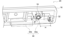
- FIG. 3 is a schematic cross-sectional view for explaining the definitions of central axes A 1 , A 2 and A 3 and distances a and b in the leakage-suppressing current collecting structure.
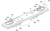
- FIG. FIG. 2 is a perspective view showing an example of a leakage suppression current collecting structure used in the zinc secondary battery of the present invention.
- 9 is a perspective view of the leakage suppressing current collecting structure shown in FIG. 8 as viewed from the rear surface side of the upper cover.
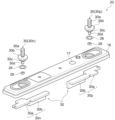
- FIG. 9 is an exploded perspective view of the leakage-preventing current collecting structure shown in FIG. 8 .
- 9 is a cross-sectional view of the leakage suppressing current collecting structure shown in FIG. 8 taken along the line BB.
- FIG. 2 is a perspective view showing a schematic diagram of an example of a stacked cell of the zinc secondary battery shown in FIG. 1.
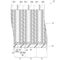
- FIG. 2 is a cross-sectional view showing a schematic diagram of an example of a stacked cell of the zinc secondary battery shown in FIG. 1.
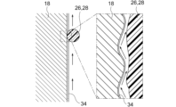
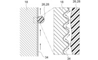
- FIG. 1 is a conceptual diagram for explaining the mechanism of a creep phenomenon. 1 is a cross-sectional view conceptually showing how an electrolyte passes through a minute gap between an electrode terminal having a small surface roughness and an O-ring. 16 is a cross-sectional view conceptually showing a state in which an electrolyte passes through a minute gap between an O-ring and an electrode terminal having a surface roughness greater than that of the electrode terminal shown in FIG. 15.
- FIG. 15 is a perspective view showing a schematic diagram of an example of a stacked cell of the zinc secondary battery shown in FIG. 1.
- FIG. 2 is a cross-sectional view showing a schematic diagram of an example of a stacked cell of the zinc secondary battery shown in FIG
- FIG. 1 is a schematic cross-sectional view showing an example of a conventional zinc secondary battery.
- FIG. 18 is a schematic cross-sectional view showing a state in which the electrode terminal and the upper current collector plate in the conventional zinc secondary battery shown in FIG. 17 are tilted.
- FIG. 19 is a schematic cross-sectional view showing an enlarged view of an electrode terminal and its vicinity in a conventional zinc secondary battery in the state shown in FIG. 18 .
- the zinc secondary battery of the present invention is not particularly limited as long as it is a secondary battery using zinc as the negative electrode and an alkaline electrolyte (typically an aqueous alkali metal hydroxide solution). Therefore, it can be a nickel-zinc secondary battery, a silver oxide zinc secondary battery, a manganese oxide zinc secondary battery, an air zinc secondary battery, or any other type of alkaline zinc secondary battery.
- the positive electrode active material layer contains nickel hydroxide and/or nickel oxyhydroxide, thereby making the zinc secondary battery a nickel-zinc secondary battery.
- the positive electrode active material layer may be an air electrode layer, thereby making the zinc secondary battery an air zinc secondary battery.
- the zinc secondary battery 10 includes a stacked cell 12, a battery case body 14, an upper cover 16, an electrode terminal 18, and a leakage suppression current collecting structure 20.
- the stacked cell 12 has battery components of a zinc secondary battery of an upper tab current collecting type with a tab lead 22 extending from the upper part.
- the battery case body 14 is box-shaped, and the stacked cell 12 is housed therein so that each of the battery components is vertical (i.e., perpendicular to the ground surface).
- the upper cover 16 is a long plate-like member that closes the upper opening of the battery case body 14. As shown in FIGS.
- the leakage suppression current collecting structure 20 is a structure for suppressing leakage from the electrode terminal 18, and includes a stepped hole 24, a first O-ring 26, a second O-ring 28, the electrode terminal 18, an upper current collecting plate 30, a stacked cell 12, and at least one convex portion 32.
- the stepped hole 24 is formed as a through hole with at least three stages including a large diameter hole 24a, a medium diameter hole 24b, and a small diameter hole 24c in this order from the front surface (the outer surface of the battery) to the back surface (the inner surface of the battery) of the top cover 16.
- the first O-ring 26 is disposed in the step formed by the large diameter hole 24a and the medium diameter hole 24b
- the second O-ring 28 is disposed in the step formed by the medium diameter hole 24b and the small diameter hole 24c.
- the electrode terminal 18 includes an external terminal portion 18a protruding from the front surface of the top cover 16, a flange-shaped large diameter portion 18b in surface contact with the front surface of the top cover 16, a medium diameter portion 18c having a diameter that fits the medium diameter hole 24b, and a small diameter portion 18d having a diameter that fits the small diameter hole 24c, and is inserted into the stepped hole 24 and fits liquid-tightly with the stepped hole 24 via a first O-ring 26 and a second O-ring 28.
- the upper current collector 30 is a current collector connected to the lower end of the electrode terminal 18, and includes a current collector body 30a and a bent portion 30b.
- the current collector body 30a is disposed parallel to the top cover 16, while the bent portion 30b bends vertically downward and extends from a position closer to the center of the battery than the electrode terminal 18 of the current collector body 28a.
- the tab lead 22 is joined to the bent portion 30b, and the stacked cell 12 is suspended from the bent portion 30b.
- the convex portion 32 is provided on the back surface of the top cover 16 at a position outside the electrode terminals 18, extending in the short-side direction of the top cover 16, and is in surface contact with the current collector body 30a to provide a fulcrum.
- the longitudinal direction of the top cover 16, which is the direction from the center of the battery toward the outside, is defined as the X-direction
- the short-side direction of the top cover 16 is defined as the Y-direction.
- the leakage suppressing current collecting structure 20 When the leakage suppressing current collecting structure 20 is viewed in cross section in the Y direction, with respect to the central axis A1 of the electrode terminal 18, the central axis A2 in the X direction of the joint portion between the bent portion 30b and the tab lead 22, and the central axis A3 of the convex portion 32 located at the position farthest from the electrode terminal 18 in the X direction, the ratio of the distance b between the central axis A1 and the central axis A3 to the distance a between the central axis A1 and the central axis A2 (i.e., b/a) is 0.85 or more.
- the joint portion between the electrode terminal 18 and the tab lead 22 of the upper current collecting plate 30, and the convex portion 32 that provides a fulcrum on the back surface of the upper cover 16 are arranged to satisfy a predetermined positional relationship, thereby making it possible to effectively delay leakage due to creep from the terminal sealing structure while employing a simple terminal that can be manufactured by heading.
- the creep phenomenon is a phenomenon in which the electrolyte creeps up the surface of the electrode terminal and leaks out of the battery container.
- FIG. 14 conceptually shows the mechanism of the creep phenomenon when a part of the metal member 19 (assuming an electrode terminal or an upper current collector) is immersed in the electrolyte 34 (assuming an aqueous potassium hydroxide solution). As shown in FIG. 14, the creep phenomenon progresses as follows: 1) H 2 O molecules derived from the surrounding environment combine with electrons e ⁇ present in the metal member 19 to generate OH ⁇ , and 2) K + in the electrolyte 34 is attracted to this OH ⁇ .
- Patent Document 2 discloses a terminal structure of a complex shape using two O-rings to suppress leakage, but the manufacturing of such a terminal requires many steps, and therefore the manufacturing cost is high.
- the terminal having a complex shape with a recess as disclosed in Patent Document 2 cannot be manufactured by forging, but the electrode terminal 18 adopted in the present invention has a simple stepped shape having an external terminal portion 18a, a large diameter portion 18b, a medium diameter portion 18c, and a small diameter portion 18d in order as shown in Figures 3 and 7, and therefore has the advantage of being able to be manufactured by forging.
- the part of the electrode terminal 18 that is fitted into the stepped hole 24 has a three-step structure that does not have a recess including the large diameter portion 18b, the medium diameter portion 18c, and the small diameter portion 18d, it can be said that it is particularly suitable for manufacturing by forging.
- the electrode terminal 18 can be manufactured by forging in this way leads to a reduction in manufacturing costs because the number of steps is reduced compared to other manufacturing methods such as cutting and casting.
- the decrease in liquid tightness caused by the weight of the stacked cells as shown in Figures 18 and 19 is also less likely to occur according to the leakage suppression current collecting structure 20 of the present invention.
- the leakage suppression current collecting structure 20 is structured to be difficult to deform due to the weight of the stacked cells 12. That is, as shown in Fig. 4, in the leakage suppression current collecting structure 20, a force acts downward (in the direction of arrow A) on the bent portion 30b due to the weight of the stacked cells 12.
- a moment is generated in the direction of arrow B centered on the electrode terminal 18.
- a downward force acts so that the portion of the current collecting plate body 30a close to the bent portion 30b sinks
- an upward force acts so that the portion of the electrode terminal 18 far from the bent portion 30b floats.
- point E which is far from the bent portion 30b among the contact points between the upper cover 16 and the current collecting plate body 30a, functions as a fulcrum
- point F which is close to the bent portion 30b among the contact points between the electrode terminal 18 and the stepped hole 24, functions as a fulcrum.
- a force acts in a direction that increases the gap between the electrode terminal 18 and the stepped hole 24.
- the convex portion 32 is provided on the back surface of the top cover 16 at a position outside the electrode terminal 18, extending in the short direction of the top cover 16, and is in surface contact with the current collecting plate body 30a to provide a fulcrum.
- the relative positional relationship of the electrode terminal 18, the bent portion 30b, the tab lead 22, and the convex portion 32 (located at the position farthest from the electrode terminal 18 in the X direction) is set so that the ratio (b/ a , see Figures 7 and 11) of the distance b between the central axis A1 and the central axis A3 to the distance a between the central axis A1 and the central axis A2 is 0.85 or more, thereby minimizing the above-mentioned moment (see arrow B).
- the convex portion 32 can function as a fulcrum for effectively absorbing the force applied to the current collector plate body 30a. That is, by increasing the distance H shown in FIG. 6, the force applied to the fulcrum can be absorbed by the entire upper cover 16 including the convex portion 32, so that the above-mentioned moment can be minimized. Therefore, by reducing the forces shown by the arrows C and D in FIG.
- the gap between the electrode terminal 18 and the stepped hole 24 is prevented from increasing in the lateral direction (in the direction of the arrow G), thereby preventing a decrease in liquid-tightness.
- leakage due to creep from the terminal sealing structure can be effectively delayed.
- the ratio of the distance b between the central axis A 1 and the central axis A 3 to the distance a between the central axis A 1 and the central axis A 2 is 0.85 or more, preferably 0.90 to 1.50, more preferably 1.00 to 1.50, and even more preferably 1.10 to 1.50.
- the distance a between the central axis A 1 and the central axis A 2 is preferably 10 to 40 mm, more preferably 10 to 30 mm, and even more preferably 10 to 20 mm.
- the distance b between the central axis A 1 and the central axis A 3 is preferably 10 to 40 mm, more preferably 15 to 35 mm, and even more preferably 20 to 30 mm. Within these ranges, leakage due to creep from the terminal sealing structure can be more effectively delayed.
- the zinc secondary battery 10 comprises a stacked cell 12, a battery case body 14, a top cover 16, electrode terminals 18, and a leakage suppression current collecting structure 20.
- the stacked cell 12 has the battery components of a zinc secondary battery with an upper tab current collection system in which a tab lead 22 extends from the top.
- a stacked cell 12 can be one in which positive and negative electrode plates are stacked with a separator and/or a liquid-retaining member interposed therebetween. A preferred embodiment of the stacked cell 12 will be described later.
- the battery case body 14 is a box-shaped case with an upper opening, in which the stacked cells 12 are housed so that each of the battery components is vertical (i.e., perpendicular to the ground surface).
- the top cover 16 is a long plate-shaped member that closes the upper opening of the battery case body 14. That is, the battery case 13 can be configured as an airtight container by closing the upper opening of the battery case body 14 with the top cover 16.
- the top cover 16 may have a pressure release valve for releasing gas.
- the top cover 16 shown in Figures 8, 10, and 11 has a pressure release valve hole 17 so that a pressure release valve can be disposed therein. Both the battery case body 14 and the top cover 16 are preferably made of resin.
- the resin that constitutes the battery case body 14 and the top cover 16 is preferably a resin that is resistant to alkali metal hydroxides such as potassium hydroxide, more preferably a polyolefin resin, ABS resin, or modified polyphenylene ether, and even more preferably an ABS resin or modified polyphenylene ether.
- the preferred inner dimensions of the battery case body 14 are 150-200 mm in length, 10-50 mm in width, and 100-200 mm in height, and more preferably 180-200 mm in length, 10-40 mm in width, and 120-180 mm in height.
- the preferred outer dimensions of the battery case body 14 are 150-250 mm in length, 10-60 mm in width, and 100-250 mm in height, and more preferably 180-220 mm in length, 20-40 mm in width, and 130-200 mm in height.
- the preferred size of the top cover 16 is 150-250 mm in length, 10-60 mm in width, and more preferably 180-220 mm in length, and 20-40 mm in width.
- the top cover 16 has a stepped hole 24 and at least one convex portion 32 provided on the back surface of the top cover 16 as components forming part of the leakage suppression current collecting structure 20.
- the stepped hole 24 is formed as a through hole with at least three stages, including a large diameter hole 24a, a medium diameter hole 24b, and a small diameter hole 24c, in that order from the front surface of the top cover 16 (the outer surface of the battery) to the back surface (the inner surface of the battery).
- the inner diameter of the large diameter hole 24a is preferably 10 to 30 mm, more preferably 10 to 20 mm.
- the inner diameter of the medium diameter hole 24b is preferably 5 to 15 mm, more preferably 5 to 10 mm.
- the inner diameter of the small diameter hole 24c is preferably 2 to 15 mm, more preferably 2 to 10 mm.
- the preferred number of stages of the stepped hole 24 is three.
- the convex portion 32 is provided on the back surface of the top cover 16 at a position outside the electrode terminal 18, extending in the short direction of the top cover 16, and is in surface contact with the current collector body 30a to provide a fulcrum.
- the thickness of the convex portion 32 is preferably 2 to 15 mm, and more preferably 2 to 10 mm. With such a thickness, the convex portion 32 can ensure sufficient strength to withstand the force applied to the fulcrum from the current collector body 30a due to the weight of the stacked cells 12.
- the electrode terminal 18 penetrates the top cover 16 and protrudes to the outside. As shown in Figures 3 and 7, the electrode terminal 18 is a component that forms part of the leakage suppression current collecting structure 20 and includes an external terminal portion 18a protruding from the front surface of the top cover 16, a flange-shaped large diameter portion 18b that is in surface contact with the front surface of the top cover 16, a medium diameter portion 18c having a diameter that fits the medium diameter hole 24b, and a small diameter portion 18d having a diameter that fits the small diameter hole 24c.
- the electrode terminal 18 is inserted into the stepped hole 24 and only needs to have a shape and size that allows it to be liquid-tightly fitted into the stepped hole 24 via the first O-ring 26 and the second O-ring 28.
- the electrode terminal 18 When the electrode terminal 18 is inserted into the stepped hole 24, the first O-ring 26 and the second O-ring 28 are compressed between the electrode terminal 18 and the stepped hole 24, closing the gap. At the same time, the flange-shaped large diameter portion 18b comes into surface contact (preferably without any gap) with the front surface of the top cover 16. In this way, the liquid-tightness of the leakage suppression current collecting structure 20 is ensured.
- the electrode terminal 18 is preferably configured so that the outer peripheries of the large diameter portion 18b, the medium diameter portion 18c, and the small diameter portion 18d are concentric.
- the diameter of the external terminal portion 18a is preferably 3 to 10 mm, more preferably 3 to 7 mm.
- the diameter of the large diameter portion 18b is preferably 10 to 30 mm, more preferably 10 to 20 mm.
- the diameter of the medium diameter portion 18c is preferably 5 to 15 mm, more preferably 5 to 10 mm.
- the diameter of the small diameter portion 18d is preferably 2 to 15 mm, more preferably 2 to 10 mm.
- the electrode terminal 18 may be made of any metal material commonly used as a terminal, and is not particularly limited, but may be made of SWCH (cold heading carbon steel), for example.
- the electrode terminal 18 is preferably a pressed product having a three-stage structure consisting of a large diameter portion 18b, a medium diameter portion 18c, and a small diameter portion 18d.
- a three-stage structure without a recess including the large diameter portion 18b, the medium diameter portion 18c, and the small diameter portion 18d, is particularly suitable for pressing. This is because a stepped structure with four or more stages is difficult to produce by pressing.
- the three-stage structure without a recess means the basic structure of the electrode terminal 18, and the "recess" does not mean a fine groove or recess such as a screw groove that may be added in an optional additional process.
- the electrode terminal 18 (specifically the external terminal portion 18a) shown in Figures 3 and 8 to 11 has a screw groove formed by rolling after the basic structure is added by pressing.
- the arithmetic mean roughness Ra of the surface of the portion of the electrode terminal 18 (particularly the negative terminal 18n) facing the first O-ring 26, the second O-ring 28, and the stepped hole 24 is preferably 0.2 to 1.0 ⁇ m, more preferably 0.4 to 1.0 ⁇ m, and even more preferably 0.6 to 1.0 ⁇ m. This makes it possible to further delay leakage due to creep from the terminal sealing structure. That is, as shown in FIG. 15, because there are minute irregularities on the surface of the electrode terminal 18, a minute gap inevitably occurs between the electrode terminal 18 and the O-ring 26 or 28, and the electrolyte can pass through this minute gap.
- the surface roughness of the electrode terminal 18 (particularly the negative terminal 18n) facing the O-rings 26 and 28 is adjusted (roughened) to satisfy the above-mentioned Ra range, and the distance that the electrolyte 34 creeps up the surface of the electrode terminal 18 is extended as shown in FIG. 16, so that leakage due to creeping can be delayed.
- the method for adjusting the surface roughness of the electrode terminal 18, and the surface roughness can be appropriately changed by changing the manufacturing method of the electrode terminal 18.
- the surface roughness may be increased by subjecting the manufactured electrode terminal 18 to a roughening treatment such as blasting.
- the surface roughness, i.e., the arithmetic mean roughness Ra can be measured using a measuring device such as a laser microscope or a stylus-type surface roughness measuring device in accordance with JIS B0601 (2001).
- the first O-ring 26 and the second O-ring 28 are sealing members for ensuring liquid-tightness between the electrode terminal 18 and the stepped hole 24.
- the first O-ring 26 is disposed in the step formed by the large diameter hole 24a and the medium diameter hole 24b (i.e., the bottom of the large diameter hole 24a excluding the medium diameter hole 24b), while the second O-ring 28 is disposed in the step formed by the medium diameter hole 24b and the small diameter hole 24c (i.e., the bottom of the medium diameter hole 24b excluding the small diameter hole 24c).
- the diameter of the first O-ring 26 is preferably 5 to 15 mm, more preferably 8 to 12 mm.
- the diameter of the second O-ring 28 is preferably 2 to 13 mm, more preferably 5 to 10 mm.
- the material of the first O-ring 26 and the second O-ring 28 is not particularly limited, but is preferably made of EPDM (ethylene propylene diene rubber).
- the convex portion 32 is provided at a position on the back surface of the top cover 16 outside the electrode terminal 18, extending in the short direction of the top cover 16, and is in surface contact with the current collector body 30a to provide a fulcrum.
- the thickness of the current collector body 30a is preferably 1 to 5 mm, more preferably 2 to 4 mm.
- the thickness of the bent portion 30b is preferably 1 to 5 mm, more preferably 2 to 4 mm.
- the material of the upper current collector 30 is not particularly limited as long as it is a conductive material such as metal, but is preferably made of SPCC (cold rolled steel plate).
- the Stacked Cell Figures 12 and 13 show a preferred embodiment of a stacked cell 12.
- the stacked cell 12 includes a plurality of positive electrode plates 36, a plurality of positive electrode tab leads 22p extending from each end of the positive electrode plates 36, a plurality of negative electrode plates 38, a plurality of negative electrode tab leads 22n extending from each end of the negative electrode plates 38 at positions not overlapping with the positive electrode tab leads 22p, a plurality of hydroxide ion conductive separators 40, and an electrolyte 34, and the positive electrode plates 36 and the negative electrode plates 38 are stacked alternately with the hydroxide ion conductive separator 40 sandwiched therebetween.
- the zinc secondary battery 10 preferably includes a plurality of unit cells 11 each having a pair of positive electrode plates 36 and negative electrode plates 38 together with the hydroxide ion conductive separator 40, and the plurality of unit cells 11 form a multi-layer cell as a whole.
- This is a so-called assembled battery or stacked battery configuration, and is advantageous in that a high voltage and a large current can be obtained.
- a preferred zinc secondary battery 10 has two leakage-suppressing current collecting structures 20 positioned on opposite sides, as shown in Figures 1 and 8 to 10, and a collection of multiple positive electrode tab leads 22p is joined to the bent portion 30b of one leakage-suppressing current collecting structure 20, and a collection of multiple negative electrode tab leads 22n is joined to the bent portion 30b of the other leakage-suppressing current collecting structure 20.
- the positive electrode plate 36 includes a positive electrode active material layer 36a.
- the positive electrode active material constituting the positive electrode active material layer 36a may be appropriately selected from known positive electrode materials according to the type of zinc secondary battery, and is not particularly limited.
- a positive electrode containing nickel hydroxide and/or nickel oxyhydroxide may be used.
- an air electrode may be used as the positive electrode.
- the positive electrode plate 36 further includes a positive electrode collector (not shown), and it is preferable that a metallic positive electrode tab lead 22p is further provided on the positive electrode collector so as to extend upward from the positive electrode collector.
- a preferable example of the positive electrode collector is a nickel porous substrate such as a foamed nickel plate.
- a paste containing an electrode active material such as nickel hydroxide is uniformly applied to a nickel porous substrate and dried to preferably produce a positive electrode plate consisting of a positive electrode/positive electrode collector.
- the positive electrode plate 36 shown in FIG. 13 includes a positive electrode current collector (e.g., foamed nickel), but is not shown.
- the positive electrode tab lead 22p may be made of the same material as the positive electrode current collector, or may be made of a different material.
- the positive electrode current collector is a nickel porous substrate such as a foamed nickel plate, it can be processed into a tab shape by pressing it.
- the positive electrode tab lead 22p may be extended by adding another tab lead to such a tab.
- the positive electrode tab lead 22p and the bent portion 30b can be joined using a known joining method such as ultrasonic welding (ultrasonic bonding), laser welding, TIG welding, or resistance welding.
- the positive electrode plate 36 may contain at least one additive selected from the group consisting of silver compounds, manganese compounds, and titanium compounds, which can promote the positive electrode reaction that absorbs hydrogen gas generated by the self-discharge reaction.
- the positive electrode plate 36 may further contain cobalt. Cobalt is preferably contained in the positive electrode plate 36 in the form of cobalt oxyhydroxide. In the positive electrode plate 36, cobalt functions as a conductive additive, thereby contributing to improving the charge/discharge capacity.
- the negative electrode plate 38 includes a negative electrode active material layer 38a.
- the negative electrode active material constituting the negative electrode active material layer 38a includes at least one selected from the group consisting of zinc, zinc oxide, zinc alloys, and zinc compounds. Zinc may be included in any form of zinc metal, zinc compound, or zinc alloy, so long as it has electrochemical activity suitable for a negative electrode. Preferred examples of negative electrode materials include zinc oxide, zinc metal, calcium zincate, etc., and a mixture of zinc metal and zinc oxide is more preferred.
- the negative electrode active material may be configured in a gel form, or may be mixed with the electrolyte 34 to form a negative electrode mixture. For example, a gelled negative electrode can be easily obtained by adding an electrolyte and a thickener to the negative electrode active material. Examples of thickeners include polyvinyl alcohol, polyacrylate, CMC, alginic acid, etc., and polyacrylic acid is preferred because of its excellent chemical resistance to strong alkalis.
- a mercury- and lead-free zinc alloy known as a mercury-free zinc alloy can be used.
- a zinc alloy containing 0.01 to 0.1 mass% indium, 0.005 to 0.02 mass% bismuth, and 0.0035 to 0.015 mass% aluminum is preferable because it has the effect of suppressing hydrogen gas generation.
- indium and bismuth are advantageous in terms of improving discharge performance.
- the use of a zinc alloy for the negative electrode can improve safety by suppressing hydrogen gas generation by slowing down the self-dissolution rate in alkaline electrolyte.
- the shape of the negative electrode material is not particularly limited, but it is preferably in powder form, which increases the surface area and allows it to handle large current discharges.
- the average particle size of the negative electrode material is preferably in the range of 3 to 100 ⁇ m in short axis for zinc alloys; within this range, the large surface area makes it suitable for handling large current discharges, and it is easy to mix uniformly with the electrolyte and gelling agent, making it easy to handle when assembling the battery.
- the negative electrode plate 38 further includes a negative electrode collector 38b.
- the negative electrode collector 38b is provided inside and/or on the surface of the negative electrode active material layer 38a. That is, the negative electrode active material layer 38a may be arranged on both sides of the negative electrode collector 38b, or the negative electrode active material layer 38a may be arranged on only one side of the negative electrode collector 38b. It is preferable that the negative electrode collector 38b is further provided with a negative electrode tab lead 22n extending upward therefrom.
- the negative electrode tab lead 22n may be made of the same material as the negative electrode collector 38b, or may be made of a different material.
- the negative electrode tab lead 22n may be extended by adding another tab lead to such a tab.
- a plurality of negative electrode tab leads 22n are joined to the bent portion 30b of the upper current collector 30 (to which the positive electrode tab lead 22p is not joined).
- the negative electrode tab lead 22n and the bent portion 30b can be joined using a known joining method such as ultrasonic welding (ultrasonic bonding), laser welding, TIG welding, or resistance welding.
- a metal plate having a plurality (or a large number) of openings as the negative electrode current collector 38b.
- Preferred examples of such a negative electrode current collector 38b include expanded metal, punched metal, and metal mesh, and combinations thereof, more preferably copper expanded metal, copper punched metal, and combinations thereof, and particularly preferably copper expanded metal.
- a mixture containing zinc oxide powder and/or zinc powder, and optionally a binder e.g. polytetrafluoroethylene particles
- a binder e.g. polytetrafluoroethylene particles
- the expanded metal is a mesh-shaped metal plate in which a metal plate is expanded while making staggered cuts using an expander, and the cuts are formed into a diamond or tortoiseshell shape.
- Punched metal also known as perforated metal, is a metal plate with holes punched into it.
- Metal mesh is a metal product with a wire mesh structure, and is different from expanded metal and punched metal.
- the hydroxide ion conductive separator 40 is provided so as to isolate the positive electrode plate 36 and the negative electrode plate 38 in a manner that allows hydroxide ion conductivity.
- the positive electrode plate 36 and/or the negative electrode plate 38 may be configured to be covered or wrapped with the hydroxide ion conductive separator 40.
- This makes it possible to manufacture a zinc secondary battery (particularly a stacked battery thereof) capable of preventing zinc dendrite extension extremely easily and with high productivity, eliminating the need for a complicated sealing joint between the hydroxide ion conductive separator 40 and the battery container.
- a simple configuration in which the hydroxide ion conductive separator 40 is disposed on one side of the positive electrode plate 36 or the negative electrode plate 38 may also be used.
- the hydroxide ion conductive separator 40 is not particularly limited as long as it is a separator capable of isolating the positive electrode plate 36 and the negative electrode plate 38 in a manner that allows hydroxide ion conductivity, but is typically a separator that includes a hydroxide ion conductive solid electrolyte and selectively passes hydroxide ions solely by utilizing hydroxide ion conductivity.
- a preferred hydroxide ion conductive solid electrolyte is a layered double hydroxide (LDH) and/or an LDH-like compound.
- the hydroxide ion conductive separator 40 is preferably an LDH separator.
- an "LDH separator” is defined as a separator that includes an LDH and/or an LDH-like compound and selectively passes hydroxide ions solely by utilizing the hydroxide ion conductivity of the LDH and/or the LDH-like compound.
- an "LDH-like compound” is a hydroxide and/or oxide of a layered crystal structure that may not be called an LDH but has hydroxide ion conductivity, and can be considered an equivalent of an LDH.
- LDH can be interpreted as including not only LDH but also LDH-like compounds.
- the LDH separator is preferably composited with a porous substrate.
- the LDH separator preferably further comprises a porous substrate, and is composited with the porous substrate in a form in which the pores of the porous substrate are filled with LDH and/or LDH-like compounds. That is, in a preferred LDH separator, the pores of the porous substrate are blocked with LDH and/or LDH-like compounds so as to exhibit hydroxide ion conductivity and gas impermeability (and therefore function as an LDH separator exhibiting hydroxide ion conductivity).
- the porous substrate is preferably made of a polymeric material, and it is particularly preferred that the LDH and/or LDH-like compounds are incorporated throughout the entire thickness of the porous substrate made of a polymeric material.
- LDH separators such as those disclosed in Patent Documents 3 to 9 can be used.
- the thickness of the LDH separator is preferably 5 to 100 ⁇ m, more preferably 5 to 80 ⁇ m, even more preferably 5 to 60 ⁇ m, and particularly preferably 5 to 40 ⁇ m.
- the zinc secondary battery 10 may further include a liquid-retaining member 42 in contact with the positive electrode plate 36 and/or the negative electrode plate 38.
- a liquid-retaining member 42 in contact with the positive electrode plate 36 and/or the negative electrode plate 38.
- the positive electrode plate 36 and/or the negative electrode plate 38 is covered or wrapped with the liquid-retaining member 42.
- a simple configuration in which the liquid-retaining member 42 is disposed on one side of the positive electrode plate 36 or the negative electrode plate 38 may also be used.
- the electrolyte 34 can be evenly present between the positive electrode plate 36 and/or the negative electrode plate 38 and the hydroxide ion conductive separator 40, and hydroxide ions can be efficiently exchanged between the positive electrode plate 36 and/or the negative electrode plate 38 and the hydroxide ion conductive separator 40.
- the liquid-retaining member 42 is not particularly limited as long as it is a member capable of retaining the electrolyte 34, but is preferably a sheet-like member.
- liquid-retaining member 42 examples include nonwoven fabric, water-absorbent resin, liquid-retaining resin, porous sheet, and various spacers, but nonwoven fabric is particularly preferred because it allows the production of a negative electrode structure with good performance at low cost.
- the liquid-retaining member 42 or nonwoven fabric preferably has a thickness of 10 to 200 ⁇ m, more preferably 20 to 200 ⁇ m, even more preferably 20 to 150 ⁇ m, particularly preferably 20 to 100 ⁇ m, and most preferably 20 to 60 ⁇ m. If the thickness is within the above range, a sufficient amount of electrolyte 34 can be retained in the liquid-retaining member 42 while keeping the overall size of the positive electrode structure and/or negative electrode structure compact and without waste.
- the outer edges of the plates are closed (except for the upper edges from which the positive electrode tab lead 22p and the negative electrode tab lead 22n extend).
- the closed edge of the outer edge of the liquid-retaining member 42 and/or the hydroxide ion conductive separator 40 is realized by folding the liquid-retaining member 42 and/or the hydroxide ion conductive separator 40, or by sealing the liquid-retaining members 42 together and/or the hydroxide ion conductive separators 40 together.
- sealing methods include adhesives, heat welding, ultrasonic welding, adhesive tape, sealing tape, and combinations thereof.
- the LDH separator including the porous substrate made of a polymer material has the advantage of being flexible and therefore easy to bend, it is preferable to form the LDH separator into a long shape and fold it to form a state in which one side of the outer edge is closed.
- Thermal welding and ultrasonic welding may be performed using a commercially available heat sealer, etc., but in the case of sealing between LDH separators, it is preferable to perform thermal welding and ultrasonic welding by sandwiching the outer peripheral portion of the liquid-retaining member 42 between the LDH separators that constitute the outer peripheral portion, since this allows for more effective sealing.
- the adhesive, adhesive tape, and sealing tape may be commercially available products, but it is preferable to use those that contain a resin that is resistant to alkali in order to prevent deterioration in an alkaline electrolyte.
- examples of preferred adhesives include epoxy resin adhesives, natural resin adhesives, modified olefin resin adhesives, and modified silicone resin adhesives, and among them, epoxy resin adhesives are more preferred because they are particularly excellent in alkali resistance.
- An example of a product of an epoxy resin adhesive is the epoxy adhesive Hysol (registered trademark) (manufactured by Henkel).
- the outer edge of one side that is the upper end of the hydroxide ion conductive separator 40 is open.
- This open-top configuration makes it possible to deal with problems that occur when a nickel-zinc battery or the like is overcharged. That is, when a nickel-zinc battery or the like is overcharged, oxygen (O 2 ) may be generated at the positive electrode plate 36, but the LDH separator has such a high density that it allows only hydroxide ions to pass through, and therefore does not allow O 2 to pass through.
- the open-top stacked cell 12 can be used in a sealed zinc secondary battery to improve overcharge resistance.
- the vent hole may be opened after sealing the outer edge of one side serving as the upper end of the LDH separator, or a part of the outer edge may be left unsealed so that a vent hole is formed during sealing.
- the electrolyte 34 preferably contains an aqueous solution of an alkali metal hydroxide.
- alkali metal hydroxides include potassium hydroxide, sodium hydroxide, lithium hydroxide, and ammonium hydroxide, with potassium hydroxide being more preferred.
- a zinc compound such as zinc oxide or zinc hydroxide may be added to the electrolyte.
- the electrolyte may be mixed with a positive electrode active material and/or a negative electrode active material to be present in the form of a positive electrode composite and/or a negative electrode composite.
- the electrolyte may also be gelled to prevent leakage of the electrolyte.
- the gelling agent it is preferable to use a polymer that absorbs the solvent of the electrolyte and swells, and starch or a polymer such as polyethylene oxide, polyvinyl alcohol, or polyacrylamide is used.
- Examples A1 to A6 (1) Preparation of Nickel-Zinc Secondary Battery A positive electrode plate, a positive electrode current collector, a negative electrode plate, a negative electrode current collector, an LDH separator, a nonwoven fabric, a battery container, and an electrolyte solution shown below were prepared.
- Positive electrode plate The pores of the nickel foam are filled with a positive electrode paste containing nickel hydroxide and a binder and then dried (there is an uncoated area near one end of the nickel foam where the positive electrode paste is not applied).
- Positive electrode current collecting member The uncoated portion of the foamed nickel that constitutes the positive electrode plate is compressed by a roll press to form a tab, and a tab lead (made of pure nickel, thickness: 100 ⁇ m) is ultrasonically welded to this tab to extend it.
- Negative electrode plate A negative electrode paste containing ZnO powder, metallic Zn powder, polytetrafluoroethylene (PTFE) and propylene glycol is pressed onto a current collector (copper expanded metal) (there is an uncoated area near one end of the copper expanded metal where the negative electrode paste is not applied).
- Negative electrode current collecting member A tab lead (made of copper, thickness: 100 ⁇ m) was connected to the uncoated portion of the copper expanded metal by ultrasonic welding.
- LDH separator Ni-Al-Ti-LDH (layered double hydroxide) is precipitated in the pores and on the surface of a polyethylene microporous membrane by hydrothermal synthesis and roll-pressed; thickness: 20 ⁇ m
- Non-woven fabric Polypropylene, thickness 100 ⁇ m
- Battery case body box-shaped case made of modified polyphenylene ether resin (equipped with a pressure relief valve that allows gas generated inside the case to be released), internal dimensions: length 190 mm, width 24 mm, height 165 mm, external dimensions: length 200 mm, width 30 mm, height 170 mm (not including the height of the positive and negative terminals)
- Top cover a top cover made of modified polyphenylene ether resin having stepped holes (three through holes consisting of a large diameter hole (inner diameter: 11.3 mm), a medium diameter hole (inner diameter: 6.2 mm), and a small diameter hole (inner diameter: 4.2 mm)) as shown in Figures 8 to 11 and a convex portion
- Positive electrode terminal and negative electrode terminal SWCH terminal (made by pressing) having an external terminal portion (diameter: 5 mm), a large diameter portion (diameter: 15 mm), a medium diameter portion (diameter: 6 mm), and a small diameter portion (diameter: 4 mm) in the shapes shown in FIGS.
- First O-ring EPDM O-ring (diameter: 11.5 mm)
- Second O-ring EPDM O-ring (diameter: 6.5 mm)
- Positive electrode upper current collector plate and negative electrode upper current collector plate SPCC plate-shaped member having a current collector plate body (thickness: 3 mm) and a bent portion (thickness: 3 mm) in the shapes shown in Figures 8 to 11
- the positive electrode plate was wrapped in nonwoven fabric so that it covered both sides, with the nonwoven fabric slightly protruding from the remaining three sides except for the side from which the positive electrode current collector extends.
- the excess nonwoven fabric protruding from the three sides of the positive electrode plate was heat-sealed with a heat seal bar to obtain a positive electrode structure.
- the negative electrode plate was wrapped in nonwoven fabric and LDH separator in that order from both sides, with the nonwoven fabric and LDH separator slightly protruding from the remaining three sides except for the side from which the negative electrode current collector extends.
- the excess nonwoven fabric and LDH separator protruding from the three sides of the negative electrode plate were heat-sealed with a heat seal bar to obtain a negative electrode structure. In this way, multiple positive electrode structures and multiple negative electrode structures were prepared.
- An electrode laminate was produced by alternately stacking 12 positive electrode structures and 13 negative electrode structures.
- the positive electrode tab leads 22p and the negative electrode tab leads 22n are designed to extend from different positions from each other when viewed in a plan view from the electrode laminate, so that the positive electrode tab leads 22p are overlapped with each other, while the negative electrode tab leads 22n are overlapped with each other at a different position.
- the overlapping portions of the positive electrode tab leads 22p were joined together to the bent portion 30b of the positive electrode upper current collector 30p by laser welding.
- the overlapping portions of the negative electrode tab leads 22n were joined together to the bent portion 30b of the negative electrode upper current collector 30n by laser welding.
- a stack of electrode structures including the positive electrode tab leads 22p and the negative electrode tab leads 22n was obtained as the laminated cell 12.
- the stacked cell 12 joined to the positive electrode upper current collector plate 30p and the negative electrode upper current collector plate 30n was placed in a box-shaped battery case body 14, the electrolyte 34 was injected to impregnate the stacked cell 12, and the top lid 16 was closed and sealed. In this way, a nickel-zinc secondary battery 10 was produced.
- Examples B1 to B4 (for reference) A conventional modified polyphenylene ether resin top cover (b/a is less than 0.85) as shown in Figures 17 to 19 and a nickel-plated SWCH having a surface with an arithmetic average roughness Ra shown in Table 2
- the accelerated leakage resistance test was carried out in the same manner as in Examples A1 to A6, except that a negative electrode terminal made of the same material was used.
- Four types of negative electrode terminals were fabricated, each with a different arithmetic mean roughness Ra of the surface of the portion to be bonded to the negative electrode. The change in Ra was achieved by appropriately changing the manufacturing method of the negative electrode terminal as shown in Table 2.
- the nickel-zinc secondary battery thus prepared was stored in a high-temperature and high-humidity environment (65° C./80%). The number of days from the start of storage until the carbonate derived from the electrolyte precipitated on the top of the negative electrode terminal 18n was first visually observed was measured. The results are shown in Table 2.
- the number of days until leakage is confirmed can be extended by increasing the arithmetic mean roughness Ra of the surfaces of the negative electrode terminal facing the first O-ring, the second O-ring, and the stepped hole.
- these Examples B1 to B4 are positioned as reference examples in that they are not examples using a top cover that satisfies the requirement of the present invention of a b/a ratio of 0.85 or more.
- the finding that leakage can be more effectively suppressed by increasing the arithmetic mean roughness Ra can be said to naturally apply to the zinc secondary battery of the present invention (b/a ratio of 0.85 or more) with an improved top cover structure.
- increasing the arithmetic mean roughness Ra of the above-mentioned specific parts of the negative electrode terminal can be said to be effective in further enhancing the leakage suppression effect in the zinc secondary battery of the present invention.
Landscapes
- Chemical & Material Sciences (AREA)
- Chemical Kinetics & Catalysis (AREA)
- Electrochemistry (AREA)
- General Chemical & Material Sciences (AREA)
- Engineering & Computer Science (AREA)
- Manufacturing & Machinery (AREA)
- Inorganic Chemistry (AREA)
- Composite Materials (AREA)
- Materials Engineering (AREA)
- Ceramic Engineering (AREA)
- Sealing Battery Cases Or Jackets (AREA)
- Connection Of Batteries Or Terminals (AREA)
Priority Applications (1)
| Application Number | Priority Date | Filing Date | Title |
|---|---|---|---|
| JP2025506471A JP7810860B2 (ja) | 2023-03-16 | 2023-11-09 | 亜鉛二次電池 |
Applications Claiming Priority (2)
| Application Number | Priority Date | Filing Date | Title |
|---|---|---|---|
| JP2023-041974 | 2023-03-16 | ||
| JP2023041974 | 2023-03-16 |
Publications (1)
| Publication Number | Publication Date |
|---|---|
| WO2024189972A1 true WO2024189972A1 (ja) | 2024-09-19 |
Family
ID=92754472
Family Applications (1)
| Application Number | Title | Priority Date | Filing Date |
|---|---|---|---|
| PCT/JP2023/040403 Ceased WO2024189972A1 (ja) | 2023-03-16 | 2023-11-09 | 亜鉛二次電池 |
Country Status (2)
| Country | Link |
|---|---|
| JP (1) | JP7810860B2 (https=) |
| WO (1) | WO2024189972A1 (https=) |
Cited By (1)
| Publication number | Priority date | Publication date | Assignee | Title |
|---|---|---|---|---|
| US20250233288A1 (en) * | 2024-01-11 | 2025-07-17 | Yantai Lihua Electric Power Technology Co., Ltd. | Method for assembling pole terminal of cylindrical battery |
Citations (4)
| Publication number | Priority date | Publication date | Assignee | Title |
|---|---|---|---|---|
| JP2015018757A (ja) * | 2013-07-12 | 2015-01-29 | 株式会社豊田自動織機 | 蓄電装置 |
| WO2021193436A1 (ja) * | 2020-03-23 | 2021-09-30 | 日本碍子株式会社 | 亜鉛二次電池及びモジュール電池 |
| JP2021157893A (ja) * | 2020-03-25 | 2021-10-07 | 日本碍子株式会社 | ニッケル亜鉛二次電池 |
| JP2022138491A (ja) * | 2021-03-10 | 2022-09-26 | プライムプラネットエナジー&ソリューションズ株式会社 | 二次電池およびその製造方法 |
-
2023
- 2023-11-09 JP JP2025506471A patent/JP7810860B2/ja active Active
- 2023-11-09 WO PCT/JP2023/040403 patent/WO2024189972A1/ja not_active Ceased
Patent Citations (4)
| Publication number | Priority date | Publication date | Assignee | Title |
|---|---|---|---|---|
| JP2015018757A (ja) * | 2013-07-12 | 2015-01-29 | 株式会社豊田自動織機 | 蓄電装置 |
| WO2021193436A1 (ja) * | 2020-03-23 | 2021-09-30 | 日本碍子株式会社 | 亜鉛二次電池及びモジュール電池 |
| JP2021157893A (ja) * | 2020-03-25 | 2021-10-07 | 日本碍子株式会社 | ニッケル亜鉛二次電池 |
| JP2022138491A (ja) * | 2021-03-10 | 2022-09-26 | プライムプラネットエナジー&ソリューションズ株式会社 | 二次電池およびその製造方法 |
Cited By (2)
| Publication number | Priority date | Publication date | Assignee | Title |
|---|---|---|---|---|
| US20250233288A1 (en) * | 2024-01-11 | 2025-07-17 | Yantai Lihua Electric Power Technology Co., Ltd. | Method for assembling pole terminal of cylindrical battery |
| US12463306B2 (en) * | 2024-01-11 | 2025-11-04 | Yantai Lihua Electric Power Technology Co., Ltd. | Method for assembling pole terminal of cylindrical battery |
Also Published As
| Publication number | Publication date |
|---|---|
| JPWO2024189972A1 (https=) | 2024-09-19 |
| JP7810860B2 (ja) | 2026-02-03 |
Similar Documents
| Publication | Publication Date | Title |
|---|---|---|
| CN101176222A (zh) | 薄片碱性电池 | |
| JP7227381B2 (ja) | アルカリ二次電池及びアルカリ二次電池モジュール | |
| WO2020115955A1 (ja) | 二次電池用正極構造体 | |
| JP7315676B2 (ja) | 電池モジュール | |
| WO2024020299A2 (en) | Cell assembly and all solid-state battery comprising the same | |
| JP7364445B2 (ja) | アルカリ二次電池 | |
| JPWO2020115954A1 (ja) | 二次電池用正極構造体 | |
| JP7810860B2 (ja) | 亜鉛二次電池 | |
| JP7606593B2 (ja) | 亜鉛二次電池 | |
| US20250015339A1 (en) | Zinc secondary battery | |
| CN119278519A (zh) | 锌电池用负极和锌电池 | |
| US20240413486A1 (en) | Zinc secondary battery | |
| JP7506822B2 (ja) | ニッケル亜鉛二次電池 | |
| WO2023162333A1 (ja) | 二次電池及び二次電池モジュール | |
| US20250372725A1 (en) | Zinc secondary battery | |
| JP2023124426A (ja) | 二次電池の製造方法 | |
| US20240014449A1 (en) | Zinc secondary battery | |
| JP7545569B2 (ja) | 亜鉛二次電池 | |
| JP7626646B2 (ja) | 定置型ニッケル亜鉛二次電池 | |
| JP2003077524A (ja) | 密閉角形電池 | |
| JP7724286B2 (ja) | ニッケル亜鉛二次電池 | |
| JP2025140837A (ja) | アルカリ二次電池 | |
| WO2025187124A1 (ja) | 電池モジュール | |
| WO2024029364A1 (ja) | 負極板及びそれを備えた亜鉛二次電池 | |
| WO2025187123A1 (ja) | 亜鉛二次電池 |
Legal Events
| Date | Code | Title | Description |
|---|---|---|---|
| 121 | Ep: the epo has been informed by wipo that ep was designated in this application |
Ref document number: 23927583 Country of ref document: EP Kind code of ref document: A1 |
|
| WWE | Wipo information: entry into national phase |
Ref document number: 2025506471 Country of ref document: JP |
|
| NENP | Non-entry into the national phase |
Ref country code: DE |
|
| 122 | Ep: pct application non-entry in european phase |
Ref document number: 23927583 Country of ref document: EP Kind code of ref document: A1 |