WO2024189720A1 - シリーズハイブリッド車両のバッテリ制御方法およびシリーズハイブリッド車両 - Google Patents
シリーズハイブリッド車両のバッテリ制御方法およびシリーズハイブリッド車両 Download PDFInfo
- Publication number
- WO2024189720A1 WO2024189720A1 PCT/JP2023/009511 JP2023009511W WO2024189720A1 WO 2024189720 A1 WO2024189720 A1 WO 2024189720A1 JP 2023009511 W JP2023009511 W JP 2023009511W WO 2024189720 A1 WO2024189720 A1 WO 2024189720A1
- Authority
- WO
- WIPO (PCT)
- Prior art keywords
- soc
- battery
- target value
- limit target
- destination
- Prior art date
- Legal status (The legal status is an assumption and is not a legal conclusion. Google has not performed a legal analysis and makes no representation as to the accuracy of the status listed.)
- Ceased
Links
Images


Classifications
-
- B—PERFORMING OPERATIONS; TRANSPORTING
- B60—VEHICLES IN GENERAL
- B60K—ARRANGEMENT OR MOUNTING OF PROPULSION UNITS OR OF TRANSMISSIONS IN VEHICLES; ARRANGEMENT OR MOUNTING OF PLURAL DIVERSE PRIME-MOVERS IN VEHICLES; AUXILIARY DRIVES FOR VEHICLES; INSTRUMENTATION OR DASHBOARDS FOR VEHICLES; ARRANGEMENTS IN CONNECTION WITH COOLING, AIR INTAKE, GAS EXHAUST OR FUEL SUPPLY OF PROPULSION UNITS IN VEHICLES
- B60K6/00—Arrangement or mounting of plural diverse prime-movers for mutual or common propulsion, e.g. hybrid propulsion systems comprising electric motors and internal combustion engines
- B60K6/20—Arrangement or mounting of plural diverse prime-movers for mutual or common propulsion, e.g. hybrid propulsion systems comprising electric motors and internal combustion engines the prime-movers consisting of electric motors and internal combustion engines, e.g. HEVs
- B60K6/42—Arrangement or mounting of plural diverse prime-movers for mutual or common propulsion, e.g. hybrid propulsion systems comprising electric motors and internal combustion engines the prime-movers consisting of electric motors and internal combustion engines, e.g. HEVs characterised by the architecture of the hybrid electric vehicle
- B60K6/46—Series type
-
- B—PERFORMING OPERATIONS; TRANSPORTING
- B60—VEHICLES IN GENERAL
- B60L—PROPULSION OF ELECTRICALLY-PROPELLED VEHICLES; SUPPLYING ELECTRIC POWER FOR AUXILIARY EQUIPMENT OF ELECTRICALLY-PROPELLED VEHICLES; ELECTRODYNAMIC BRAKE SYSTEMS FOR VEHICLES IN GENERAL; MAGNETIC SUSPENSION OR LEVITATION FOR VEHICLES; MONITORING OPERATING VARIABLES OF ELECTRICALLY-PROPELLED VEHICLES; ELECTRIC SAFETY DEVICES FOR ELECTRICALLY-PROPELLED VEHICLES
- B60L58/00—Methods or circuit arrangements for monitoring or controlling batteries or fuel cells, specially adapted for electric vehicles
- B60L58/10—Methods or circuit arrangements for monitoring or controlling batteries or fuel cells, specially adapted for electric vehicles for monitoring or controlling batteries
- B60L58/12—Methods or circuit arrangements for monitoring or controlling batteries or fuel cells, specially adapted for electric vehicles for monitoring or controlling batteries responding to state of charge [SoC]
- B60L58/13—Maintaining the SoC within a determined range
-
- B—PERFORMING OPERATIONS; TRANSPORTING
- B60—VEHICLES IN GENERAL
- B60W—CONJOINT CONTROL OF VEHICLE SUB-UNITS OF DIFFERENT TYPE OR DIFFERENT FUNCTION; CONTROL SYSTEMS SPECIALLY ADAPTED FOR HYBRID VEHICLES; ROAD VEHICLE DRIVE CONTROL SYSTEMS FOR PURPOSES NOT RELATED TO THE CONTROL OF A PARTICULAR SUB-UNIT
- B60W10/00—Conjoint control of vehicle sub-units of different type or different function
- B60W10/04—Conjoint control of vehicle sub-units of different type or different function including control of propulsion units
- B60W10/06—Conjoint control of vehicle sub-units of different type or different function including control of propulsion units including control of combustion engines
-
- B—PERFORMING OPERATIONS; TRANSPORTING
- B60—VEHICLES IN GENERAL
- B60W—CONJOINT CONTROL OF VEHICLE SUB-UNITS OF DIFFERENT TYPE OR DIFFERENT FUNCTION; CONTROL SYSTEMS SPECIALLY ADAPTED FOR HYBRID VEHICLES; ROAD VEHICLE DRIVE CONTROL SYSTEMS FOR PURPOSES NOT RELATED TO THE CONTROL OF A PARTICULAR SUB-UNIT
- B60W10/00—Conjoint control of vehicle sub-units of different type or different function
- B60W10/04—Conjoint control of vehicle sub-units of different type or different function including control of propulsion units
- B60W10/08—Conjoint control of vehicle sub-units of different type or different function including control of propulsion units including control of electric propulsion units, e.g. motors or generators
-
- B—PERFORMING OPERATIONS; TRANSPORTING
- B60—VEHICLES IN GENERAL
- B60W—CONJOINT CONTROL OF VEHICLE SUB-UNITS OF DIFFERENT TYPE OR DIFFERENT FUNCTION; CONTROL SYSTEMS SPECIALLY ADAPTED FOR HYBRID VEHICLES; ROAD VEHICLE DRIVE CONTROL SYSTEMS FOR PURPOSES NOT RELATED TO THE CONTROL OF A PARTICULAR SUB-UNIT
- B60W10/00—Conjoint control of vehicle sub-units of different type or different function
- B60W10/24—Conjoint control of vehicle sub-units of different type or different function including control of energy storage means
- B60W10/26—Conjoint control of vehicle sub-units of different type or different function including control of energy storage means for electrical energy, e.g. batteries or capacitors
-
- B—PERFORMING OPERATIONS; TRANSPORTING
- B60—VEHICLES IN GENERAL
- B60W—CONJOINT CONTROL OF VEHICLE SUB-UNITS OF DIFFERENT TYPE OR DIFFERENT FUNCTION; CONTROL SYSTEMS SPECIALLY ADAPTED FOR HYBRID VEHICLES; ROAD VEHICLE DRIVE CONTROL SYSTEMS FOR PURPOSES NOT RELATED TO THE CONTROL OF A PARTICULAR SUB-UNIT
- B60W20/00—Control systems specially adapted for hybrid vehicles
- B60W20/10—Controlling the power contribution of each of the prime movers to meet required power demand
- B60W20/12—Controlling the power contribution of each of the prime movers to meet required power demand using control strategies taking into account route information
-
- B—PERFORMING OPERATIONS; TRANSPORTING
- B60—VEHICLES IN GENERAL
- B60W—CONJOINT CONTROL OF VEHICLE SUB-UNITS OF DIFFERENT TYPE OR DIFFERENT FUNCTION; CONTROL SYSTEMS SPECIALLY ADAPTED FOR HYBRID VEHICLES; ROAD VEHICLE DRIVE CONTROL SYSTEMS FOR PURPOSES NOT RELATED TO THE CONTROL OF A PARTICULAR SUB-UNIT
- B60W20/00—Control systems specially adapted for hybrid vehicles
- B60W20/10—Controlling the power contribution of each of the prime movers to meet required power demand
- B60W20/13—Controlling the power contribution of each of the prime movers to meet required power demand in order to stay within battery power input or output limits; in order to prevent overcharging or battery depletion
- B60W20/14—Controlling the power contribution of each of the prime movers to meet required power demand in order to stay within battery power input or output limits; in order to prevent overcharging or battery depletion in conjunction with braking regeneration
-
- B—PERFORMING OPERATIONS; TRANSPORTING
- B60—VEHICLES IN GENERAL
- B60W—CONJOINT CONTROL OF VEHICLE SUB-UNITS OF DIFFERENT TYPE OR DIFFERENT FUNCTION; CONTROL SYSTEMS SPECIALLY ADAPTED FOR HYBRID VEHICLES; ROAD VEHICLE DRIVE CONTROL SYSTEMS FOR PURPOSES NOT RELATED TO THE CONTROL OF A PARTICULAR SUB-UNIT
- B60W20/00—Control systems specially adapted for hybrid vehicles
- B60W20/10—Controlling the power contribution of each of the prime movers to meet required power demand
- B60W20/15—Control strategies specially adapted for achieving a particular effect
- B60W20/16—Control strategies specially adapted for achieving a particular effect for reducing engine exhaust emissions
-
- B—PERFORMING OPERATIONS; TRANSPORTING
- B60—VEHICLES IN GENERAL
- B60W—CONJOINT CONTROL OF VEHICLE SUB-UNITS OF DIFFERENT TYPE OR DIFFERENT FUNCTION; CONTROL SYSTEMS SPECIALLY ADAPTED FOR HYBRID VEHICLES; ROAD VEHICLE DRIVE CONTROL SYSTEMS FOR PURPOSES NOT RELATED TO THE CONTROL OF A PARTICULAR SUB-UNIT
- B60W20/00—Control systems specially adapted for hybrid vehicles
- B60W20/40—Controlling the engagement or disengagement of prime movers, e.g. for transition between prime movers
-
- B—PERFORMING OPERATIONS; TRANSPORTING
- B60—VEHICLES IN GENERAL
- B60W—CONJOINT CONTROL OF VEHICLE SUB-UNITS OF DIFFERENT TYPE OR DIFFERENT FUNCTION; CONTROL SYSTEMS SPECIALLY ADAPTED FOR HYBRID VEHICLES; ROAD VEHICLE DRIVE CONTROL SYSTEMS FOR PURPOSES NOT RELATED TO THE CONTROL OF A PARTICULAR SUB-UNIT
- B60W30/00—Purposes of road vehicle drive control systems not related to the control of a particular sub-unit, e.g. of systems using conjoint control of vehicle sub-units
- B60W30/18—Propelling the vehicle
- B60W30/18009—Propelling the vehicle related to particular drive situations
- B60W30/18109—Braking
- B60W30/18118—Hill holding
-
- B—PERFORMING OPERATIONS; TRANSPORTING
- B60—VEHICLES IN GENERAL
- B60W—CONJOINT CONTROL OF VEHICLE SUB-UNITS OF DIFFERENT TYPE OR DIFFERENT FUNCTION; CONTROL SYSTEMS SPECIALLY ADAPTED FOR HYBRID VEHICLES; ROAD VEHICLE DRIVE CONTROL SYSTEMS FOR PURPOSES NOT RELATED TO THE CONTROL OF A PARTICULAR SUB-UNIT
- B60W30/00—Purposes of road vehicle drive control systems not related to the control of a particular sub-unit, e.g. of systems using conjoint control of vehicle sub-units
- B60W30/18—Propelling the vehicle
- B60W30/182—Selecting between different operative modes, e.g. comfort and performance modes
-
- B—PERFORMING OPERATIONS; TRANSPORTING
- B60—VEHICLES IN GENERAL
- B60W—CONJOINT CONTROL OF VEHICLE SUB-UNITS OF DIFFERENT TYPE OR DIFFERENT FUNCTION; CONTROL SYSTEMS SPECIALLY ADAPTED FOR HYBRID VEHICLES; ROAD VEHICLE DRIVE CONTROL SYSTEMS FOR PURPOSES NOT RELATED TO THE CONTROL OF A PARTICULAR SUB-UNIT
- B60W40/00—Estimation or calculation of non-directly measurable driving parameters for road vehicle drive control systems not related to the control of a particular sub unit, e.g. by using mathematical models
- B60W40/02—Estimation or calculation of non-directly measurable driving parameters for road vehicle drive control systems not related to the control of a particular sub unit, e.g. by using mathematical models related to ambient conditions
- B60W40/04—Traffic conditions
-
- B—PERFORMING OPERATIONS; TRANSPORTING
- B60—VEHICLES IN GENERAL
- B60W—CONJOINT CONTROL OF VEHICLE SUB-UNITS OF DIFFERENT TYPE OR DIFFERENT FUNCTION; CONTROL SYSTEMS SPECIALLY ADAPTED FOR HYBRID VEHICLES; ROAD VEHICLE DRIVE CONTROL SYSTEMS FOR PURPOSES NOT RELATED TO THE CONTROL OF A PARTICULAR SUB-UNIT
- B60W40/00—Estimation or calculation of non-directly measurable driving parameters for road vehicle drive control systems not related to the control of a particular sub unit, e.g. by using mathematical models
- B60W40/02—Estimation or calculation of non-directly measurable driving parameters for road vehicle drive control systems not related to the control of a particular sub unit, e.g. by using mathematical models related to ambient conditions
- B60W40/06—Road conditions
-
- B—PERFORMING OPERATIONS; TRANSPORTING
- B60—VEHICLES IN GENERAL
- B60W—CONJOINT CONTROL OF VEHICLE SUB-UNITS OF DIFFERENT TYPE OR DIFFERENT FUNCTION; CONTROL SYSTEMS SPECIALLY ADAPTED FOR HYBRID VEHICLES; ROAD VEHICLE DRIVE CONTROL SYSTEMS FOR PURPOSES NOT RELATED TO THE CONTROL OF A PARTICULAR SUB-UNIT
- B60W50/00—Details of control systems for road vehicle drive control not related to the control of a particular sub-unit, e.g. process diagnostic or vehicle driver interfaces
- B60W50/0097—Predicting future conditions
-
- B—PERFORMING OPERATIONS; TRANSPORTING
- B60—VEHICLES IN GENERAL
- B60W—CONJOINT CONTROL OF VEHICLE SUB-UNITS OF DIFFERENT TYPE OR DIFFERENT FUNCTION; CONTROL SYSTEMS SPECIALLY ADAPTED FOR HYBRID VEHICLES; ROAD VEHICLE DRIVE CONTROL SYSTEMS FOR PURPOSES NOT RELATED TO THE CONTROL OF A PARTICULAR SUB-UNIT
- B60W2510/00—Input parameters relating to a particular sub-units
- B60W2510/24—Energy storage means
- B60W2510/242—Energy storage means for electrical energy
- B60W2510/244—Charge state
-
- B—PERFORMING OPERATIONS; TRANSPORTING
- B60—VEHICLES IN GENERAL
- B60W—CONJOINT CONTROL OF VEHICLE SUB-UNITS OF DIFFERENT TYPE OR DIFFERENT FUNCTION; CONTROL SYSTEMS SPECIALLY ADAPTED FOR HYBRID VEHICLES; ROAD VEHICLE DRIVE CONTROL SYSTEMS FOR PURPOSES NOT RELATED TO THE CONTROL OF A PARTICULAR SUB-UNIT
- B60W2510/00—Input parameters relating to a particular sub-units
- B60W2510/24—Energy storage means
- B60W2510/242—Energy storage means for electrical energy
- B60W2510/246—Temperature
-
- B—PERFORMING OPERATIONS; TRANSPORTING
- B60—VEHICLES IN GENERAL
- B60W—CONJOINT CONTROL OF VEHICLE SUB-UNITS OF DIFFERENT TYPE OR DIFFERENT FUNCTION; CONTROL SYSTEMS SPECIALLY ADAPTED FOR HYBRID VEHICLES; ROAD VEHICLE DRIVE CONTROL SYSTEMS FOR PURPOSES NOT RELATED TO THE CONTROL OF A PARTICULAR SUB-UNIT
- B60W2552/00—Input parameters relating to infrastructure
- B60W2552/15—Road slope, i.e. the inclination of a road segment in the longitudinal direction
-
- B—PERFORMING OPERATIONS; TRANSPORTING
- B60—VEHICLES IN GENERAL
- B60W—CONJOINT CONTROL OF VEHICLE SUB-UNITS OF DIFFERENT TYPE OR DIFFERENT FUNCTION; CONTROL SYSTEMS SPECIALLY ADAPTED FOR HYBRID VEHICLES; ROAD VEHICLE DRIVE CONTROL SYSTEMS FOR PURPOSES NOT RELATED TO THE CONTROL OF A PARTICULAR SUB-UNIT
- B60W2552/00—Input parameters relating to infrastructure
- B60W2552/25—Road altitude
-
- B—PERFORMING OPERATIONS; TRANSPORTING
- B60—VEHICLES IN GENERAL
- B60W—CONJOINT CONTROL OF VEHICLE SUB-UNITS OF DIFFERENT TYPE OR DIFFERENT FUNCTION; CONTROL SYSTEMS SPECIALLY ADAPTED FOR HYBRID VEHICLES; ROAD VEHICLE DRIVE CONTROL SYSTEMS FOR PURPOSES NOT RELATED TO THE CONTROL OF A PARTICULAR SUB-UNIT
- B60W2555/00—Input parameters relating to exterior conditions, not covered by groups B60W2552/00, B60W2554/00
- B60W2555/20—Ambient conditions, e.g. wind or rain
-
- B—PERFORMING OPERATIONS; TRANSPORTING
- B60—VEHICLES IN GENERAL
- B60W—CONJOINT CONTROL OF VEHICLE SUB-UNITS OF DIFFERENT TYPE OR DIFFERENT FUNCTION; CONTROL SYSTEMS SPECIALLY ADAPTED FOR HYBRID VEHICLES; ROAD VEHICLE DRIVE CONTROL SYSTEMS FOR PURPOSES NOT RELATED TO THE CONTROL OF A PARTICULAR SUB-UNIT
- B60W2555/00—Input parameters relating to exterior conditions, not covered by groups B60W2552/00, B60W2554/00
- B60W2555/40—Altitude
-
- B—PERFORMING OPERATIONS; TRANSPORTING
- B60—VEHICLES IN GENERAL
- B60W—CONJOINT CONTROL OF VEHICLE SUB-UNITS OF DIFFERENT TYPE OR DIFFERENT FUNCTION; CONTROL SYSTEMS SPECIALLY ADAPTED FOR HYBRID VEHICLES; ROAD VEHICLE DRIVE CONTROL SYSTEMS FOR PURPOSES NOT RELATED TO THE CONTROL OF A PARTICULAR SUB-UNIT
- B60W2556/00—Input parameters relating to data
- B60W2556/10—Historical data
-
- B—PERFORMING OPERATIONS; TRANSPORTING
- B60—VEHICLES IN GENERAL
- B60W—CONJOINT CONTROL OF VEHICLE SUB-UNITS OF DIFFERENT TYPE OR DIFFERENT FUNCTION; CONTROL SYSTEMS SPECIALLY ADAPTED FOR HYBRID VEHICLES; ROAD VEHICLE DRIVE CONTROL SYSTEMS FOR PURPOSES NOT RELATED TO THE CONTROL OF A PARTICULAR SUB-UNIT
- B60W2556/00—Input parameters relating to data
- B60W2556/45—External transmission of data to or from the vehicle
- B60W2556/50—External transmission of data to or from the vehicle of positioning data, e.g. GPS [Global Positioning System] data
-
- B—PERFORMING OPERATIONS; TRANSPORTING
- B60—VEHICLES IN GENERAL
- B60W—CONJOINT CONTROL OF VEHICLE SUB-UNITS OF DIFFERENT TYPE OR DIFFERENT FUNCTION; CONTROL SYSTEMS SPECIALLY ADAPTED FOR HYBRID VEHICLES; ROAD VEHICLE DRIVE CONTROL SYSTEMS FOR PURPOSES NOT RELATED TO THE CONTROL OF A PARTICULAR SUB-UNIT
- B60W2710/00—Output or target parameters relating to a particular sub-units
- B60W2710/24—Energy storage means
- B60W2710/242—Energy storage means for electrical energy
- B60W2710/244—Charge state
-
- B—PERFORMING OPERATIONS; TRANSPORTING
- B60—VEHICLES IN GENERAL
- B60W—CONJOINT CONTROL OF VEHICLE SUB-UNITS OF DIFFERENT TYPE OR DIFFERENT FUNCTION; CONTROL SYSTEMS SPECIALLY ADAPTED FOR HYBRID VEHICLES; ROAD VEHICLE DRIVE CONTROL SYSTEMS FOR PURPOSES NOT RELATED TO THE CONTROL OF A PARTICULAR SUB-UNIT
- B60W2710/00—Output or target parameters relating to a particular sub-units
- B60W2710/24—Energy storage means
- B60W2710/242—Energy storage means for electrical energy
- B60W2710/248—Current for loading or unloading
-
- Y—GENERAL TAGGING OF NEW TECHNOLOGICAL DEVELOPMENTS; GENERAL TAGGING OF CROSS-SECTIONAL TECHNOLOGIES SPANNING OVER SEVERAL SECTIONS OF THE IPC; TECHNICAL SUBJECTS COVERED BY FORMER USPC CROSS-REFERENCE ART COLLECTIONS [XRACs] AND DIGESTS
- Y02—TECHNOLOGIES OR APPLICATIONS FOR MITIGATION OR ADAPTATION AGAINST CLIMATE CHANGE
- Y02T—CLIMATE CHANGE MITIGATION TECHNOLOGIES RELATED TO TRANSPORTATION
- Y02T10/00—Road transport of goods or passengers
- Y02T10/60—Other road transportation technologies with climate change mitigation effect
- Y02T10/62—Hybrid vehicles
-
- Y—GENERAL TAGGING OF NEW TECHNOLOGICAL DEVELOPMENTS; GENERAL TAGGING OF CROSS-SECTIONAL TECHNOLOGIES SPANNING OVER SEVERAL SECTIONS OF THE IPC; TECHNICAL SUBJECTS COVERED BY FORMER USPC CROSS-REFERENCE ART COLLECTIONS [XRACs] AND DIGESTS
- Y02—TECHNOLOGIES OR APPLICATIONS FOR MITIGATION OR ADAPTATION AGAINST CLIMATE CHANGE
- Y02T—CLIMATE CHANGE MITIGATION TECHNOLOGIES RELATED TO TRANSPORTATION
- Y02T10/00—Road transport of goods or passengers
- Y02T10/60—Other road transportation technologies with climate change mitigation effect
- Y02T10/70—Energy storage systems for electromobility, e.g. batteries
Definitions
- This invention relates to battery control for a series hybrid vehicle in which power generation by the internal combustion engine is started when the battery's SOC falls to a predetermined SOC lower limit target value, and power generation by the internal combustion engine is stopped when the battery's SOC reaches a predetermined SOC upper limit target value.
- a lower limit SOC target value and an upper limit SOC target value for the battery are set in advance, and when the SOC of the battery drops to the lower limit SOC target value due to running on the running motor, power generation by the internal combustion engine is started, and when the SOC recovers to the upper limit SOC target value, power generation by the internal combustion engine is stopped.
- running on the running motor with the internal combustion engine stopped is referred to as "EV running”
- running on the running motor while generating electricity by the internal combustion engine is referred to as "HEV running”.
- the internal combustion engine For the average user, it is not desirable for the internal combustion engine to be operated frequently when driving a series hybrid vehicle. From the perspective of the global environment, it is also desirable to operate the internal combustion engine, which emits exhaust gas (i.e., HEV driving), as infrequently as possible.
- HEV driving exhaust gas
- a characteristic of batteries is that as the SOC decreases, the maximum battery output decreases. Therefore, when considering situations that require high output, such as uphill roads, it is necessary to avoid excessive drops in the SOC, and EV driving cannot be continued for a sufficiently long period of time if the SOC lower limit target value is set low. As a result, the SOC lower limit target value must be set relatively high, and in many situations, power generation by the internal combustion engine will begin at an unnecessarily high SOC lower limit target value.
- Patent Document 1 discloses battery control that works in conjunction with a car navigation system to lower the SOC to a low level in advance when a long downhill stretch is predicted, and then uses regeneration on the downhill stretch to return the SOC to an appropriate intermediate range.
- Patent Document 1 does not allow for both continuing EV driving for as long as possible as described above and ensuring sufficient power output on uphill roads, etc.
- the present invention provides a battery control method for a series hybrid vehicle including a generator driven by an internal combustion engine, a driving motor, and a battery that supplies power to the driving motor, the method including: generating power by the internal combustion engine when the SOC of the battery drops to a predetermined SOC lower limit target value; and ending power generation by the internal combustion engine when the SOC of the battery reaches a predetermined SOC upper limit target value, Determine whether a destination is set in the car navigation system; If a destination is set, a maximum battery output required during the route to the destination is calculated. Based on this predicted required maximum output of the battery and the correlation between the SOC and the battery output, a lower limit target SOC value that satisfies the required maximum output is set.
- the correlation between the SOC and the battery output is taken into account and the SOC lower limit target value is set to a relatively high value that can satisfy this required maximum output. This ensures that any required maximum output that may occur along the route is satisfied.
- the lower limit target SOC value is set to a relatively low value. Therefore, when EV driving is started when the battery is somewhat charged, the time or distance that EV driving can be continued is extended.
- FIG. 1 is a configuration explanatory diagram showing a system configuration of a series hybrid vehicle according to an embodiment of the present invention
- FIG. 4 is a characteristic diagram showing characteristics of a battery output with respect to a battery temperature and an SOC. 4 is a flowchart showing a control flow according to an embodiment.
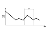
- FIG. 13 is an explanatory diagram showing an example of a change in SOC in the case of severity level C.
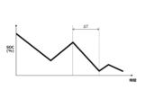
- FIG. 13 is an explanatory diagram showing an example of a change in SOC in the case of severity level B.
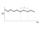
- FIG. 13 is an explanatory diagram showing an example of a change in SOC in the case of severity level A.
- FIG. 13 is an explanatory diagram showing an example of a change in SOC when a destination is not set.
- Figure 1 shows a schematic configuration of a series hybrid vehicle to which the present invention is applied.
- the series hybrid vehicle is configured with a power generating motor generator 1 that mainly operates as a generator, an internal combustion engine 2 used as a power generating internal combustion engine that drives the power generating motor generator 1 in response to a power generation request, a traveling motor generator 4 that mainly operates as a motor to drive the drive wheels 3, and a battery 5 consisting of a secondary battery such as a lithium ion battery (liquid lithium ion battery) or an all-solid-state battery that temporarily stores the generated power.
- the power generating motor generator 1 is driven by the internal combustion engine 2 via a gear train 10.
- the power obtained by the internal combustion engine 2 driving the power generating motor generator 1 is stored in the battery 5 via an inverter device (not shown).
- the traveling motor generator 4 is driven and controlled using the power of the battery 5.
- the power generated by the traveling motor generator 4 during regeneration is stored in the battery 5 via an inverter device (not shown).
- an inverter device not shown
- plug-in hybrid type configuration may be used in which the battery 5 can be charged from an external source such as a commercial power source.
- the operation of the motor generators 1 and 4, the charging and discharging of the battery 5, and the operation of the internal combustion engine 2 are controlled by a controller 6.
- the controller 6 is made up of multiple controllers connected so that they can communicate with each other, such as a motor controller 7 that controls the motor generators 1 and 4, an engine controller 8 that controls the internal combustion engine 2, and a battery controller 9 that manages the battery 5.
- Information such as the accelerator pedal opening and vehicle speed (not shown) is input to the controller 6.
- the battery controller 9 also calculates the SOC of the battery 5 based on the voltage and current of the battery 5.
- the battery 5 is also equipped with a battery temperature sensor 12 that detects the battery temperature.
- the vehicle is equipped with an outside air temperature sensor 13 that detects the outside air temperature.
- the controller 6 obtains information on the battery temperature and the outside air temperature from these sensors 12 and 13.
- the vehicle of one embodiment is equipped with a car navigation system 14 that uses so-called GPS, and is configured to provide route guidance by allowing the driver to set a desired destination.
- the map data provided by this car navigation system 14 includes road types (such as whether it is a highway or a general road), speed limits, gradient information, and the like.
- the vehicle of one embodiment is equipped with a communication device 11, as a so-called connected system, that communicates with a cloud server (not shown) and other vehicles traveling in the vicinity. It is possible to obtain information on the environment (weather, etc.) along the route, traffic congestion, and the like, via this communication device 11.
- the driving modes of such a series hybrid vehicle include an EV driving mode in which the vehicle runs on the power of the battery 5 without the combustion operation of the internal combustion engine 2 (i.e., power generation or charging), and an HEV driving mode in which the vehicle runs while generating power through the combustion operation of the internal combustion engine 2.
- the battery controller 9 manages the charging and discharging of the battery 5 so that the SOC of the battery 5 is kept between a predetermined SOC upper limit target value and a SOC lower limit target value. For example, if the SOC decreases due to EV driving and falls to the SOC lower limit target value, the internal combustion engine 2 is started via the engine controller 8 and the vehicle switches to HEV driving. Power generation by the internal combustion engine 2 ends, for example, when the SOC reaches the SOC upper limit target value. Regenerative power is also controlled by an appropriate method so that the SOC of the battery 5 does not exceed the SOC upper limit target value.
- the SOC lower limit target value is preset at multiple discrete levels according to the battery output to be guaranteed along the route, and one of the levels is selected depending on whether a destination is set in the car navigation system 14 and the predicted severity. Specifically, a first SOC lower limit target value, a second SOC lower limit target value, a third SOC lower limit target value, and a fourth SOC lower limit target value are set in order from highest SOC, and one of these is selectively used. At the highest first SOC lower limit target value, the highest battery output and therefore the vehicle driving force are guaranteed.
- an upper SOC target value is set for each level of the lower SOC target value, and the lower the level of the lower SOC target value, the lower the upper SOC target value.
- a first SOC upper target value, a second SOC upper target value, a third SOC upper target value, and a fourth SOC upper target value are set corresponding to the first to fourth SOC lower target values, respectively, and the fourth SOC upper target value is the lowest SOC.
- At least one of the first to fourth SOC lower limit target values and the corresponding first to fourth SOC upper limit target values may be corrected according to the temperature of the battery 5 so that the SOC control range between the SOC upper limit target value and the SOC lower limit target value becomes relatively wider on the high temperature side.
- the fourth SOC lower limit target value and the fourth SOC upper limit target value as an example, the higher the temperature of the battery 5, the lower the fourth SOC lower limit target value is made, and the fourth SOC upper limit target value is set to a constant value regardless of temperature, so that the higher the temperature, the wider the SOC control range becomes.
- the temperature of the battery 5 can be obtained by estimation based on the detection value of the battery temperature sensor 12, the detection value of the outside air temperature sensor 13, weather information obtained via the communication device 11, etc.
- step 1 it is determined whether a destination has been set in the car navigation system 14. If a destination has been set, the process proceeds to step 2, where various information about the route to the destination is obtained mainly from the car navigation system 14. This information includes, for example, the distance to the destination, the slope (gradient) of the roads along the route, the altitude, and whether the road is an ordinary road or an expressway.
- step 3 information about the weather, temperature, road congestion information, etc. along the route to the destination is obtained via the communication device 11, or the so-called Internet.
- step 4 the severity is determined based on the information obtained from the car navigation system 14 in step 2 and the environmental information obtained from the Internet in step 3.
- the severity is a numerical index that indicates the strictness of the requirements for the battery 5 for the route to the destination, and basically, the severity correlates with the maximum output required for the battery 5 predicted along the route from gradient information and vehicle speed information on the route. The greater the gradient, the higher the maximum output required for the battery 5, and the higher the vehicle speed on the highway, the higher the maximum output required for the battery 5. The higher the predicted maximum output required for the battery 5, the higher the severity.
- weather information particularly rainfall, snowfall, etc.
- the severity level is calculated by making corrections for road surface conditions.
- the battery characteristics shown in Figure 2 are taken into consideration, that is, the correlation between the SOC corresponding to the battery temperature and the battery output.
- Figure 2 shows three representative characteristic lines: characteristic L1 at room temperature (25°C), characteristic L2 at a relatively low temperature, and characteristic L3 at a relatively high temperature.
- characteristic lines L1, L2, and L3 the output of the battery 5 decreases as the SOC decreases.
- the relationship between the SOC and the output is correlated with the temperature of the battery 5, and the lower the temperature of the battery 5, the lower the output at the same SOC.
- the severity level thus quantified is compared in sequence with predetermined thresholds SHc and SHb (where SHc ⁇ SHb) in steps 5 and 6, and classified into three severity levels: A, B, and C. If the level is equal to or below the threshold SHc in step 5, the level is classified as the lowest severity level C, and the process proceeds to step 7, where the lowest fourth SOC lower limit target value and the corresponding fourth SOC upper limit target value are selected. If the level is equal to or below the threshold SHb in step 6, the level is classified as the intermediate severity level B, and the process proceeds to step 8, where the second lowest third SOC lower limit target value and the corresponding third SOC upper limit target value are selected. If the level exceeds the threshold SHb, the level is classified as the highest severity level A, and the process proceeds to step 9, where the second SOC lower limit target value and the corresponding second SOC upper limit target value are selected.
- SHc and SHb where SHc ⁇ SHb
- Step 10 the process proceeds from step 1 to step 10, and the severity level described above is calculated within the driver's expected driving range based on learning. For example, if a driver commutes from home to an office on a daily basis, it can be assumed that the driver will be heading to the same office based on the vehicle's start time of use and its location. Therefore, even if a destination is not set, the maximum output required by the battery 5 while driving is predicted within a relatively narrow distance range, and the severity level is calculated taking into account the battery characteristics as described above. Step 10 also obtains information on whether the driver has selected an acceleration-oriented mode, or so-called sports mode, as the vehicle's driving mode.
- step 11 it is determined whether the severity level is higher than the threshold SHc or the mode is sports mode. If the severity level is higher than the threshold SHc or the mode is sports mode, the process proceeds to step 12, where the highest first SOC lower limit target value and first SOC upper limit target value are selected. If the result in step 11 is NO, the process proceeds to step 5, where one of the second to fourth SOC lower limit target values and second to fourth SOC upper limit target values is selected depending on the severity level.
- At least one of the first to fourth SOC lower limit target values and the corresponding first to fourth SOC upper limit target values may be corrected depending on the temperature of the battery 5 so that the SOC control range between the SOC upper limit target value and the SOC lower limit target value becomes relatively wider on the high temperature side.
- the upper SOC target value may be variably set taking into account the travel distance to the destination, the predicted amount of regeneration on downhill roads, and the maximum required output of the battery predicted along the route to the destination based on gradient information and vehicle speed information.
- Figure 4 shows an example of the change in SOC during driving in the case of severity level C.
- the SOC decreases due to EV driving, and increases due to HEV driving and regeneration on downhill slopes.
- the broken line characteristic line in the figure is drawn typically for the purpose of explanation and is not necessarily accurate.
- the period ⁇ T in the figure typically indicates the maximum output period.
- the lowest fourth SOC lower limit target value and fourth SOC upper limit target value are selected among the multiple levels.
- the fourth SOC lower limit target value is set sufficiently low, the distance or time that EV driving can be continued is long. As a result, the frequency of power generation by the internal combustion engine 2 until the destination is reached is reduced, and the total fuel efficiency of EV driving and HEV driving combined is increased. It is also advantageous in reducing exhaust gas emissions.
- the SOC lower limit target value and the SOC upper limit target value are set low in this way, the impact of natural discharge when the vehicle has not been used for a long period of time becomes relatively large. Therefore, for example, when approaching the destination, the amount of power generation by the internal combustion engine 2 may be increased, and the SOC of the battery 5 may be controlled to be somewhat high when the vehicle is stopped.
- Figure 5 shows an example of changes in SOC while driving in the case of severity level B.
- the third SOC lower limit target value and the third SOC upper limit target value which are the second lowest among the multiple levels, are used, and EV driving continues after driving starts until the SOC drops to the third SOC lower limit target value. Therefore, the distance or time that EV driving can be continued after driving starts is relatively long.
- the SOC lower limit target value is higher than in the case of severity level C, so the guaranteed battery output while driving is higher than in the case of severity level C. Therefore, it is fully capable of handling a certain amount of uphill climbing and high-speed driving on the route.
- Figure 6 shows an example of changes in SOC while driving in the case of severity level A.
- a second SOC lower limit target value and a second SOC upper limit target value that are higher than those in the case of severity level B are selected. Therefore, the distance or time that EV driving can be continued after driving starts is relatively short.
- the SOC lower limit target value is higher than in the case of severity level B, the guaranteed battery output while driving is even higher than in the case of severity level B. Therefore, it is possible to reliably secure the battery output required for steep uphill climbs, etc. along the route.
- Figure 7 shows an example of the change in SOC while driving when there is no destination set and the severity level is higher than the threshold SHc, or when the vehicle is in sports mode.
- a first SOC lower limit target value and a first SOC upper limit target value that are higher than when a destination is set are used. This ensures that the battery output is always high, making it possible to handle so-called sports driving.
- the vehicle speed threshold value may be corrected based on the severity level described above. For example, the higher the severity level, the earlier the SOC can be restored by permitting operation of the internal combustion engine 2 at a relatively low vehicle speed.
- the driver may switch to sport mode.
- the settings are switched to the highest first SOC lower limit target value and first SOC upper limit target value as shown in FIG. 7, so that in many cases power generation by the internal combustion engine 2 is started, ensuring higher battery output.
- the driver may be presented with information, such as audio information, about the currently available maximum output and the time required to achieve the required output.
- the lowest level of the SOC lower limit target value that satisfies the required maximum output is selected based on the required maximum output of the battery 5 predicted along the route and the correlation between the SOC and battery output corresponding to the battery temperature.
- the present invention is not limited to the above embodiment, and various modifications are possible.
- the SOC lower limit target value is controlled in stages to simplify control, but the SOC lower limit target value may be configured to change continuously.
Landscapes
- Engineering & Computer Science (AREA)
- Mechanical Engineering (AREA)
- Transportation (AREA)
- Automation & Control Theory (AREA)
- Combustion & Propulsion (AREA)
- Chemical & Material Sciences (AREA)
- Physics & Mathematics (AREA)
- Mathematical Physics (AREA)
- Power Engineering (AREA)
- Human Computer Interaction (AREA)
- Life Sciences & Earth Sciences (AREA)
- Sustainable Energy (AREA)
- Sustainable Development (AREA)
- Electric Propulsion And Braking For Vehicles (AREA)
Priority Applications (4)
| Application Number | Priority Date | Filing Date | Title |
|---|---|---|---|
| EP23926632.3A EP4681984A4 (en) | 2023-03-13 | 2023-03-13 | METHOD FOR CONTROLLING A BATTERY IN A SERIES HYBRID VEHICLE AND A SERIES HYBRID VEHICLE |
| JP2025506273A JPWO2024189720A1 (https=) | 2023-03-13 | 2023-03-13 | |
| CN202380095100.4A CN120769812A (zh) | 2023-03-13 | 2023-03-13 | 串联式混合动力车辆的电池控制方法及串联式混合动力车辆 |
| PCT/JP2023/009511 WO2024189720A1 (ja) | 2023-03-13 | 2023-03-13 | シリーズハイブリッド車両のバッテリ制御方法およびシリーズハイブリッド車両 |
Applications Claiming Priority (1)
| Application Number | Priority Date | Filing Date | Title |
|---|---|---|---|
| PCT/JP2023/009511 WO2024189720A1 (ja) | 2023-03-13 | 2023-03-13 | シリーズハイブリッド車両のバッテリ制御方法およびシリーズハイブリッド車両 |
Publications (1)
| Publication Number | Publication Date |
|---|---|
| WO2024189720A1 true WO2024189720A1 (ja) | 2024-09-19 |
Family
ID=92754603
Family Applications (1)
| Application Number | Title | Priority Date | Filing Date |
|---|---|---|---|
| PCT/JP2023/009511 Ceased WO2024189720A1 (ja) | 2023-03-13 | 2023-03-13 | シリーズハイブリッド車両のバッテリ制御方法およびシリーズハイブリッド車両 |
Country Status (4)
| Country | Link |
|---|---|
| EP (1) | EP4681984A4 (https=) |
| JP (1) | JPWO2024189720A1 (https=) |
| CN (1) | CN120769812A (https=) |
| WO (1) | WO2024189720A1 (https=) |
Citations (5)
| Publication number | Priority date | Publication date | Assignee | Title |
|---|---|---|---|---|
| JP2002171603A (ja) | 2000-12-04 | 2002-06-14 | Matsushita Electric Ind Co Ltd | ハイブリッド自動車の制御装置 |
| JP2002345165A (ja) * | 2001-05-17 | 2002-11-29 | Toyota Motor Corp | 車両用電池制御装置及び方法 |
| JP2009044887A (ja) * | 2007-08-09 | 2009-02-26 | Toyota Motor Corp | 車両 |
| JP2015186985A (ja) * | 2014-03-27 | 2015-10-29 | トヨタ自動車株式会社 | ハイブリッド車両およびその制御方法 |
| WO2022175702A1 (ja) * | 2021-02-18 | 2022-08-25 | 日産自動車株式会社 | ハイブリッド車両制御方法及びハイブリッド車両制御装置 |
Family Cites Families (2)
| Publication number | Priority date | Publication date | Assignee | Title |
|---|---|---|---|---|
| KR20190010045A (ko) * | 2017-07-20 | 2019-01-30 | 현대자동차주식회사 | 친환경 차량의 충전 제어 장치, 그를 포함한 시스템 및 그 방법 |
| JP7143823B2 (ja) * | 2019-07-25 | 2022-09-29 | トヨタ自動車株式会社 | 車両の制御装置 |
-
2023
- 2023-03-13 JP JP2025506273A patent/JPWO2024189720A1/ja active Pending
- 2023-03-13 WO PCT/JP2023/009511 patent/WO2024189720A1/ja not_active Ceased
- 2023-03-13 CN CN202380095100.4A patent/CN120769812A/zh active Pending
- 2023-03-13 EP EP23926632.3A patent/EP4681984A4/en active Pending
Patent Citations (5)
| Publication number | Priority date | Publication date | Assignee | Title |
|---|---|---|---|---|
| JP2002171603A (ja) | 2000-12-04 | 2002-06-14 | Matsushita Electric Ind Co Ltd | ハイブリッド自動車の制御装置 |
| JP2002345165A (ja) * | 2001-05-17 | 2002-11-29 | Toyota Motor Corp | 車両用電池制御装置及び方法 |
| JP2009044887A (ja) * | 2007-08-09 | 2009-02-26 | Toyota Motor Corp | 車両 |
| JP2015186985A (ja) * | 2014-03-27 | 2015-10-29 | トヨタ自動車株式会社 | ハイブリッド車両およびその制御方法 |
| WO2022175702A1 (ja) * | 2021-02-18 | 2022-08-25 | 日産自動車株式会社 | ハイブリッド車両制御方法及びハイブリッド車両制御装置 |
Non-Patent Citations (1)
| Title |
|---|
| See also references of EP4681984A1 |
Also Published As
| Publication number | Publication date |
|---|---|
| EP4681984A4 (en) | 2026-03-18 |
| EP4681984A1 (en) | 2026-01-21 |
| CN120769812A (zh) | 2025-10-10 |
| JPWO2024189720A1 (https=) | 2024-09-19 |
Similar Documents
| Publication | Publication Date | Title |
|---|---|---|
| KR101713734B1 (ko) | 하이브리드 차량의 제어 방법 및 장치 | |
| CN102007031B (zh) | 车辆行驶控制系统 | |
| US6687581B2 (en) | Control device and control method for hybrid vehicle | |
| US8829848B2 (en) | Battery charging control device and battery charging control method for electric vehicle | |
| US7360615B2 (en) | Predictive energy management system for hybrid electric vehicles | |
| KR101836250B1 (ko) | 구동 모터를 구비한 차량의 dc 컨버터의 출력 전압을 제어하는 방법 및 장치 | |
| JP3610879B2 (ja) | ハイブリッド車両 | |
| EP3480076A1 (en) | Hybrid vehicle and method of changing operation mode for the same | |
| KR102477397B1 (ko) | 주행 제어 장치, 주행 제어 방법 및 비일시적 기억 매체 | |
| KR102444667B1 (ko) | 하이브리드 자동차 및 그를 위한 주행 모드 제어 방법 | |
| CN112937308B (zh) | 行驶控制装置、行驶控制方法、非临时性存储介质及车辆 | |
| KR20190069772A (ko) | 하이브리드 자동차 및 그를 위한 경로 탐색 방법 | |
| KR20190081379A (ko) | 하이브리드 차량의 배터리 soc 관리 방법 | |
| JP2001298805A (ja) | ハイブリッド車両の制御装置 | |
| JP2019085098A (ja) | ハイブリッド自動車及びそのためのモーター制御方法 | |
| JP6435789B2 (ja) | ハイブリッド駆動車両の出力制御装置 | |
| JP6012795B2 (ja) | ハイブリッド車両用エネルギーマネジメント装置 | |
| CN105564257B (zh) | 用于运行具有电蓄能器的机动车的方法和装置 | |
| KR20190008616A (ko) | 동적 교통정보를 이용한 친환경 차량의 타행 주행 제어 방법 | |
| JP6459453B2 (ja) | ハイブリッド車両の制御装置 | |
| JP2004178965A (ja) | 車両の制御装置 | |
| WO2024189720A1 (ja) | シリーズハイブリッド車両のバッテリ制御方法およびシリーズハイブリッド車両 | |
| KR102439628B1 (ko) | 하이브리드 차량의 주행 제어 방법 | |
| JP2017083999A (ja) | 車両の制御装置 | |
| JP7718168B2 (ja) | ハイブリッド車両の制御方法及びハイブリッド車両の制御装置 |
Legal Events
| Date | Code | Title | Description |
|---|---|---|---|
| 121 | Ep: the epo has been informed by wipo that ep was designated in this application |
Ref document number: 23926632 Country of ref document: EP Kind code of ref document: A1 |
|
| ENP | Entry into the national phase |
Ref document number: 2025506273 Country of ref document: JP Kind code of ref document: A |
|
| WWE | Wipo information: entry into national phase |
Ref document number: 2025506273 Country of ref document: JP |
|
| WWE | Wipo information: entry into national phase |
Ref document number: 202380095100.4 Country of ref document: CN |
|
| WWP | Wipo information: published in national office |
Ref document number: 202380095100.4 Country of ref document: CN |
|
| WWE | Wipo information: entry into national phase |
Ref document number: 2023926632 Country of ref document: EP |
|
| NENP | Non-entry into the national phase |
Ref country code: DE |
|
| ENP | Entry into the national phase |
Ref document number: 2023926632 Country of ref document: EP Effective date: 20251013 |
|
| ENP | Entry into the national phase |
Ref document number: 2023926632 Country of ref document: EP Effective date: 20251013 |
|
| ENP | Entry into the national phase |
Ref document number: 2023926632 Country of ref document: EP Effective date: 20251013 |
|
| ENP | Entry into the national phase |
Ref document number: 2023926632 Country of ref document: EP Effective date: 20251013 |
|
| ENP | Entry into the national phase |
Ref document number: 2023926632 Country of ref document: EP Effective date: 20251013 |
|
| WWP | Wipo information: published in national office |
Ref document number: 2023926632 Country of ref document: EP |