WO2024185752A1 - 劣化判定装置 - Google Patents
劣化判定装置 Download PDFInfo
- Publication number
- WO2024185752A1 WO2024185752A1 PCT/JP2024/008172 JP2024008172W WO2024185752A1 WO 2024185752 A1 WO2024185752 A1 WO 2024185752A1 JP 2024008172 W JP2024008172 W JP 2024008172W WO 2024185752 A1 WO2024185752 A1 WO 2024185752A1
- Authority
- WO
- WIPO (PCT)
- Prior art keywords
- switch
- value
- relay
- control unit
- determination device
- Prior art date
- Legal status (The legal status is an assumption and is not a legal conclusion. Google has not performed a legal analysis and makes no representation as to the accuracy of the status listed.)
- Ceased
Links
Images



Classifications
-
- B—PERFORMING OPERATIONS; TRANSPORTING
- B60—VEHICLES IN GENERAL
- B60L—PROPULSION OF ELECTRICALLY-PROPELLED VEHICLES; SUPPLYING ELECTRIC POWER FOR AUXILIARY EQUIPMENT OF ELECTRICALLY-PROPELLED VEHICLES; ELECTRODYNAMIC BRAKE SYSTEMS FOR VEHICLES IN GENERAL; MAGNETIC SUSPENSION OR LEVITATION FOR VEHICLES; MONITORING OPERATING VARIABLES OF ELECTRICALLY-PROPELLED VEHICLES; ELECTRIC SAFETY DEVICES FOR ELECTRICALLY-PROPELLED VEHICLES
- B60L3/00—Electric devices on electrically-propelled vehicles for safety purposes; Monitoring operating variables, e.g. speed, deceleration or energy consumption
-
- B—PERFORMING OPERATIONS; TRANSPORTING
- B60—VEHICLES IN GENERAL
- B60L—PROPULSION OF ELECTRICALLY-PROPELLED VEHICLES; SUPPLYING ELECTRIC POWER FOR AUXILIARY EQUIPMENT OF ELECTRICALLY-PROPELLED VEHICLES; ELECTRODYNAMIC BRAKE SYSTEMS FOR VEHICLES IN GENERAL; MAGNETIC SUSPENSION OR LEVITATION FOR VEHICLES; MONITORING OPERATING VARIABLES OF ELECTRICALLY-PROPELLED VEHICLES; ELECTRIC SAFETY DEVICES FOR ELECTRICALLY-PROPELLED VEHICLES
- B60L50/00—Electric propulsion with power supplied within the vehicle
- B60L50/50—Electric propulsion with power supplied within the vehicle using propulsion power supplied by batteries or fuel cells
- B60L50/60—Electric propulsion with power supplied within the vehicle using propulsion power supplied by batteries or fuel cells using power supplied by batteries
-
- B—PERFORMING OPERATIONS; TRANSPORTING
- B60—VEHICLES IN GENERAL
- B60L—PROPULSION OF ELECTRICALLY-PROPELLED VEHICLES; SUPPLYING ELECTRIC POWER FOR AUXILIARY EQUIPMENT OF ELECTRICALLY-PROPELLED VEHICLES; ELECTRODYNAMIC BRAKE SYSTEMS FOR VEHICLES IN GENERAL; MAGNETIC SUSPENSION OR LEVITATION FOR VEHICLES; MONITORING OPERATING VARIABLES OF ELECTRICALLY-PROPELLED VEHICLES; ELECTRIC SAFETY DEVICES FOR ELECTRICALLY-PROPELLED VEHICLES
- B60L58/00—Methods or circuit arrangements for monitoring or controlling batteries or fuel cells, specially adapted for electric vehicles
- B60L58/10—Methods or circuit arrangements for monitoring or controlling batteries or fuel cells, specially adapted for electric vehicles for monitoring or controlling batteries
-
- G—PHYSICS
- G01—MEASURING; TESTING
- G01R—MEASURING ELECTRIC VARIABLES; MEASURING MAGNETIC VARIABLES
- G01R31/00—Arrangements for testing electric properties; Arrangements for locating electric faults; Arrangements for electrical testing characterised by what is being tested not provided for elsewhere
- G01R31/327—Testing of circuit interrupters, switches or circuit-breakers
-
- H—ELECTRICITY
- H01—ELECTRIC ELEMENTS
- H01H—ELECTRIC SWITCHES; RELAYS; SELECTORS; EMERGENCY PROTECTIVE DEVICES
- H01H47/00—Circuit arrangements not adapted to a particular application of the relay and designed to obtain desired operating characteristics or to provide energising current
-
- H—ELECTRICITY
- H02—GENERATION; CONVERSION OR DISTRIBUTION OF ELECTRIC POWER
- H02H—EMERGENCY PROTECTIVE CIRCUIT ARRANGEMENTS
- H02H3/00—Emergency protective circuit arrangements for automatic disconnection directly responsive to an undesired change from normal electric working condition with or without subsequent reconnection ; integrated protection
Definitions
- This disclosure relates to a deterioration determination device.
- Patent document 1 discloses a technology that optimizes the degree of relay deterioration by adjusting the precharge time when the inverter is precharged by a precharge circuit.
- a more direct way to determine whether a relay is degraded is to measure the resistance between both terminals of the relay and use the change in resistance over time. Specifically, it is known that as a relay deteriorates, its resistance increases, and this phenomenon can be used to determine whether a relay is degraded. However, when a relay is repeatedly turned on and off, the smoothness of the surface of the contacts inside the relay is lost, making the state of contact of the contacts more likely to vary, and the resistance value each time it is turned on and off also more likely to vary. For this reason, there is a need for technology that can determine whether a relay is degraded in a way that reduces the effect of variations in the resistance value each time it is turned on and off.
- This disclosure has been made based on the above-mentioned circumstances, and aims to provide a deterioration determination device that can appropriately determine whether or not a relay is in a deteriorated state.
- the deterioration determination device of the present disclosure is A deterioration determination device for use in an in-vehicle system including a power path that is a path for transmitting power from a power supply unit to a load and a relay provided in the power path, a control unit that measures a resistance value of the relay every time a measurement condition is satisfied, The control unit determines whether or not the relay is in a deteriorated state based on the average resistance value.
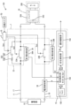
- FIG. 1 is a circuit diagram illustrating an example of an in-vehicle system including a deterioration determination device according to a first embodiment.
- FIG. 2 is a flowchart showing an example of control of the control unit in the deterioration determining device of the first embodiment.
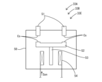
- FIG. 3 is a schematic diagram showing an example of the structure of a relay.
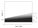
- FIG. 4 is a graph showing the change in resistance of a relay when the relay is repeatedly switched between the on and off states.
- FIG. 5 is a circuit diagram illustrating an in-vehicle system including the deterioration determination device of the second embodiment.
- FIG. 6 is a flowchart showing an example of control by the control unit in the deterioration determining device of the second embodiment.
- a deterioration determination device for use in an in-vehicle system including a power path that is a path for transmitting power from a power supply unit to a load and a relay provided in the power path, a control unit that measures a resistance value of the relay every time a measurement condition is satisfied, The control unit determines whether the relay is in a deteriorated state based on the average resistance value.
- the deterioration determination device of (1) can suppress the influence of the variation in the magnitude of the resistance value each time the relay is turned on and off by using the average resistance value. Therefore, with this configuration, it is easy to determine whether the relay is in a deteriorated state while suppressing the influence of the variation in the magnitude of the resistance value each time the relay is turned on and off.
- the measurement condition includes a condition that the relay is switched from off to on
- the control unit determines whether the relay is in a deteriorated state based on an average value of a plurality of the resistance values measured during a plurality of on periods sandwiching an off period of the relay.
- the deterioration determination device of (2) measures the resistance value when the relay switches from off to on. Each time the relay switches from off to on, the contact position where the contact surfaces of the contacts touch each other changes slightly, and the roughness of the contact surfaces changes depending on the current flowing. Therefore, with this configuration, the magnitude of each resistance value varies due to the above-mentioned changes, so by using an average value calculated taking into account this variation, it is possible to determine whether the relay is in a deteriorated state while taking into account the actual condition of the relay.
- the control unit determines whether the relay is in a deteriorated state based on the average resistance value.
- the deterioration determination device of (3) is configured to measure the resistance value when the start switch switches from off to on or on to off, so the resistance value tends to stabilize.
- a deterioration determination device in which the control unit determines whether the relay is in a deteriorated state based on a standard deviation value calculated using the average resistance value.
- the resistance value of a relay tends to increase as the number of times it is turned on and off increases, and the variation in the value increases with each on and off. For this reason, the deterioration determination device of (4) uses a standard deviation value calculated using the average resistance value of such characteristics, and is therefore able to accurately grasp the above trend and determine whether or not the relay is in a deteriorated state, without being limited by the variation in the resistance value of the relay.
- a deterioration determination device in which the control unit determines whether the relay is in a deteriorated state based on the moving average value of the resistance value.
- the deterioration determination device can determine whether a relay is in a deteriorated state by a simple calculation called a moving average.
- the control unit determines whether the relay is in a deteriorated state based on the average resistance value that is equal to or greater than a lower threshold value.
- a deterioration determination device A deterioration determination device.
- the deterioration determination device (6) is configured to extract the resistance value that increases as the relay deteriorates using a lower threshold value, and use the extracted resistance value as an average value, so that it is possible to determine whether the relay is in a deteriorated state while focusing on the deterioration of the relay.
- a deterioration determination device in which the control unit performs an abnormality response process when it is determined that the relay is in a deteriorated state.
- the deterioration determination device (7) performs an abnormality response process, making it easier to take appropriate action when the resistance value exceeds a threshold value (i.e., the relay is deteriorated).
- the in-vehicle system 100 shown in Fig. 1 is a power supply system mounted on a vehicle, and includes a power supply unit 10, a power path 11, a system main relay 33, and a deterioration determination device 1.
- the deterioration determination device 1 includes a current detection unit 38, a potential detection unit 39, and a control unit 15.
- the deterioration determination device 1 is used in the in-vehicle system 100.
- the potential detection unit 39 includes a first potential detection unit 39A and a second potential detection unit 39B.
- the in-vehicle system 100 is configured to be able to supply power from the power supply unit 10 to the load 35 via the power path 11, which is a path along which power is transmitted between the power supply unit 10 and the load 35.
- the power supply unit 10 is a battery capable of supplying power to the load 35.
- the power supply unit 10 may be, for example, a lead battery or a battery pack formed by combining multiple single cells, such as lithium ion batteries or nickel hydride batteries, in series.
- the power path 11 includes a positive power line 17 and a negative power line 20.
- the positive power line 17 is electrically connected to the high potential terminal of the power supply unit 10.
- the output voltage of the power supply unit 10 is applied to the positive power line 17.
- the negative power line 20 is electrically connected to the low potential terminal of the power supply unit 10.
- the negative power line 20 has a lower potential than the positive power line 17.
- the low potential terminal of the power supply unit 10 is electrically connected to, for example, the metal body of the vehicle and is at the same potential as the metal body of the vehicle.
- the output voltage of the power supply unit 10 corresponds to the potential difference between the high potential terminal and the low potential terminal.
- the power path 11 is a path that transmits power from the power supply unit 10 to the load 35.
- connection objects preferably means a configuration in which the connection objects are connected in a mutually conductive state (a state in which current can flow) so that the potentials of both connection objects are equal.
- electrically connected may also mean a configuration in which the connection objects are connected in a state in which they can be conductive with an electrical component interposed between them.
- a load 35 is electrically connected to the positive power line 17 and the negative power line 20.
- the load 35 is an electronic component for vehicle use, and is applicable to products such as electric components, ECUs, and ADAS target components.
- the load 35 includes an inverter 35A having a capacitor 35C, and a motor 35B.
- the capacitor 35C smoothes the voltage based on the power supply unit 10 and supplies it to the inverter 35A.
- the inverter 35A is electrically connected to the power path 11.
- the inverter 35A generates an AC voltage (e.g., three-phase AC) from a DC voltage based on the voltage supplied from the power supply unit 10, and supplies it to the motor 35B.
- the motor 35B is, for example, a main motor.
- the motor 35B rotates based on the power supplied from the power supply unit 10, and provides a rotational force to the wheels of the vehicle.
- the current output from the high-potential terminal of the power supply unit 10 flows in the following order: positive power line 17, load 35, negative power line 20, and the low-potential terminal of the power supply unit 10.
- the system main relay 33 is provided between the power supply unit 10 and the load 35, interposed between the positive power line 17 and the negative power line 20.
- the system main relay 33 has a first switch 33A which is a relay, a second switch 33B which is a relay, and a parallel switching path 33C.
- the first switch 33A and the second switch 33B are mechanical relay switches having internal contacts that physically switch between a contacted state and a separated state, for example.
- the parallel switching path 33C has a resistor 33D and a third switch 33E which is a relay connected in series to the resistor 33D.
- the third switch 33E is a mechanical relay switch having a configuration similar to that of the first switch 33A and the second switch 33B.
- the third switch 33E is a so-called precharge relay.
- the structures of the first contactor 33A, the second contactor 33B, and the third contactor 33E will be described.
- the first contactor 33A, the second contactor 33B, and the third contactor 33E are provided so that a pair of terminal portions 51 protrude from a synthetic resin case 50.
- the positive power line 17 or the negative power line 20 is electrically connected to these terminal portions 51.
- the case 50 is provided with a movable contact 52 that can electrically contact each of the pair of terminal portions 51.
- An iron core 53 is attached to the movable contact 52.
- a coil 54 is arranged around the iron core 53 so as to surround the iron core 53.
- the first switch 33A is provided on the positive power line 17.
- the second switch 33B is provided on the negative power line 20.
- the resistor 33D and the third switch 33E of the parallel switching path 33C are electrically connected to the positive power line 17 so as to be in parallel with the first switch 33A.
- the parallel switching path 33C is a so-called pre-charge circuit.
- the first switch 33A, the second switch 33B, and the third switch 33E are controlled to switch between an on state and an off state by a predetermined control device C (hereinafter also simply referred to as control device C).
- the control device C is configured as, for example, a microcomputer, and includes a CPU, ROM, RAM, non-volatile memory, etc.
- the control device C is included in the configuration of the control unit 15.
- the first switch 33A, the second switch 33B, and the third switch 33E switch between an on state and an off state to switch the power path 11 between a conductive state and a cut-off state.
- the current detection unit 38 is disposed on the negative power line 20 closer to the power supply unit 10 than the second switch 33B.
- the current detection unit 38 has, for example, a resistor and a differential amplifier, and is configured to be able to output a value indicating the current flowing through the negative power line 20 (specifically, an analog voltage corresponding to the value of the current flowing through the negative power line 20) as a current value A.
- the current detection unit 38 detects the current state of the current flowing through the power path 11 as a current value A.
- the first potential detection unit 39A is configured, for example, as a potential detection circuit.
- the first potential detection unit 39A is configured to detect a first potential at the terminal on the power supply unit 10 side, which is one end terminal of the first switch 33A, and a second potential at the terminal on the load 35 side, which is the other end terminal, and output a potential difference V1 between these first and second potentials.
- the first potential detection unit 39A detects the potential difference V1 between both the terminals on the power supply unit 10 side and the load 35 side of the first switch 33A (the terminals on both sides, the side where power is supplied to the first switch 33A and the side where power is output).
- the second potential detection unit 39B is configured, for example, as a potential detection circuit similar to the first potential detection unit 39A.
- the second potential detection unit 39B is configured to detect a first voltage at the terminal on the power supply unit 10 side, which is one end terminal of the second switch 33B, and a second potential at the terminal on the load 35 side, which is the other end terminal, and output a potential difference V2 between these first and second potentials.
- the second potential detection unit 39B detects the potential difference V2 between both the terminals on the power supply unit 10 side and the load 35 side of the second switch 33B (the terminals on both sides, the side where power is supplied to the second switch 33B and the side where power is output).
- the potential differences V1 and V2 between the first potential and the second potential may be values calculated by an analog circuit (e.g., a differential amplifier circuit), or may be values calculated by a digital circuit after AD conversion of the first potential and the second potential, respectively.
- an analog circuit e.g., a differential amplifier circuit
- a digital circuit after AD conversion of the first potential and the second potential, respectively.
- the control unit 15 is configured, for example, as a microcomputer, and includes a CPU, a ROM, a RAM, and a storage unit 15D configured with a non-volatile memory, etc.
- the control unit 15 includes a resistance value calculation unit 15A, a deterioration detection unit 15B, and a notification function unit 15C.
- the resistance value calculation unit 15A is configured to receive the current value A, potential difference V1, and potential difference V2 from the current detection unit 38, the first potential detection unit 39A, and the second potential detection unit 39B, respectively.
- the resistance value calculation unit 15A calculates the resistance value R1 of the first switch 33A and the resistance value R2 of the second switch 33B based on these values (current value A, potential differences V1, V2).
- calculating and determining the resistance values R1, R2 is the same as measuring the resistance values R1, R2.
- the resistance value R1 of the first switch 33A is determined by dividing the potential difference V1 by the current value A.
- the resistance value R2 of the second switch 33B is determined by dividing the potential difference V2 by the current value A.
- the control unit 15 calculates the resistance values R1 and R2 of the first switch 33A and the second switch 33B based on the potential differences V1 and V2 between the first potential and the second potential.
- the resistance value calculation unit 15A of the control unit 15 In order for the resistance value calculation unit 15A of the control unit 15 to measure the resistance values R1 and R2, the measurement condition that the first switch 33A and the second switch 33B are switched to the on state must be met.
- the resistance value calculation unit 15A stores the calculated resistance values R1 and R2 in the memory unit 15D.
- the resistance values R1 and R2 are stored separately from each other in the memory unit 15D.
- the resistance value calculation unit 15A calculates the resistance values R1 and R2 when a predetermined short time has elapsed after the vehicle start switch 70 is switched from off to on, switching the first switch 33A and the second switch 33B to on.
- the control unit 15 then stores the resistance values R1 and R2 calculated by the resistance value calculation unit 15A in the memory unit 15D.
- the resistance values R1 and R2 are stored in the memory unit 15D every time the vehicle start switch 70 is switched from off to on.
- the number of resistance values R1 and R2 stored in the memory unit 15D is limited to a predetermined number.
- the memory unit 15D that has stored a predetermined number of resistance values R1 and R2 is configured to erase the oldest stored resistance values R1 and R2 and then store the newly calculated resistance values R1 and R2.
- the standard deviation value De is calculated using the multiple resistance values R1, R2 stored in the storage unit 15D, using the formula 1 shown below. Specifically, the standard deviation value De is a standard deviation value De1 calculated using the resistance value R1, and a standard deviation value De2 calculated using the resistance value R2.
- n is the number of each resistance value R1 (R2) stored in the memory unit 15D
- i is the order of the resistance value R1 (R2) stored in the memory unit 15D
- Ri is the i-th resistance value R1 (R2) stored in the memory unit 15D.
- Ra is the average value of the resistance values R1 (R2) stored in the memory unit 15D.
- the average value Ra is the average value Ra1 of the resistance values R1 and the average value Ra2 of the resistance values R2.
- the resistance values R1 and R2 gradually increase as the current is repeatedly applied and stopped between the pair of terminal parts 51 and the movable contact 52, and the width of the variation S also increases as the number of times the state switches between the on state and the off state increases (see Figures 3 and 4).
- the standard deviation value De (De1, De2) gradually increases each time it is calculated (i.e., each time the vehicle start switch 70 switches from off to on).
- the standard deviation value De (De1, De2) increases as the degree of deterioration of the first switch 33A and the second switch 33B progresses. Therefore, the standard deviation value De (De1, De2) can be used as a value indicating the degree of deterioration of the first switch 33A and the second switch 33B.
- the deterioration detection unit 15B is configured to be able to execute a deterioration determination process.
- the deterioration determination process is a process of comparing the standard deviation value De1 calculated by the resistance value calculation unit 15A with the standard deviation threshold value Th11 stored in the memory unit 15D, and comparing the standard deviation value De2 with the standard deviation threshold value Th12 stored in the memory unit.
- the deterioration detection unit 15B is configured to output a deterioration signal Sd when it determines that the standard deviation value De1 exceeds the standard deviation threshold value Th11 or that the standard deviation value De2 exceeds the standard deviation threshold value Th12.
- the deterioration signal Sd is output when the first switch 33A or the second switch 33B is in a deteriorated state.
- the control unit 15 determines that the first switch 33A is in a deteriorated state when the standard deviation value De1 exceeds the standard deviation threshold value Th11, and determines that the second switch 33B is in a deteriorated state when the standard deviation value De2 exceeds the standard deviation threshold value Th12.
- the deterioration detection unit 15B determines in the deterioration determination process that the magnitude of the standard deviation value De1 is equal to or less than the standard deviation threshold value Th11 and the magnitude of the standard deviation value De2 is equal to or less than the standard deviation threshold value Th12, the deterioration detection unit 15B does not output the deterioration signal Sd. In this case, the control unit 15 determines that the first switch 33A and the second switch 33B are not in a deteriorated state. In this way, the control unit 15 determines the degree of deterioration of the first switch 33A and the second switch 33B based on the standard deviation value De (De1, De2) calculated using the average value Ra (Ra1, Ra2) of the resistance values R1 and R2.
- the notification function unit 15C is configured to perform an abnormality response process by transmitting information to an external device (not shown) such as a BMS (battery management system) based on the degradation signal Sd input from the degradation detection unit 15B.
- the control unit 15 performs an abnormality response process when the standard deviation value De1 exceeds the standard deviation threshold value Th11, or when the standard deviation value De2 exceeds the standard deviation threshold value Th12.
- step S1 is executed to switch the start switch 70 from off to on.
- step S2 an on signal Son (see FIG. 1) is output from the control device C, and switching control is executed in which the first switch 33A, the second switch 33B, and the third switch 33E are switched from off to on based on the on signal Son.
- the switching control the first switch 33A is turned off while the second switch 33B and the third switch 33E are turned on to start energizing the power path 11, and then the first switch 33A is switched on while maintaining the second switch 33B and the third switch 33E in the on state. In other words, the first switch 33A is switched from off to on after the second switch 33B.
- the power path 11 starts to be energized. Since the resistor 33D is connected in series to the third switch 33E, the current starts to flow slowly in the power path 11 so that it gradually increases.
- the power path 11 is in a conductive state that allows power to be supplied from the power supply unit 10 to the load 35.
- an inrush current immediately flows through the first switch 33A.
- a current rise occurs in which the current value A flowing through the power path 11 rises suddenly. In this way, the switching control is executed, and the power path 11 starts to pass current or a current rise occurs.
- the inrush current continues to flow for a predetermined short time after the first switch 33A is switched to the on state, and after the predetermined short time has elapsed, the current flowing through the first switch 33A settles to remain within a predetermined range that is smaller than the magnitude of the inrush current. In this way, the first switch 33A is switched to the on state, and current flows through the power path 11.
- the control unit 15 has a timer function and starts measuring a predetermined short period of time from when the current value A changes from 0 to a predetermined magnitude.
- the predetermined short period of time is the time it takes for the current flowing through the first switch 33A to settle into a predetermined range that is smaller than the magnitude of the inrush current.
- Step S4 is a process for waiting for the predetermined short time to elapse, thereby waiting for the current flowing through the first switch 33A to settle within a predetermined range that is smaller than the magnitude of the inrush current. For example, when the control unit 15 determines in step S4 that the predetermined short time has not elapsed since the current value A in the power path 11 changed from 0 to the predetermined magnitude (No in step S4), the control unit 15 proceeds again to step S3. When the process proceeds again to step S3, the control unit 15 advances the count of a timer it has, and then repeats the process of step S4 again.
- step S4 if the control unit 15 determines that a predetermined short time has elapsed since the current value A in the power path 11 changed from 0 to a predetermined magnitude (Yes in step S4), the process proceeds to step S5.
- the control unit 15 calculates the resistance values R1 and R2 in the resistance value calculation unit 15A based on the current value A and the potential differences V1 and V2 input from each of the current detection unit 38, the first potential detection unit 39A, and the second potential detection unit 39B. The process then proceeds to step S6.
- the control unit 15 stores the calculated resistance values R1 and R2 in the memory unit 15D. At this time, if the number of each of the resistance values R1 and R2 stored in the memory unit 15D is a predetermined number, the oldest stored resistance values R1 and R2 are erased, and the calculated resistance values R1 and R2 are stored in the memory unit 15D.
- control unit 15 calculates the standard deviation value De (De1, De2) in the resistance value calculation unit 15A based on the formula shown in Equation 1 using the resistance values R1 and R2 stored in the memory unit 15D.
- Step S8 is a process for determining whether or not each of the first switch 33A and the second switch 33B is in a deteriorated state.
- the deterioration determination process determines that the standard deviation value De1 is smaller than the standard deviation threshold value Th11 and that the standard deviation value De2 is smaller than the standard deviation threshold value Th12 (No in step S8), the deterioration signal Sd is not output and the process shown in FIG. 2 is terminated.
- the notification function unit 15C transmits information to an external device (not shown).
- the standard deviation values De1, De2 exceed the standard deviation threshold values Th11, Th12 (i.e., when it is determined that either the first switch 33A or the second switch 33B is in a deteriorated state)
- the notification function unit 15C of the control unit 15 performs an abnormality response process to notify the outside that a deterioration state has occurred. In this way, the process shown in FIG. 2 ends.
- step S5 to step S9 may be executed when the start switch 70 is switched from on to off. Specifically, the start switch 70 is switched from on to off. Then, the control unit 15 executes the processes from step S5 to step S9. Thereafter, the output of the on signal Son from the control device C is stopped. As a result, the first switch 33A, the second switch 33B, and the third switch 33E are switched from the on state to the off state. Thus, when the start switch 70 is switched from on to off, the first switch 33A and the second switch 33B are switched off.
- the measurement conditions under which the control unit 15 measures the resistance values R1 and R2 may include the conditions when the start switch 70 is switched from on to off.
- step S5 to step S9 may be performed when the start switch 70 is on and the vehicle is stopped.
- the deterioration determination device 1 is used in an in-vehicle system 100 that includes a power path 11, which is a path for transmitting power from a power source unit 10 to a load 35, and a first switch 33A and a second switch 33B provided on the power path 11.
- the deterioration determination device 1 includes a control unit 15 that measures the resistance values R1, R2 of the first switch 33A and the second switch 33B each time a measurement condition is satisfied, and the control unit 15 determines whether or not each of the first switch 33A and the second switch 33B is in a deteriorated state based on the average values Ra1, Ra2 of the resistance values R1, R2.
- the deterioration determination device 1 can suppress the influence of the variation in the magnitude of the resistance values R1, R2 each time they are turned on and off by using the average values Ra1, Ra2 of the resistance values R1, R2. Therefore, with this configuration, it is easy to determine whether or not each of the first switch 33A and the second switch 33B is in a deteriorated state while suppressing the influence of the variation in the magnitude of the resistance values R1, R2 each time they are turned on and off.
- the measurement conditions include a condition that the first switch 33A and the second switch 33B are switched from off to on.
- the control unit 15 measures the resistance values R1, R2 each time the first switch 33A and the second switch 33B are switched from off to on, and determines whether or not each of the first switch 33A and the second switch 33B is in a deteriorated state based on the average values Ra1, Ra2 of the multiple measured resistance values R1, R2.
- the resistance values R1 and R2 are measured while the start switch 70 is off.
- the contact surface Cs of the terminal portion 51 and the movable contact 52 of the first switch 33A and the second switch 33B change from a non-contact state to a contact state, the contact position on the contact surface Cs changes slightly, and the roughness of the contact surface Cs changes depending on the current flowing. Therefore, according to this configuration, the magnitude of each resistance value R1 and R2 varies due to the above-mentioned changes.
- the first switch 33A and the second switch 33B are turned on when the vehicle's start switch 70 is switched on, and turned off when the start switch 70 is switched off.
- the measurement conditions include at least one of the conditions when the start switch 70 is switched from off to on, or when it is switched from on to off.
- the control unit 15 determines whether or not each of the first switch 33A and the second switch 33B is in a deteriorated state based on the average values Ra1 and Ra2 of the resistance values R1 and R2.
- the start switch 70 switches from off to on or from on to off, a predetermined sequence is executed, and the magnitude of the current flowing through the power path 11 tends to stabilize. Therefore, with this configuration, the resistance values R1 and R2 are measured at least when the start switch 70 switches from off to on or from on to off, so the resistance values R1 and R2 tend to stabilize.
- the control unit 15 of the deterioration determination device 1 determines whether or not the first switch 33A and the second switch 33B are in a deteriorated state based on the standard deviation values De1 and De2 calculated using the average values Ra1 and Ra2 of the resistance values R1 and R2.
- the resistance values R1, R2 of the first switch 33A and the second switch 33B have a characteristic that they become larger and more variable as the number of on/off cycles increases.
- the deterioration determination device 1 uses standard deviation values De1, De2 calculated using average values Ra1, Ra2 of the resistance values R1, R2 of such characteristics, so that it can determine whether or not each of the first switch 33A and the second switch 33B is in a deteriorated state while taking into account the actual conditions of the first switch 33A and the second switch 33B, without being limited by the variation in the resistance values R1, R2 of the first switch 33A and the second switch 33B.
- the control unit 15 of the deterioration determination device 1 performs an abnormality response process when it is determined that the standard deviation values De1, De2 exceed the threshold value and the first switch 33A and the second switch 33B are in a deteriorated state.
- the control unit 15 of the deterioration determination device 1 performs an abnormality response process when it is determined that the standard deviation values De1, De2 exceed the threshold value and the first switch 33A and the second switch 33B are in a deteriorated state.
- the deterioration determination device 2 provided in the in-vehicle system 200 of the second embodiment differs from the first embodiment in that the control unit 15 compares the calculated resistance values R1, R2 with a lower threshold value Th23, and stores the resistance values R1, R2 equal to or greater than the lower threshold value Th23 in the memory unit 15D, calculates a moving average value Ma, and stores moving average threshold values Th21, Th22 in the memory unit 15D, but is otherwise common to the first embodiment.
- the same components as those in the first embodiment are denoted by the same reference numerals, and detailed description thereof will be omitted.
- the resistance value calculation unit 15A compares the resistance values R1 and R2 calculated using the current value A and the potential differences V1 and V2 with the lower threshold value Th23.
- the lower threshold value Th23 is stored in the memory unit 15D (see FIG. 5).
- the lower threshold value Th23 is a value greater than 0 ⁇ .
- the resistance values R1 and R2 calculated each time the on state and the off state are repeatedly switched fall within the range of variation S. More specifically, these resistance values R1 and R2 fall within the lower range L of the range of variation S more frequently, and fall within a range U above the lower range L less frequently. Therefore, even if one focuses on the resistance values R1 and R2 falling within the lower range L, it is difficult to determine whether or not each of the first switch 33A and the second switch 33B is in a deteriorated state.
- the lower threshold value Th23 is set to a value equivalent to the boundary between the lower range L and the upper range U.
- the lower threshold value Th23 is set to a value that is greater than the lower limit of the range of the variation S and smaller than the upper limit of the range of the variation S.
- the resistance value calculation unit 15A excludes the resistance values R1, R2 that are smaller than the lower threshold value Th23 and stores the resistance values R1, R2 that are equal to or greater than the lower threshold value Th23 in the storage unit 15D. Note that the resistance values R1, R2 are stored separately from each other.
- the lower threshold value Th23 may be set by the designer based on the experimentally obtained graph as shown in FIG. 4, or it may be the average or standard deviation of all the values plotted on the experimentally obtained graph as shown in FIG. 4.
- the resistance value calculation unit 15A calculates the resistance values R1, R2 when a predetermined short time has elapsed after the first switch 33A and the second switch 33B are switched on as a result of the vehicle's start switch 70 being switched from off to on.
- the resistance value calculation unit 15A compares the calculated resistance values R1, R2 with the lower threshold value Th23, and stores the resistance values R1, R2 that are equal to or greater than the lower threshold value Th23 in the memory unit 15D.
- the resistance values R1, R2 that are equal to or greater than the lower threshold value Th23 are stored in the memory unit 15D every time the vehicle's start switch 70 is switched from off to on.
- the number of each of the resistance values R1, R2 stored in the memory unit 15D is limited to a predetermined number.
- the memory unit 15D that stores a predetermined number of resistance values R1 and R2 is configured to erase the oldest stored resistance values R1 and R2 and then store newly calculated resistance values R1 and R2.
- a moving average value Ma is calculated using the multiple resistance values R1, R2 stored in the storage unit 15D, using the formula 2 shown below.
- n is the number of resistance values R1 (R2) stored in memory unit 15D
- i is the order of resistance values R1 (R2) stored in memory unit 15D
- Ri is the i-th resistance value R1 (R2) stored in memory unit 15D.
- the moving average value Ma (Ma1, Ma2) increases as the degree of deterioration of each of the first switch 33A and the second switch 33B progresses. Therefore, the moving average value Ma (Ma1, Ma2) can be used as a value indicating the degree of deterioration of each of the first switch 33A and the second switch 33B.
- the degradation detection unit 15B compares the moving average value Ma1 calculated by the resistance value calculation unit 15A with the moving average threshold value Th21 (see FIG. 5) stored in the memory unit 15D, and compares the moving average value Ma2 with the moving average threshold value Th22 (see FIG. 5) stored in the memory unit 15D.
- the deterioration detection unit 15B is configured to be able to output a deterioration signal Sd when it determines that the moving average value Ma1 exceeds the moving average threshold value Th21 or that the moving average value Ma2 exceeds the moving average threshold value Th22. That is, the control unit 15 determines that the first switch 33A is in a deteriorated state when the moving average value Ma1 exceeds the moving average threshold value Th21, and determines that the second switch 33B is in a deteriorated state when the moving average value Ma2 exceeds the moving average threshold value Th22.
- the control unit 15 determines that the first switch 33A and the second switch 33B are not in a deteriorated state. In this way, the control unit 15 determines whether or not each of the first switch 33A and the second switch 33B is in a deteriorated state based on the moving average value Ma (Ma1, Ma2) calculated based on the resistance values R1 and R2 that are equal to or greater than the lower threshold value Th23.
- the control unit 15 calculates the resistance values R1 and R2 in the resistance value calculation unit 15A based on the current value A and the potential differences V1 and V2 input from the current detection unit 38, the first potential detection unit 39A, and the second potential detection unit 39B (step S5). Then, the process proceeds to step S10.
- the resistance value calculation unit 15A of the control unit 15 determines whether the calculated resistance values R1 and R2 are equal to or greater than the lower threshold value Th23. If the resistance value calculation unit 15A determines in step S10 that the calculated resistance values R1 and R2 are smaller than the lower threshold value Th23, the process shown in FIG. 6 is terminated.
- step S10 determines in step S10 that the calculated resistance values R1 and R2 are equal to or greater than the lower threshold value Th23
- the process proceeds to step S16, where the control unit 15 stores the calculated resistance values R1 and R2 in the memory unit 15D. In this way, only the resistance values R1 and R2 equal to or greater than the lower threshold value Th23 are stored in the memory unit 15D.
- control unit 15 calculates the moving average value Ma (Ma1, Ma2) in the resistance value calculation unit 15A based on the formula shown in Equation 2 using the resistance values R1 and R2 stored in the memory unit 15D.
- the control unit 15 executes a deterioration determination process in which the deterioration detection unit 15B compares the moving average value Ma1 with the moving average threshold value Th21 and compares the moving average value Ma2 with the moving average threshold value Th22. For example, in the deterioration determination process, if it is determined that the magnitude of the moving average value Ma1 is equal to or greater than the moving average threshold value Th21 or that the magnitude of the moving average value Ma2 is equal to or greater than the moving average threshold value Th22 (Yes in step S18), the process proceeds to step S19 and the deterioration detection unit 15B outputs a deterioration signal Sd.
- the deterioration determination process determines that the magnitude of the moving average value Ma1 is smaller than the moving average threshold value Th21 and that the magnitude of the moving average value Ma2 is smaller than the moving average threshold value Th22 (No in step S18), the deterioration signal Sd is not output and the process shown in FIG. 6 is terminated.
- the notification function unit 15C transmits information to an external device (not shown).
- the notification function unit 15C of the control unit 15 performs an abnormality response process to notify the outside that a deteriorated state has occurred. In this way, the process shown in FIG. 6 is completed.
- the control unit 15 of the deterioration determination device 2 determines whether or not each of the first switch 33A and the second switch 33B is in a deteriorated state based on the moving average value Ma of the resistance value. With this configuration, it is possible to determine whether or not each of the first switch 33A and the second switch 33B is in a deteriorated state by a simple calculation of the moving average.
- the control unit 15 of the deterioration determination device 2 determines whether each of the first switch 33A and the second switch 33B is in a deteriorated state based on the average value Ra of the resistance values R1, R2 that are equal to or greater than the lower threshold value Th23.
- the resistance values R1, R2 that have increased due to deterioration of the first switch 33A and the second switch 33B are extracted using the lower threshold value Th23, and the resistance values R1, R2 thus extracted can be used as the average value Ra. Therefore, it is possible to determine whether each of the first switch 33A and the second switch 33B is in a deteriorated state by focusing on the deterioration of the first switch 33A and the second switch 33B.
- each of the first and second switches may be determined whether each of the first and second switches is in a degraded state based on a variance value calculated using the average resistance value.
- the notification function unit may be configured as a display unit such as a lamp or a display device, and may be configured to notify by display.
- the notification function unit may be configured as an audio device such as a speaker, and may be configured to notify by audio.
- the resistance value calculation unit, the deterioration detection unit, and the notification function unit may each be configured as a separate information processing device (such as a separate microcomputer).
- control unit and the control device may be configured as a single microcomputer.
- the third switch may not be included. In this case, a current rise occurs in which the current value flowing through the power path increases suddenly when switching control is performed.
- table data that defines resistance values corresponding to current values and voltage values may be stored in advance in a storage unit, and the resistance value corresponding to the current value and voltage value may be adopted from the table data.
- the resistance value of only one of the first switch or the second switch may be measured.
- multiple resistance values equal to or greater than the lower threshold may be stored in the memory unit, and the standard deviation value may be calculated using these multiple resistance values.
- a process may be performed to pass a constant current of a predetermined magnitude through a load electrically connected to the power path, while measuring the resistance values of the first and second switches at this time.
Landscapes
- Engineering & Computer Science (AREA)
- Life Sciences & Earth Sciences (AREA)
- Sustainable Development (AREA)
- Sustainable Energy (AREA)
- Power Engineering (AREA)
- Transportation (AREA)
- Mechanical Engineering (AREA)
- Physics & Mathematics (AREA)
- General Physics & Mathematics (AREA)
- Electric Propulsion And Braking For Vehicles (AREA)
- Emergency Protection Circuit Devices (AREA)
Abstract
リレーが劣化状態であるか否かを適切に把握する劣化判定装置を提供する。 劣化判定装置(1)は、電源部(10)からの電力を負荷(35)に伝送する経路である電力路(11)と、電力路(11)に設けられる第1開閉器(33A)及び第2開閉器(33B)を備える車載システム(100)に用いられる。劣化判定装置(1)は、測定条件が成立する毎に第1開閉器(33A)及び第2開閉器(33B)の抵抗値(R1,R2)を測定する制御部(15)を備え、制御部(15)は、抵抗値(R1,R2)の平均値(Ra1,Ra2)に基づいて第1開閉器(33A)及び第2開閉器(33B)が劣化状態であるか否かを判定する。
Description
本開示は、劣化判定装置に関するものである。
特許文献1には、プリチャージ回路によってインバータをプリチャージするときに、プリチャージする時間を調整することによって、リレーの劣化度を適正化する技術が開示されている。
リレーが劣化状態であるか否かをより直接的に把握するには、リレーの両端子間の抵抗値を測定し、抵抗値の経時的な変化を利用することが考えられる。具体的には、リレーの劣化が進むと、抵抗値が大きくなることが知られており、この現象を利用することによってリレーが劣化状態であるか否かを把握する。しかし、リレーのオンオフを繰り返すと、リレー内の接点の表面の滑らかさが失われ、接点の接触する状態がばらつきやすくなり、オンオフする毎の抵抗値の大きさもばらつきやすくなる。このため、オンオフする毎の抵抗値の大きさがばらつく影響を抑えた形でリレーが劣化状態であるか否かを把握する技術が望まれている。
本開示は上述した事情に基づいてなされたものであり、リレーが劣化状態であるか否かを適切に把握する劣化判定装置の提供を目的とするものである。
本開示の劣化判定装置は、
電源部からの電力を負荷に伝送する経路である電力路と、前記電力路に設けられるリレーを備える車載システムに用いられる劣化判定装置であって、
測定条件が成立する毎に前記リレーの抵抗値を測定する制御部を備え、
前記制御部は、前記抵抗値の平均値に基づいて前記リレーが劣化状態であるか否かを判定する。
電源部からの電力を負荷に伝送する経路である電力路と、前記電力路に設けられるリレーを備える車載システムに用いられる劣化判定装置であって、
測定条件が成立する毎に前記リレーの抵抗値を測定する制御部を備え、
前記制御部は、前記抵抗値の平均値に基づいて前記リレーが劣化状態であるか否かを判定する。
本開示によれば、リレーが劣化状態であるか否かを適切に把握することができる。
[本開示の実施形態の説明]
以下では、本開示の実施形態が列記されて例示される。
以下では、本開示の実施形態が列記されて例示される。
(1)電源部からの電力を負荷に伝送する経路である電力路と、前記電力路に設けられるリレーを備える車載システムに用いられる劣化判定装置であって、
測定条件が成立する毎に前記リレーの抵抗値を測定する制御部を備え、
前記制御部は、前記抵抗値の平均値に基づいて前記リレーが劣化状態であるか否かを判定する、劣化判定装置。
測定条件が成立する毎に前記リレーの抵抗値を測定する制御部を備え、
前記制御部は、前記抵抗値の平均値に基づいて前記リレーが劣化状態であるか否かを判定する、劣化判定装置。
(1)の劣化判定装置は、抵抗値の平均値を利用することによって、オンオフする毎の抵抗値の大きさのばらつきの影響を抑えることができる。従って、この構成によれば、オンオフする毎の抵抗値の大きさがばらつく影響を抑えた形でリレーが劣化状態であるか否かを判定しやすい。
(2)前記測定条件は、前記リレーがオフからオンに切り替わるという条件を含み、
前記制御部は、前記リレーのオフ期間を挟んだ複数のオン期間において測定した複数の前記抵抗値の平均値に基づいて前記リレーが劣化状態であるか否かを判定する、(1)の劣化判定装置。
前記制御部は、前記リレーのオフ期間を挟んだ複数のオン期間において測定した複数の前記抵抗値の平均値に基づいて前記リレーが劣化状態であるか否かを判定する、(1)の劣化判定装置。
(2)の劣化判定装置は、リレーがオフからオンに切り替わるときに抵抗値が測定される。リレーが有する接点は、リレーがオフからオンに切り替わる毎に、接点の接触面同士が接触する接触位置が僅かに変化したり、流れる電流によって接触面の粗さが変化したりする。よって、この構成によれば、各抵抗値の大きさは、上記変化が生じてばらつくことになるため、こうしたばらつきを含んだ形で求めた平均値を用いることによって、リレーの実情を加味した形でリレーが劣化状態であるか否かを判定することができる。
(3)前記リレーは、車両の始動スイッチがオンに切り替わったときにオンとなり、前記始動スイッチがオフに切り替わったときにオフとなり、
前記測定条件は、前記始動スイッチがオフからオンに切り替わったとき、又はオンからオフに切り替わったとき、の少なくともいずれかの条件を含み、
前記制御部は、前記抵抗値の平均値に基づいて前記リレーが劣化状態であるか否かを判定する、(1)又は(2)の劣化判定装置。
前記測定条件は、前記始動スイッチがオフからオンに切り替わったとき、又はオンからオフに切り替わったとき、の少なくともいずれかの条件を含み、
前記制御部は、前記抵抗値の平均値に基づいて前記リレーが劣化状態であるか否かを判定する、(1)又は(2)の劣化判定装置。
始動スイッチがオフからオン、又はオンからオフに切り替わるときには、所定のシーケンスが実行され、電力路に流れる電流の大きさが落ち着いた状態になりやすい。このため、(3)の劣化判定装置は、始動スイッチがオフからオン、又はオンからオフの少なくともいずれかに抵抗値を測定する構成なので、抵抗値の大きさが安定しやすい。
(4)前記制御部は、前記抵抗値の平均値を用いて算出される標準偏差値に基づいて前記リレーが劣化状態であるか否かを判定する、(1)から(3)のいずれかの劣化判定装置。
リレーの抵抗値は、オンオフの回数が増えるにつれて大きくなりつつ、且つオンオフする毎のばらつきも大きくなる傾向を有している。このため(4)の劣化判定装置は、このような特性の抵抗値の平均値を用いて算出される標準偏差値を用いるので、リレーの抵抗値のばらつきにとらわれずに、上記傾向を良好に捉えてリレーが劣化状態であるか否かを判定することができる。
(5)前記制御部は、前記抵抗値の移動平均値に基づいて前記リレーが劣化状態であるか否かを判定する、(1)から(3)のいずれかの劣化判定装置。
(5)の劣化判定装置は、移動平均という簡単な演算でリレーが劣化状態であるか否かを判定することができる。
(6)前記制御部は、下限閾値以上の前記抵抗値の平均値に基づいて前記リレーが劣化状態であるか否かを判定する、(5)の劣化判定装置。
(6)の劣化判定装置は、下限閾値によって、リレーが劣化することに伴い大きくなった抵抗値を抽出し、抽出された抵抗値を平均値として用いる構成なので、リレーの劣化により焦点を当てた形でリレーが劣化状態であるか否かを判定することができる。
(7)前記制御部は、前記リレーが劣化状態であると判定したときに、異常対応処理を行う、(1)から(6)のいずれかの劣化判定装置。
(7)の劣化判定装置は、異常対応処理を行うことによって、抵抗値の大きさが閾値を超えた(すなわち、リレーが劣化している)ことに即した対応を取りやすい。
<実施形態1>
〔劣化判定装置の構成〕
図1に示す車載システム100は、車両に搭載される電源システムであり、電源部10と、電力路11と、システムメインリレー33と、劣化判定装置1と、を有している。劣化判定装置1は、電流検知部38と、電位検知部39と、制御部15と、を有している。劣化判定装置1は、車載システム100に用いられる。電位検知部39は、第1電位検知部39Aと、第2電位検知部39Bと、を有している。車載システム100は、電源部10と負荷35との間において電力が伝送される経路である電力路11を介して電源部10から負荷35に電力を供給し得る構成をなす。
〔劣化判定装置の構成〕
図1に示す車載システム100は、車両に搭載される電源システムであり、電源部10と、電力路11と、システムメインリレー33と、劣化判定装置1と、を有している。劣化判定装置1は、電流検知部38と、電位検知部39と、制御部15と、を有している。劣化判定装置1は、車載システム100に用いられる。電位検知部39は、第1電位検知部39Aと、第2電位検知部39Bと、を有している。車載システム100は、電源部10と負荷35との間において電力が伝送される経路である電力路11を介して電源部10から負荷35に電力を供給し得る構成をなす。
電源部10は、負荷35に電力を供給し得るバッテリである。電源部10は、例えば、鉛バッテリや、リチウムイオン電池又はニッケル水素電池等の単電池を複数直列に組み合わせて構成される組電池等が適用される。
電力路11は、正極側電力線17と、負極側電力線20と、を備えている。正極側電力線17は、電源部10の高電位側端子に電気的に接続されている。正極側電力線17には、電源部10の出力電圧が印加される。負極側電力線20は、電源部10の低電位側端子に電気的に接続されている。負極側電力線20は、正極側電力線17よりも低電位である。電源部10の低電位側端子は、例えば車両の金属ボディと電気的に接続されており、車両の金属ボディと同電位とされている。電源部10の出力電圧は、高電位側端子と低電位側端子との電位差に相当する。電力路11は、電源部10からの電力を負荷35に伝送する経路である。
本開示において、「電気的に接続される」とは、接続対象の両方の電位が等しくなるように互いに導通した状態(電流を流せる状態)で接続される構成であることが望ましい。ただし、この構成に限定されない。例えば、「電気的に接続される」とは、両接続対象の間に電気部品が介在しつつ両接続対象が導通し得る状態で接続された構成であってもよい。
正極側電力線17及び負極側電力線20には、負荷35が電気的に接続されている。負荷35は、車載用電子部品であり、例えば、電動部品、ECU、ADAS対象部品等の製品が適用対象となる。実施形態1において負荷35は、コンデンサ35Cを有するインバータ35Aと、モータ35Bと、を含む。コンデンサ35Cは、電源部10に基づく電圧を平滑化してインバータ35Aに供給する。インバータ35Aは、電力路11に電気的に接続される。インバータ35Aは、電源部10から供給される電圧に基づく直流電圧から交流電圧(例えば三相交流)を生成し、モータ35Bに供給する。モータ35Bは、例えば主機系モータである。モータ35Bは、電源部10から供給される電力に基づいて回転し、車両の車輪に対して回転力を与える。電源部10の高電位側端子から出力された電流は、正極側電力線17、負荷35、負極側電力線20、電源部10の低電位側端子の順に流れる。
システムメインリレー33は、電源部10と負荷35との間の正極側電力線17、及び負極側電力線20に介在して設けられている。システムメインリレー33は、リレーである第1開閉器33A、リレーである第2開閉器33B、及び並列開閉経路33Cを有している。第1開閉器33A、及び第2開閉器33Bは、例えば、接触した状態と、離間した状態と、に物理的に切り替わる接点を内部に有する機械式のリレースイッチである。並列開閉経路33Cは、抵抗器33Dと、抵抗器33Dに対して直列に接続されたリレーである第3開閉器33Eと、を有している。第3開閉器33Eは、第1開閉器33A、及び第2開閉器33Bと同様の構成を有する機械式のリレースイッチである。第3開閉器33Eは、所謂、プリチャージリレーである。
第1開閉器33A、第2開閉器33B、及び第3開閉器33Eの構造について説明する。図3に示すように、第1開閉器33A、第2開閉器33B、及び第3開閉器33Eは、合成樹脂製のケース50から一対の端子部51が突出するように設けられている。これら端子部51には、正極側電力線17、又は負極側電力線20が電気的に接続される。ケース50には、一対の端子部51の各々に電気的に接触可能な可動接点52が設けられている。可動接点52には、鉄芯53が取り付けられている。鉄芯53の周囲には、鉄芯53を囲むようにコイル54が配置されている。後述する制御装置Cからオン信号Son(図1参照)がコイル54に付与されると、可動接点52が一対の端子部51の各々に電気的に接触する向きに鉄芯53が移動する。これにより、第1開閉器33A、第2開閉器33B、及び第3開閉器33Eは、オン状態に切り替わる。
第1開閉器33Aは、正極側電力線17に設けられている。第2開閉器33Bは、負極側電力線20に設けられている。並列開閉経路33Cの抵抗器33D及び第3開閉器33Eは、第1開閉器33Aに対して並列になるように正極側電力線17に電気的に接続されている。並列開閉経路33Cは、所謂、プリチャージ回路である。第1開閉器33A、第2開閉器33B、及び第3開閉器33Eは、所定の制御装置C(以下、単に制御装置Cともいう)によってオン状態と、オフ状態とに切り替わるように制御される。制御装置Cは、例えば、マイクロコンピュータとして構成されており、CPUや、ROM、RAM、及び不揮発性メモリ等を具備している。制御装置Cは、制御部15の構成に含まれる。第1開閉器33A、第2開閉器33B、及び第3開閉器33Eは、オン状態と、オフ状態とに切り替わることによって、電力路11を導通状態と遮断状態とに切り替える。
第1開閉器33A、第2開閉器33B、及び第3開閉器33Eがオン状態とオフ状態とに切り替わる回数が増えるにつれ、一対の端子部51、及び可動接点52における電気的に接触する接触面Csの粗さが大きくなる傾向を有している(図3参照)。また、第1開閉器33A、第2開閉器33B、及び第3開閉器33Eがオン状態とオフ状態とに切り替わる毎に、一対の端子部51、及び可動接点52の接触面Cs同士が接触する位置が僅かにずれる(図3参照)。これにより、第1開閉器33A、第2開閉器33B、及び第3開閉器33Eは、図4に示すように、オン状態とオフ状態とに切り替わることを繰り返して一対の端子部51と可動接点52との間の通電と通電停止とを繰り返すと、端子部51と可動接点52との間の抵抗値が大きくなる頻度が増える。これとともに、オン状態とオフ状態とに切り替わる毎における端子部51と可動接点52との間の抵抗値のばらつきSの幅も大きくなる。図4において、抵抗値を示す領域が上に行くほど薄く変化しているのは、その抵抗値を示す頻度が、減少していることを意味する。
電流検知部38は、第2開閉器33Bよりも電源部10側の負極側電力線20に介在して設けられている。電流検知部38は、例えば、抵抗器及び差動増幅器を有し、負極側電力線20を流れる電流を示す値(具体的には、負極側電力線20を流れる電流の値に応じたアナログ電圧)を電流値Aとして出力し得る構成をなす。つまり、電流検知部38は、電力路11を流れる電流の電流状態を電流値Aとして検知する。
第1電位検知部39Aは、例えば、電位検知回路として構成されている。第1電位検知部39Aは、第1開閉器33Aにおける一端側の端子である、電源部10側の端子の第1電位、及び他端側の端子である負荷35側の端子の第2電位の各々を検知し、これら第1電位及び第2電位同士の電位差V1を出力し得る構成をなす。言い換えると、第1電位検知部39Aは、第1開閉器33Aの電源部10側及び負荷35側の両端子間(第1開閉器33Aに電力が供給される側及び電力が出力される側の両側の端子)における電位差V1として検知する。
第2電位検知部39Bは、例えば、第1電位検知部39Aと同様の電位検知回路として構成されている。第2電位検知部39Bは、第2開閉器33Bにおける一端側の端子ある電源部10側の端子の第1電圧、及び他端側の端子である負荷35側の端子の第2電位の各々を検知し、これら第1電位及び第2電位の電位差V2を出力し得る構成をなす。言い換えると、第2電位検知部39Bは、第2開閉器33Bの電源部10側及び負荷35側の両端子間(第2開閉器33Bに電力が供給される側及び電力が出力される側の両側の端子)における電位差V2として検知する。
第1電位と第2電位との電位差V1,V2は、アナログ回路(例えば差動増幅回路)で演算した値であってもよいし、第1電位と第2電位とをそれぞれAD変換した後にデジタル回路で演算した値であってもよい。
制御部15は、例えば、マイクロコンピュータとして構成されており、CPUや、ROM、RAM、及び不揮発性メモリ等によって構成される記憶部15Dを具備している。制御部15は、抵抗値算出部15A、劣化検知部15B、及び通知機能部15Cを備えている。
抵抗値算出部15Aは、電流検知部38、第1電位検知部39A、及び第2電位検知部39Bの各々から電流値A、電位差V1、及び電位差V2が入力される構成とされている。抵抗値算出部15Aは、これら値(電流値A、電位差V1,V2)に基づいて第1開閉器33Aの抵抗値R1、及び第2開閉器33Bの抵抗値R2を演算する。抵抗値算出部15Aにおいて、抵抗値R1,R2を演算して求めることは、抵抗値R1,R2を測定することと同じ意味である。例えば、第1開閉器33Aの抵抗値R1は、電位差V1を電流値Aで除して求める。第2開閉器33Bの抵抗値R2は、電位差V2を電流値Aで除して求める。つまり、制御部15は、第1電位と第2電位との電位差V1,V2に基づいて第1開閉器33A及び第2開閉器33Bの各々の抵抗値R1,R2を演算する。
制御部15の抵抗値算出部15Aが抵抗値R1,R2を測定するには、第1開閉器33A及び第2開閉器33Bがオン状態に切り替わるという測定条件が成立する必要がある。抵抗値算出部15Aでは、演算した抵抗値R1,R2を記憶部15Dに記憶する。なお、抵抗値R1,R2は、互いに区別して記憶部15Dに記憶される。
具体的には、抵抗値算出部15Aでは、車両の始動スイッチ70がオフからオンに切り替わることによって第1開閉器33A及び第2開閉器33Bがオンに切り替わった後、所定の短時間が経過したところで抵抗値R1,R2を演算する。そして、制御部15は、抵抗値算出部15Aで演算された抵抗値R1,R2を記憶部15Dに記憶する。例えば、抵抗値R1,R2は、車両の始動スイッチ70がオフからオンに切り替わる毎に記憶部15Dに記憶される。記憶部15Dにおける抵抗値R1,R2の各々を記憶する数は、所定の数に制限されている。例えば、所定の数の抵抗値R1,R2を記憶した記憶部15Dは、最も古く記憶された抵抗値R1,R2を消去した上で、新たに演算された抵抗値R1,R2を記憶する構成とされている。
抵抗値算出部15Aでは、最も古く記憶された抵抗値R1,R2を消去して新たに演算された抵抗値R1,R2を記憶部15Dに記憶する毎に、記憶部15Dに記憶された複数の抵抗値R1,R2を用いて、以下に示す数1の数式を用いて標準偏差値Deを演算する。具体的には、標準偏差値Deは、抵抗値R1を用いて演算される標準偏差値De1、及び抵抗値R2を用いて演算される標準偏差値De2の二つである。

ここで、nは、記憶部15Dに記憶された抵抗値R1(R2)の各々の数であり、iは、記憶部15Dに記憶された抵抗値R1(R2)の順番であり、Riは、記憶部15Dに記憶されたi番目の抵抗値R1(R2)である。Raは、記憶部15Dに記憶された抵抗値R1(R2)の平均値である。平均値Raは、抵抗値R1の平均値Ra1、及び抵抗値R2の平均値Ra2の二つである。抵抗値R1,R2は、一対の端子部51と可動接点52とにおける通電と通電停止とを繰り返すと、徐々に大きくなるとともに、オン状態とオフ状態とに切り替わる回数が増えるにつれでばらつきSの幅も大きくなる(図3、4参照)。このため、標準偏差値De(De1,De2)は、演算される毎(すなわち、車両の始動スイッチ70がオフからオンに切り替わる毎)に、徐々に大きくなる。つまり、標準偏差値De(De1,De2)は、第1開閉器33A、及び第2開閉器33Bの劣化度合いが進むにつれて大きくなる。よって、標準偏差値De(De1,De2)は、第1開閉器33A、及び第2開閉器33Bの劣化度合いを示す値として用いることができる。
劣化検知部15Bは、劣化判定処理を実行し得る構成とされている。劣化判定処理は、抵抗値算出部15Aにおいて算出した標準偏差値De1と、記憶部15Dに記憶された標準偏差閾値Th11と、を比較し、標準偏差値De2と、記憶部に記憶された標準偏差閾値Th12と、を比較する処理である。
例えば、劣化検知部15Bは、標準偏差値De1が標準偏差閾値Th11を超えた、又は標準偏差値De2が標準偏差閾値Th12を超えたと判定すると、劣化信号Sdを出力し得る構成とされている。劣化信号Sdは、第1開閉器33A、又は第2開閉器33Bが劣化状態である場合に出力される。つまり、制御部15は、標準偏差値De1が標準偏差閾値Th11を超えたときに第1開閉器33Aが劣化状態であると判定し、標準偏差値De2が標準偏差閾値Th12を超えたときに、第2開閉器33Bが劣化状態であると判定する。
劣化検知部15Bは、劣化判定処理において、標準偏差値De1の大きさが標準偏差閾値Th11以下、且つ標準偏差値De2の大きさが標準偏差閾値Th12以下と判定すると、劣化信号Sdを出力しない。この場合、制御部15は、第1開閉器33A及び第2開閉器33Bが劣化状態でないと判定する。こうして、制御部15は、抵抗値R1,R2の平均値Ra(Ra1,Ra2)を用いて算出される標準偏差値De(De1,De2)に基づいて第1開閉器33A及び第2開閉器33Bの劣化度合いを判定する。
通知機能部15Cは、例えば通信装置によって構成され、劣化検知部15Bから劣化信号Sdが入力されることに基づいて、BMS(バッテリ管理システム)等の図示しない外部機器への情報送信によって報知を行う異常対応処理を行う構成とされている。つまり、制御部15は、標準偏差値De1が標準偏差閾値Th11を超えたとき、又は標準偏差値De2が標準偏差閾値Th12を超えたときに、異常対応処理を行う。
〔制御部における制御について〕
次に、制御部15によって実行される制御の一例について、図2等を参照しつつ説明する。例えば、車載システム100が搭載された車両において、始動スイッチ70がオフの場合には、システムメインリレー33の第1開閉器33A、第2開閉器33B、及び並列開閉経路33Cの第3開閉器33Eは、オフ状態が維持される。このとき、電力路11は、電源部10から負荷35への電力の供給を遮断する遮断状態である。
次に、制御部15によって実行される制御の一例について、図2等を参照しつつ説明する。例えば、車載システム100が搭載された車両において、始動スイッチ70がオフの場合には、システムメインリレー33の第1開閉器33A、第2開閉器33B、及び並列開閉経路33Cの第3開閉器33Eは、オフ状態が維持される。このとき、電力路11は、電源部10から負荷35への電力の供給を遮断する遮断状態である。
この状態から、先ず、ステップS1を実行し、始動スイッチ70をオフからオンに切り替える。次に、ステップS2に移行すると、制御装置Cからオン信号Son(図1参照)が出力され、第1開閉器33A、第2開閉器33B、及び第3開閉器33Eがオン信号Sonに基づいてオフ状態からオン状態に切り替わる切替制御が実行される。具体的には、切替制御では、第1開閉器33Aをオフ状態にしつつ第2開閉器33B及び第3開閉器33Eをオン状態にして電力路11を通電開始させた後、第2開閉器33B及び第3開閉器33Eをオン状態で維持しつつ第1開閉器33Aをオン状態に切り替える制御である。つまり、第1開閉器33Aは、第2開閉器33Bよりも後にオフ状態からオン状態に切り替わる。
なお、第2開閉器33B及び第3開閉器33Eがオン状態にされたところで、電力路11は、通電開始する。抵抗器33Dが第3開閉器33Eに直列に接続されているので、電力路11には、電流が徐々に大きくなるように緩やかに流れ始める。
さらに、第1開閉器33Aがオン状態にされると、電力路11は、電源部10から負荷35への電力の供給を許容する導通状態になる。第1開閉器33Aがオン状態に切り替わると、直ちに第1開閉器33Aに突入電流が流れる。このとき、電力路11において流れる電流値Aが急激に上昇する電流上昇が生じる。こうして、切替制御が実行されることにより電力路11の通電開始又は電流上昇が生じる。
突入電流は、第1開閉器33Aがオン状態に切り替わった後、所定の短時間流れ続け、所定の短時間が経過した後、第1開閉器33Aに流れる電流は、突入電流の大きさよりも小さい所定の範囲に留まるように落ち着く。こうして、第1開閉器33Aがオン状態になり、且つ電力路11に電流が流れる。
そして、ステップS3に移行する。制御部15は、タイマ機能を具備しており、電流値Aが0から所定の大きさに変化したときから所定の短時間の計測を開始する。所定の短時間は、第1開閉器33Aに流れる電流が突入電流の大きさよりも小さい所定の範囲に落ち着く時間である。
そして、ステップS4に移行すると、制御部15は、電力路11における電流値Aが0から所定の大きさに変化したときから所定の短時間経過したか否かを判定する。ステップS4では、所定の短時間が経過することを待つことによって、第1開閉器33Aに流れる電流が突入電流の大きさよりも小さい所定の範囲に落ち着くことを待つための処理である。例えば、制御部15は、ステップS4において、電力路11における電流値Aが0から所定の大きさに変化したときから所定の短時間経過していないと判定する(ステップS4におけるNo)と、ステップS3に再び移行する。ステップS3に再び移行すると、制御部15が具備するタイマのカウントを進め、その後、ステップS4の処理を再び繰り返す。
そして、ステップS4において、電力路11における電流値Aが0から所定の大きさに変化したときから所定の短時間経過したと制御部15が判定する(ステップS4におけるYes)と、ステップS5に移行する。ステップS5に移行すると、制御部15は、抵抗値算出部15Aにおいて、電流検知部38、第1電位検知部39A、及び第2電位検知部39Bの各々から入力された電流値A、及び電位差V1,V2に基づいて抵抗値R1,R2を演算する。そして、ステップS6に移行する。
ステップS6に移行すると、制御部15は、演算された抵抗値R1,R2を記憶部15Dに記憶する。このとき、記憶部15Dに記憶された抵抗値R1,R2の各々の数が所定の数である場合には、最も古く記憶された抵抗値R1,R2を消去した上で、演算された抵抗値R1,R2を記憶部15Dに記憶する。
ステップS7に移行すると、制御部15は、抵抗値算出部15Aにおいて、記憶部15Dに記憶された抵抗値R1,R2を用いて数1に示す数式に基づいて標準偏差値De(De1,De2)を演算する。
ステップS8に移行すると、制御部15は、劣化検知部15Bにおいて、標準偏差値De1と標準偏差閾値Th11とを比較し、標準偏差値De2と標準偏差閾値Th12とを比較する劣化判定処理を実行する。例えば、劣化判定処理では、標準偏差値De1の大きさが標準偏差閾値Th11以上、又は標準偏差値De2の大きさが標準偏差閾値Th12以上である(ステップS8におけるYes)と判定すると、ステップS9に移行して、劣化検知部15Bから劣化信号Sdを出力する。ステップS8は、第1開閉器33A及び第2開閉器33Bの各々に対して劣化状態であるか否かを判定する処理である。
これに対して、劣化判定処理において、標準偏差値De1の大きさが標準偏差閾値Th11よりも小さく、且つ標準偏差値De2の大きさが標準偏差閾値Th12よりも小さい(ステップS8におけるNo)と判定すると、劣化信号Sdを出力せず、図2に示す処理を終了する。
次に、劣化信号Sdが通知機能部15Cに入力されると、通知機能部15Cは、外部機器(図示せず)へ情報送信を行う。つまり、制御部15の通知機能部15Cは、標準偏差値De1,De2が標準偏差閾値Th11,Th12を超えたときに(すなわち、第1開閉器33A及び第2開閉器33Bのいずれかが劣化状態であると判定したときに)劣化状態であることを外部に通知する異常対応処理を行う。こうして、図2に示す処理が終了する。
なお、ステップS5からステップS9の処理を始動スイッチ70がオンからオフに切り替わったときに実行してもよい。具体的には、始動スイッチ70がオンからオフに切り替える。すると、制御部15は、ステップS5からステップS9の処理を実行する。その後、制御装置Cからオン信号Sonの出力を停止する。これにより、第1開閉器33A、第2開閉器33B、及び第3開閉器33Eは、オン状態からオフ状態に切り替わる。こうして、始動スイッチ70がオンからオフに切り替わると第1開閉器33A及び第2開閉器33Bがオフに切り替わる。つまり、制御部15が抵抗値R1,R2を測定する測定条件は、始動スイッチ70がオンからオフに切り替わったときの条件を含んでいてもよい。
さらに、ステップS5からステップS9の処理を始動スイッチ70がオンのときであって、車両が停車中に実行してもよい。
次に、本構成の効果を例示する。
劣化判定装置1は、電源部10からの電力を負荷35に伝送する経路である電力路11と、電力路11に設けられる第1開閉器33A及び第2開閉器33Bを備える車載システム100に用いられる。劣化判定装置1は、測定条件が成立する毎に第1開閉器33A及び第2開閉器33Bの各々の抵抗値R1,R2を測定する制御部15を備え、制御部15は、抵抗値R1,R2の平均値Ra1,Ra2に基づいて第1開閉器33A及び第2開閉器33Bの各々に対して劣化状態であるか否かを判定する。
劣化判定装置1は、抵抗値R1,R2の平均値Ra1,Ra2を利用することによって、オンオフする毎の抵抗値R1,R2の大きさのばらつく影響を抑えることができる。従って、この構成によれば、オンオフする毎の抵抗値R1,R2の大きさがばらつく影響を抑えた形で第1開閉器33A及び第2開閉器33Bの各々に対して劣化状態であるか否かを判定しやすい。
劣化判定装置1において、測定条件は、第1開閉器33A及び第2開閉器33Bがオフからオンに切り替わるという条件を含む。制御部15は、第1開閉器33A及び第2開閉器33Bがオフからオンに切り替わる毎に抵抗値R1,R2を測定し、測定した複数の抵抗値R1,R2の平均値Ra1,Ra2に基づいて第1開閉器33A及び第2開閉器33Bの各々に対して劣化状態であるか否かを判定する。
劣化判定装置1において、抵抗値R1,R2は、始動スイッチ70がオフの期間を挟んで測定されたものである。第1開閉器33A及び第2開閉器33Bが有する端子部51や可動接点52の接触面Csは、非接触状態を経て接触状態に変化すると、接触面Csにおける接触する位置が僅かに変化したり、接触面Csの粗さが流れる電流によって変化したりする。よって、この構成によれば、各抵抗値R1,R2の大きさは、上記変化が生じてばらつくことになる。このため、こうしたばらつきを含んだ形で求めた平均値Ra1,Ra2を用いることによって、第1開閉器33A及び第2開閉器33Bの実情を加味した形で第1開閉器33A及び第2開閉器33Bの各々に対して劣化状態であるか否かを判定することができる。
第1開閉器33A及び第2開閉器33Bは、車両の始動スイッチ70がオンに切り替わったときにオンとなり、始動スイッチ70がオフに切り替わったときにオフとなる。測定条件は、始動スイッチ70がオフからオンに切り替わったとき、又はオンからオフに切り替わったとき、の少なくともいずれかの条件を含む。制御部15は、抵抗値R1,R2の平均値Ra1,Ra2に基づいて第1開閉器33A及び第2開閉器33Bの各々に対して劣化状態であるか否かを判定する。
始動スイッチ70がオフからオン、又はオンからオフに切り替わるときには、所定のシーケンスが実行され、電力路11に流れる電流の大きさが落ち着いた状態になりやすい。このため、この構成によれば、始動スイッチ70がオフからオン、又はオンからオフの少なくともいずれかに抵抗値R1,R2を測定する構成なので、抵抗値R1,R2の大きさが安定しやすい。
劣化判定装置1の制御部15は、抵抗値R1,R2の平均値Ra1,Ra2を用いて算出される標準偏差値De1,De2に基づいて第1開閉器33A及び第2開閉器33Bの各々に対して劣化状態であるか否かを判定する。
第1開閉器33A及び第2開閉器33Bの抵抗値R1,R2は、オンオフの回数が増えるにつれて、大きくなりつつ、且つばらつきも大きくなる特性を有している。劣化判定装置1は、このような特性の抵抗値R1,R2の平均値Ra1,Ra2を用いて算出される標準偏差値De1,De2を用いるので、第1開閉器33A及び第2開閉器33Bの抵抗値R1,R2のばらつきにとらわれずに、第1開閉器33A及び第2開閉器33Bの実情を加味した形で第1開閉器33A及び第2開閉器33Bの各々に対して劣化状態であるか否かを判定することができる。
劣化判定装置1の制御部15は、標準偏差値De1,De2が閾値を超えて、第1開閉器33A及び第2開閉器33Bが劣化状態であると判定したときに、異常対応処理を行う。この構成によれば、異常対応処理を行うことによって、抵抗値R1,R2の大きさが閾値を超えた(すなわち、第1開閉器33A及び第2開閉器33Bが劣化している)ことに即した対応を取りやすい。
<実施形態2>
実施形態2の車載システム200に設けられた劣化判定装置2は、制御部15において、演算した抵抗値R1,R2と下限閾値Th23とを比較して、下限閾値Th23以上の抵抗値R1,R2を記憶部15Dに記憶する点、移動平均値Maを演算する点、及び記憶部15Dに移動平均閾値Th21、Th22が記憶されている点等が実施形態1とは異なり、その他の点で共通する。実施形態2では、実施形態1と同じ構成については同じ符号を付し、詳しい説明を省略する。
実施形態2の車載システム200に設けられた劣化判定装置2は、制御部15において、演算した抵抗値R1,R2と下限閾値Th23とを比較して、下限閾値Th23以上の抵抗値R1,R2を記憶部15Dに記憶する点、移動平均値Maを演算する点、及び記憶部15Dに移動平均閾値Th21、Th22が記憶されている点等が実施形態1とは異なり、その他の点で共通する。実施形態2では、実施形態1と同じ構成については同じ符号を付し、詳しい説明を省略する。
抵抗値算出部15Aでは、電流値A、電位差V1,V2を用いて演算した抵抗値R1,R2と、下限閾値Th23と、を比較する。例えば、下限閾値Th23は、記憶部15Dに記憶されている(図5参照)。下限閾値Th23は、0Ωよりも大きい値である。
例えば、図4に示すように、オン状態とオフ状態とに切り替わることを繰り返す毎に演算される抵抗値R1,R2は、ばらつきSの範囲内に収まる。より詳しくは、これら抵抗値R1,R2は、ばらつきSの範囲のうちの下側の範囲Lに収まる頻度が高く、下側の範囲Lよりも上の範囲Uに収まる頻度が小さい。従って、下側の範囲Lに収まる抵抗値R1,R2に着目しても、第1開閉器33A及び第2開閉器33Bの各々に対して劣化状態であるか否かを判定することは難しい。
このため、下側の範囲Lに収まる抵抗値R1,R2除外して、上の範囲Uに収まる抵抗値R1,R2を抽出して用いることによって、第1開閉器33A及び第2開閉器33Bの各々に対して劣化状態であるか否かを良好に判定し得る。このため、下限閾値Th23は、下側の範囲Lと、上の範囲Uと、の境界に相当する大きさに設定されることが好ましい。すなわち、下限閾値Th23は、ばらつきSの範囲の下限よりも大きく、且つばらつきSの範囲の上限よりも小さい値に設定される。そして、抵抗値算出部15Aでは、下限閾値Th23よりも小さい抵抗値R1,R2を除外して、下限閾値Th23以上の抵抗値R1,R2を記憶部15Dに記憶する。なお、抵抗値R1,R2は、互いに区別して記憶される。
なお、下限閾値Th23は、図4に示すように試験的に求めたグラフに基づいて設計者の感覚で設定されるものであってもよいし、図4に示すように試験的に求めたグラフにプロットされた値全体の平均値や標準偏差値であってもよい。
具体的には、抵抗値算出部15Aでは、車両の始動スイッチ70がオフからオンに切り替わることによって第1開閉器33A及び第2開閉器33Bがオンに切り替わった後所定の短時間が経過したところで抵抗値R1,R2を演算する。そして、抵抗値算出部15Aは、演算された抵抗値R1,R2と、下限閾値Th23と、を比較し、下限閾値Th23以上の抵抗値R1,R2を記憶部15Dに記憶する。下限閾値Th23以上の抵抗値R1,R2は、車両の始動スイッチ70がオフからオンに切り替わる毎に記憶部15Dに記憶する。記憶部15Dに記憶される抵抗値R1,R2の各々の数は、所定の数に制限されている。例えば、所定の数の抵抗値R1,R2を記憶した記憶部15Dは、最も古く記憶された抵抗値R1,R2を消去した上で、新たに演算された抵抗値R1,R2を記憶する構成とされている。
さらに、抵抗値算出部15Aでは、最も古く記憶された抵抗値R1,R2を消去して新たに演算された抵抗値R1,R2を記憶部15Dに記憶する毎に、記憶部15Dに記憶された複数の抵抗値R1,R2を用いて、以下に示す数2の数式を用いて移動平均値Maを演算する。移動平均値Maは、抵抗値R1を用いて演算される移動平均値Ma1、及び抵抗値R2を用いて演算される移動平均値Ma2の二つである。

ここで、nは、記憶部15Dに記憶された抵抗値R1(R2)の数であり、iは、記憶部15Dに記憶された抵抗値R1(R2)の順番であり、Riは、記憶部15Dに記憶されたi番目の抵抗値R1(R2)である。抵抗値R1,R2は、一対の端子部51と可動接点52との間の通電と通電停止とを繰り返すと、徐々に大きくなるとともに、オン状態とオフ状態とに切り替わる毎におけるばらつきSの幅も大きくなる(図4参照)。このため、移動平均値Ma(Ma1,Ma2)は、演算される毎(すなわち、車両の始動スイッチ70がオフからオンに切り替わる毎)に、徐々に大きくなる。つまり、移動平均値Ma(Ma1,Ma2)は、第1開閉器33A及び第2開閉器33Bの各々の劣化度合いが進むにつれて大きくなる。よって、移動平均値Ma(Ma1,Ma2)は、第1開閉器33A及び第2開閉器33Bの各々の劣化度合いを示す値として用いることができる。
劣化検知部15Bは、劣化判定処理において、抵抗値算出部15Aで算出した移動平均値Ma1と、記憶部15Dに記憶された移動平均閾値Th21(図5参照)と、を比較し、移動平均値Ma2と、記憶部15Dに記憶された移動平均閾値Th22(図5参照)と、を比較する。
例えば、劣化検知部15Bは、移動平均値Ma1が移動平均閾値Th21を超えた、又は移動平均値Ma2が移動平均閾値Th22を超えたと判定すると、劣化信号Sdを出力し得る構成とされている。つまり、制御部15は、移動平均値Ma1が移動平均閾値Th21を超えたときに第1開閉器33Aが劣化状態であると判定し、移動平均値Ma2が移動平均閾値Th22を超えたときに、第2開閉器33Bが劣化状態であると判定する。劣化検知部15Bは、劣化判定処理において、移動平均値Ma1の大きさが移動平均閾値Th21以下、且つ移動平均値Ma1の大きさが移動平均閾値Th22以下と判定すると、劣化信号Sdを出力しない。この場合、制御部15は、第1開閉器33A及び第2開閉器33Bの各々に対して劣化状態でないと判定する。こうして、制御部15は、下限閾値Th23以上の抵抗値R1,R2に基づいて算出される移動平均値Ma(Ma1,Ma2)に基づいて第1開閉器33A及び第2開閉器33Bの各々に対して劣化状態であるか否かを判定する。
〔制御部における制御について〕
次に、制御部15によって実行される制御の一例について、図6等を参照しつつ説明する。実施形態1と同じ処理については、詳しい説明を省略する。
次に、制御部15によって実行される制御の一例について、図6等を参照しつつ説明する。実施形態1と同じ処理については、詳しい説明を省略する。
制御部15は、抵抗値算出部15Aにおいて、電流検知部38、第1電位検知部39A、及び第2電位検知部39Bの各々から入力された電流値A、及び電位差V1,V2に基づいて抵抗値R1,R2を演算する(ステップS5)。そして、ステップS10に移行する。
ステップS10に移行すると、制御部15の抵抗値算出部15Aは、演算した抵抗値R1,R2が下限閾値Th23以上であるか否かを判定する。ステップS10において、演算した抵抗値R1,R2が下限閾値Th23よりも小さいと抵抗値算出部15Aが判定すると、図6に示す処理を終了する。
ステップS10において、演算した抵抗値R1,R2が下限閾値Th23以上であると抵抗値算出部15Aが判定すると、ステップS16に移行して、制御部15は、演算された抵抗値R1,R2を記憶部15Dに記憶する。こうして、記憶部15Dには、下限閾値Th23以上の抵抗値R1,R2のみが記憶される。
ステップS17に移行すると、制御部15は、抵抗値算出部15Aにおいて、記憶部15Dに記憶された抵抗値R1,R2を用いて数2に示す数式に基づいて移動平均値Ma(Ma1,Ma2)を演算する。
ステップS18に移行すると、制御部15は、劣化検知部15Bにおいて、移動平均値Ma1と移動平均閾値Th21とを比較し、移動平均値Ma2と移動平均閾値Th22とを比較する劣化判定処理を実行する。例えば、劣化判定処理では、移動平均値Ma1の大きさが移動平均閾値Th21以上、又は移動平均値Ma2の大きさが移動平均閾値Th22以上である(ステップS18におけるYes)と判定すると、ステップS19に移行して、劣化検知部15Bから劣化信号Sdを出力する。
これに対して、劣化判定処理において、移動平均値Ma1の大きさが移動平均閾値Th21よりも小さく、且つ移動平均値Ma2の大きさが移動平均閾値Th22よりも小さい(ステップS18におけるNo)と判定すると、劣化信号Sdを出力せず、図6に示す処理を終了する。
次に、劣化信号Sdが通知機能部15Cに入力されると、通知機能部15Cは、外部機器(図示せず)へ情報送信を行う。つまり、制御部15の通知機能部15Cは、移動平均値Ma1,Ma2が移動平均閾値Th21,Th22を超えたとき(すなわち、第1開閉器33A及び第2開閉器33Bのいずれかが劣化状態であると判定したときに)に劣化状態であることを外部に通知する異常対応処理を行う。こうして、図6に示す処理が終了する。
劣化判定装置2の制御部15は、抵抗値の移動平均値Maに基づいて第1開閉器33A及び第2開閉器33Bの各々に対して劣化状態であるか否かを判定する。この構成によれば、移動平均という簡単な演算で第1開閉器33A及び第2開閉器33Bの各々に対して劣化状態であるか否かを判定することができる。
劣化判定装置2の制御部15は、下限閾値Th23以上の抵抗値R1,R2の平均値Raに基づいて第1開閉器33A及び第2開閉器33Bの各々に対して劣化状態であるか否かを判定する。この構成によれば、第1開閉器33A及び第2開閉器33Bが劣化して大きくなった抵抗値R1,R2を下限閾値Th23によって抽出し、こうして抽出された抵抗値R1,R2を平均値Raとして用いることができる。このため、第1開閉器33A及び第2開閉器33Bの劣化に焦点を当てた形で第1開閉器33A及び第2開閉器33Bの各々に対して劣化状態であるか否かを判定することができる。
<他の実施形態>
今回開示された実施の形態は全ての点で例示であって制限的なものではないと考えられるべきである。本発明の範囲は、今回開示された実施の形態に限定されるものではなく、請求の範囲によって示され、請求の範囲と均等の意味及び範囲内での全ての変更が含まれることが意図される。
今回開示された実施の形態は全ての点で例示であって制限的なものではないと考えられるべきである。本発明の範囲は、今回開示された実施の形態に限定されるものではなく、請求の範囲によって示され、請求の範囲と均等の意味及び範囲内での全ての変更が含まれることが意図される。
実施形態1とは異なり、抵抗値の平均値を用いて算出される分散値に基づいて第1開閉器及び第2開閉器の各々に対して劣化状態であるか否かを判定してもよい。
実施形態1とは異なり、通知機能部は、ランプや表示装置などの表示部として構成され、表示によって報知を行う構成であってもよい。通知機能部は、スピーカなどの音声装置によって構成され、音声によって報知を行う構成であってもよい。
実施形態1とは異なり、抵抗値算出部、劣化検知部、及び通知機能部を、それぞれ個別の情報処理装置(個別のマイクロコンピュータ等)として構成してもよい。
実施形態1とは異なり、制御部と、制御装置と、を1つのマイクロコンピュータとして構成してもよい。
実施形態1とは異なり、第3開閉器を有さない構成としてもよい。この場合、切替制御が実行されることにより電力路を流れる電流値が急激に上昇する電流上昇が生じる。
実施形態1とは異なり、電流値及び電圧値に対応した抵抗値が定められるテーブルデータを予め記憶部に記憶しておき、テーブルデータから電流値及び電圧値に対応した抵抗値を採用する構成でもよい。
実施形態1とは異なり、第1開閉器又は第2開閉器のいずれか一方のみの抵抗値を測定する構成としてもよい。
実施形態1とは異なり、下限閾値以上の抵抗値を記憶部に複数記憶し、この複数の抵抗値を用いて標準偏差値を演算してもよい。
実施形態1とは異なり、電力路に電気的に接続された負荷に対して所定の大きさの定電流を流す処理を実行しつつ、このときの第1開閉器及び第2開閉器の各々の抵抗値を測定する構成としてもよい。
1,2…劣化判定装置
10…電源部
11…電力路
15…制御部
15A…抵抗値算出部
15B…劣化検知部
15C…通知機能部
15D…記憶部
17…正極側電力線(電力路)
20…負極側電力線(電力路)
33…システムメインリレー
33A…第1開閉器
33B…第2開閉器
33C…並列開閉経路
33D…抵抗器
33E…第3開閉器
35…負荷
35A…インバータ
35B…モータ
35C…コンデンサ
38…電流検知部
39…電位検知部
39A…第1電位検知部(電位検知部)
39B…第2電位検知部(電位検知部)
50…ケース
51…端子部
52…可動接点
53…鉄芯
54…コイル
70…始動スイッチ
100,200…車載システム
A…電流値
C…制御装置
Cs…接触面
De,De1,De2…標準偏差値
L…下側の範囲
Ma,Ma1,Ma2…移動平均値
R1,R2…抵抗値
Ra,Ra1,Ra2…平均値
S…ばらつき
Sd…劣化信号
Son…オン信号
Th11,Th12…標準偏差閾値
Th21,Th22…移動平均閾値
Th23…下限閾値
U…上の範囲
V1,V2…電位差
10…電源部
11…電力路
15…制御部
15A…抵抗値算出部
15B…劣化検知部
15C…通知機能部
15D…記憶部
17…正極側電力線(電力路)
20…負極側電力線(電力路)
33…システムメインリレー
33A…第1開閉器
33B…第2開閉器
33C…並列開閉経路
33D…抵抗器
33E…第3開閉器
35…負荷
35A…インバータ
35B…モータ
35C…コンデンサ
38…電流検知部
39…電位検知部
39A…第1電位検知部(電位検知部)
39B…第2電位検知部(電位検知部)
50…ケース
51…端子部
52…可動接点
53…鉄芯
54…コイル
70…始動スイッチ
100,200…車載システム
A…電流値
C…制御装置
Cs…接触面
De,De1,De2…標準偏差値
L…下側の範囲
Ma,Ma1,Ma2…移動平均値
R1,R2…抵抗値
Ra,Ra1,Ra2…平均値
S…ばらつき
Sd…劣化信号
Son…オン信号
Th11,Th12…標準偏差閾値
Th21,Th22…移動平均閾値
Th23…下限閾値
U…上の範囲
V1,V2…電位差
Claims (7)
- 電源部からの電力を負荷に伝送する経路である電力路と、前記電力路に設けられるリレーを備える車載システムに用いられる劣化判定装置であって、
測定条件が成立する毎に前記リレーの抵抗値を測定する制御部を備え、
前記制御部は、前記抵抗値の平均値に基づいて前記リレーが劣化状態であるか否かを判定する、劣化判定装置。 - 前記測定条件は、前記リレーがオフからオンに切り替わるという条件を含み、
前記制御部は、前記リレーのオフ期間を挟んだ複数のオン期間において測定した複数の前記抵抗値の平均値に基づいて前記リレーが劣化状態であるか否かを判定する、請求項1に記載の劣化判定装置。 - 前記リレーは、車両の始動スイッチがオンに切り替わったときにオンとなり、前記始動スイッチがオフに切り替わったときにオフとなり、
前記測定条件は、前記始動スイッチがオフからオンに切り替わったとき、又はオンからオフに切り替わったとき、の少なくともいずれかの条件を含み、
前記制御部は、前記抵抗値の平均値に基づいて前記リレーが劣化状態であるか否かを判定する、請求項1に記載の劣化判定装置。 - 前記制御部は、前記抵抗値の平均値を用いて算出される標準偏差値に基づいて前記リレーが劣化状態であるか否かを判定する、請求項1から請求項3のいずれか1項に記載の劣化判定装置。
- 前記制御部は、前記抵抗値の移動平均値に基づいて前記リレーが劣化状態であるか否かを判定する、請求項1から請求項3のいずれか1項に記載の劣化判定装置。
- 前記制御部は、下限閾値以上の前記抵抗値の平均値に基づいて前記リレーが劣化状態であるか否かを判定する、請求項5に記載の劣化判定装置。
- 前記制御部は、前記リレーが劣化状態であると判定したときに、異常対応処理を行う、請求項1から請求項3のいずれか1項に記載の劣化判定装置。
Applications Claiming Priority (2)
| Application Number | Priority Date | Filing Date | Title |
|---|---|---|---|
| JP2023-036433 | 2023-03-09 | ||
| JP2023036433A JP2024127334A (ja) | 2023-03-09 | 2023-03-09 | 劣化判定装置 |
Publications (1)
| Publication Number | Publication Date |
|---|---|
| WO2024185752A1 true WO2024185752A1 (ja) | 2024-09-12 |
Family
ID=92675192
Family Applications (1)
| Application Number | Title | Priority Date | Filing Date |
|---|---|---|---|
| PCT/JP2024/008172 Ceased WO2024185752A1 (ja) | 2023-03-09 | 2024-03-05 | 劣化判定装置 |
Country Status (2)
| Country | Link |
|---|---|
| JP (1) | JP2024127334A (ja) |
| WO (1) | WO2024185752A1 (ja) |
Citations (4)
| Publication number | Priority date | Publication date | Assignee | Title |
|---|---|---|---|---|
| JPH04208872A (ja) * | 1990-11-30 | 1992-07-30 | Toshiba Corp | 電磁継電器の自動試験装置 |
| JP2017084561A (ja) * | 2015-10-27 | 2017-05-18 | ファナック株式会社 | リレーの接点の接点不良を防ぐ負荷制御装置 |
| JP2019184535A (ja) * | 2018-04-17 | 2019-10-24 | 東芝三菱電機産業システム株式会社 | 開閉器の寿命診断装置 |
| JP2020078196A (ja) * | 2018-11-08 | 2020-05-21 | プライムアースEvエナジー株式会社 | 電池システム及び電池システムの制御方法 |
-
2023
- 2023-03-09 JP JP2023036433A patent/JP2024127334A/ja active Pending
-
2024
- 2024-03-05 WO PCT/JP2024/008172 patent/WO2024185752A1/ja not_active Ceased
Patent Citations (4)
| Publication number | Priority date | Publication date | Assignee | Title |
|---|---|---|---|---|
| JPH04208872A (ja) * | 1990-11-30 | 1992-07-30 | Toshiba Corp | 電磁継電器の自動試験装置 |
| JP2017084561A (ja) * | 2015-10-27 | 2017-05-18 | ファナック株式会社 | リレーの接点の接点不良を防ぐ負荷制御装置 |
| JP2019184535A (ja) * | 2018-04-17 | 2019-10-24 | 東芝三菱電機産業システム株式会社 | 開閉器の寿命診断装置 |
| JP2020078196A (ja) * | 2018-11-08 | 2020-05-21 | プライムアースEvエナジー株式会社 | 電池システム及び電池システムの制御方法 |
Also Published As
| Publication number | Publication date |
|---|---|
| JP2024127334A (ja) | 2024-09-20 |
Similar Documents
| Publication | Publication Date | Title |
|---|---|---|
| CN110914696B (zh) | 用于在电池的操作期间估计电池开路池格电压、充电状态以及健康状态的方法和系统 | |
| JP7120072B2 (ja) | プリチャージ制御装置 | |
| US10656210B2 (en) | Secondary battery state detection device and secondary battery state detection method | |
| JP6460860B2 (ja) | 電池セルの健康状態を推定するための方法 | |
| JP5104416B2 (ja) | 組電池の異常検出装置 | |
| JP5109304B2 (ja) | 電池の残存容量検出装置 | |
| US20210184278A1 (en) | Battery monitoring device, computer program, and battery monitoring method | |
| CN112912747B (zh) | 电池状态推算装置和电池控制装置 | |
| JP2023523370A (ja) | リチウムメッキを検出するための方法及び装置、並びに分極比率を取得するための方法及び装置 | |
| CN113785209A (zh) | 用于检测异常电池单体的方法 | |
| KR20200131629A (ko) | 배터리의 퇴화도를 결정하기 위한 장치, 방법 및 배터리 팩 | |
| CN111175664A (zh) | 确定电池的老化状态的方法以及控制器和交通工具 | |
| WO2013128700A1 (ja) | 電源装置 | |
| CN101636872A (zh) | 锂系列二次电池的快速充电方法和使用该方法的电子设备 | |
| KR20160110211A (ko) | 전지 잔량 예측 장치 및 배터리 팩 | |
| KR20220094464A (ko) | 배터리 진단 장치, 배터리 진단 방법, 배터리 팩 및 전기 차량 | |
| JP6668102B2 (ja) | 劣化検出装置および劣化検出方法 | |
| WO2018025350A1 (ja) | 推定装置、推定プログラムおよび充電制御装置 | |
| JP6460859B2 (ja) | 電池セルの充電状態を推定して再調整するための方法 | |
| JP2014193060A (ja) | 電源装置 | |
| JP5298773B2 (ja) | 蓄電装置 | |
| WO2024185752A1 (ja) | 劣化判定装置 | |
| JP5566926B2 (ja) | 二次電池状態検出装置および二次電池状態検出方法 | |
| CN111066197A (zh) | 确定电能存储单元的状态的方法、执行该方法的相应设备以及相应的电能存储单元 | |
| CN114428216A (zh) | 电池电流检测方法及装置、存储介质 |
Legal Events
| Date | Code | Title | Description |
|---|---|---|---|
| 121 | Ep: the epo has been informed by wipo that ep was designated in this application |
Ref document number: 24767120 Country of ref document: EP Kind code of ref document: A1 |
|
| NENP | Non-entry into the national phase |
Ref country code: DE |
|
| 122 | Ep: pct application non-entry in european phase |
Ref document number: 24767120 Country of ref document: EP Kind code of ref document: A1 |