WO2024185642A1 - 鞍乗型車両及びカバー部材 - Google Patents
鞍乗型車両及びカバー部材 Download PDFInfo
- Publication number
- WO2024185642A1 WO2024185642A1 PCT/JP2024/007534 JP2024007534W WO2024185642A1 WO 2024185642 A1 WO2024185642 A1 WO 2024185642A1 JP 2024007534 W JP2024007534 W JP 2024007534W WO 2024185642 A1 WO2024185642 A1 WO 2024185642A1
- Authority
- WO
- WIPO (PCT)
- Prior art keywords
- saddle
- type vehicle
- exhaust gas
- front wall
- gas sensor
- Prior art date
- Legal status (The legal status is an assumption and is not a legal conclusion. Google has not performed a legal analysis and makes no representation as to the accuracy of the status listed.)
- Ceased
Links
Images



Classifications
-
- B—PERFORMING OPERATIONS; TRANSPORTING
- B62—LAND VEHICLES FOR TRAVELLING OTHERWISE THAN ON RAILS
- B62K—CYCLES; CYCLE FRAMES; CYCLE STEERING DEVICES; RIDER-OPERATED TERMINAL CONTROLS SPECIALLY ADAPTED FOR CYCLES; CYCLE AXLE SUSPENSIONS; CYCLE SIDECARS, FORECARS, OR THE LIKE
- B62K11/00—Motorcycles, engine-assisted cycles or motor scooters with one or two wheels
- B62K11/02—Frames
- B62K11/04—Frames characterised by the engine being between front and rear wheels
-
- F—MECHANICAL ENGINEERING; LIGHTING; HEATING; WEAPONS; BLASTING
- F02—COMBUSTION ENGINES; HOT-GAS OR COMBUSTION-PRODUCT ENGINE PLANTS
- F02D—CONTROLLING COMBUSTION ENGINES
- F02D41/00—Electrical control of supply of combustible mixture or its constituents
- F02D41/02—Circuit arrangements for generating control signals
- F02D41/14—Introducing closed-loop corrections
- F02D41/1438—Introducing closed-loop corrections using means for determining characteristics of the combustion gases; Sensors therefor
- F02D41/1444—Introducing closed-loop corrections using means for determining characteristics of the combustion gases; Sensors therefor characterised by the characteristics of the combustion gases
-
- B—PERFORMING OPERATIONS; TRANSPORTING
- B62—LAND VEHICLES FOR TRAVELLING OTHERWISE THAN ON RAILS
- B62J—CYCLE SADDLES OR SEATS; AUXILIARY DEVICES OR ACCESSORIES SPECIALLY ADAPTED TO CYCLES AND NOT OTHERWISE PROVIDED FOR, e.g. ARTICLE CARRIERS OR CYCLE PROTECTORS
- B62J23/00—Other protectors specially adapted for cycles
-
- B—PERFORMING OPERATIONS; TRANSPORTING
- B62—LAND VEHICLES FOR TRAVELLING OTHERWISE THAN ON RAILS
- B62J—CYCLE SADDLES OR SEATS; AUXILIARY DEVICES OR ACCESSORIES SPECIALLY ADAPTED TO CYCLES AND NOT OTHERWISE PROVIDED FOR, e.g. ARTICLE CARRIERS OR CYCLE PROTECTORS
- B62J45/00—Electrical equipment arrangements specially adapted for use as accessories on cycles, not otherwise provided for
- B62J45/40—Sensor arrangements; Mounting thereof
- B62J45/41—Sensor arrangements; Mounting thereof characterised by the type of sensor
-
- B—PERFORMING OPERATIONS; TRANSPORTING
- B62—LAND VEHICLES FOR TRAVELLING OTHERWISE THAN ON RAILS
- B62J—CYCLE SADDLES OR SEATS; AUXILIARY DEVICES OR ACCESSORIES SPECIALLY ADAPTED TO CYCLES AND NOT OTHERWISE PROVIDED FOR, e.g. ARTICLE CARRIERS OR CYCLE PROTECTORS
- B62J45/00—Electrical equipment arrangements specially adapted for use as accessories on cycles, not otherwise provided for
- B62J45/40—Sensor arrangements; Mounting thereof
- B62J45/42—Sensor arrangements; Mounting thereof characterised by mounting
-
- B—PERFORMING OPERATIONS; TRANSPORTING
- B62—LAND VEHICLES FOR TRAVELLING OTHERWISE THAN ON RAILS
- B62M—RIDER PROPULSION OF WHEELED VEHICLES OR SLEDGES; POWERED PROPULSION OF SLEDGES OR SINGLE-TRACK CYCLES; TRANSMISSIONS SPECIALLY ADAPTED FOR SUCH VEHICLES
- B62M7/00—Motorcycles characterised by position of motor or engine
- B62M7/02—Motorcycles characterised by position of motor or engine with engine between front and rear wheels
-
- F—MECHANICAL ENGINEERING; LIGHTING; HEATING; WEAPONS; BLASTING
- F01—MACHINES OR ENGINES IN GENERAL; ENGINE PLANTS IN GENERAL; STEAM ENGINES
- F01N—GAS-FLOW SILENCERS OR EXHAUST APPARATUS FOR MACHINES OR ENGINES IN GENERAL; GAS-FLOW SILENCERS OR EXHAUST APPARATUS FOR INTERNAL-COMBUSTION ENGINES
- F01N13/00—Exhaust or silencing apparatus characterised by constructional features
- F01N13/008—Mounting or arrangement of exhaust sensors in or on exhaust apparatus
-
- F—MECHANICAL ENGINEERING; LIGHTING; HEATING; WEAPONS; BLASTING
- F01—MACHINES OR ENGINES IN GENERAL; ENGINE PLANTS IN GENERAL; STEAM ENGINES
- F01N—GAS-FLOW SILENCERS OR EXHAUST APPARATUS FOR MACHINES OR ENGINES IN GENERAL; GAS-FLOW SILENCERS OR EXHAUST APPARATUS FOR INTERNAL-COMBUSTION ENGINES
- F01N13/00—Exhaust or silencing apparatus characterised by constructional features
- F01N13/08—Other arrangements or adaptations of exhaust conduits
-
- F—MECHANICAL ENGINEERING; LIGHTING; HEATING; WEAPONS; BLASTING
- F01—MACHINES OR ENGINES IN GENERAL; ENGINE PLANTS IN GENERAL; STEAM ENGINES
- F01N—GAS-FLOW SILENCERS OR EXHAUST APPARATUS FOR MACHINES OR ENGINES IN GENERAL; GAS-FLOW SILENCERS OR EXHAUST APPARATUS FOR INTERNAL-COMBUSTION ENGINES
- F01N2260/00—Exhaust treating devices having provisions not otherwise provided for
- F01N2260/20—Exhaust treating devices having provisions not otherwise provided for for heat or sound protection, e.g. using a shield or specially shaped outer surface of exhaust device
-
- F—MECHANICAL ENGINEERING; LIGHTING; HEATING; WEAPONS; BLASTING
- F01—MACHINES OR ENGINES IN GENERAL; ENGINE PLANTS IN GENERAL; STEAM ENGINES
- F01N—GAS-FLOW SILENCERS OR EXHAUST APPARATUS FOR MACHINES OR ENGINES IN GENERAL; GAS-FLOW SILENCERS OR EXHAUST APPARATUS FOR INTERNAL-COMBUSTION ENGINES
- F01N2590/00—Exhaust or silencing apparatus adapted to particular use, e.g. for military applications, airplanes, submarines
- F01N2590/04—Exhaust or silencing apparatus adapted to particular use, e.g. for military applications, airplanes, submarines for motorcycles
-
- F—MECHANICAL ENGINEERING; LIGHTING; HEATING; WEAPONS; BLASTING
- F02—COMBUSTION ENGINES; HOT-GAS OR COMBUSTION-PRODUCT ENGINE PLANTS
- F02D—CONTROLLING COMBUSTION ENGINES
- F02D41/00—Electrical control of supply of combustible mixture or its constituents
- F02D41/02—Circuit arrangements for generating control signals
- F02D41/14—Introducing closed-loop corrections
- F02D41/1438—Introducing closed-loop corrections using means for determining characteristics of the combustion gases; Sensors therefor
- F02D41/1439—Introducing closed-loop corrections using means for determining characteristics of the combustion gases; Sensors therefor characterised by the position of the sensor
Definitions
- the present invention relates to a saddle-type vehicle and a cover member.
- Patent Document 1 discloses a protective structure for protecting the exhaust gas sensor from flying stones and other objects while the vehicle is moving.
- the senor may be exposed to the wind while driving, creating air resistance on the vehicle. Such air resistance may reduce the driving performance of the saddle-type vehicle.
- the object of the present invention is to protect the exhaust gas sensor from flying stones and other objects while suppressing air resistance caused by the wind while driving.
- a saddle-type vehicle (100) comprising: the cover member (3) has a front wall portion (4) disposed in front of the exhaust gas sensor (2) in the front-rear direction of the saddle riding type vehicle (100), The front wall portion (4) is formed with a passage portion (40) through which the traveling wind passes.
- a saddle-type vehicle (100) is provided.
- the present invention makes it possible to protect the exhaust gas sensor from flying stones and the like while suppressing air resistance caused by the wind while driving.
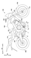
- FIG. 1 is a right side view of a saddle-type vehicle according to an embodiment of the present invention
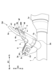
- FIG. 2 is an enlarged view of a portion of FIG. FIG.
- FIG. 3B Cross-sectional view of line AA in FIG. 3B.
- Cross-sectional view of line BB in FIG. 3B. 3 is a view of the exhaust gas sensor and its periphery taken in the direction of arrow D4 in FIG. 2 .
- FIG. 13 is a diagram showing another example of the arrangement of the exhaust gas sensor.
- FIG. 13 is a diagram showing another example of the arrangement of the exhaust gas sensor.
- 13A and 13B are diagrams showing other configuration examples of the front wall portion.
- 13A and 13B are diagrams showing other configuration examples of the front wall portion.
- FIG. 4 is a diagram showing a configuration example of a passing section.
- FIG. 4 is a diagram showing a configuration example of a passing section.
- FIG. 4 is a diagram showing a configuration example of a passing section.
- FIG. 4 is a diagram showing a configuration example of a passing section.
- FIG. 4 is a diagram showing a configuration example of a passing section.
- FIG. 4 is a diagram showing a configuration example of a passing section.
- FIG. 4 is a diagram showing a configuration example of a passing section.
- FIG. 4 is a diagram showing a configuration example of a passing section.
- FIG. 1 is a schematic diagram showing an overview of a saddle-ride type vehicle (hereinafter simply referred to as a vehicle) 100 according to an embodiment of the present invention, and Fig. 1 is a side view (right side view).
- the vehicle 100 is a motorcycle equipped with a front wheel FW and a rear wheel RW.
- the present invention is also applicable to saddle-ride type vehicles of a type other than that shown in Fig. 1.
- an arrow D1 indicates the front-rear direction of the vehicle 100, with Fr and Rr indicating the front and rear.
- An arrow D2 indicates the vehicle width direction, with R and L indicating the right and left.
- An arrow D3 indicates the up-down direction of the vehicle 100, with U and D indicating the up and down.
- the vehicle 100 has a body frame 101 that forms the skeleton of the vehicle.
- a front wheel steering unit 102 is supported at the front end of the body frame 101, and a swing arm 105 is supported at the rear end so that it can swing freely.
- the front wheel steering unit 102 includes a pair of left and right front forks 103 that support the front wheels FW via axles 112, and a steering handlebar 104 that is attached to the upper part of the front forks 103 via a top bridge (not shown).
- a front fender 111 is provided between the pair of front forks 103.
- the swing arm 105 has its front end supported by the body frame 101 so as to be able to swing freely, and its rear end supports the rear wheel RW.
- an internal combustion engine 106 and a transmission 107 are supported by the body frame 101.
- the internal combustion engine 106 is, for example, a water-cooled single-cylinder four-stroke engine.
- the output of the internal combustion engine 106 is transmitted to the rear wheel RW via the transmission 107 and a chain transmission mechanism (not shown).
- a fuel tank 109 is disposed above the internal combustion engine 106, and a seat 110 on which the rider sits is disposed behind the fuel tank 109.
- the exhaust system of the internal combustion engine 106 includes an exhaust passage 1 through which exhaust gas from the internal combustion engine 106 flows.
- the exhaust passage 1 includes an exhaust pipe 1b connected to an exhaust port of the internal combustion engine 106, a catalyst 1a, and a silencer 1c.
- the catalyst 1a is disposed midway through the exhaust pipe 1b, and the silencer 1c is disposed at the end of the exhaust pipe 1b.
- An exhaust gas sensor 2 is provided in the exhaust pipe 1b.
- the exhaust gas sensor 2 detects the components of the exhaust gas flowing through the exhaust pipe 1b. The detection results are reflected in the control of the internal combustion engine 106.
- the exhaust gas sensor 2 is, for example, an oxygen sensor that detects oxygen or an air-fuel ratio sensor (LAF sensor) that detects the air-fuel ratio.
- LAF sensor air-fuel ratio sensor
- a cover member 3 is provided adjacent to the exhaust gas sensor 2.
- the cover member 3 is a protective member that covers the exhaust gas sensor 2 and prevents pebbles and the like kicked up by the front wheels FW from colliding with the exhaust gas sensor 2 while the vehicle 100 is traveling. Please refer to FIG. 2 in addition to FIG. 1.
- FIG. 2 is an enlarged view of the area around the exhaust gas sensor 2 in FIG. 1.
- the exhaust pipe 1b is provided with a boss portion 2b to which the exhaust gas sensor 2 is attached.
- the exhaust gas sensor 2 has an axial outer shape extending in the D4 direction inclined from the D3 direction.
- the D4 direction can also be called the longitudinal or axial direction of the exhaust gas sensor 2.
- the boss portion 2b has an insertion hole in the D4 direction into which the tip (detection portion) of the exhaust gas sensor 2 is inserted, and a screw portion for fixing the exhaust gas sensor 2.
- a harness 2a is connected to the exhaust gas sensor 2, which transmits a signal indicating the detection result of the exhaust gas sensor 2 to a control unit (not shown) of the vehicle 100.
- the D4 direction is also the connection direction between the harness 2a and the exhaust gas sensor 2.
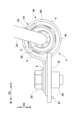
- FIG. 5 is a view of the exhaust gas sensor 2 as viewed in the direction D4 in FIG. 2.
- the cover member 3 is fixed to the bracket 2c by a fastener 2d.
- the fastener 2d is a bolt and a nut.
- the fastener 2d may also be a rivet.
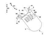
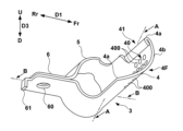
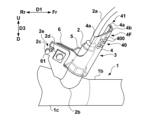
- Figures 3A and 3B are perspective views of the cover member 3.
- the cover member 3 integrally comprises a front wall portion 4, an annular portion 5, and an attachment portion 6.
- the front wall portion 4 is formed to extend upward from the annular portion 5, and the attachment portion 6 is formed to extend laterally from the annular portion 5.
- the cover member 3 is manufactured, for example, by processing a metal plate.
- the front wall portion 4 is disposed in front of the exhaust gas sensor 2 in the D1 direction.
- the front side of the exhaust gas sensor 2 is covered by the front wall portion 4, and the front wall portion 4 blocks pebbles and the like flying toward the exhaust gas sensor 2 from the front in the D1 direction, preventing them from colliding with the exhaust gas sensor 2.
- the front wall 4 is a wall that intersects with the D1 direction, and can be a factor in generating air resistance when the vehicle 100 is traveling due to the wind generated by the vehicle.
- the front wall 4 is formed with a passage 40 through which the wind passes, and this can reduce the air resistance caused by the wind. Therefore, the cover member 3 can protect the exhaust gas sensor 2 from flying stones and the like while traveling, while suppressing the air resistance caused by the wind.
- the passage portion 40 is composed of a plurality of circular through holes 400 that penetrate the front wall portion 4.
- the through holes 400 can be constructed with a relatively simple structure.
- the size of the through holes 400 can be designed as appropriate.
- the cover member 3 can adjust the balance between the performance of preventing pebbles and the like from colliding with the exhaust gas sensor 2 and the performance of reducing air resistance caused by the wind while driving.
- the passing section 40 of this embodiment is configured in a mesh-like manner by a plurality of through holes 400.
- the mesh may be regular or irregular.
- the plurality of through holes 400 are arranged in a regular manner.
- the portion through which the traveling wind passes can be dispersed.
- the size of each through hole 400 can be designed to be small. In other words, the blocking performance of pebbles entering the passing section 40 can be improved.
- the passing section 40 in a mesh-like manner by a plurality of through holes 400, the area of the passing section 40 can be increased while ensuring a certain rigidity, and it is possible to achieve both the effect of suppressing air resistance due to traveling wind and the performance of protecting the exhaust gas sensor 2.
- the passing section 40 by forming the passing section 40 with the mesh-like through holes 400, the weight of the front wall section 4 can be reduced.
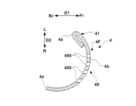
- Figure 4A is a cross-sectional view taken along line A-A in Figure 3B.
- the front wall portion 4 includes a left end portion 4a in the D2 direction, a right end portion 4a, and a central portion 4b between these two end portions 4a.
- the central portion 4b is located further forward in the D1 direction than the two end portions 4a, and forms the apex when viewed from the top of the front wall portion 4 shown in Figure 4A (viewed in the D4 direction).
- the central portion 4b is located at the frontmost portion of the front wall portion 4 in the D1 direction, it can also be called the tip portion.
- the center portion 4b of the front wall portion 4 in the D2 direction has a shape that bulges forward in the D1 direction. Because the traveling wind is separated to the left and right from the center portion 4b, the traveling wind that does not pass through the passing portion 40 is easily diverted to the rear side of the cover member 3, and the air resistance caused by the traveling wind can be further reduced.
- the front wall portion 4 of this embodiment has an arch shape, particularly with the central portion 4b curved in a direction that protrudes forward in the fore-and-aft direction of the vehicle 100. Because the front wall portion 4 has a curved shape, it is easier to deflect the wind from traveling rearward than if the front wall portion 4 was formed in a flat plate shape. This makes it possible to reduce the air resistance caused by the wind that the cover portion 3 receives. Furthermore, because the front wall portion 4 is curved and has a shell shape, its rigidity can be improved, and durability against impacts when hit by pebbles and the like can be increased.
- the front wall 4 has a bent portion 41 at the end 4a on the left side in the D2 direction.
- the bent portion 41 is formed by folding back the end edge of the material that constitutes the front wall 4.
- the bent portion 41 is formed along the range of the passing portion 40 in the D4 direction (see Figures 4A and 4B). In this way, by forming the bent portion 41 at the end 4a of the front wall 4, it is possible to prevent a decrease in the rigidity of the front wall 4a even if the rigidity of the front wall 4a decreases due to the provision of the passing portion 40 in the front wall 4.
- the bending direction of the bent portion 41 is from the front surface 4F side of the front wall portion 4 toward the exhaust gas sensor 2 side.
- the end portion 4a is bent toward the exhaust gas sensor 2 side to form the bent portion 41, and a structure in which the wind does not easily enter the bent portion 41 can be obtained compared to the case in which the end portion 4a is bent toward the front surface 4F side.
- the bent portion 41 can be structured so that it is not easily subjected to air resistance due to the wind.
- the harness 2a is configured to pass on the side of the bent portion 41, and when viewed in the D4 direction as shown in FIG. 5, the harness 2a and the bent portion 41 partially overlap. In this way, by providing the bent portion 41 at a position where the harness 2a passes on the side of the bent portion 41, even if the harness 2a and the front wall portion 4 come into contact with each other, it is possible to prevent the exterior of the harness 2a from being damaged by the bent portion 41 that is not sharp and hits the harness 2a.
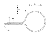
- Figure 4B is a cross-sectional view of line B-B in Figure 3B.
- the annular portion 5 is formed in a circular ring shape so as to surround the entire circumference of the exhaust gas sensor 2.
- the cover member 3 has the annular portion 5 that surrounds the exhaust gas sensor 2, thereby improving protection of the exhaust gas sensor 2.
- the impact is dispersed to the annular portion 5, preventing damage to the cover member 3.
- the mounting portion 6 is formed by overlapping flat plate portions of the material of the cover member 3, and a mounting hole 60 is formed through them in the plate thickness direction.
- the cover member 3 is fixed to the bracket 2c by passing a bolt constituting the fastener 2d through the mounting hole 60 and a hole in the bracket 2c (not shown) and fastening it with a nut.
- the mounting portion 6 also has an engagement portion 61 that engages with the recess 2e of the bracket 2c.
- the engagement portion 61 has the form of a protruding piece that is inserted into the valley of the recess 2e.
- the degree of freedom of the layout can be improved.
- the cover member 3 is directly attached to the boss portion 2b, it is necessary to consider the gap between the exhaust gas sensor 2 and the cover member 3 for attaching the exhaust gas sensor 2, and as a result, the annular portion 5 may become larger.
- the increase in size of the annular portion 5 may increase the air resistance caused by the wind during driving. Therefore, by attaching the cover member 3 to the boss portion 2b via the bracket 2c, the layout of the cover member 3 can be improved.
- the cover member 3 can be prevented from becoming unnecessarily large, and the air resistance caused by the wind during driving can be reduced.
- the engagement portion 61 engages with the recess 2e, forming a rotation stopper that rotates the cover member 3 around the fixing device 2d, preventing the cover member 3 from shifting out of position, and improving the protection performance of the exhaust gas sensor 2.
- the exhaust gas sensor 2 is provided in a straight portion of the exhaust pipe 1b downstream of the catalyst 1a, but the location of the exhaust gas sensor 2 is not limited to this.
- the location of the exhaust gas sensor 2 may be changed depending on the layout of the exhaust passage 1, the shape and number of the exhaust pipes 1b, etc.
- Figures 6A and 6B show examples of the location of the exhaust gas sensor 2.
- the exhaust gas sensor 2 is provided in the expanded diameter section 1d of the exhaust pipe 1b, which is connected to the upstream side of the catalyst 1a'.
- the cover member 3 is also arranged in a position adjacent to the expanded diameter section 1d.
- the exhaust gas is more likely to diffuse in the expanded diameter section 1d, and pressure loss is lower. Therefore, by providing the exhaust gas sensor 2 in the expanded diameter section 1d, it is possible to prevent the detection section at the tip of the exhaust gas sensor 2 from becoming a resistance to the exhaust gas flow inside the exhaust pipe 1b.
- the exhaust gas sensor 2 is provided in the expanded diameter section 1d upstream of the catalyst 1a', but if there is also an expanded diameter section downstream of the catalyst 1a', the exhaust gas sensor 2 may be provided in the expanded diameter section downstream of that.
- the exhaust gas sensor 2 is located in a portion of the upstream side of the silencer 1c.
- the cover member 3 is also located adjacent to the enlarged diameter portion 1d.
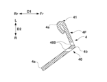
- FIG. 7A is a schematic diagram (cross-sectional view of the front wall portion 4) showing an example of this.
- the front wall portion 4 is bent at the center portion (top portion) 4b to form an L-shape or a mountain shape. In this way, even when the front wall portion 4 has a bent shape, it is easy to deflect the running wind to the rear, and the air resistance caused by the running wind can be reduced.
- a high rigidity portion 42 is formed at the end 4a of the front wall portion 4.
- the high rigidity portion 42 is a portion whose rigidity is improved by being thicker than the central portion 4b of the front wall portion 4.
- the high rigidity portion 42 is provided at the end portion 4a of the front wall portion 4, but the high rigidity portion 42 may be provided, for example, at the center portion 4b, or may be provided along the portion that forms the passing portion 40. In this way, by providing the high rigidity portion 42, it is possible to increase the degree of freedom in design, such as the size, shape, and arrangement of the through hole 400 that forms the passing portion 40.
- the passing portion 40 of the front wall portion 4 is configured with a plurality of through holes 400 formed in a mesh pattern.
- the passing portion 40 is not limited to this, and may be configured in the following shapes.
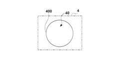
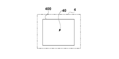
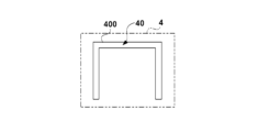
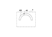
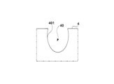
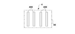
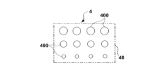
- Figures 8A to 8E are diagrams showing other configuration examples of the passing portion 40.
- FIG. 8A shows an example in which the passage portion 40 is configured with a single through hole 400. Even with only one through hole 400, it contributes to reducing air resistance.
- the shape of the through hole 400 is not limited to a circle.
- it may be a rectangle as in the example of FIG. 8B. It may also be a C-shape or a gate shape as in the example of FIG. 8C. It may also be an arc shape as in FIG. 8D.
- the passage 40 does not have to be a hole with a closed perimeter.
- Figure 8E shows an example in which the passage 40 is formed by a notch 401.
- the notch 401 has an open shape at the end of the front wall 4, and even with this shape, it contributes to reducing air resistance.
- Fig. 9A shows an example in which rectangular through holes 400 are arranged in a mesh pattern.
- Fig. 9B shows an example in which slit-shaped through holes 400 are arranged in the horizontal direction.
- Fig. 9C shows an example in which a plurality of through holes 400 of different sizes are arranged in a mesh pattern.
- Such configuration examples also contribute to reducing air resistance.
- the saddle-type vehicle (100) of the above embodiment is an exhaust passage (1) through which exhaust gas from an internal combustion engine (106) flows; an exhaust gas sensor (2) for detecting components of the exhaust gas flowing through the exhaust passage (1); a cover member (3) for covering the exhaust gas sensor (2);
- a saddle-type vehicle (100) comprising: the cover member (3) has a front wall portion (4) disposed in front of the exhaust gas sensor (2) in the front-rear direction of the saddle riding type vehicle (100), The front wall portion (4) is formed with a passage portion (40) through which the wind generated by running passes.
- the cover member can prevent pebbles and the like from colliding with the exhaust gas sensor when the saddle riding type vehicle is traveling.
- the passage portion since the passage portion is formed, air resistance caused by the traveling wind can be reduced. Therefore, the exhaust gas sensor can be protected from flying stones and the like while suppressing air resistance caused by the traveling wind.
- the passage portion (40) has at least one through hole (400) penetrating the front wall portion (4).
- the passage portion can be formed with a relatively simple structure.
- the cover member can achieve both the performance of preventing pebbles and the like from colliding with the exhaust gas sensor and the performance of reducing resistance due to wind while traveling.
- the front wall portion (4) has a top portion (4b) located between both end portions (4a) of the front wall portion (4) in the vehicle width direction and located forward of the both end portions (4a) in the front-rear direction. According to this embodiment, since the apex is located forward of both end portions of the front wall portion, it becomes easier to channel the traveling wind that does not pass through the passing portion to the rear of the front wall portion, thereby reducing air resistance caused by the traveling wind.
- the front wall portion (4) has a shape curved in a direction protruding forward in the front-rear direction. According to this embodiment, since the front wall portion has a curved shape, the wind generated by the vehicle can be easily deflected to the rear of the front wall portion, thereby reducing the air resistance caused by the wind. In addition, the rigidity of the front wall portion is improved compared to a flat plate-shaped configuration, and durability against impacts such as pebbles hitting the vehicle can be improved.
- the cover member (3) has an annular portion (5) that completely surrounds the exhaust gas sensor (2). According to this embodiment, the cover member can enhance the protective performance of the exhaust gas sensor, while dispersing the impact received when a pebble or the like hits the cover member, thereby preventing the cover member from being damaged.
- the passage portion (40) is configured in a mesh shape by a plurality of through holes (400) penetrating the front wall portion (4). According to this embodiment, since the passage portion is composed of the plurality of through holes, the air resistance can be dispersed among the individual through holes, and the size of each through hole can be designed to be small, thereby improving the blocking performance against pebbles and the like that may enter the passage portion.
- the front wall portion (4) has a high-rigidity portion (42) at an end portion (4a) in the vehicle width direction of the front wall portion (4) that has higher rigidity than a central portion (4b) in the vehicle width direction. According to this embodiment, even if the formation of the passage portion causes a partial decrease in rigidity of the front wall portion, the durability of the front wall portion can be increased against the impact of a collision with a pebble or the like.
- the front wall portion (4) has a bent portion (41) at an end portion (4a) of the front wall portion (4) in the vehicle width direction. According to this embodiment, even if the formation of the passage portion causes a partial decrease in rigidity of the front wall portion, the durability of the front wall portion can be increased against the impact of a collision with a pebble or the like.
- a harness (2a) connected to the exhaust gas sensor (2) passes through the front wall portion (4) on the side of the bent portion (41). According to this embodiment, since the end portion of the front wall portion is bent, even if the harness comes into contact with the front wall portion, the non-sharp bent portion comes into contact with the harness, thereby preventing the harness from being damaged.
- the bending direction of the bent portion (41) is a direction toward the exhaust gas sensor (2). According to this embodiment, by forming the bent portion by bending it toward the exhaust gas sensor, it is possible to reduce noise generated when the wind hits the bent portion. Also, by bending the bent portion toward the exhaust gas sensor, the bent portion is less susceptible to air resistance caused by the wind compared to a case where the bent portion is bent toward the opposite side.
- the saddle-type vehicle (100) of the above embodiment is a boss portion (2b) provided in the exhaust passage (1) and to which the exhaust gas sensor (2) is attached; and a bracket (2c) provided on the boss portion (2b) for holding the cover member (3).
- the cover member is attached via the bracket, which improves the layout flexibility of the cover member and prevents the cover member from becoming unnecessarily large.
- the cover member (3) of the above embodiment is A cover member (3) is attached to a saddle-type vehicle (100) including an exhaust passage (1) through which exhaust gas from an internal combustion engine (106) flows, and an exhaust gas sensor (2) that detects components of the exhaust gas flowing through the exhaust passage (1), the cover member (3) being attached to the exhaust gas sensor (2), a front wall portion (4) disposed in front of the exhaust gas sensor (2) in the fore-and-aft direction of the saddle riding type vehicle (100);
- the front wall portion (4) is formed with a passage portion (40) through which the wind generated by running passes.
- the cover member can prevent pebbles and the like from colliding with the exhaust gas sensor when the saddle-type vehicle is traveling.
- the passage portion since the passage portion is formed, air resistance caused by wind while the vehicle is traveling can be reduced. Therefore, the exhaust gas sensor can be protected from flying stones and the like while traveling, while suppressing air resistance caused by wind while the vehicle is traveling.
Landscapes
- Engineering & Computer Science (AREA)
- Mechanical Engineering (AREA)
- Chemical & Material Sciences (AREA)
- Combustion & Propulsion (AREA)
- General Engineering & Computer Science (AREA)
- Analytical Chemistry (AREA)
- Transportation (AREA)
- Exhaust Silencers (AREA)
Priority Applications (3)
| Application Number | Priority Date | Filing Date | Title |
|---|---|---|---|
| JP2025505268A JPWO2024185642A1 (cg-RX-API-DMAC7.html) | 2023-03-06 | 2024-02-29 | |
| EP24767012.8A EP4663525A4 (en) | 2023-03-06 | 2024-02-29 | SADDLE SEAT VEHICLE AND COVER ELEMENT |
| US19/318,589 US20260001613A1 (en) | 2023-03-06 | 2025-09-04 | Straddle type vehicle and cover member |
Applications Claiming Priority (2)
| Application Number | Priority Date | Filing Date | Title |
|---|---|---|---|
| JP2023-033863 | 2023-03-06 | ||
| JP2023033863 | 2023-03-06 |
Related Child Applications (1)
| Application Number | Title | Priority Date | Filing Date |
|---|---|---|---|
| US19/318,589 Continuation US20260001613A1 (en) | 2023-03-06 | 2025-09-04 | Straddle type vehicle and cover member |
Publications (1)
| Publication Number | Publication Date |
|---|---|
| WO2024185642A1 true WO2024185642A1 (ja) | 2024-09-12 |
Family
ID=92674958
Family Applications (1)
| Application Number | Title | Priority Date | Filing Date |
|---|---|---|---|
| PCT/JP2024/007534 Ceased WO2024185642A1 (ja) | 2023-03-06 | 2024-02-29 | 鞍乗型車両及びカバー部材 |
Country Status (4)
| Country | Link |
|---|---|
| US (1) | US20260001613A1 (cg-RX-API-DMAC7.html) |
| EP (1) | EP4663525A4 (cg-RX-API-DMAC7.html) |
| JP (1) | JPWO2024185642A1 (cg-RX-API-DMAC7.html) |
| WO (1) | WO2024185642A1 (cg-RX-API-DMAC7.html) |
Citations (8)
| Publication number | Priority date | Publication date | Assignee | Title |
|---|---|---|---|---|
| JPS546401U (cg-RX-API-DMAC7.html) * | 1977-06-17 | 1979-01-17 | ||
| JPS60161282A (ja) * | 1984-01-31 | 1985-08-22 | ヤマハ発動機株式会社 | 自動二輪車 |
| JPH05124561A (ja) * | 1991-09-11 | 1993-05-21 | Yamaha Motor Co Ltd | 自動二輪車の酸素センサー保護装置 |
| JPH08312343A (ja) * | 1995-05-11 | 1996-11-26 | Calsonic Corp | センサ付き触媒コンバータの遮熱装置 |
| JP2015068292A (ja) | 2013-09-30 | 2015-04-13 | 本田技研工業株式会社 | 自動二輪車における排気ガスセンサ保護構造 |
| JP2019142442A (ja) * | 2018-02-23 | 2019-08-29 | 本田技研工業株式会社 | 鞍乗り型車両の被冷却体保護構造 |
| WO2020035921A1 (ja) * | 2018-08-15 | 2020-02-20 | 本田技研工業株式会社 | 自動二輪車のo2センサ配置構造 |
| JP2020070794A (ja) * | 2018-11-02 | 2020-05-07 | 川崎重工業株式会社 | 鞍乗型車両 |
Family Cites Families (1)
| Publication number | Priority date | Publication date | Assignee | Title |
|---|---|---|---|---|
| US20080229821A1 (en) * | 2007-03-20 | 2008-09-25 | Reeder Kevin R | Sensor impact protection apparatus |
-
2024
- 2024-02-29 JP JP2025505268A patent/JPWO2024185642A1/ja active Pending
- 2024-02-29 WO PCT/JP2024/007534 patent/WO2024185642A1/ja not_active Ceased
- 2024-02-29 EP EP24767012.8A patent/EP4663525A4/en active Pending
-
2025
- 2025-09-04 US US19/318,589 patent/US20260001613A1/en active Pending
Patent Citations (8)
| Publication number | Priority date | Publication date | Assignee | Title |
|---|---|---|---|---|
| JPS546401U (cg-RX-API-DMAC7.html) * | 1977-06-17 | 1979-01-17 | ||
| JPS60161282A (ja) * | 1984-01-31 | 1985-08-22 | ヤマハ発動機株式会社 | 自動二輪車 |
| JPH05124561A (ja) * | 1991-09-11 | 1993-05-21 | Yamaha Motor Co Ltd | 自動二輪車の酸素センサー保護装置 |
| JPH08312343A (ja) * | 1995-05-11 | 1996-11-26 | Calsonic Corp | センサ付き触媒コンバータの遮熱装置 |
| JP2015068292A (ja) | 2013-09-30 | 2015-04-13 | 本田技研工業株式会社 | 自動二輪車における排気ガスセンサ保護構造 |
| JP2019142442A (ja) * | 2018-02-23 | 2019-08-29 | 本田技研工業株式会社 | 鞍乗り型車両の被冷却体保護構造 |
| WO2020035921A1 (ja) * | 2018-08-15 | 2020-02-20 | 本田技研工業株式会社 | 自動二輪車のo2センサ配置構造 |
| JP2020070794A (ja) * | 2018-11-02 | 2020-05-07 | 川崎重工業株式会社 | 鞍乗型車両 |
Non-Patent Citations (1)
| Title |
|---|
| See also references of EP4663525A1 |
Also Published As
| Publication number | Publication date |
|---|---|
| US20260001613A1 (en) | 2026-01-01 |
| EP4663525A1 (en) | 2025-12-17 |
| JPWO2024185642A1 (cg-RX-API-DMAC7.html) | 2024-09-12 |
| EP4663525A4 (en) | 2026-06-03 |
Similar Documents
| Publication | Publication Date | Title |
|---|---|---|
| US7374016B2 (en) | Muffler device | |
| EP2075179B1 (en) | Motorcycle | |
| EP2463187B1 (en) | Saddle riding type vehicle | |
| EP2832985B1 (en) | Air cleaner device for vehicle | |
| EP1900624B1 (en) | Motorcycle with exhaust pipe comprising an oxygen concentration sensor | |
| JP5460376B2 (ja) | 鞍乗型車両 | |
| JP2008024285A (ja) | 鞍乗型車両 | |
| EP3561252B1 (en) | Scooter | |
| JP6256255B2 (ja) | 自動二輪車のマフラー構造 | |
| WO2010113677A1 (ja) | 酸素濃度センサの取り付け構造 | |
| JP4911612B2 (ja) | 自動二輪車の排気装置 | |
| US20260001613A1 (en) | Straddle type vehicle and cover member | |
| WO2020035921A1 (ja) | 自動二輪車のo2センサ配置構造 | |
| EP4545764B1 (en) | Engine | |
| WO2017057340A1 (ja) | 鞍乗り型車両 | |
| WO2023189962A1 (ja) | 鞍乗型車両 | |
| JP2017149166A (ja) | 鞍乗型車両 | |
| JP4184736B2 (ja) | 自動二輪車のフロントフェンダ構造 | |
| JP6458398B2 (ja) | 自動二輪車のマフラー構造 | |
| CN109083754B (zh) | 排气装置 | |
| US20260002500A1 (en) | Cover structure | |
| JPWO2024185642A5 (cg-RX-API-DMAC7.html) | ||
| JP7059521B2 (ja) | 車両の排気装置 | |
| JP5480231B2 (ja) | 消音器の保護構造 | |
| EP2636584B1 (en) | Motorcycle |
Legal Events
| Date | Code | Title | Description |
|---|---|---|---|
| 121 | Ep: the epo has been informed by wipo that ep was designated in this application |
Ref document number: 24767012 Country of ref document: EP Kind code of ref document: A1 |
|
| DPE1 | Request for preliminary examination filed after expiration of 19th month from priority date (pct application filed from 20040101) | ||
| WWE | Wipo information: entry into national phase |
Ref document number: 2501005734 Country of ref document: TH |
|
| ENP | Entry into the national phase |
Ref document number: 2025505268 Country of ref document: JP Kind code of ref document: A |
|
| WWE | Wipo information: entry into national phase |
Ref document number: 2025505268 Country of ref document: JP |
|
| WWE | Wipo information: entry into national phase |
Ref document number: 202517085946 Country of ref document: IN |
|
| WWP | Wipo information: published in national office |
Ref document number: 202517085946 Country of ref document: IN |
|
| NENP | Non-entry into the national phase |
Ref country code: DE |
|
| WWP | Wipo information: published in national office |
Ref document number: 2024767012 Country of ref document: EP |