WO2024185486A1 - 金属板のプレス成形方法およびプレス装置 - Google Patents
金属板のプレス成形方法およびプレス装置 Download PDFInfo
- Publication number
- WO2024185486A1 WO2024185486A1 PCT/JP2024/005967 JP2024005967W WO2024185486A1 WO 2024185486 A1 WO2024185486 A1 WO 2024185486A1 JP 2024005967 W JP2024005967 W JP 2024005967W WO 2024185486 A1 WO2024185486 A1 WO 2024185486A1
- Authority
- WO
- WIPO (PCT)
- Prior art keywords
- die
- punch
- convex
- metal plate
- press
- Prior art date
- Legal status (The legal status is an assumption and is not a legal conclusion. Google has not performed a legal analysis and makes no representation as to the accuracy of the status listed.)
- Ceased
Links
Images
Classifications
-
- B—PERFORMING OPERATIONS; TRANSPORTING
- B21—MECHANICAL METAL-WORKING WITHOUT ESSENTIALLY REMOVING MATERIAL; PUNCHING METAL
- B21D—WORKING OR PROCESSING OF SHEET METAL OR METAL TUBES, RODS OR PROFILES WITHOUT ESSENTIALLY REMOVING MATERIAL; PUNCHING METAL
- B21D13/00—Corrugating sheet metal, rods or profiles; Bending sheet metal, rods or profiles into wave form
- B21D13/02—Corrugating sheet metal, rods or profiles; Bending sheet metal, rods or profiles into wave form by pressing
-
- B—PERFORMING OPERATIONS; TRANSPORTING
- B21—MECHANICAL METAL-WORKING WITHOUT ESSENTIALLY REMOVING MATERIAL; PUNCHING METAL
- B21D—WORKING OR PROCESSING OF SHEET METAL OR METAL TUBES, RODS OR PROFILES WITHOUT ESSENTIALLY REMOVING MATERIAL; PUNCHING METAL
- B21D22/00—Shaping without cutting, by stamping, spinning, or deep-drawing
- B21D22/02—Stamping using rigid devices or tools
-
- B—PERFORMING OPERATIONS; TRANSPORTING
- B21—MECHANICAL METAL-WORKING WITHOUT ESSENTIALLY REMOVING MATERIAL; PUNCHING METAL
- B21D—WORKING OR PROCESSING OF SHEET METAL OR METAL TUBES, RODS OR PROFILES WITHOUT ESSENTIALLY REMOVING MATERIAL; PUNCHING METAL
- B21D22/00—Shaping without cutting, by stamping, spinning, or deep-drawing
- B21D22/20—Deep-drawing
- B21D22/26—Deep-drawing for making peculiarly, e.g. irregularly, shaped articles
-
- B—PERFORMING OPERATIONS; TRANSPORTING
- B21—MECHANICAL METAL-WORKING WITHOUT ESSENTIALLY REMOVING MATERIAL; PUNCHING METAL
- B21D—WORKING OR PROCESSING OF SHEET METAL OR METAL TUBES, RODS OR PROFILES WITHOUT ESSENTIALLY REMOVING MATERIAL; PUNCHING METAL
- B21D24/00—Special deep-drawing arrangements in, or in connection with, presses
-
- H—ELECTRICITY
- H01—ELECTRIC ELEMENTS
- H01M—PROCESSES OR MEANS, e.g. BATTERIES, FOR THE DIRECT CONVERSION OF CHEMICAL ENERGY INTO ELECTRICAL ENERGY
- H01M8/00—Fuel cells; Manufacture thereof
- H01M8/02—Details
- H01M8/0202—Collectors; Separators, e.g. bipolar separators; Interconnectors
- H01M8/0204—Non-porous and characterised by the material
- H01M8/0206—Metals or alloys
Definitions
- the present invention relates to a method and a press device for press-forming metal sheets.
- Fuel cell separators are generally provided with uneven grooves that form gas flow paths for fuel gas and oxidant gas.
- a method for forming these uneven grooves is known in which a metal plate is press-molded using a press mold consisting of a die and a punch (see, for example, Patent Document 1).
- the plate material is pressed with the tip surface of the punch to form an overhang, and then the side wall of the overhang is sandwiched between the inclined surface of the die and the inclined surface of the punch and rolled to form a protrusion.
- the overhang is formed by overhang molding, and the side wall of the overhang is rolled to form a protrusion.
- the side wall of the protruding part is further rolled, so the side wall tends to become thin.
- cracks and deformations tend to occur between the protruding part and the thin side wall part. This makes it difficult to control the product thickness, and it is difficult to omit thickness inspection.
- the press forming method for metal plate includes a preforming process in which a convex curved surface is pressed against the pre-formed metal plate to form a protruding portion having an apex at the area pressed by the convex curved surface, and a shape forming process in which the outer areas on both sides of the pressed area in the protruding portion are pressed to flatten the apex, forming the flattened apex and a side wall portion connected to the apex and to which no pressing force is applied in the post-formed metal plate.
- the present invention makes it possible to improve the processing accuracy in press molding.
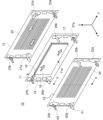
- FIG. 1 is an exploded perspective view showing a schematic configuration of a power generating cell of a fuel cell.
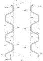
- FIG. 2 is a cross-sectional view taken along line AA of FIG.
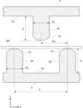
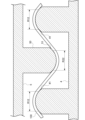
- FIG. 3 is a diagram showing a cross-sectional shape of a first press die used in the preforming step.
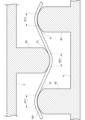
- FIG. 4 is a diagram showing a pressing state during the preforming step.
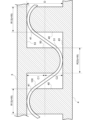
- FIG. 5 is a diagram showing another pressing state during the preforming step.
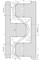
- FIG. 6 is a diagram showing the final pressing state of the preforming step.
- FIG. 7 is a diagram showing a cross-sectional shape of a second press die used in the shape forming step.
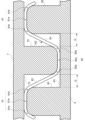
- FIG. 8 is a diagram showing the final pressing state of the shape forming process.
- FIG. 1 is an exploded perspective view showing a schematic configuration of a single power generation cell 10 used in a fuel cell stack.
- a fuel cell stack is formed by stacking a plurality of power generation cells. Of the three orthogonal axial directions in FIG. 1, the x-axis direction is the stacking direction of the power generation cells.
- the power generation cell 10 comprises a unitized electrode assembly (UEA) 11, and a first separator 12 and a second separator 13 arranged on either side of the unitized electrode assembly 11.
- arrow A1 (white) indicates the flow of oxidant gas
- arrow A2 hatchched indicates the flow of fuel gas.
- the first separator 12 and the second separator 13 are formed by pressing a thin metal plate.
- the thin metal plate that can be used include a steel plate, a stainless steel plate, an aluminum plate, a titanium plate, or a thin metal plate that has been subjected to a corrosion-resistant surface treatment.
- the integrated electrode structure 11 comprises a membrane electrode assembly (MEA) 11a and a frame member 14 joined to the periphery of the membrane electrode assembly 11a.
- the membrane electrode assembly 11a comprises an electrolyte membrane 15, an anode electrode 16 provided on one side of the electrolyte membrane 15, and a cathode electrode 17 provided on the other side of the electrolyte membrane 15.
- the frame member 14 is a rectangular ring-shaped frame member with a rectangular opening of approximately the same shape as the rectangular membrane electrode structure 11a.
- the anode electrode 16 and the cathode electrode 17 are arranged so that their outer peripheral edges sandwich the rectangular opening edge of the frame member 14, and are joined to the frame member 14 with an adhesive or the like.
- the rectangular opening edge of the frame member 14 is arranged so that it is sandwiched between the surface of the electrolyte membrane 15 on which the cathode electrode 17 is provided and the cathode electrode 17, and is joined to the electrolyte membrane 15 and the cathode electrode 17.
- the first separator 12 is provided with an oxidant gas outlet communication hole 20a, an oxidant gas inlet communication hole 20b, a fuel gas outlet communication hole 22a, and a fuel gas inlet communication hole 22b.
- the oxidant gas outlet communication hole 20a and the fuel gas inlet communication hole 22b are arranged side by side in the z direction at one end (negative side) of the first separator 12 in the y direction.
- the oxidant gas inlet communication hole 20b and the fuel gas outlet communication hole 22a are arranged side by side in the z direction at the other end (positive side) of the first separator 12 in the y direction.
- the frame member 14 is provided with an oxidant gas outlet communication hole 26a, an oxidant gas inlet communication hole 26b, a fuel gas outlet communication hole 27a, and a fuel gas inlet communication hole 27b.
- the oxidant gas outlet communication hole 26a and the fuel gas inlet communication hole 27b are arranged side by side in the z direction at one end (negative side) of the frame member 14 in the y direction.
- the oxidant gas inlet communication hole 26b and the fuel gas outlet communication hole 27a are arranged side by side in the z direction at the other end (positive side) of the frame member 14 in the y direction.
- the oxidant gas outlet communication hole 20a and the oxidant gas inlet communication hole 20b of the first separator 12 and the oxidant gas outlet communication hole 21a and the oxidant gas inlet communication hole 21b of the second separator 13 are arranged to face each other with the oxidant gas outlet communication hole 26a and the oxidant gas inlet communication hole 26b of the frame member 14 in between.
- the fuel gas outlet communication hole 22a and the fuel gas inlet communication hole 22b of the first separator 12 and the fuel gas outlet communication hole 23a and the fuel gas inlet communication hole 23b of the second separator 13 are arranged to face each other with the fuel gas outlet communication hole 27a and the fuel gas inlet communication hole 27b of the frame member 14 in between.
- first separator 12, the second separator 13 and the frame member 14 each have a cooling medium outlet communication hole and a cooling medium inlet communication hole between the communication holes 22b, 23, 27b and the communication holes 20a, 21a, 26a and between the communication holes 20b, 21b, 26b and the communication holes 22a, 23a, 27a.
- the first separator 12 and the second separator 13 are each formed by joining the outer peripheral edges of a pair of thin plates by welding or the like.
- the cooling medium flows inside the first separator 12 (between the pair of thin plates) and inside the second separator 13 along the Y direction.
- the surface of the first separator 12 facing the integrated electrode structure 11 has an uneven groove surface 24 extending in the y direction.
- the uneven groove surface 24 forms a fuel gas flow path between the first separator 12 and the integrated electrode structure 11 that communicates with the fuel gas inlet communication hole 22b and the fuel gas outlet communication hole 22a.
- the surface of the second separator 13 facing the integrated electrode structure 11 has an uneven groove surface 25 extending in the y direction.
- the uneven groove surface 25 forms an oxidizer gas flow path between the second separator 13 and the integrated electrode structure 11 that communicates with the oxidizer gas inlet communication hole 21b and the oxidizer gas outlet communication hole 21a.
- FIG. 2 is a portion of a cross-sectional view taken along line A-A of the power generating cell 10 shown in FIG. 1, and is a cross-sectional view of the concave-convex groove surfaces 24, 25 of the first separator 12 and the second separator 13.
- the separators 12, 13 are each formed by joining a pair of thin plates PL1, PL2, and FIG. 2 shows the thin plate PL1 on one side of the first separator 12 (the integrated electrode structure 11 side) and the thin plate PL2 on one side of the second separator 13 (the integrated electrode structure 11 side).
- the uneven grooved surfaces 24, 25 are formed by press molding.
- the uneven grooved surface 24 of the first separator 12 (thin plate PL1) has multiple convex portions 24a and concave portions 24b extending in the y direction, which are formed alternately in the z direction.
- a fuel gas flow path 30 is formed between the concave portions 24b and the opposing surface of the integrated electrode structure 11.
- the uneven grooved surface 25 of the second separator 13 (thin plate PL2) has multiple convex portions 25a and concave portions 25b extending in the y direction, which are formed alternately in the z direction.
- An oxidizer gas flow path 31 is formed between the concave portions 25b and the opposing surface of the integrated electrode structure 11.
- a cooling flow path is formed by the protrusion 24a, and the cooling medium flows along the cooling flow path.
- a cooling flow path is formed by the protrusion 25a, and the cooling medium flows along the cooling flow path.
- Thin plates PL1 and PL2 have the same shape, and thin plate PL1 becomes thin plate PL2 when it is inverted in the x-axis direction.
- Convex portions 24a, 25a and concave portions 24b, 25b have the same shape, and convex portions 24a, 25a become concave portions 24b, 25b when it is inverted in the x-axis direction.
- thin plates PL1 and PL2, and convex portions 24a, 25a and concave portions 24b, 25b do not have to have the same shape.
- the thickness of metal thin plates PL1, PL2 used for first and second separators 12, 13 is, for example, about 0.1 mm.
- the pitch (spacing in the z-direction) of concave portions 24b, 25b is, for example, about 1 mm, and the height of the concave and convex portions (width in the x-direction) is, for example, about 0.5 mm.
- the first separator 12 and the second separator 13 are formed by press-molding a thin metal plate.
- the press-molding method in this embodiment includes a pre-molding process and a shape-molding process.
- the first press die 3 is a diagram showing a cross-sectional shape of a first press die used in the preforming step.
- the first press die includes a die (hereinafter referred to as a die) 4 in which a sheet metal 100 (corresponding to sheets PL1 and PL2) that is a workpiece to be processed is set, and a die (hereinafter referred to as a punch) 5 that moves toward the die 4 to press the sheet metal 100.
- the die 4 and punch 5 each have a plurality of protrusions 40, 50 that press against the metal sheet 100.
- the protrusions 40 of the die 4 are formed so as to protrude from a flat surface (die flat surface) 43 facing the punch 5 toward the punch 5.
- the protrusions 50 of the punch 5 are formed so as to protrude from a flat surface (punch flat surface) 53 facing the die 4 toward the die 4.
- the convex portions 24a, 25a and the concave portions 24b, 25b of the separators 12, 13 have shapes that are inverted from each other in the x-axis direction ( Figure 2). Therefore, the convex portion 40 of the die 4 and the convex portion 50 of the punch 5 are configured to have the same shape (symmetrical in the x-axis direction).
- the multiple convex portions 40 are arranged in the z-axis direction at a predetermined pitch P.
- the multiple convex portions 50 are also arranged in the z-axis direction at the same pitch P as the convex portions 40.
- the convex portions 50 are arranged offset from the convex portions 40 in the z-axis direction by a pitch dimension of P/2.
- the height dimension of the convex portions 40, 50 is H
- the width dimension is W.
- the top of the convex portion 40 is formed by a convex curved surface 41 that is convex upward.
- the top of the convex portion 50 is formed by a convex curved surface 51 that is convex downward.
- the convex curved surfaces 41, 51 have a cross-sectional shape that forms a curved surface that is an arc.
- the convex portions 24a, 25a and the concave portions 24b, 25b of the first and second separators 12, 13 are symmetrical in shape, so the convex curved surface 41 of the convex portion 40 and the convex curved surface 51 of the convex portion 50 used to form them are curved surfaces of the same shape, with only the orientation of the surfaces being different.
- FIGS. 4 to 6 are diagrams for explaining the preforming step.
- Figures 4 and 5 are diagrams showing the pressing state during the preforming step.
- Figure 6 is a diagram showing the final pressing state in the preforming step.
- the metal sheet 100 is press-formed so that the material is stretched mainly in the region R21 where the convex curved surface 51 of the convex portion 50 of the punch 5 contacts, and in the region R11 where the convex curved surface 41 of the convex portion 40 of the die 4 contacts.
- the pressing force when a pressing force is applied to the portion where the convex curved surfaces 41, 51 contact, the pressing force mainly stretches the material in that portion, reducing the thickness.
- the portion of the metal sheet 100 where the convex portion 50 contacts deforms convex downward, and the portion where the convex portion 40 contacts deforms convex upward.
- FIG. 5 shows the state where the punch 5 has been further lowered from the state shown in FIG. 4.
- the contact area of the convex curved surfaces 41, 51 against the sheet metal 100 becomes larger than the pressing state in FIG. 4. That is, the contact area of the convex curved surfaces 41, 51 gradually expands as the punch 5 descends. Therefore, in FIG. 5, the regions R12, R22 where the convex curved surface 41 of the die 4 and the convex curved surface 51 of the punch 5 contact the sheet metal 100 are R12>R11 and R22>R21.
- a first protruding portion C1 is formed that is upwardly convex and has the pressing region (region R13) by the convex curved surface 41 of the convex portion 40 as its apex
- a second protruding portion C2 is formed that is downwardly convex and has the pressing region (region R23) by the convex curved surface 51 of the convex portion 50 as its apex.
- the first protruding portion C1 is located above the center in the height direction, and the second protruding portion C2 is located below the center in the height direction.
- the regions R13 and R23 to which the pressing force is applied are mainly deformed, and the thickness of these portions is slightly reduced.
- the height dimension may be set slightly larger, such as H0 + ⁇ H, so that a gap is created between flat portions 43, 53 and the top of the corrugated metal sheet 100.
- the die 6 and punch 7 each have a plurality of protrusions 60, 70 for pressing the metal sheet 100.
- the protrusions 60 of the die 6 are formed so as to protrude from the flat surface 63 facing the punch 7 toward the punch 7.
- the protrusions 70 of the punch 7 are formed so as to protrude from the flat surface 73 facing the die 6 toward the die 6.
- the protrusions 60 of the die 6 and the protrusions 70 of the punch 7 are configured to have the same shape (symmetrical in the x-axis direction).
- the multiple protrusions 60 are arranged in the z-axis direction at the same pitch P as in the case of die 4.
- the multiple protrusions 70 are also arranged in the z-axis direction at the same pitch P as the protrusions 60. Furthermore, the protrusions 70 are arranged at a pitch offset of P/2 in the z-axis direction relative to the protrusions 60.
- the height dimension of the protrusions 60 and 70 is H, and the width dimension is W1.
- the top of convex portion 60 is composed of a flat portion 61 and curved portions 62 provided on both ends of flat portion 61 in the z-axis direction.
- the top of convex portion 70 is composed of a flat portion 71 and curved portions 72 provided on both ends of flat portion 71 in the z-axis direction. Convex portions 60 and 70 have the same shape, and when convex portion 60 is inverted in the x-axis direction, it becomes convex portion 70.
- the corrugated sheet metal 100 is set on the die 6 as shown in FIG. 7.
- Region R13 in the corrugated sheet metal 100 is the region pressed by the convex portion 40 of the die 4 in the preliminary forming process.
- Region R23 is the region pressed by the convex portion 50 of the punch 5 in the preliminary forming process. In regions R13 and R23 pressed by the convex portions 40 and 50, the reduction in thickness of the sheet metal 100 due to forming is greater than in the unpressed regions.
- the width dimension W1 of the convex portion 60 of the die 6 used in the shape forming process is set so that the curved surface portions 62 formed on both ends of the flat portion 61 in the z-axis direction abut the area outside the region R13 of the sheet metal 100, i.e., the outer area (area where the reduction in thickness in the preforming process is relatively small). In other words, it is set so that W1 > W.
- the width dimension of the convex portion 70 of the punch 7 is set to W1 (> W), and the curved surface portions 72 on both ends of the flat portion 71 in the z-axis direction abut the area outside the region R23 of the sheet metal 100, i.e., the outer area.
- the punch 7 When the punch 7 is further lowered, the region R23 facing the flat portion 71 of the convex portion 70, i.e., the top of the second protrusion C2, is sandwiched between the flat portion 63 and the flat portion 71 of the die 6 and flattened. As with the case of region R23, the first protrusion C1 of the region R13 facing the flat portion 61 of the convex portion 60 is also sandwiched between the flat portion 61 and the flat portion 73 and flattened. Finally, the punch 7 is lowered to the position shown in Figure 8, and the shape forming process is completed. The metal sheet 100 is formed into the same uneven shape as the uneven groove surfaces 24, 25 shown in Figure 2.
- the thickness is reduced mainly in the area where the metal sheet 100 is pressed by the curved surface portions 62, 72. Since the metal sheet 100 is formed into a wave shape in the preforming process, the movement distance of the punch 7 from the start of forming in FIG. 7 to the end of forming in FIG. 8 is smaller than the movement distance of the punch 5 in the preforming process. In addition, since the area pressed by the curved surface portions 62, 72 is an area outside the areas R13, R23, the reduction in thickness in the preforming process is very small. Therefore, the reduction in thickness in the area pressed by the curved surface portions 62, 72 in all processes including the preforming process and the shape forming process can be kept small.
- the metal sheet 100 is sandwiched between the pressing areas of the curved surface portions 62, 62 or 72, 72, and the flow of the metal sheet 100 to the outside is prevented, so the change in the thickness of the metal sheet 100 is very small.
- the thickness of the metal sheet 100 is reduced mainly in the areas pressed by the curved surface portions 62, 72. Since the curved surface portions 62, 72 press the areas outside the areas R13, R23, in the shape forming process, the shape of the metal sheet 100 can be formed while suppressing the reduction in thickness of the areas R13, R23, which have been reduced in thickness by the preforming process.
- the finished molded product after the shape forming process has a top 81 formed to imitate the flat surface 61 and curved surface 62 (see FIG. 7) of the convex portion 60 of the die 6, a top 82 formed to imitate the flat surface 71 and curved surface 72 (see FIG. 7) of the convex portion 70 of the punch 7, and a side wall 83 connecting the tops 81 and 82.
- the flat portions 81a and 82a of the tops 81 and 82 are the flattened curved surface portions of the regions R13 and R23 formed in the preforming process, and the thickness hardly changes in the shape forming process.
- the R-shaped portions 81b and 82b at both ends of the tops 81 and 82 are formed in the shape forming process.
- each part of the tops 81, 82 of the finished product is formed in the preliminary forming process or the shape forming process. That is, the tops 81, 82 are the pressing areas in the press forming of this embodiment.
- the reduction in thickness due to forming is distributed over the entire area of the tops 81, 82, and localized reduction in thickness is suppressed.
- the reduction in thickness of the side wall portion 83 can be suppressed as much as possible.
- the part to which the pressing force is not applied is realized by forming a gap G (see FIG.
- the press molding method of this embodiment can suppress the reduction in thickness of the side wall portion 83 and minimize the overall reduction in thickness of the finished molded product. As a result, the processing accuracy in press molding can be improved, and thickness inspection can be omitted.
- the size of the regions R13, R23 to which the pressing force is applied in the preforming process is large as possible in order to distribute the reduction in wall thickness.
- the shape of the convex curved surfaces 41, 51 formed at the apex of the convex portions 40, 50 has been described as a convex curved surface whose cross-sectional shape is an arc, but it is possible to set it to various convex curved surface shapes.
- the cross-sectional shape is a sine wave shape (the shape of the apex region of the sine wave curved surface)
- it is highly effective in suppressing the reduction in thickness in regions R13, R23. Therefore, the shape of the convex curved surfaces 41, 51 may be a sine wave shape.
Landscapes
- Engineering & Computer Science (AREA)
- Mechanical Engineering (AREA)
- Life Sciences & Earth Sciences (AREA)
- Manufacturing & Machinery (AREA)
- Sustainable Development (AREA)
- Sustainable Energy (AREA)
- Chemical & Material Sciences (AREA)
- Chemical Kinetics & Catalysis (AREA)
- Electrochemistry (AREA)
- General Chemical & Material Sciences (AREA)
- Fuel Cell (AREA)
Priority Applications (2)
| Application Number | Priority Date | Filing Date | Title |
|---|---|---|---|
| JP2025505196A JPWO2024185486A1 (cg-RX-API-DMAC7.html) | 2023-03-03 | 2024-02-20 | |
| CN202480016236.6A CN120813440A (zh) | 2023-03-03 | 2024-02-20 | 金属板的冲压成型方法和冲压装置 |
Applications Claiming Priority (2)
| Application Number | Priority Date | Filing Date | Title |
|---|---|---|---|
| JP2023-032438 | 2023-03-03 | ||
| JP2023032438 | 2023-03-03 |
Publications (1)
| Publication Number | Publication Date |
|---|---|
| WO2024185486A1 true WO2024185486A1 (ja) | 2024-09-12 |
Family
ID=92674614
Family Applications (1)
| Application Number | Title | Priority Date | Filing Date |
|---|---|---|---|
| PCT/JP2024/005967 Ceased WO2024185486A1 (ja) | 2023-03-03 | 2024-02-20 | 金属板のプレス成形方法およびプレス装置 |
Country Status (3)
| Country | Link |
|---|---|
| JP (1) | JPWO2024185486A1 (cg-RX-API-DMAC7.html) |
| CN (1) | CN120813440A (cg-RX-API-DMAC7.html) |
| WO (1) | WO2024185486A1 (cg-RX-API-DMAC7.html) |
Citations (3)
| Publication number | Priority date | Publication date | Assignee | Title |
|---|---|---|---|---|
| JP2005243252A (ja) * | 2004-02-24 | 2005-09-08 | Honda Motor Co Ltd | 燃料電池用金属製セパレータの製造方法 |
| JP2019114515A (ja) * | 2017-12-26 | 2019-07-11 | トヨタ車体株式会社 | 燃料電池用セパレータの製造装置及び燃料電池用セパレータの製造方法 |
| JP2021159942A (ja) * | 2020-03-31 | 2021-10-11 | 本田技研工業株式会社 | 順送プレス方法、順送プレス装置、燃料電池用セパレータの製造方法、および燃料電池用セパレータの製造装置 |
-
2024
- 2024-02-20 WO PCT/JP2024/005967 patent/WO2024185486A1/ja not_active Ceased
- 2024-02-20 JP JP2025505196A patent/JPWO2024185486A1/ja active Pending
- 2024-02-20 CN CN202480016236.6A patent/CN120813440A/zh active Pending
Patent Citations (3)
| Publication number | Priority date | Publication date | Assignee | Title |
|---|---|---|---|---|
| JP2005243252A (ja) * | 2004-02-24 | 2005-09-08 | Honda Motor Co Ltd | 燃料電池用金属製セパレータの製造方法 |
| JP2019114515A (ja) * | 2017-12-26 | 2019-07-11 | トヨタ車体株式会社 | 燃料電池用セパレータの製造装置及び燃料電池用セパレータの製造方法 |
| JP2021159942A (ja) * | 2020-03-31 | 2021-10-11 | 本田技研工業株式会社 | 順送プレス方法、順送プレス装置、燃料電池用セパレータの製造方法、および燃料電池用セパレータの製造装置 |
Also Published As
| Publication number | Publication date |
|---|---|
| CN120813440A (zh) | 2025-10-17 |
| JPWO2024185486A1 (cg-RX-API-DMAC7.html) | 2024-09-12 |
Similar Documents
| Publication | Publication Date | Title |
|---|---|---|
| CN102082282B (zh) | 燃料电池用分隔体及其制造方法 | |
| US10926487B2 (en) | Press forming method and press forming apparatus for formed film of solid polymer electrolyte fuel cell | |
| JP6798291B2 (ja) | 金属板材の成形方法及び成形装置 | |
| JP2006228533A (ja) | 燃料電池用セパレータの成形方法及びセパレータ形状矯正装置 | |
| CN107968212B (zh) | 用于燃料电池的双极板及其制造方法 | |
| JP7017944B2 (ja) | 金属成形体の製造方法 | |
| KR102754570B1 (ko) | 금속판재를 이용한 모듈케이스의 제조방법 및 이와 같은 방법에 의해 제조된 모듈케이스 | |
| JP6642535B2 (ja) | 燃料電池用セパレータの製造方法 | |
| JP2007048616A (ja) | 燃料電池セパレータ、セパレータ製造装置及びセパレータ製造方法 | |
| JP4046550B2 (ja) | 反りが少ない固体高分子型燃料電池メタルセパレータ及びその製造方法 | |
| JP2019114515A (ja) | 燃料電池用セパレータの製造装置及び燃料電池用セパレータの製造方法 | |
| JP2002075401A (ja) | 固体高分子型燃料電池用セパレータ,その製造方法及び固体高分子型燃料電池 | |
| JP7778927B2 (ja) | バイポーラプレート、およびチャネル構造のエンボス加工方法 | |
| CN113451597B (zh) | 隔板以及隔板的制造方法 | |
| JP2012227132A (ja) | 金属セパレータの製造方法 | |
| JP4388389B2 (ja) | 燃料電池用金属製セパレータの製造方法 | |
| JP2019032952A (ja) | 燃料電池用セパレータの製造方法 | |
| CN120813440A (zh) | 金属板的冲压成型方法和冲压装置 | |
| US20230318004A1 (en) | Method for manufacturing fuel cell stack and method for manufacturing joint separator | |
| JP4291020B2 (ja) | 燃料電池用セパレータ及びそれの製造方法 | |
| JP7390936B2 (ja) | ガスケットの製造方法 | |
| JP2006221905A (ja) | 燃料電池用セパレータ及び燃料電池用セパレータの製造方法 | |
| CN1232363C (zh) | 一种控制拼焊板拉深焊缝移动的方法 | |
| JP4769570B2 (ja) | 金属薄板の成形方法 | |
| JP4765335B2 (ja) | 燃料電池用金属セパレータの成形方法および成形装置 |
Legal Events
| Date | Code | Title | Description |
|---|---|---|---|
| 121 | Ep: the epo has been informed by wipo that ep was designated in this application |
Ref document number: 24766857 Country of ref document: EP Kind code of ref document: A1 |
|
| ENP | Entry into the national phase |
Ref document number: 2025505196 Country of ref document: JP Kind code of ref document: A |
|
| WWE | Wipo information: entry into national phase |
Ref document number: 2025505196 Country of ref document: JP |
|
| WWE | Wipo information: entry into national phase |
Ref document number: 202480016236.6 Country of ref document: CN |
|
| NENP | Non-entry into the national phase |
Ref country code: DE |
|
| WWP | Wipo information: published in national office |
Ref document number: 202480016236.6 Country of ref document: CN |
|
| 122 | Ep: pct application non-entry in european phase |
Ref document number: 24766857 Country of ref document: EP Kind code of ref document: A1 |