WO2024185205A1 - 振動装置 - Google Patents
振動装置 Download PDFInfo
- Publication number
- WO2024185205A1 WO2024185205A1 PCT/JP2023/040072 JP2023040072W WO2024185205A1 WO 2024185205 A1 WO2024185205 A1 WO 2024185205A1 JP 2023040072 W JP2023040072 W JP 2023040072W WO 2024185205 A1 WO2024185205 A1 WO 2024185205A1
- Authority
- WO
- WIPO (PCT)
- Prior art keywords
- attenuator section
- vibration device
- attenuator
- optical axis
- section
- Prior art date
- Legal status (The legal status is an assumption and is not a legal conclusion. Google has not performed a legal analysis and makes no representation as to the accuracy of the status listed.)
- Ceased
Links
Images





Classifications
-
- B—PERFORMING OPERATIONS; TRANSPORTING
- B08—CLEANING
- B08B—CLEANING IN GENERAL; PREVENTION OF FOULING IN GENERAL
- B08B13/00—Accessories or details of general applicability for machines or apparatus for cleaning
-
- B—PERFORMING OPERATIONS; TRANSPORTING
- B06—GENERATING OR TRANSMITTING MECHANICAL VIBRATIONS IN GENERAL
- B06B—METHODS OR APPARATUS FOR GENERATING OR TRANSMITTING MECHANICAL VIBRATIONS OF INFRASONIC, SONIC, OR ULTRASONIC FREQUENCY, e.g. FOR PERFORMING MECHANICAL WORK IN GENERAL
- B06B1/00—Methods or apparatus for generating mechanical vibrations of infrasonic, sonic, or ultrasonic frequency
- B06B1/02—Methods or apparatus for generating mechanical vibrations of infrasonic, sonic, or ultrasonic frequency making use of electrical energy
- B06B1/06—Methods or apparatus for generating mechanical vibrations of infrasonic, sonic, or ultrasonic frequency making use of electrical energy operating with piezoelectric effect or with electrostriction
-
- B—PERFORMING OPERATIONS; TRANSPORTING
- B06—GENERATING OR TRANSMITTING MECHANICAL VIBRATIONS IN GENERAL
- B06B—METHODS OR APPARATUS FOR GENERATING OR TRANSMITTING MECHANICAL VIBRATIONS OF INFRASONIC, SONIC, OR ULTRASONIC FREQUENCY, e.g. FOR PERFORMING MECHANICAL WORK IN GENERAL
- B06B1/00—Methods or apparatus for generating mechanical vibrations of infrasonic, sonic, or ultrasonic frequency
- B06B1/02—Methods or apparatus for generating mechanical vibrations of infrasonic, sonic, or ultrasonic frequency making use of electrical energy
- B06B1/06—Methods or apparatus for generating mechanical vibrations of infrasonic, sonic, or ultrasonic frequency making use of electrical energy operating with piezoelectric effect or with electrostriction
- B06B1/0644—Methods or apparatus for generating mechanical vibrations of infrasonic, sonic, or ultrasonic frequency making use of electrical energy operating with piezoelectric effect or with electrostriction using a single piezoelectric element
- B06B1/0651—Methods or apparatus for generating mechanical vibrations of infrasonic, sonic, or ultrasonic frequency making use of electrical energy operating with piezoelectric effect or with electrostriction using a single piezoelectric element of circular shape
-
- B—PERFORMING OPERATIONS; TRANSPORTING
- B08—CLEANING
- B08B—CLEANING IN GENERAL; PREVENTION OF FOULING IN GENERAL
- B08B7/00—Cleaning by methods not provided for in a single other subclass or a single group in this subclass
- B08B7/02—Cleaning by methods not provided for in a single other subclass or a single group in this subclass by distortion, beating, or vibration of the surface to be cleaned
-
- G—PHYSICS
- G02—OPTICS
- G02B—OPTICAL ELEMENTS, SYSTEMS OR APPARATUS
- G02B27/00—Optical systems or apparatus not provided for by any of the groups G02B1/00 - G02B26/00, G02B30/00
- G02B27/0006—Optical systems or apparatus not provided for by any of the groups G02B1/00 - G02B26/00, G02B30/00 with means to keep optical surfaces clean, e.g. by preventing or removing dirt, stains, contamination, condensation
-
- G—PHYSICS
- G02—OPTICS
- G02B—OPTICAL ELEMENTS, SYSTEMS OR APPARATUS
- G02B7/00—Mountings, adjusting means, or light-tight connections, for optical elements
- G02B7/02—Mountings, adjusting means, or light-tight connections, for optical elements for lenses
-
- H—ELECTRICITY
- H04—ELECTRIC COMMUNICATION TECHNIQUE
- H04N—PICTORIAL COMMUNICATION, e.g. TELEVISION
- H04N23/00—Cameras or camera modules comprising electronic image sensors; Control thereof
- H04N23/50—Constructional details
- H04N23/52—Elements optimising image sensor operation, e.g. for electromagnetic interference [EMI] protection or temperature control by heat transfer or cooling elements
-
- H—ELECTRICITY
- H04—ELECTRIC COMMUNICATION TECHNIQUE
- H04N—PICTORIAL COMMUNICATION, e.g. TELEVISION
- H04N23/00—Cameras or camera modules comprising electronic image sensors; Control thereof
- H04N23/50—Constructional details
- H04N23/55—Optical parts specially adapted for electronic image sensors; Mounting thereof
Definitions
- the present invention relates to a vibration device.
- Patent document 1 discloses a vibration device equipped with a non-balance means for partially removing mass from or partially adding mass to at least one of the translucent body, the first cylindrical body, the second cylindrical body, the spring part, and the vibration body.
- the vibration device in Patent Document 1 has room for improvement in terms of removing foreign matter adhering to the translucent body.
- the present invention aims to provide a vibrating body that can remove foreign matter adhering to a transparent body.
- a vibration device comprises: An internal vibrator that amplifies vibration; a piezoelectric element connected to one end of the internal vibrator in a first direction and configured to generate vibrations; a transparent body connected to the other end of the internal vibrator in the first direction and having an optical axis extending along the first direction; an external vibrator including a first connection portion connected to the light-transmitting body and an attenuator portion extending from the first connection portion to the outside of the light-transmitting body along a second direction intersecting the first direction and attenuating vibration;
- the attenuator section is asymmetric with respect to the optical axis.
- the present invention provides a vibrating body that can remove foreign matter attached to a transparent body.
- FIG. 1 is a perspective view showing a vibration device according to an embodiment of the present invention
- FIG. 2 is a cross-sectional view taken along line II-II in FIG. 2 is a perspective view showing the vibration device of FIG. 1 as viewed from a different direction than that of FIG. 1
- 1 is a graph showing the relationship between impedance and frequency.
- FIG. 2 is a cross-sectional view showing a first modified example of the vibration device of FIG. 1 .
- FIG. 4 is a perspective view showing a second modified example of the vibration device of FIG. 1 .
- FIG. 4 is a cross-sectional view showing a third modified example of the vibration device of FIG. 1 .
- FIG. 13 is a cross-sectional view showing a fourth modified example of the vibration device of FIG. FIG.
- FIG. 13 is a perspective view showing a fifth modified example of the vibration device of FIG.
- FIG. 10 is a bottom view of the vibration device of FIG.
- FIG. 13 is a cross-sectional view showing a sixth modified example of the vibration device of FIG.
- FIG. 13 is a cross-sectional view showing a seventh modified example of the vibration device of FIG.
- FIG. 13 is a perspective view showing an example of wiring of the vibration device of FIG. 12 .
- FIG. 14 is a perspective view showing a first example of the wiring in FIG. 13 .
- FIG. 14 is a perspective view showing a second example of the wiring in FIG. 13 .
- the vibration device comprises: An internal vibrator that amplifies vibration; a piezoelectric element connected to one end of the internal vibrator in a first direction and configured to generate vibrations; a transparent body connected to the other end of the internal vibrator in the first direction and having an optical axis extending along the first direction; an external vibrator including a first connection portion connected to the light-transmitting body and an attenuator portion extending from the first connection portion to the outside of the light-transmitting body along a second direction intersecting the first direction and attenuating vibration;
- the attenuator section is asymmetric with respect to the optical axis.
- the attenuator section is non-axially symmetric, so that it is possible to impart a gradient to the vibration amplitude of the translucent body and reduce the bias of the stress applied to the internal vibrating body during vibration.
- a vibration device is the vibration device according to the first aspect, the attenuator section includes a first attenuator section and a second attenuator section that are positioned symmetrically with respect to the optical axis in a cross-sectional view along the optical axis, The dimension of the first attenuator section in the first direction is different from the dimension of the second attenuator section in the first direction.
- the second embodiment of the vibration device allows the appearance of the vibration device to be symmetrical.
- a third aspect of the present invention provides a vibration device according to the first aspect, the attenuator section includes a first attenuator section and a second attenuator section that are positioned symmetrically with respect to the optical axis in a cross-sectional view along the optical axis, The dimension of the first attenuator section in the second direction is different from the dimension of the second attenuator section in the second direction.
- the thickness which is the dimension in the first direction of the attenuator section, can be made constant, making it easier to process the external vibrator by cutting, pressing, etc.
- a fourth aspect of the present invention provides a vibration device according to the first aspect, the attenuator section includes a first attenuator section and a second attenuator section that are positioned symmetrically with respect to the optical axis in a cross-sectional view along the optical axis,
- the first attenuator section is made of a different material than the second attenuator section.
- the fourth embodiment of the vibration device allows the appearance of the vibration device to be symmetrical.
- a vibration device is the vibration device according to any one of the second to fourth aspects, When the amplitude of the vibration generated in the piezoelectric element is larger in the second attenuator section than in the first attenuator section, the first attenuator section is located vertically above the second attenuator section.
- the fifth aspect of the vibration device allows for more reliable removal of foreign matter.
- a sixth aspect of the present invention is a vibration device according to any one of the first to fifth aspects,
- the internal vibrator is positioned symmetrically with respect to the optical axis.
- the sixth aspect of the vibration device can more reliably reduce the bias of stress on the internal vibrating body during vibration, and can suppress unnecessary vibrations caused by non-axisymmetrical motion.
- a seventh aspect of the present invention is a vibration device according to any one of the first to sixth aspects,
- the piezoelectric elements are positioned symmetrically with respect to the optical axis.
- the seventh aspect of the vibration device can more reliably reduce the bias of stress acting on the internal vibrating body during vibration, and can also suppress unnecessary vibrations caused by non-axisymmetrical motion.
- the vibration device of an eighth aspect of the present invention is the vibration device of any one of the second to fourth aspects, When the amplitude of vibration generated in the piezoelectric element is larger in the second attenuator section than in the first attenuator section, wiring is connected to the piezoelectric element from a position closer to the first attenuator section than to the second attenuator section.
- the eighth aspect of the vibration device can prevent wiring breakage and noise caused by wiring vibration.
- a ninth aspect of the present invention provides a vibration device according to the eighth aspect,
- the wiring includes a shield portion capable of suppressing electromagnetic noise.
- the vibration device of the ninth aspect can improve the electromagnetic shielding effect for the imaging element at low cost without adding any additional shielding members.
- the tenth aspect of the vibration device of the present invention is the ninth aspect of the vibration device, in which the wiring includes at least two electrically independent conductive parts.
- a drive signal can be supplied to the piezoelectric element.
- the vibration device of an eleventh aspect of the present invention is the vibration device of the tenth aspect, the at least two conductive parts include a first conductive part connected to the piezoelectric element so as to be capable of transmitting a signal, and a second conductive part whose electric potential is fixed to a constant value; The second conductive portion has the same potential as the shield portion.
- an electric potential can be supplied to the piezoelectric element.
- a vibration device is the vibration device according to the eleventh aspect, an imaging element located on the optical axis inside the internal vibrator; the wiring includes a plurality of layers; The shield portion constitutes one of the plurality of layers and is located closer to the imaging element than the first conductive portion and the second conductive portion.
- the vibration device of the twelfth aspect can more reliably prevent noise from entering the imaging element circuit.
- a vibration device is the vibration device according to the eleventh or twelfth aspect, The first conductive portion and the second conductive portion are twisted.
- the vibration device of the thirteenth aspect can more reliably suppress electromagnetic noise.
- a vibration device is the vibration device according to any one of the first to thirteenth aspects,
- the attenuator unit is a second connection portion extending from the first connection portion to an outside of the light-transmitting body along the second direction;
- the optical axis includes a non-axisymmetric portion that is located closer to the light-transmitting body than the second connection portion in the first direction, is connected to the second connection portion, and has asymmetry with respect to the optical axis.
- a vibration device comprises: A vibrating body capable of amplifying vibrations; a piezoelectric element connected to one end of the vibrating body in a first direction and capable of generating vibrations; a transparent body connected to the other end of the vibrator in the first direction and having an optical axis extending along the first direction; an attenuator section located at an edge of the light-transmitting body in a second direction intersecting the first direction, connecting the vibrating body and the light-transmitting body, and configured to attenuate vibration; The attenuator section is asymmetric with respect to the optical axis.
- the vibration device of the 15th aspect can achieve both vibration containment and non-axial symmetry of the attenuator section.
- the vibration device 1 includes an internal vibrator 7, a piezoelectric element 9, a lens (an example of a light-transmitting body) 5, and an external vibrator 3.
- the piezoelectric element 9 is connected to one end of the internal vibrator 7 in a first direction (e.g., the Z direction).
- the lens 5 is connected to the other end of the internal vibrator 7 in the first direction Z.
- the lens 5 has an optical axis L extending along the first direction Z.
- the vibrations generated by the piezoelectric element 9 are transmitted to the lens 5 via the internal vibrator 7, causing the lens 5 to vibrate. This removes foreign matter such as water droplets or mud adhering to the lens 5.
- the internal vibrator 7 is configured to be able to amplify the vibrations generated by the piezoelectric element 9.
- the internal vibrator 7 is configured, for example, from a metal material or ceramics. Examples of metal materials that configure the internal vibrator 7 include stainless steel, aluminum, iron, titanium, and duralumin.
- the surface of the internal vibrator 7 may be subjected to a surface treatment such as oxidation or anodizing in order to improve the adhesion of the adhesive. For example, by making the surface of the internal vibrator 7 black by surface treatment, it is possible to prevent a decrease in optical performance due to diffuse reflection of light.
- the internal vibrator 7 is, for example, a cylindrical body, and is positioned symmetrically with respect to the optical axis L.
- the internal vibrator 7 includes a first portion 71 that contacts the lens 5, a second portion 72 to which the piezoelectric element 9 is attached, and a third portion 73 that connects the first portion 71 and the second portion 72.
- the first portion 71 and the second portion 72 have a cylindrical shape extending along the first direction Z.
- the second portion 72 is configured to vibrate together with the vibration of the piezoelectric element 9, and has a plate thickness (i.e., a dimension in the first direction Z) larger than the first portion 71 and the third portion 73.
- the third portion 73 has a cross-sectional shape that is approximately S-shaped.
- the third portion 73 is configured to support the first portion 71 and transmit the vibration of the second portion 72 to the first portion 71.
- the first portion 71, the second portion 72, and the third portion 73 may be formed integrally or separately.
- the maximum outer dimension of the third portion 73 i.e., the maximum dimension in a second direction (e.g., the X direction) intersecting the first direction Z
- the maximum outer dimension of the second portion 72 is larger than the maximum outer dimension of the third portion 73. This allows the vibration of the piezoelectric element 9 to be efficiently transmitted to the lens 5.
- the external vibrator 3 is configured to prevent the vibrations of the internal vibrator 7 from escaping to members other than the lens 5, and to efficiently transmit the vibrations to the lens 5.
- the external vibrator 3 is configured to cover the entire internal vibrator 7, protecting the internal vibrator 7 from the outside.
- the external vibrator 3 is made of, for example, a metal material such as stainless steel, aluminum, iron, titanium, or duralumin, or a resin.
- the external vibrator 3 for example, has a generally rectangular prism shape and includes a first connection portion 31, an attenuator portion 33, and a fixing portion 35.
- the first connection portion 31 extends from an end of the attenuator portion 33 in the second direction X that is closer to the internal vibrator 7 along the first direction Z and away from the piezoelectric element 9.
- the first connection portion 31 includes a plate-shaped portion 311 and a protrusion 312.
- the plate-shaped portion 311 extends from the attenuator portion 33 along the first direction Z.
- the protrusion 312 is located at an end of the plate-shaped portion 311 that is far from the attenuator portion 33 in the first direction Z.
- the protrusion 312 protrudes from the first connection portion 31 in the second direction X and in a direction approaching the lens 5.
- the edge of the lens 5 is sandwiched between the protrusion 312 and the first part 71 of the internal vibrator 7.
- the attenuator section 33 extends from the first connection section 31 outward from the lens 5 along the second direction X and is configured to dampen the vibrations generated by the piezoelectric element 9.
- the attenuator section 33 is thinner and less dense than the fixed section 35, and therefore has spring characteristics.
- the attenuator section 33 is asymmetric with respect to the optical axis L.
- the attenuator section 33 includes a first attenuator section 331 and a second attenuator section 332 that are positioned symmetrically with respect to the optical axis L in a cross-sectional view along the optical axis L.
- the dimension D1 (i.e., thickness dimension) of the first attenuator section 331 in the first direction Z is different from the dimension D2 of the second attenuator section 332 in the first direction Z.
- the vibration device 1 shown in Figures 1 to 3 is configured, as an example, so that the thickness dimension D1 of the first attenuator section 331 is larger than the thickness dimension D2 of the second attenuator section 332.
- the surface of the first attenuator section 331 facing the lens 5 in the first direction Z and the surface of the second attenuator section 332 facing the lens 5 in the first direction Z are located on approximately the same plane.
- the surface of the first attenuator section 331 facing the piezoelectric element 9 in the first direction Z is located closer to the piezoelectric element 9 than the surface of the second attenuator section 332 facing the piezoelectric element 9 in the first direction Z.
- the amplitude of the vibration generated by the piezoelectric element 9 is smaller in the first attenuator section 331 than in the second attenuator section 332.
- the vibration device 1 by positioning the vibration device 1 so that the first attenuator section 331 is positioned vertically above the second attenuator section 332, it is possible to promote the sliding of foreign matter from the lens 5.
- the wiring 100 is connected to the piezoelectric element 9 from a position closer to the first attenuator section 331 than to the second attenuator section 332, and a voltage is applied to the piezoelectric element 9 via the wiring 100.
- a voltage is applied to the piezoelectric element 9 via the wiring 100.
- the relationship between impedance and frequency of the vibration device 1 having non-axisymmetricity and the relationship between impedance and frequency of the vibration device having axisymmetricity are shown in FIG. 4.
- the relationship between impedance and frequency of the vibration device 1 is shown by a solid line
- the relationship between impedance and frequency of the vibration device having axisymmetricity is shown by a dotted line.
- the vibration device having axisymmetricity has the same configuration as the vibration device 1, except that the thickness dimension D1 of the first attenuator section 331 and the thickness dimension D2 of the second attenuator section 332 are the same. As shown in FIG.
- "Tilting the amplitude of the lens 5" means forming an area on the surface of the lens 5 where the lens 5 vibrates with a large amplitude and an area where the lens 5 vibrates with a small amplitude.
- the fixed portion 35 includes a node that suppresses vibration to less than 1/100th of the displacement of the lens 5, and is configured to be able to suppress vibrations propagated to components connected to the fixed portion 35 (e.g., the case that houses the image sensor and the lens module).
- the vibration of the fixed part 35 can be suppressed more effectively as the volume of the fixed part 35 increases, but when miniaturizing the vibration device 1, it is difficult to simply make the fixed part 35 larger.
- the fixed part 35 has a substantially rectangular outer shape. By configuring it in this way, the volume of the fixed part 35 can be increased without increasing the size of the vibration device 1. For example, the volume of a 25 mm x 25 mm cube is larger than that of a cylinder with a diameter of 25 mm.
- the external vibrator 3 is made of a material with a lower Young's modulus than the internal vibrator 7. By configuring it in this way, the attenuation of vibration by the attenuator section 33 can be increased.
- Lens 5 is made of, for example, glass.
- the upper surface of lens 5 has a convex shape, and as an example, the surface is coated with a water-repellent coating and an anti-reflection film (AR coating).
- the surface of lens 5 facing the optical imaging surface is made up of a flat portion 51 and a concave portion 52.
- Flat portion 51 is connected to the first part 71 of internal vibrator 7 by, for example, an adhesive.
- the piezoelectric element 9 has a piezoelectric body and electrodes, and is configured to generate vibration.
- the piezoelectric body is made of suitable piezoelectric ceramics such as barium titanate ( BaTiO3 ), lead zirconate titanate (PZT: PbTiO3.PbZrO3 ), lead titanate ( PbTiO3 ), lead metaniobate ( PbNb2O6 ), bismuth titanate ( Bi4Ti3O12 ), (K,Na) NbO3 , or suitable piezoelectric single crystals such as LiTaO3 and LiNbO3 .
- the electrodes are made of, for example, Ni , Ag , or Au.
- the piezoelectric element 9 has an annular shape when viewed along the first direction Z, and is positioned symmetrically with respect to the optical axis L.
- the piezoelectric element 9 is connected to the second part 72 of the internal vibrator 7 by, for example, an adhesive.
- the adhesive between the lens 5 and the internal vibrator 7, and the adhesive between the piezoelectric element 9 and the internal vibrator 7, are made of, for example, epoxy resin.
- the vibration device 1 can achieve the following effects:
- the vibration device 1 includes an internal vibrator 7 capable of amplifying vibrations, a piezoelectric element 9 connected to one end of the internal vibrator 7 in the first direction Z and capable of generating vibrations, a lens 5 connected to the other end of the internal vibrator 7 in the first direction Z and having an optical axis L extending along the first direction Z, and an external vibrator 3.
- the external vibrator 3 includes a first connection portion 31 connected to the lens, and an attenuator portion 33 that extends from the first connection portion 31 to the outside of the lens 5 along the second direction X and attenuates vibrations.
- the attenuator portion 33 is asymmetrical with respect to the optical axis L. This configuration can impart a tilt to the amplitude of the lens 5 during vibration, and can reduce bias in the stress applied to the internal vibrator 7 during vibration.
- the attenuator section 33 has a first attenuator section 331 and a second attenuator section 332 that are positioned symmetrically with respect to the optical axis L in a cross-sectional view along the optical axis.
- the dimension D1 in the first direction Z of the first attenuator section 331 is different from the dimension D2 in the first direction Z of the second attenuator section 332.
- the internal vibrator 7 is positioned symmetrically with respect to the optical axis L. This configuration can more reliably reduce the bias of the stress acting on the internal vibrator during vibration, and can also suppress unnecessary vibrations caused by non-axisymmetry.
- the piezoelectric element 9 is positioned symmetrically with respect to the optical axis L. This configuration can more reliably reduce the bias of the stress applied to the internal vibrator 7 during vibration, and can also suppress unnecessary vibrations caused by non-axial symmetry.
- the vibration device 1 can be configured as follows:
- the non-axial symmetry of the attenuator section 33 is not limited to the case where the thickness dimension D1 of the first attenuator section 331 and the thickness dimension D2 of the second attenuator section 332 are different.
- the attenuator section 33 may be provided with non-axial symmetry by the configurations shown in Figures 5 to 11.
- the dimension W1 in the second direction X of the first attenuator section 331 is different from the dimension W2 in the second direction X of the second attenuator section 332.
- the dimension W2 of the second attenuator section 332 is larger than the dimension W1 of the first attenuator section 331.
- the first attenuator section 331 is made of a material that is different from the material that is used for the second attenuator section 332.
- the first attenuator section 331 is made of a material that has a larger Young's modulus than the second attenuator section 332.
- the appearance of the vibration device 1 can be made symmetrical.
- the amplitude of the vibration generated by the piezoelectric element 9 is smaller in the first attenuator section 331 than in the second attenuator section 332.
- the first attenuator section 331 and the second attenuator section 332 may not necessarily have different Young's modulus, and may have different densities or mechanical Q values, for example.
- the attenuator section 33 includes a second connection section 41 and a non-axisymmetric section 42.
- the second connection section 41 extends from the first connection section 31 outwardly of the lens 5 along the second direction X, and is formed integrally with the first connection section 31 and the fixing section 35.
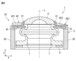
- the non-axisymmetric section 42 is non-axisymmetric with respect to the optical axis L, and is located closer to the lens 5 in the first direction Z than the second connection section 41.
- the non-axisymmetric section 42 is, for example, formed of a cover member that covers the outer surface of the second connection section 41, and the non-axisymmetric section 42 connected to the second connection section via an adhesive or the like has a first attenuator section 421 and a second attenuator section 422 that are located symmetrically with respect to the optical axis L in a cross-sectional view along the optical axis L.
- the first attenuator section 421 contacts and pressurizes the second connection section 41, but the second attenuator section 422 does not contact the second connection section 41, and a gap 43 is formed between the second attenuator section 422 and the second connection section 41.
- the amount of pressure applied by the non-axisymmetric section 42 to the second connection section 41 is asymmetric with respect to the optical axis L.
- both the first attenuator section 421 and the second attenuator section 422 are in contact with the second connection section 41, but the thickness dimensions of the first attenuator section 421 and the second attenuator section 422 are different.
- the first attenuator section 421 has a substantially rectangular cross section
- the second attenuator section 422 has an inclined surface 423 that inclines so as to approach the second connection section 41 in the first direction Z as it moves away from the first connection section 31 along the second direction X.
- the non-axisymmetric property of the non-axisymmetric portion 42 is not limited to the examples shown in Figs. 7 and 8.
- the non-axisymmetric property of the non-axisymmetric portion 42 may be imparted by making the thicknesses of the first attenuator portion 421 and the second attenuator portion 422 different when both the first attenuator portion 421 and the second attenuator portion 422 have a substantially rectangular cross section.
- the non-axisymmetric property of the non-axisymmetric portion 42 may be imparted by making the materials of the first attenuator portion 421 and the second attenuator portion 422 different.
- the vibration device 1 shown in Figures 9 and 10 When viewed along the first direction Z, the vibration device 1 shown in Figures 9 and 10 has an inner surface of the external vibrator 3 that is approximately circular, and the second attenuator section 332 that is approximately circular.
- the center of the inner surface of the external vibrator 3 approximately coincides with the optical axis L.
- the center point C of the second attenuator section 332 does not coincide with the optical axis L and is located at a position different from the optical axis L.
- the second attenuator section 332 can be processed, for example, by cutting using a lathe. In other words, an asymmetric attenuator section 33 can be formed even by general processing means such as a lathe.
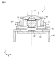
- the vibration device 1 shown in FIG. 11 includes a piezoelectric element 9 capable of generating vibrations, a vibrating body 10, a lens 5, and an attenuator section 60 configured to attenuate the vibrations.
- the vibrating body 10 is configured to be able to amplify the vibrations.
- the piezoelectric element 9 is connected to one end of the vibrating body 10 in the first direction Z.
- the lens is connected to the other end of the vibrating body 10 in the first direction Z.
- the vibrating body 10 is bonded to the piezoelectric element 9 and the lens 5, for example, by an adhesive.
- the vibration device 1 shown in FIG. 11 includes a housing 80 and an imaging section 82.
- the housing 80 is cylindrical with an open end 81, and includes a substrate 83 located at the open end 81.
- the imaging section 82 includes an imaging element and is fixed to the substrate 83.
- a vibration structure 20 including a lens 5, a vibrating body 10, and an inner layer lens 11 is fixed to the open end 81 of the housing 80.
- the vibration structure 20 includes a fixing section 21 and an inner layer lens barrel 22.
- the fixing section 21 fixes the lens 5 and the vibrating body 10 to the inner layer lens barrel 22.
- the inner layer lens barrel 22 is configured to hold the inner layer lens 11, and is fixed to the open end 81 of the housing 80.
- the attenuator section 60 is located at the edge of the lens 5 in the second direction X, and connects the vibrating body 10 and the lens 5.
- the attenuator section 60 is, for example, composed of a separate member from the vibrating body 10, and is screwed to the vibrating body 10. This holds the edge of the lens 5 between the attenuator section 60 and the vibrating body 10, preventing the lens 5 from falling off.
- the vibrating body 10, which is closer to the node of vibration than the lens 5 can be fixed by the fixing section 21, so that it is possible to achieve both vibration containment and non-axial symmetry of the attenuator section 60.
- the non-axial symmetry of the attenuator section 33 may be imparted by combining any two or more of the configurations shown in Figures 1 to 11.
- the first attenuator section 331, 421 and the second attenuator section 332, 422 may be configured to be positioned asymmetrically with respect to the optical axis L in at least one cross-sectional view along the optical axis L.
- the first attenuator section 331, 421 may or may not be located vertically above the second attenuator section 332, 422.
- the internal vibrator 7 and the piezoelectric element 9 may or may not be positioned symmetrically with respect to the optical axis L.
- the wiring 100 may or may not be connected to the piezoelectric element 9 from a position closer to the first attenuator section 331, 421 than to the second attenuator section 332, 422.
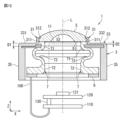
- the wiring 100 is connected to the piezoelectric element 9 and the drive circuit 110.
- the drive circuit 110 is connected to the image sensor board 120 by an inter-board connector 130.
- the image sensor board 120 has an image sensor 121 mounted thereon.
- the image sensor 121 is located on the optical axis L inside the internal vibrating body 7.
- the inner lens 11 is located between the lens 5 and the image sensor 121 in the first direction Z.
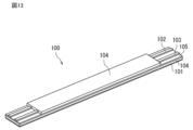
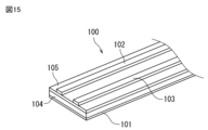
- the wiring 100 includes a shielding section 101 and two electrically independent conductive sections. This wiring 100 can improve the electromagnetic shielding effect for the imaging element 121 at low cost without adding any additional shielding materials.
- the two conductive sections can supply a drive signal to the piezoelectric element 9.
- the wiring 100 is a flexible substrate including multiple layers, with the shielding section 101 and the two conductive sections each constituting one of the multiple layers.
- the wiring 100 is laminated in the order of the shielding section 101, the protective layer 104, the base film 105, the two conductive sections, and the protective layer 104.
- the protective layer 104 and the base film 105 are formed, for example, from polyimide (PI) or a PET film.
- the shield section 101 is configured to be capable of suppressing electromagnetic noise. By configuring the shield section 101 to be located closest to the image sensor 121 among the multiple layers, it is possible to more reliably suppress the intrusion of electromagnetic noise into the image sensor 121 circuitry.
- the shield section 101 is formed, for example, from copper foil, permalloy, or iron.
- the two conductive parts (hereinafter referred to as the first conductive part 102 and the second conductive part 103) are electrically independent from each other (in other words, they are not electrically short-circuited).
- the first conductive part 102 and the second conductive part 103 are formed, for example, from copper foil, and are located between the base film 105 and the protective layer 104.
- the first conductive part 102 is connected to the piezoelectric element 9 so that a signal can be transmitted.
- the second conductive part 103 has the same potential as the shield part 101.
- the potential of the second conductive part 103 is fixed to a constant value including ground. This allows a potential to be supplied to the piezoelectric element 9.
- the first conductive part 102 and the second conductive part 103 are twisted in the part covered with the protective layer 104.
- the electromotive force due to the magnetic field can be canceled, and electromagnetic noise can be more reliably suppressed.
- the shield part 101 in the wiring 100, the electromagnetic shielding effect for the image sensor 121 can be improved at low cost without adding any other shielding material.
- through holes 104 that penetrate the shield part 101 are provided on both sides of the part where the first conductive part 102 and the second conductive part 103 of the shield part 101 are twisted.
- the portion of the wiring 100 in FIG. 14 that is not covered by the protective layer 104 extends along the direction in which the wiring 100 extends, with a predetermined gap between them in the width direction perpendicular to the direction in which the wiring 100 extends.
- configuration other than the shield portion 101, the first conductive portion 102, and the second conductive portion 103 is omitted.
- the first conductive portion 102 and the second conductive portion 103 are not twisted in the portion covered by the protective layer 104.
- the first conductive portion 102 and the second conductive portion 103 extend in the direction in which the wiring 100 extends, with a predetermined gap between them in the width direction, even in the portion covered by the protective layer 104.
- one electrode layer constituting the first conductive portion 102 and the second conductive portion 103 is reduced compared to the wiring 100 of FIG. 14, so that the electromagnetic shielding effect for the imaging element 121 can be improved at a lower cost.
- Vibration device External vibrating body 5
- Lens 7 Internal vibrating body 9
- Piezoelectric element 10 Vibrating body 11
- Inner lens 21 Fixing portion 22
- Inner lens barrel 31 First connecting portion 33
- Attenuator portion 35
- Fixing portion 42
- Non-axisymmetric portion 43
- Gap 51
- Planar portion 52 Recess 60
- Attenuator portion 71
- First portion 72
- Second portion 73
- Substrate 100 Wiring 311 Plate-shaped portion 312 Protruding portion 331, 421 First attenuator portion 332, 422 Second attenuator portion 423 Inclined surface
Landscapes
- Physics & Mathematics (AREA)
- Engineering & Computer Science (AREA)
- General Physics & Mathematics (AREA)
- Optics & Photonics (AREA)
- Mechanical Engineering (AREA)
- Multimedia (AREA)
- Signal Processing (AREA)
- Electromagnetism (AREA)
- Mechanical Light Control Or Optical Switches (AREA)
- Measurement Of Mechanical Vibrations Or Ultrasonic Waves (AREA)
- General Electrical Machinery Utilizing Piezoelectricity, Electrostriction Or Magnetostriction (AREA)
Priority Applications (4)
| Application Number | Priority Date | Filing Date | Title |
|---|---|---|---|
| JP2025505064A JPWO2024185205A1 (https=) | 2023-03-03 | 2023-11-07 | |
| DE112023005495.9T DE112023005495T5 (de) | 2023-03-03 | 2023-11-07 | Schwingungsvorrichtung |
| CN202380094911.2A CN120813879A (zh) | 2023-03-03 | 2023-11-07 | 振动装置 |
| US19/289,376 US20250362495A1 (en) | 2023-03-03 | 2025-08-04 | Vibration device |
Applications Claiming Priority (2)
| Application Number | Priority Date | Filing Date | Title |
|---|---|---|---|
| JP2023032840 | 2023-03-03 | ||
| JP2023-032840 | 2023-03-03 |
Related Child Applications (1)
| Application Number | Title | Priority Date | Filing Date |
|---|---|---|---|
| US19/289,376 Continuation US20250362495A1 (en) | 2023-03-03 | 2025-08-04 | Vibration device |
Publications (1)
| Publication Number | Publication Date |
|---|---|
| WO2024185205A1 true WO2024185205A1 (ja) | 2024-09-12 |
Family
ID=92674640
Family Applications (1)
| Application Number | Title | Priority Date | Filing Date |
|---|---|---|---|
| PCT/JP2023/040072 Ceased WO2024185205A1 (ja) | 2023-03-03 | 2023-11-07 | 振動装置 |
Country Status (5)
| Country | Link |
|---|---|
| US (1) | US20250362495A1 (https=) |
| JP (1) | JPWO2024185205A1 (https=) |
| CN (1) | CN120813879A (https=) |
| DE (1) | DE112023005495T5 (https=) |
| WO (1) | WO2024185205A1 (https=) |
Citations (2)
| Publication number | Priority date | Publication date | Assignee | Title |
|---|---|---|---|---|
| WO2021100232A1 (ja) * | 2019-11-22 | 2021-05-27 | 株式会社村田製作所 | 振動装置、および振動装置を備える撮像ユニット |
| WO2022091073A1 (ja) * | 2020-10-30 | 2022-05-05 | 株式会社村田製作所 | 洗浄装置、洗浄装置を備える撮像ユニット、および洗浄方法 |
-
2023
- 2023-11-07 WO PCT/JP2023/040072 patent/WO2024185205A1/ja not_active Ceased
- 2023-11-07 JP JP2025505064A patent/JPWO2024185205A1/ja active Pending
- 2023-11-07 DE DE112023005495.9T patent/DE112023005495T5/de active Pending
- 2023-11-07 CN CN202380094911.2A patent/CN120813879A/zh active Pending
-
2025
- 2025-08-04 US US19/289,376 patent/US20250362495A1/en active Pending
Patent Citations (2)
| Publication number | Priority date | Publication date | Assignee | Title |
|---|---|---|---|---|
| WO2021100232A1 (ja) * | 2019-11-22 | 2021-05-27 | 株式会社村田製作所 | 振動装置、および振動装置を備える撮像ユニット |
| WO2022091073A1 (ja) * | 2020-10-30 | 2022-05-05 | 株式会社村田製作所 | 洗浄装置、洗浄装置を備える撮像ユニット、および洗浄方法 |
Also Published As
| Publication number | Publication date |
|---|---|
| JPWO2024185205A1 (https=) | 2024-09-12 |
| CN120813879A (zh) | 2025-10-17 |
| DE112023005495T5 (de) | 2025-11-13 |
| US20250362495A1 (en) | 2025-11-27 |
Similar Documents
| Publication | Publication Date | Title |
|---|---|---|
| JP7816380B2 (ja) | 振動装置及び撮像装置 | |
| US5577507A (en) | Compound lens for ultrasound transducer probe | |
| EP3731014A1 (en) | Vibration device and optical detection device | |
| WO2005067346A1 (ja) | 圧電アクチュエータ | |
| CN103858442A (zh) | 超声波发生装置 | |
| CN105144749A (zh) | 超声波产生装置 | |
| WO2024185205A1 (ja) | 振動装置 | |
| JPWO2024185205A5 (https=) | ||
| CN118786687A (zh) | 超声波换能器 | |
| KR20120059196A (ko) | 초음파 센서 | |
| CN104718768A (zh) | 电声换能器及其制造方法和使用电声换能器的电子设备 | |
| WO2022107566A1 (ja) | 振動装置 | |
| WO2025052705A1 (ja) | 振動装置 | |
| CN118355323A (zh) | 光学模块和光学装置 | |
| JP7708330B1 (ja) | 超音波トランスデューサおよびこれを備えるパラメトリックスピーカ | |
| JP7772233B2 (ja) | 超音波トランスデューサおよびこれを備えるパラメトリックスピーカ | |
| JPS59218098A (ja) | 超音波セラミツクマイクロホン | |
| JPH0746694A (ja) | 超音波トランスデューサ | |
| JP7779326B2 (ja) | 振動装置および撮像装置 | |
| CN121970363A (zh) | 振动装置和内部振动体 | |
| JP7550066B2 (ja) | 振動デバイス | |
| WO2025115256A1 (ja) | 超音波トランスデューサおよびこれを備えるパラメトリックスピーカ | |
| JP7710845B2 (ja) | 振動デバイス及び圧電振動子 | |
| CN119677598A (zh) | 供电构件和振动装置 | |
| JP2023116037A (ja) | 圧電トランスデューサ |
Legal Events
| Date | Code | Title | Description |
|---|---|---|---|
| 121 | Ep: the epo has been informed by wipo that ep was designated in this application |
Ref document number: 23926413 Country of ref document: EP Kind code of ref document: A1 |
|
| ENP | Entry into the national phase |
Ref document number: 2025505064 Country of ref document: JP Kind code of ref document: A |
|
| WWE | Wipo information: entry into national phase |
Ref document number: 2025505064 Country of ref document: JP |
|
| WWE | Wipo information: entry into national phase |
Ref document number: 202380094911.2 Country of ref document: CN |
|
| WWE | Wipo information: entry into national phase |
Ref document number: 112023005495 Country of ref document: DE |
|
| WWP | Wipo information: published in national office |
Ref document number: 202380094911.2 Country of ref document: CN |
|
| WWP | Wipo information: published in national office |
Ref document number: 112023005495 Country of ref document: DE |
|
| 122 | Ep: pct application non-entry in european phase |
Ref document number: 23926413 Country of ref document: EP Kind code of ref document: A1 |