WO2024181501A1 - 保護装置及び保護方法 - Google Patents
保護装置及び保護方法 Download PDFInfo
- Publication number
- WO2024181501A1 WO2024181501A1 PCT/JP2024/007317 JP2024007317W WO2024181501A1 WO 2024181501 A1 WO2024181501 A1 WO 2024181501A1 JP 2024007317 W JP2024007317 W JP 2024007317W WO 2024181501 A1 WO2024181501 A1 WO 2024181501A1
- Authority
- WO
- WIPO (PCT)
- Prior art keywords
- airbag
- user
- fluid
- protection device
- head
- Prior art date
- Legal status (The legal status is an assumption and is not a legal conclusion. Google has not performed a legal analysis and makes no representation as to the accuracy of the status listed.)
- Ceased
Links
Images








Classifications
-
- A—HUMAN NECESSITIES
- A42—HEADWEAR
- A42B—HATS; HEAD COVERINGS
- A42B3/00—Helmets; Helmet covers ; Other protective head coverings
- A42B3/04—Parts, details or accessories of helmets
- A42B3/10—Linings
- A42B3/12—Cushioning devices
- A42B3/121—Cushioning devices with at least one layer or pad containing a fluid
- A42B3/122—Cushioning devices with at least one layer or pad containing a fluid inflatable
-
- A—HUMAN NECESSITIES
- A41—WEARING APPAREL
- A41D—OUTERWEAR; PROTECTIVE GARMENTS; ACCESSORIES
- A41D13/00—Professional, industrial or sporting protective garments, e.g. surgeons' gowns or garments protecting against blows or punches
- A41D13/015—Professional, industrial or sporting protective garments, e.g. surgeons' gowns or garments protecting against blows or punches with shock-absorbing means
- A41D13/018—Professional, industrial or sporting protective garments, e.g. surgeons' gowns or garments protecting against blows or punches with shock-absorbing means inflatable automatically
-
- A—HUMAN NECESSITIES
- A41—WEARING APPAREL
- A41D—OUTERWEAR; PROTECTIVE GARMENTS; ACCESSORIES
- A41D13/00—Professional, industrial or sporting protective garments, e.g. surgeons' gowns or garments protecting against blows or punches
- A41D13/05—Professional, industrial or sporting protective garments, e.g. surgeons' gowns or garments protecting against blows or punches protecting only a particular body part
-
- A—HUMAN NECESSITIES
- A42—HEADWEAR
- A42B—HATS; HEAD COVERINGS
- A42B3/00—Helmets; Helmet covers ; Other protective head coverings
- A42B3/04—Parts, details or accessories of helmets
- A42B3/0406—Accessories for helmets
- A42B3/0486—Airbags
-
- A—HUMAN NECESSITIES
- A42—HEADWEAR
- A42B—HATS; HEAD COVERINGS
- A42B3/00—Helmets; Helmet covers ; Other protective head coverings
- A42B3/04—Parts, details or accessories of helmets
- A42B3/10—Linings
- A42B3/12—Cushioning devices
Definitions
- the present invention relates to a protection device and a protection method.
- Patent Document 1 describes an airbag device that includes an airbag storage device, a brim, a chin strap, an airbag, and an equipment storage section.
- the airbag of the device has a front head covering section that can cover the front of the user's head, a pair of left and right side head covering sections that can cover the left and right sides of the user's head, a back head covering section that can cover the back of the user's head, and a top head covering section that can cover the top of the user's head.
- the airbag is configured to completely cover the head when deployed, as in Patent Document 1, the airbag becomes larger and requires a larger amount of gas to deploy the airbag, which creates the problem of it taking a long time to supply the gas and deploy the airbag.
- the technology disclosed herein was developed in light of the above-mentioned circumstances, and aims to provide technology that enables the rapid deployment of airbags.
- a protection device for protecting at least a part of a user's body A mounting unit that is mounted on the user; an airbag that is attached to the mounting part in a deflated state during standby and that deploys to surround the area to be protected in a spiral shape upon completion of inflation, one end of the airbag being fixed to the mounting part and the other end opposite to the one end being detached from the mounting part upon inflation; a fluid supply unit that supplies a fluid for inflating the airbag into the airbag; and a control unit that performs control to operate the fluid supply unit when the state of the user satisfies a predetermined condition.
- the protection device may have an elastic member that biases the airbag in a direction that causes the other end of the airbag to detach from the mounting part when the fluid supply part is activated, or that biases the airbag in a direction that causes the airbag to contract toward the mounting part after the airbag is inflated.
- the protective device may include an airbag having a neck covering portion that covers the neck of the user when the airbag is fully inflated, and a head covering portion that covers the head of the user when the airbag is inflated.
- the protection device includes an airbag connected to a helmet that is worn on the head of the user,
- the airbag connected to the helmet may be deployed to surround the user's head when the inflation is complete, thereby preventing the helmet from shifting.
- the protection device includes an airbag, During standby, the device is folded into a spiral shape, a bellows shape, or a flat shape and attached to the mounting part, When inflated, it may be coiled around the neck and head of the user.
- the protection device includes an airbag, A main path that expands around a central axis of the spiral by the supply of the fluid and expands so as to surround the area to be protected in a spiral shape when the expansion is completed; a sub-path that connects a plurality of points in the main path that develops in a spiral shape in an axial direction of the central axis;
- the present invention may also include:
- the protective device may be configured such that the mounting section is a housing that houses the fluid supply section or the control section, and the airbag is provided outside the housing.
- a protection method performed by a protection device having at least a part of a user's body as a protection target part the protection device including a mounting part mounted on the user, an airbag attached to the mounting part in a deflated state during standby, a fluid supply part supplying a fluid for inflating the airbag into the airbag, and a control part controlling the fluid supply part
- the control unit operates the fluid supply unit
- the fluid supply unit supplies fluid into the airbag by the operation
- the airbag one end of which is fixed to the mounting part, receives the supply of the fluid and the other end opposite the one end detaches from the mounting part and deploys, surrounding the area to be protected in a spiral shape when inflation is complete.
- This disclosure provides technology that allows for rapid deployment of airbags.
- FIG. 1 is a side view of a protection device according to a first embodiment.
- FIG. 2 is a schematic cross-sectional view of the protection device according to the first embodiment.
- FIG. 3 is a front view of the protection device according to the first embodiment.
- FIG. 4 is a plan view of the protection device according to the first embodiment.
- FIG. 5 is a side view showing the airbag in a deployed state (when activated).
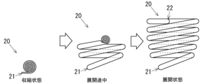
- FIG. 6A is a diagram showing the process in which an airbag changes from a flat folded state to an deployed state.
- FIG. 6B is a diagram showing the process in which the airbag changes from a spirally folded state to an deployed state.
- FIG. 7 is a diagram showing the process in which the airbag changes from a folded bellows state to an deployed state.
- FIG. 6A is a diagram showing the process in which an airbag changes from a flat folded state to an deployed state.
- FIG. 6B is a diagram showing the process in which the airbag changes from a spirally
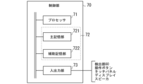
- FIG. 8 is a diagram showing the configuration of the control unit.
- FIG. 9 is a diagram showing a process flow of a protection method executed by the control unit of the protection device.
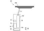
- FIG. 10 is a front view showing a state in which the airbag of the protection device according to the second embodiment is in a folded position.
- FIG. 11 is a diagram showing a schematic configuration of a protection device according to the second embodiment.
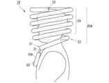
- FIG. 12 is a side view showing a state in which the airbag of the protection device according to the second embodiment is deployed.
- FIG. 13 is a side view showing a state in which the airbag of the protection device according to the third embodiment is in a folded position.
- FIG. 14 is a diagram showing a schematic configuration of a protection device 1B according to a third embodiment.
- FIG. 15 is a side view showing a state in which the airbag of the protection device according to the third embodiment is deployed.
- FIG. 16 is a diagram showing a configuration of a protection device according to a fourth embodiment.
- FIG. 17 is a diagram showing a configuration of a protection device according to a fifth embodiment.
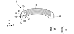
- FIG. 1 is a side view of the protection device 1 according to the first embodiment
- FIG. 2 is a schematic cross-sectional view of the protection device 1 according to the first embodiment
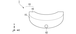
- FIG. 3 is a front view of the protection device 1 according to the first embodiment
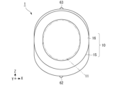
- FIG. 4 is a plan view of the protection device 1 according to the first embodiment. Note that FIGS. 1 to 4 show a state before the airbag 20 is deployed (before activation).
- FIG. 5 is a side view of the protection device 1 in a state in which the airbag 20 is deployed (when activated).
- the up-down direction is also referred to as the Y-axis direction
- the left-right direction is also referred to as the X-axis direction
- the depth direction is also referred to as the Z-direction.
- the up-down direction and the XYZ-axis directions of the protection device 1 merely show an example of the relative positional relationship of each element in the protection device 1 for the convenience of explaining the embodiment, and are not limited thereto.
- the posture when using the protection device 1 is not limited to the direction shown in the figure.
- the size of the protection device 1 with respect to the human body is not limited to that shown in the figure.
- the protection device 1 comprises a base section (attachment section) 10, an airbag 20, an inflator 30, a detection section 60, a control section 70, and a power source 80.
- the protection device 1 is attached to a user of the protection device 1 (hereinafter also simply referred to as a user), and protects at least a part of the user's body as a protection target area by deploying the airbag 20.
- a predetermined condition for protection hereinafter also referred to as an emergency
- the protection device 1 protects the user's protection target area by deploying the airbag 20.
- the base part 10 is attached to the user and includes a main body part 15 that houses the airbag 20, the inflator (fluid supply part) 30, the detection part 60, the control part 70, and the power source 80, and a cover part 16 that can be opened and closed with respect to the main body part 15.
- the base part 10 of this embodiment is formed in a roughly O-shape in a plan view so as to surround the user's head, and the space (protected side space) 11 near the center of the O-shape is formed to be larger than the user's head and smaller than the user's shoulder width.
- the protection device 1 is positioned on the user's shoulder and roughly below the head.
- the protection device 1 of this embodiment is a neck-hanging type that is used by hanging it around the user's neck.
- the protection device 1 is not limited to a neck-hanging type, and may be worn on the upper body of the user like a jacket, or may be fixed to the user with a belt or the like.
- the protection device 1 is also not limited to being worn around the neck, and may be worn on other parts of the body, such as the lower body, arms, legs, wrists, or head of the user.
- the protection device 1 may be indirectly worn by the user when the user wears the wearing equipment, such as a helmet, harness, or safety belt, by attaching the base unit 10 to the wearing equipment worn by the user.
- the base portion 10 is a container (housing) that forms the outer shell of the protection device 1 and houses the airbag 20, the inflator 30, the control unit 70, and the power source 80.
- the base portion 10 only needs to house at least one of the airbag 20, the inflator 30, the control unit 70, and the power source 80, and some of these may be provided outside the base portion.
- the airbag 20 is formed into a bag shape by joining together sheets of cloth or synthetic resin, and inflates when fluid is supplied from the inflator 30 to the internal space of the bag.
- the airbag 20 is provided on the base part 10 in a contracted state when it maintains its initial state, in other words, the state before it is inflated (hereinafter also referred to as standby).
- the airbag 20 of this embodiment receives fluid from the inflator 30 and inflates (hereinafter also referred to as inflating), it deploys in a spiral shape to surround the area to be protected.
- the airbag 20 deploys such that one end (first end) 21 is fixed to the base part 10, and the other end (second end) 22 opposite to the first end 21 detaches from the base part 10 when inflated.
- the user's neck and head are the areas to be protected, and the airbag 20 is wound around the neck and head in a spiral shape multiple times around a virtual axis that passes through the approximate center of the neck and head as the winding center. That is, the airbag 20 is formed longitudinally in the winding direction, has a peripheral wall that defines a continuous internal space along the winding direction, and when this internal space is filled with fluid, the peripheral wall is shaped into a spiral shape by the pressure of the fluid. Also, as shown in FIG. 5, the airbag 20 has a neck covering part 23 that covers the neck of the user when inflated, and a head covering part 24 that covers the user's head when inflated.
- the contracted state of the airbag 20 is not particularly limited, and may be, for example, a flat folded state or a bellows folded state.
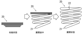
- FIG. 6A is a diagram showing the process in which the airbag 20 changes from a flat folded state to an expanded state.
- the airbag 20 In the pre-expansion state (contracted state) of FIG. 6A, the airbag 20 does not have any fluid inside and is compressed vertically, i.e., is folded flat, with each part that rotates in a spiral shape stacked vertically.
- the inflator 30 is activated and starts to supply fluid from the inflator 30, the airbag 20 starts to expand from the first end 21 side, and becomes expanded when the inside is filled with fluid.
- FIG. 6A in order to explain the expansion process, an intermediate process is shown in which the first end 21 side is inflated and the second end 22 side is not fully inflated.
- the contracted state of the airbag 20 may be such that the flat airbag 20 is rolled from the second end 22 side and rolled up to the first end 21 side so that the side is in a spiral shape as shown in FIG. 6A. That is, the airbag 20 may be one that contracts in a spiral shape like a so-called blowback whistle and deploys (inflates) when fluid is supplied.
- FIG. 6B is a diagram showing the process in which the airbag 20 changes from a spirally folded state to a deployed state. In the state before deployment in FIG.
- the airbag 20 does not have fluid inside and is compressed up and down, that is, is folded in a flat shape, and is rolled up from the second end 22 side along the longitudinal direction (rolling direction) and is in a spirally rolled state up to the first end 21 (contracted state). Then, when the inflator 30 is activated and the supply of fluid from the inflator 30 begins, the airbag 20 is filled with fluid from the first end 21 side, causing the rolled spiral part to expand into a cylindrical shape and stretching the spiral part in the rolling direction.
- the airbag 20 instantly deploys from a contracted state to a deployed state, but in order to explain the deployment process, the first end 21 side is inflated and the second end 22 side is not fully inflated and is in a spiral state during the deployment process in Figure 6B.
- the airbag 20 deploys in a spiral shape, just like in Figure 6A.
- FIG. 7 is a diagram showing the process in which the airbag 20 changes from a folded bellows-like state to a deployed state.
- the airbag 20 does not contain any fluid inside and is folded flat, and is then folded vertically at a predetermined width WA to form a mountain fold 211.
- the airbag 20 is folded vertically at the same width WA adjacent to the mountain fold 211 to form a valley fold 212.
- the airbag 20 is folded bellows-like and contracted in the longitudinal direction (rolling direction).
- the airbag 20 When the inflator 30 starts to supply fluid due to the operation of the inflator 30, the airbag 20 starts to inflate from the first end 21 side, as in the case of FIG. 6A, and is deployed as the fluid fills the inside.
- the airbag 20 may have a supply hole for receiving the supply of fluid from the inflator 30, as well as a discharge hole for discharging the fluid. After deployment, the airbag 20 may be configured to discharge fluid through the exhaust hole, return to a deflated state, and be reused.
- the inflator 30 is connected to the airbag 20 via the air supply pipe 31, and supplies fluid to the airbag 20 when activated under the control of the control unit 70.
- the inflator 30 burns gunpowder, for example, to generate combustion gas, and supplies this combustion gas (fluid) to the airbag 20.
- the inflator 30 is not limited to this, but may be equipped with a tank containing compressed gas and supply the gas (fluid) released from the tank to the airbag 20, or may be a combination of these to supply the combustion gas and the released gas to the airbag 20.
- the inflator 30 may be configured, for example, with the gunpowder, which is the fluid supply source, and the tank for the compressed gas as a cartridge type that is replaceable.
- the detection unit 60 is a means for detecting the state of the user and the state of the user's surroundings, and includes, for example, sensing means such as an acceleration sensor, a gyro sensor (angular velocity sensor), a positioning device, a camera, a radar, a LIDAR (Light Detection and Ranging, Laser Imaging Detection and Ranging), a three-dimensional scanner, a temperature sensor, a humidity sensor, a contact sensor, and an infrared sensor.
- sensing means such as an acceleration sensor, a gyro sensor (angular velocity sensor), a positioning device, a camera, a radar, a LIDAR (Light Detection and Ranging, Laser Imaging Detection and Ranging), a three-dimensional scanner, a temperature sensor, a humidity sensor, a contact sensor, and an infrared sensor.
- sensing means such as an acceleration sensor, a gyro sensor (angular velocity sensor), a positioning device, a camera, a
- the detection unit 60 may detect a change in the user's state, such as when the user falls or collides with another object, or may predict that the user will receive an impact.
- the detection unit 60 may also detect a change in the state of objects present around the user, such as an object approaching the user and likely to collide with the user, or an object that has collided with the user.
- An example of a positioning device is a satellite positioning system such as GPS (Global Positioning System).
- GPS Global Positioning System
- the radar and LIDAR determine the distance to objects around the protection device 1 (user) and the moving speed of those objects.
- the first detection unit 60 includes an acceleration sensor 61 that detects the acceleration of the protective device 1, i.e., the acceleration of the user wearing the protective device 1.
- the acceleration sensor 61 detects the rate of change of speed in a predetermined axis (for example, three axes in the X, Y, and Z directions) and the direction as the acceleration of each axis.
- the acceleration sensor 61 may be a so-called six-axis sensor that also serves as a sensor for detecting angular velocity in these axes.
- the front part of the base unit 10 is provided with a camera 62 as a second detection unit 60, which captures an image in front of the user and inputs the captured image to the control unit 70 as information indicating the state of the user's surroundings.
- the camera 62 may be a stereo camera that captures the same subject (object) with a pair of imaging units arranged at a predetermined distance (baseline length) and can detect the distance to the subject from the parallax. Furthermore, the rear part of the base unit 10 is provided with a camera 63 as a third detection unit 60, which captures an image behind the user and outputs the captured image to the control unit 70 as information indicating the state of the user's surroundings.
- Camera 63 may be a stereo camera, like camera 62. Cameras 62 and 63 arranged in front and behind each other in this manner capture images with an angle of view of 180 degrees or more, for example, to capture the entire surroundings around the user.
- detection unit 60 may be provided with other components besides acceleration sensor 61 and cameras 62 and 63.
- the control unit 70 operates by receiving power from the power source 80, and controls the detection unit 60 and the inflator 30.
- the control unit 70 for example, acquires the detection result by the detection unit 60, and controls the inflator 30 to activate the protection device 1 when the detection result satisfies a predetermined condition.
- Figure 8 is a diagram showing the configuration of the control unit 70.
- the control unit 70 includes a processor 71, a memory unit 72, and an input/output unit 73.
- the processor 71 comprehensively executes various types of arithmetic processing in the control unit 70.
- the processor 71 is an arithmetic processing means such as a CPU (Central Processing Unit), a DSP (Digital Signal Processor), or an FPGA (Field-Programmable Gate Array).
- the memory unit 72 includes, for example, a main memory unit 721 and an auxiliary memory unit 722.
- the main memory unit 721 includes a main memory unit such as a RAM (Random Access Memory) or a ROM (Read Only Memory), and caches information such as programs and data used for arithmetic processing by the processor 71.
- the main memory unit 721 may be formed integrally with the processor 71.
- the auxiliary memory unit 722 is composed of storage media such as volatile memory such as RAM, non-volatile memory such as ROM, EPROM (Erasable Programmable ROM), a hard disk drive (HDD, Hard Disk Drive), or removable media.
- volatile memory such as RAM
- non-volatile memory such as ROM, EPROM (Erasable Programmable ROM), a hard disk drive (HDD, Hard Disk Drive)
- removable media is a recording medium that can be attached externally and is computer-readable, such as a Universal Serial Bus (USB) memory or a memory card.
- USB Universal Serial Bus
- the auxiliary memory unit 722 can store an operating system (OS), various programs, various tables, various databases, user data, and the like, for executing the operations of the protection device 1.
- OS operating system
- the input/output unit 73 is, for example, an interface that inputs information (detection results, etc.) from the detection unit 60 and outputs information (control signals, etc.) to the detection unit 60 or other devices.
- the input/output unit 73 may also be a communication module that inputs (receives) information from other devices and outputs (transmits) information to other devices.
- the input/output unit 73 may be a user interface that inputs operation information by the user via an operation button, touch panel, etc., and outputs (displays, outputs sound, etc.) to the user via a display, speaker, etc.
- Fig. 9 is a diagram showing a processing flow of a protection method executed by the control unit 70 of the protection device 1.
- the protection device 1 repeatedly executes the processing (operation steps) of Fig. 9 while the power is ON or when a start-up instruction is received.
- step S10 the control unit 70 acquires the user's state and the surrounding state from the detection unit 60.
- the control unit 70 acquires the user's acceleration from the acceleration sensor 61, and detects captured images of the surroundings from the cameras 62 and 63.
- step S20 the control unit 70 analyzes the state of the user and the state of the user's surroundings based on the detection result of the detection unit 60 obtained in step S10. For example, the control unit 70 obtains information indicating the state of the user, such as the user's moving direction, moving speed, rate of change of acceleration per unit time (jerk), and inclination with respect to the direction of gravity, based on the acceleration of each axis detected by the acceleration sensor 61. In addition, the control unit 70 extracts objects present around the user by processing the images taken by the cameras 62 and 63, and obtains the position, moving direction, moving speed, etc. of the objects as surrounding information.
- the control unit 70 extracts objects present around the user by processing the images taken by the cameras 62 and 63, and obtains the position, moving direction, moving speed, etc. of the objects as surrounding information.
- control unit 70 may detect the user's actions, such as the user walking, sitting, running, riding a bicycle, or stopping, based on the images taken by the cameras 62 and 63.
- the method of obtaining the position, speed, moving direction, etc. of an object from the captured image can use known technology, so detailed explanations will be omitted.
- the position, speed, and direction of movement of an object may be obtained not only by the cameras 62 and 63, but also by radar, LIDAR, a three-dimensional scanner, or a combination of these.
- step S30 the control unit 70 determines whether to activate the protection device 1 depending on whether the information indicating the user's state and the surrounding state obtained in step S20 satisfies a predetermined condition. For example, if the user collides with something or is hit by a vehicle or the like and receives an impact, this impact is detected as a sudden change in acceleration, so the control unit 70 determines (positive determination) that the user has received an impact and that the protection device 1 is to be activated if the jerk obtained in step S20 exceeds a predetermined threshold.
- control unit 70 determines in step S20 that the user's head has moved downward at an acceleration exceeding a predetermined threshold, it makes a positive determination that the user has fallen, that is, that the head may be impacted. Furthermore, the control unit 70 makes a positive determination when the user's position after a predetermined time coincides with the position of a surrounding object, that is, when the object collides with the user, based on the object's position, moving direction, moving speed, etc. obtained in step S20. Note that these conditions and thresholds may be set by the user's operation.
- the control unit 70 may determine whether the protection device 1 is attached to the user based on the detection result of the detection unit 60, such as a contact sensor or an infrared sensor, and may not activate the protection device 1 if the protection device 1 is not attached to the user, regardless of the presence or absence of an impact. Also, based on the detection result of the detection unit 60, such as a positioning device or an acceleration sensor, it may determine whether the protection device 1 (user) is moving, and may not activate the protection device 1 if the user is not moving.
- the detection result of the detection unit 60 such as a positioning device or an acceleration sensor
- step S30 If the information indicating the user's condition and the surrounding condition does not satisfy the predetermined conditions and a negative judgment is made in step S30, the control unit 70 ends the processing in FIG. 9. On the other hand, if a positive judgment is made in step S30, the control unit 70 proceeds to step S40 and activates the inflator 30. This causes the inflator 30 to supply fluid to the airbag 20, detaching the second end 22 of the airbag 20 from the base portion 10 and deploying the airbag 20 in a spiral shape, i.e., activating the protection device 1.
- the user may replace the fluid supply source of the inflator 30 and fold the airbag 20 to store it in the base portion 10, allowing the protection device 1 to be reused.
- the protection device 1 can protect the user's protected area by deploying the airbag 20 in a spiral shape to surround the protected area.
- the airbag 20 of the present embodiment is configured to deploy in a spiral shape, the volume of the airbag 20 is smaller than that of a configuration that entirely covers the protected area, and the amount of fluid for deploying the airbag 20 can be reduced. This shortens the period from when fluid starts to be supplied to the airbag 20 until the fluid required for deployment is supplied, and the deployment speed of the airbag 20 can be improved.
- the smaller volume of the airbag 20 can reduce the supply source of the inflator 30, and the device can be made smaller.
- the protective device 1 of this embodiment has an airbag 20 that has a neck covering part 23 that covers the user's neck when inflated, and a head covering part 24 that covers the user's head when inflated.
- the neck covering part 23 and head covering part 24 that are deployed in a spiral shape wrap around the user's neck and head, respectively, and restrain the neck and head, thereby suppressing movement of the neck and head and suppressing damage to the cervical vertebrae, muscles and ligaments around the neck, etc.
- the airbag 20 is attached to the base 10 while it is on standby, folded into a bellows shape or flat shape, and when inflated, it surrounds the neck and head of the user in a spiral shape.
- the protective device 1 of this embodiment is large enough for the airbag 20 to surround the neck and head when activated, while being stored compactly while on standby, allowing for a more compact device.
- FIG. 10 is a front view showing the airbag 20A of the protection device 1A according to the second embodiment in a folded position
- FIG. 11 is a diagram showing the general configuration of the protection device 1 according to the second embodiment
- FIG. 12 is a side view showing the airbag 20A of the protection device 1A according to the second embodiment in an deployed position.
- the protective device 1A of this embodiment is different in that the airbag 20A is disposed outside the base portion 10A, and the airbag 20A in a deflated state is worn by hanging it around the user's neck, but the rest of the configuration is the same. For this reason, the same elements as in the previous embodiment are given the same reference numerals, and repeated explanations will be omitted.
- the base portion 10A is attached to the user and includes a main body portion 15A that houses the inflator 30, the detection portion 60, the control portion 70, and the power source 80.
- the first end 21 of the airbag 20A is connected to the inflator 30 via an air supply pipe 31. That is, the first end 21 of the airbag 20A is connected to the base portion 10A, and the airbag 20A is attached to the user via the base portion 10A.
- the airbag 20A is folded flat, and the spirally wound portions are stacked vertically to be in a deflated state.
- the control unit 70 determines to activate the protection device 1A and controls the inflator 30 to supply fluid to the airbag 20A
- the airbag 20A inflates in a spiral shape and deploys to surround the user's neck and head, as shown in FIG. 12.
- the protection device 1A of this embodiment can protect the areas of the user that need to be protected (neck and head).
- the protection device 1A of this embodiment has the base part 10A and the airbag 20A configured separately, there is more freedom in the position at which the base part 10A is attached, improving convenience.
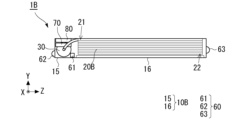
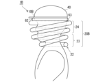
- Third Embodiment Figure 13 is a side view showing the airbag 20B of the protection device 1B according to the third embodiment in a folded position
- Figure 14 is a diagram showing the general configuration of the protection device 1B according to the third embodiment
- Figure 15 is a side view showing the airbag 20B of the protection device 1B according to the third embodiment in an deployed position.
- the protective device 1B of this embodiment is different in that the base portion 10B is attached to the helmet 40, and the protective device 1B is worn by the user via the helmet 40, but the other configurations are the same. For this reason, the same elements as those in the first embodiment described above are given the same reference numerals, and repeated explanations will be omitted.
- the base portion 10B is attached to the bottom of the helmet 40 and includes a main body portion 15 that houses the airbag 20B, inflator 30, detection portion 60, control portion 70, and power source 80, and a lid portion 16 that can be opened and closed relative to the main body portion 15.
- the protective device 1B of this embodiment is arranged upside down compared to the protective device 1 of the first embodiment, and when activated, the airbag 20B is deployed downward from the base portion 10B. For this reason, the head covering portion 24 is arranged on the first end 21 side of the airbag 20B that is connected to the inflator 30, and the neck covering portion 23 is arranged on the second end 22 side.
- the control unit 70 determines to activate the protective device 1B and controls the inflator 30 to supply fluid to the airbag 20B, the airbag 20B inflates in a spiral shape as shown in FIG. 15 and deploys to surround the user's neck and head.
- the protective device 1B of this embodiment can protect the areas of the user that need to be protected (neck and head).
- the protective device 1B of this embodiment can prevent the helmet 40 from slipping off the user's head because the airbag 20B, which is connected to the helmet via the base unit 10B, deploys to surround the user's neck and head.
- the base part 10B is configured to house the airbag 20B during standby, but this is not limiting. As shown in the second embodiment, the base part 10B may not house the airbag 20B, and the airbag 20B may be arranged outside the base part 10B. In this case, the first end 21 of the base part 10B may be fixed to the lower part of the helmet 40, and the airbag 20B in a deflated state during standby may be attached to the lower part of the helmet 40 by a fastener such as a snap button or a hook-and-loop fastener.
- a fastener such as a snap button or a hook-and-loop fastener.
- This fastener holds the airbag 20B in a deflated state to the helmet 40 so that it does not fall downward, and releases the lock when a force of a predetermined value or more is applied in the direction in which the airbag 20B is deployed. That is, when fluid is supplied to the airbag 20B, the airbag 20B begins to inflate and a force is applied to the fastener, the fastener is released and the airbag 20B deploys downward.
- ⁇ Fourth embodiment> 16 is a diagram showing the configuration of a protection device 1C according to a fourth embodiment.
- the protection device 1C of this embodiment is different from the first embodiment in that it has an expandable member 50 that expands and contracts the airbag 20C, but the other configurations are the same. For this reason, the same elements as those in the first embodiment are given the same reference numerals, and repeated explanations will be omitted.
- the elastic member 50 is a coil spring provided on the outer surface of the airbag 20C along the winding direction of the airbag 20C.
- the elastic member 50 may be provided inside the airbag 20C along the winding direction of the airbag 20C.
- the elastic member 50 is a so-called tension spring, and is in a contracted state in the contraction direction when no load is applied. Since the elastic member 50 of this embodiment is provided on the airbag 20C along the winding direction of the airbag 20C, when the elastic member 50 is in a contracted state, the airbag 20C is also in a contracted state, that is, in a flat folded state.
- the elastic member 50 is not limited to a coil spring, and may be other springs, rubber, actuators, etc., as long as it contracts and expands together with the airbag 20C and contracts the airbag 20C after the airbag 20C is deployed.
- the control unit 70 determines that the protection device 1C should be activated and controls the inflator 30 to supply fluid to the airbag 20C
- the airbag 20B inflates in a spiral shape as shown in FIG. 16, stretching the elastic member 50 and deploying to surround the user's neck and head.
- the elastic member 50 is stretched, and an elastic force acts in the contracting direction, biasing the airbag 20 in a direction to contract toward the base portion 10.
- the airbag 20C is contracted by the biasing force of the elastic member 50. As a result, the airbag 20C is automatically housed within the base portion 10 after deployment.
- the protective device 1C of this embodiment automatically contracts the airbag 20C and folds it into a flat shape, which reduces the effort required to contract the airbag 20C when reusing it, improving convenience.
- the elastic member 50 is a tension spring
- the elastic member 50 may be a compression spring that biases the airbag 20C in a direction that causes the second end 22 of the airbag 20C to separate from the base portion 10, thereby assisting in the deployment of the airbag 20C when the inflator 30 is activated.
- Fifth Embodiment 17 is a diagram showing the configuration of a protection device 1D according to a fifth embodiment.
- the protection device 1D of this embodiment is different from the first embodiment in that the airbag 20D has a sub-path that connects the main path in the up-down direction in addition to the main path of the fluid extending in the rolling direction, but the other configurations are the same. Therefore, the same elements as those in the first embodiment are denoted by the same reference numerals, and repeated explanations will be omitted.
- the airbag 20D of this embodiment When the airbag 20D of this embodiment is supplied with fluid from the inflator 30, the fluid flows from the first end 21 side to the second end 22 side, and the airbag 20D is deployed in a spiral shape.
- the airbag 20D has a main path 25 as a path through which the fluid flows in the winding direction of the spiral.
- the main path 25 deploys around the central axis of the spiral, and when the airbag 20D is fully inflated, it inflates to surround the area to be protected in a spiral shape.
- the airbag 20D also has a sub-path 26 as a path that connects multiple points of the main path 25 wound multiple times in this winding direction in the vertical direction (axial direction of the central axis).
- the sub-path 26 is shorter than the main path 25, and can supply fluid to the second end 22 side more quickly.
- the sub-path 26 also functions as a tether that maintains a predetermined distance between the main paths 25 located above and below.
- the sub-path 26 may be formed to have a smaller cross-sectional area than the main path 25.
- the protection device 1D of this embodiment can improve the deployment speed of the airbag 20D because the airbag 20D has the sub-path 26 in addition to the main path 25. Furthermore, the sub-path 26 of the airbag 20D maintains a predetermined distance between the main paths 25 located above and below, thereby stabilizing the shape of the airbag 20D when deployed and improving the reliability of the protection device 1D.
Landscapes
- Health & Medical Sciences (AREA)
- General Health & Medical Sciences (AREA)
- Physical Education & Sports Medicine (AREA)
- Engineering & Computer Science (AREA)
- Textile Engineering (AREA)
- Professional, Industrial, Or Sporting Protective Garments (AREA)
Abstract
利用者の体の少なくとも一部を保護対象部位とする保護装置が、前記利用者に装着される装着部と、待機時において収縮状態で前記装着部に取り付けられ、膨張完了時に前記保護対象部位の周囲を渦巻き状に囲うように展開するエアバッグであり、前記エアバッグの一端が前記装着部に固定され、膨張時に前記一端とは反対側の他端が前記装着部から離脱して展開するエアバッグと、前記エアバッグを膨張させる流体を前記エアバッグ内に供給する流体供給部と、前記利用者の状態が所定条件を満たした際に前記流体供給部を作動させる制御を行う制御部とを含む。
Description
本発明は、保護装置及び保護方法に関する。
特許文献1には、エアバッグ収納具と、鍔部と、あご紐と、エアバッグと、機器収納部とを備えるエアバッグ装置が記載されている。当該装置のエアバッグは、利用者の前頭部を被覆可能な前頭部被覆部と、利用者の左右の側頭部を被覆可能な左右一対の側頭部被覆部と、利用者の後頭部を被覆可能な後頭部被覆部と、利用者の頭頂部を被覆可能な頭頂部被覆部とを有している。
特許文献1のように、エアバッグを展開した際に頭部の周囲を全体的に覆う構成とした場合、エアバッグが大型化し、当該エアバッグを展開させるガスの量が多くなるため、ガスを供給展開に時間がかかるという問題があった。
本開示の技術は、上記した実情に鑑みてなされたものであり、エアバッグの速やかな展開を可能にする技術の提供を目的とする。
上記課題を解決するために、本開示は、
利用者の体の少なくとも一部を保護対象部位とする保護装置であって、
前記利用者に装着される装着部と、
待機時において収縮状態で前記装着部に取り付けられ、膨張完了時に前記保護対象部位の周囲を渦巻き状に囲うように展開するエアバッグであり、前記エアバッグの一端が前記装着部に固定され、膨張時に前記一端とは反対側の他端が前記装着部から離脱して展開するエアバッグと、
前記エアバッグを膨張させる流体を前記エアバッグ内に供給する流体供給部と、
前記利用者の状態が所定条件を満たした際に前記流体供給部を作動させる制御を行う制御部と、を含む。
利用者の体の少なくとも一部を保護対象部位とする保護装置であって、
前記利用者に装着される装着部と、
待機時において収縮状態で前記装着部に取り付けられ、膨張完了時に前記保護対象部位の周囲を渦巻き状に囲うように展開するエアバッグであり、前記エアバッグの一端が前記装着部に固定され、膨張時に前記一端とは反対側の他端が前記装着部から離脱して展開するエアバッグと、
前記エアバッグを膨張させる流体を前記エアバッグ内に供給する流体供給部と、
前記利用者の状態が所定条件を満たした際に前記流体供給部を作動させる制御を行う制御部と、を含む。
前記保護装置は、前記流体供給部の作動時に前記エアバッグの前記他端を前記装着部から離脱させる方向に前記エアバッグを付勢する、又は前記エアバッグの膨張後に、前記エアバッグを前記装着部側へ収縮させる方向に前記エアバッグを付勢する伸縮部材を有してもよい。
前記保護装置は、前記エアバッグが、前記膨張完了時に前記利用者の頸部を被覆する頸部被覆部、及び膨張時に前記利用者の頭部を被覆する頭部被覆部を有してもよい。
前記保護装置は、前記エアバッグが、前記利用者の頭部に装着されるヘルメットと接続され、
当該ヘルメットと接続された前記エアバッグが、前記膨張完了時に前記利用者の頭部を囲むように展開することにより、前記ヘルメットのズレを抑制してもよい。
当該ヘルメットと接続された前記エアバッグが、前記膨張完了時に前記利用者の頭部を囲むように展開することにより、前記ヘルメットのズレを抑制してもよい。
前記保護装置は、前記エアバッグが、
待機時において、渦巻き状、蛇腹状又は平面状に折り畳まれて前記装着部に取り付けられ、
膨張時に前記利用者の頸部と頭部の周囲を渦巻き状に囲ってもよい。
待機時において、渦巻き状、蛇腹状又は平面状に折り畳まれて前記装着部に取り付けられ、
膨張時に前記利用者の頸部と頭部の周囲を渦巻き状に囲ってもよい。
前記保護装置は、前記エアバッグが、
前記流体の供給により前記渦巻の中心軸に対して軸回りに展開し、前記膨張完了時に前記保護対象部位の周囲を渦巻き状に囲うように膨張する主経路と、
前記渦巻き状に展開する主経路における複数個所を前記中心軸の軸方向に連通する副経路と、
を備えてもよい。
前記流体の供給により前記渦巻の中心軸に対して軸回りに展開し、前記膨張完了時に前記保護対象部位の周囲を渦巻き状に囲うように膨張する主経路と、
前記渦巻き状に展開する主経路における複数個所を前記中心軸の軸方向に連通する副経路と、
を備えてもよい。
前記保護装置は、前記装着部が、前記流体供給部又は前記制御部を収容する筐体であり、前記エアバッグが、前記筐体外に設けられてもよい。
上記課題を解決するために、本開示は、
利用者の体の少なくとも一部を保護対象部位とし、前記利用者に装着される装着部と、待機時において収縮状態で前記装着部に取り付けられるエアバッグと、前記エアバッグを膨張させる流体を前記エアバッグ内に供給する流体供給部と、前記流体供給部の制御を行う制御部とを備える保護装置が実行する保護方法であって、
前記利用者の状態が所定条件を満たした際に、前記制御部が前記流体供給部を作動させ、
前記流体供給部が、前記作動により前記エアバッグ内に流体を供給し、
一端が前記装着部に固定された前記エアバッグが、前記流体の供給を受けて、前記一端とは反対側の他端が前記装着部から離脱して展開し、膨張完了時に前記保護対象部位の周囲を渦巻き状に囲う。
利用者の体の少なくとも一部を保護対象部位とし、前記利用者に装着される装着部と、待機時において収縮状態で前記装着部に取り付けられるエアバッグと、前記エアバッグを膨張させる流体を前記エアバッグ内に供給する流体供給部と、前記流体供給部の制御を行う制御部とを備える保護装置が実行する保護方法であって、
前記利用者の状態が所定条件を満たした際に、前記制御部が前記流体供給部を作動させ、
前記流体供給部が、前記作動により前記エアバッグ内に流体を供給し、
一端が前記装着部に固定された前記エアバッグが、前記流体の供給を受けて、前記一端とは反対側の他端が前記装着部から離脱して展開し、膨張完了時に前記保護対象部位の周囲を渦巻き状に囲う。
本開示によれば、エアバッグの速やかな展開を可能とする技術を提供できる。
以下に、図面を参照して本開示の実施形態に係る保護装置が説明される。なお、実施形態における各構成及びそれらの組み合わせ等は、一例であって、本開示の主旨から逸脱しない範囲内で、適宜、構成の付加、省略、置換、及びその他の変更が可能である。本開示は、実施形態によって限定されることはなく、特許請求の範囲によってのみ限定される。
<第一実施形態>
図1は、第一実施形態に係る保護装置1の側面図、図2は、第一実施形態に係る保護装置1の模式断面図、図3は、第一実施形態に係る保護装置1の正面図、図4は、第一実施形態に係る保護装置1の平面図である。なお、図1~図4は、エアバッグ20を展開する前(作動前)の状態を示す。図5は、エアバッグ20を展開した状態(作動時)における保護装置1の側面図である。本明細書では、上下方向がY軸方向、左右方向がX軸方向、奥行き方向がZ方向とも称される。但し、本明細書において保護装置1の上下方向及びXYZ軸方向は、実施形態の説明の便宜上、保護装置1における各要素の相対的な位置関係等の一例を示すものに過ぎず、これに限定されるものではない。例えば、保護装置1を使用する際の姿勢は、図に示した方向に限定されるものではない。また人体に対する保護装置1の大きさも図に限られるものではない。
図1は、第一実施形態に係る保護装置1の側面図、図2は、第一実施形態に係る保護装置1の模式断面図、図3は、第一実施形態に係る保護装置1の正面図、図4は、第一実施形態に係る保護装置1の平面図である。なお、図1~図4は、エアバッグ20を展開する前(作動前)の状態を示す。図5は、エアバッグ20を展開した状態(作動時)における保護装置1の側面図である。本明細書では、上下方向がY軸方向、左右方向がX軸方向、奥行き方向がZ方向とも称される。但し、本明細書において保護装置1の上下方向及びXYZ軸方向は、実施形態の説明の便宜上、保護装置1における各要素の相対的な位置関係等の一例を示すものに過ぎず、これに限定されるものではない。例えば、保護装置1を使用する際の姿勢は、図に示した方向に限定されるものではない。また人体に対する保護装置1の大きさも図に限られるものではない。
保護装置1は、ベース部(装着部)10、エアバッグ20、インフレータ30、検出部60、制御部70、及び電源80を備えている。保護装置1は、保護装置1の利用者(以下、単にユーザとも称す)に装着され、利用者の体の少なくとも一部を保護対象部位と、エアバッグ20を展開して、保護対象部位を保護する。例えば、保護装置1は、検出部60により、ユーザが転倒した場合や衝突が回避できない状態となった場合等、ユーザの状態が保護の所定条件を満たした場合(以下、非常時とも称す)に、エアバッグ20を展開することによってユーザの保護対象部位を保護する。
ベース部10は、ユーザに装着され、エアバッグ20、インフレータ(流体供給部)30、検出部60、制御部70、及び電源80を収容する本体部15と、本体部15に対して開閉可能な蓋部16とを備えている。本実施形態のベース部10は、ユーザの頭部を囲むように平面視において概ねO字状に形成され、O字の中心付近の空間(保護対象側空間)11がユーザの頭部よりも大きく、且つユーザの肩幅よりも小さく形成されている。このため、ベース部10は、内側空間11にユーザの頭部が通されると、ベース部10の下面がユーザの肩に突き当たって止まり、ベース部10がユーザの首に掛けられた状態で装着される。換言すると、保護装置1は、ユーザの肩の上であって、頭部の概ね下側に配置される。このように、本実施形態の保護装置1は、ユーザの首にかけて用いられる首掛け型である。なお、保護装置1は、首掛け型に限らず、ジャケットのようにユーザの上半身に装着されるものや、ベルト等でユーザに固定されるものであってもよい。また、保護装置1は、首に装着されるものに限定されず、ユーザの下半身や、腕、足、手首、頭部など、他の部位に装着されるものであってもよい。また、保護装置1は、ヘルメットやハーネス、安全ベルト等といったユーザが装着する装着具にベース部10が取り付けられ、ユーザが当該装着具を装着することで、間接的にユーザに装着されるものであってもよい。
ベース部10は、保護装置1の外殻を成し、内部にエアバッグ20、インフレータ30、制御部70、及び電源80を収容する容器(筐体)である。なお、ベース部10は、エアバッグ20、インフレータ30、制御部70、及び電源80のうち、少なくとも一つを収容する構成であれば良く、これらのうち一部がベース部外に設けられてもよい。
エアバッグ20は、布や合成樹脂のシートを継ぎ合わせて袋状に形成され、当該袋の内部空間にインフレータ30から流体の供給を受けることで膨張する。エアバッグ20は、初期の状態、換言すると膨張される前の状態を維持しているとき(以下、待機時とも称す)に、収縮状態でベース部10に設けられている。本実施形態のエアバッグ20は、インフレータ30から流体の供給を受けて膨張したとき(以下、膨張時とも称す)に、保護対象部位の周囲を囲うように渦巻き状に展開する。なお、エアバッグ20は、一端(第一端)21がベース部10に固定され、膨張時に第一端21とは反対側の他端(第二端)22がベース部10から離脱するように展開する。本実施形態では、ユーザの頸部及び頭部を保護対象部位とし、エアバッグ20が、当該頸部及び頭部の概ね中心を通る仮想軸を巻回中心とし、この軸回りに頸部及び頭部の周囲を渦巻き状に複数回、巻き回される。即ち、エアバッグ20は、巻回方向に長手に形成され、この巻回方向に沿う一続きの内部空間を画す周壁を有し、この内部空間に流体が満たされると、この流体の圧力によって周壁が渦巻き状に形作られる。また、エアバッグ20は、図5に示されるように、膨張時にユーザの頸部を被覆する頸部被覆部23、及び膨張時にユーザの頭部を被覆する頭部被覆部24を有する。
エアバッグ20の収縮状態は、特段限定されるものではないが、例えば、平面状に畳まれた状態や、蛇腹状に折り畳まれた状態であってもよい。図6Aは、エアバッグ20が、平面状に畳まれた状態から展開状態に変化する過程を示す図である。図6Aの展開前の状態(収縮状態)では、エアバッグ20が、内部に流体を有さず、上下に押し縮められた状態、即ち平面状に折り畳まれた状態で、渦巻き状に周回する各部が上下に積み重ねられている。インフレータ30の作動により、インフレータ30から流体の供給が開始されると、エアバッグ20は、第一端21側から膨張し始め、内部に流体が満たされることで展開状態となる。なお、エアバッグ20は、収縮状態から展開状態へ瞬時に展開されるが、図6Aでは、展開の過程を説明するために、第一端21側が膨張し、第二端22側が膨張しきっていない途中過程を示している。
更に、エアバッグ20の収縮状態は、図6Aのように平面状のエアバッグ20が第二端22側から巻かれ、側面が渦巻き状となるように第一端21側に巻き取られたものであってもよい。即ち、エアバッグ20は、いわゆる吹き戻し笛のように渦巻き状に収縮し、流体の供給を受けて展開(膨張)するものであってもよい。図6Bは、エアバッグ20が、渦巻き状に畳まれた状態から展開状態に変化する過程を示す図である。図6Bの展開前の状態では、エアバッグ20が、内部に流体を有さず、上下に押し縮められた状態、即ち平面状に折り畳まれた状態で、第二端22側から長手方向(巻回方向)に沿って巻かれ、第一端21まで渦巻き状に巻かれた状態(収縮状態)となっている。そして、インフレータ30の作動により、インフレータ30から流体の供給が開始されると、エアバッグ20は、第一端21側から内部に流体が満たされることで、巻かれていた渦巻き部分が筒状に膨張し、渦巻き部分を巻回方向へ延伸させる。なお、エアバッグ20は、収縮状態から展開状態へ瞬時に展開されるが、展開の過程を説明するために、図6Bにおける途中過程では、第一端21側が膨張し、第二端22側が膨張しきらず渦巻き状の状態を示している。このように巻かれた部分が戻されて膨張しきると、エアバッグ20は、図6Aと同じくスパイラル状に展開する。
図7は、エアバッグ20が、蛇腹状に畳まれた状態から展開状態に変化する過程を示す図である。図7の展開前の状態では、エアバッグ20が、内部に流体を有さず、平面状に折り畳まれた状態で、更に所定の幅WAで上下に折り畳まれ、山折り部211が形成される。次にエアバッグ20は、山折り部211の隣接部分が同じ幅WAで上下反対に折り畳まれて、谷折り部212が形成される。この山折り部211と谷折り部212が交互に形成されることで、エアバッグ20が蛇腹状に畳まれ、長手方向(巻回方向)において収縮された状態となる。インフレータ30の作動により、インフレータ30から流体の供給が開始されると、エアバッグ20は、図6Aの場合と同様に、第一端21側から膨張し始め、内部に流体が満たされることで展開状態となる。エアバッグ20は、インフレータ30から流体の供給を受ける供給孔の他、流体を排出する排出孔を有してもよい。エアバッグ20は、展開後、排出孔から流体を排出し、収縮状態に戻され、再使用される構成であってもよい。
インフレータ30は、給気管31を介してエアバッグ20と接続され、制御部70の制御によって作動した場合に、エアバッグ20へ流体を供給する。インフレータ30は、例えば、作動時に火薬を燃焼させて、燃焼ガスを発生させ、この燃焼ガス(流体)をエアバッグ20へ供給する。これに限らずインフレータ30は、圧縮ガスを内蔵したタンクを備え、タンクから放出されたガス(流体)をエアバッグ20へ供給するものや、これらを組み合わせて、燃焼ガスと放出されたガスとをエアバッグ20へ供給するものであってもよい。インフレータ30は、例えば、流体の供給源である火薬や、圧縮ガスのタンクをカートリッジ式とし、交換可能に構成してもよい。
検出部60は、ユーザの状態やユーザの周囲の状態を検出する手段であり、例えば、加速度センサ、ジャイロセンサ(角速度センサ)、測位装置、カメラ、レーダ、LIDAR(Light Detection and Ranging、Laser Imaging Detection and Ranging)、三次元スキャナ、温度センサ、湿度センサ、接触センサ、赤外線センサなどの感知手段を含むものである。なお、本実施形態では、ユーザの周囲を走行している車両の状態など、ユーザの周囲の状態についても、ユーザの状態と称す。検出部60は、ユーザが転倒した場合や、ユーザが他の物体と衝突した場合など、ユーザの状態変化を検出するものや、ユーザが衝撃を受けることを予測するものであってもよい。また、検出部60は、ユーザに接近し、ユーザに衝突しそうな物体や、衝突した物体など、ユーザの周囲に存在する物体の状態変化を検出するものであってもよい。測位装置としては、例えばGPS(Global Positioning System)等の衛星測位システムが挙げられる。レーダ及びLIDARは、保護装置1(ユーザ)の周囲に存在する物体との距離や、当該物体の移動速度を求める。
本実施形態では、保護装置1の加速度、即ち保護装置1を装着したユーザの加速度を検出する加速度センサ61を第一の検出部60として備えている。加速度センサ61は、所定の軸(例えばXYZ方向の三軸)における速度の変化率と、その方向を各軸の加速度として検出する。加速度センサ61は、これらの軸における角速度を検出するセンサを兼ねた所謂六軸センサであってもよい。ベース部10の前側部分には、カメラ62が第二の検出部60として備えられ、ユーザの前方を撮影して、その撮影画像をユーザの周囲の状態を示す情報として制御部70へ入力する。なお、カメラ62は、所定の距離(基線長)を隔てて配置した一対の撮像ユニットで同一の被写体(物体)を撮影し、その視差から被写体までの距離等を検出できるステレオカメラであってもよい。更に、ベース部10の後側部分にはカメラ63が第三の検出部60として備えられ、ユーザの後方を撮影して、その撮影画像をユーザの周囲の状態を示す情報として制御部70へ出力する。カメラ63は、カメラ62と同様に、ステレオカメラであってもよい。このように前後に配置されたカメラ62,63は、例えば夫々が180度以上の画角で撮影を行うことで、ユーザを中心とした全周囲を撮影する。なお、図では省略したが、加速度センサ61、カメラ62,63以外の検出部60を備えてもよい。
制御部70は、電源80から電力の供給を受けて動作し、検出部60やインフレータ30を制御する。制御部70は、例えば、検出部60による検出結果を取得し、検出結果が所定条件を満たした場合にインフレータ30を制御して、保護装置1を作動させる。図8は、制御部70の構成を示す図である。制御部70は、プロセッサ71、記憶部72、及び入出力部73を備える。プロセッサ71は、制御部70における各種の演算処理を統括的に実行する。プロセッサ71は、CPU(Central Processing Unit)、DSP(Digital Signal Processor)、又はFPGA(Field-Programmable Gate Array)などの演算処理手段である。
記憶部72は、例えば、主記憶部721と、補助記憶部722を備える。主記憶部721は、RAM(Random Access Memory)又はROM(Read Only Memory)などの主記憶部を備え、例えプロセッサ71で演算処理に用いられるプログラムやデータ等の情報をキャッシュする。なお、主記憶部721は、プロセッサ71と一体に形成されてもよい。
補助記憶部722は、RAM等の揮発性メモリ、ROM等の不揮発性メモリ、EPROM(Erasable Programmable ROM)、ハードディスクドライブ(HDD、Hard Disk Drive)、又はリムーバブルメディアなどの記憶媒体から構成される。なお、リムーバブルメディアは、例えば、USB(Universal Serial Bus)メモリ、または、メモリカード等、外部から装着可能で、かつコンピュータ読み取り可能な記録媒体である。
補助記憶部722には、保護装置1の動作を実行するための、オペレーティングシステム(Operating System:OS)、各種プログラム、各種テーブル、各種データベース、ユーザデータなどが記憶可能である。
入出力部73は、例えば、検出部60からの情報(検出結果等)の入力、及び検出部60や他の装置への情報(制御信号等)の出力を行うインターフェイスである。また、入出力部73は、他の装置からの情報の入力(受信)、及び他の装置への情報の出力(送信)を行う通信モジュールであってもよい。更に、入出力部73は、操作ボタンやタッチパネルなどユーザによる操作情報の入力、及びディスプレイやスピーカなどによるユーザへの出力(表示や音出力等)を行うユーザインターフェイスであってもよい。
≪保護方法≫
図9は、保護装置1の制御部70が実行する保護方法の処理フローを示す図である。保護装置1は、電源がONとなっている期間、或いは起動の指示を受けた場合に、図9の処理(作動ステップ)を繰り返し実行する。
図9は、保護装置1の制御部70が実行する保護方法の処理フローを示す図である。保護装置1は、電源がONとなっている期間、或いは起動の指示を受けた場合に、図9の処理(作動ステップ)を繰り返し実行する。
ステップS10にて、制御部70は、検出部60からユーザの状態及び周囲の状態を取得する。例えば、制御部70は、加速度センサ61から、ユーザの加速度を取得すると共に、カメラ62,63から周囲の撮影画像を検出する。
ステップS20にて、制御部70は、ステップS10で取得した検出部60の検出結果に基づいて、ユーザの状態及びユーザの周囲の状態を解析する。例えば、制御部70は、加速度センサ61で検出した各軸の加速度に基づいて、ユーザの移動方向、移動速度、単位時間当たりの加速度の変化率(躍度)、及び重力方向に対する傾き等、ユーザの状態を示す情報を求める。また、制御部70は、カメラ62,63で撮影した撮影画像を画像処理することにより、ユーザの周囲に存在する物体を抽出し、その物体の位置や移動方向、移動速度等を周囲の情報として求める。更に、制御部70は、カメラ62,63で撮影した撮影画像に基づき、ユーザが歩いている、座っている、走っている、自転車に乗っている、停止している等、ユーザの動作を検出してもよい。なお、撮影画像から、物体の位置や速度、移動方向等を求める手法は、公知の技術を用いることができるので、詳細な説明を省略する。また、物体の位置や速度、移動方向は、カメラ62,63に限らず、レーダ、LIDAR、三次元スキャナ、又はこれらの組み合わせによって取得されるものであってもよい。
ステップS30にて、制御部70は、ステップS20で求めたユーザの状態及び周囲の状態を示す情報が、所定条件を満たすか否かによって、保護装置1を作動させるか否かを判定する。例えば、ユーザが何かに衝突したり、車両等に衝突されたりして衝撃を受けた場合、この衝撃が加速度の急激な変化として検出されるので、制御部70は、ステップS20で求めた躍度が所定の閾値を超えた場合、ユーザが衝撃を受けたものとして、保護装置1を作動させると判定(肯定判定)する。また、ユーザが転倒すると、ユーザの頭部(保護装置1)が自由落下に近い加速度で下降するので、制御部70は、所定の閾値を超えた加速度で下方向へ移動したことがステップS20で求められた場合、転倒した、即ち頭部に衝撃を受ける可能性があるものとして肯定判定する。更に、制御部70は、ステップS20で求めた物体の位置や移動方向、移動速度等に基づいて、所定時間後のユーザの位置と周囲の物体位置が一致する、即ち当該物体がユーザに衝突する場合に、肯定判定する。なお、これらの条件や閾値は、ユーザの操作によって設定可能であってもよい。または、車両等がユーザに向かって移動している場合に、車輌の速度や加速度、および走行方向等を加味して、衝突が不可避であると予想できる場合に、肯定判定してもよい。ここで、制御部70は、接触センサや赤外線センサといった検出部60の検出結果に基づき、保護装置1がユーザに装着されているか否かを判定し、装着されていない場合には、衝撃の有無に関わらず保護装置1を作動させないようにしてもよい。また、測位装置や加速度センサといった検出部60の検出結果に基づき、保護装置1(ユーザ)が移動中か否かを判定し、移動中でない場合には、保護装置1を作動させないようにしてもよい。
ステップS30で、ユーザの状態及び周囲の状態を示す情報が、所定条件を満たさず、否定判定した場合、制御部70は、図9の処理を終了する。一方、ステップS30で肯定判定した場合、制御部70は、ステップS40へ移行し、インフレータ30を作動させる。これにより、インフレータ30がエアバッグ20へ流体を供給し、エアバッグ20の第二端22をベース部10から離脱させ、エアバッグ20を渦巻き状に展開させる、即ち保護装置1を作動させる。
なお、作動後、ユーザがインフレータ30の流体供給源を交換し、エアバッグ20を折り畳んでベース部10に収容することで、保護装置1を再使用できるようにしてもよい。
≪実施形態の効果≫
上述のように、保護装置1は、ユーザが転倒した場合や、車両に衝突されそうな場合、或はユーザに衝撃が発生すると予測される場合に、エアバッグ20を渦巻き状に展開し、保護対象部位の周囲を囲むことで、ユーザの保護対象部位を保護することができる。ここで、本実施形態のエアバッグ20は、渦巻き状に展開する構成であるため、保護対象部位の周囲を全体的に覆う構成と比べて、エアバッグ20の容積が小さく、エアバッグ20を展開させるための流体の量を抑えることができる。これにより、エアバッグ20に流体が供給され始めてから展開に必要な流体が供給されるまでの期間が短縮され、エアバッグ20の展開速度を向上させることができる。また、エアバッグ20の容積が小さくなることで、インフレータ30の供給源を少なくすることができ、装置の小型化を図ることができる。
上述のように、保護装置1は、ユーザが転倒した場合や、車両に衝突されそうな場合、或はユーザに衝撃が発生すると予測される場合に、エアバッグ20を渦巻き状に展開し、保護対象部位の周囲を囲むことで、ユーザの保護対象部位を保護することができる。ここで、本実施形態のエアバッグ20は、渦巻き状に展開する構成であるため、保護対象部位の周囲を全体的に覆う構成と比べて、エアバッグ20の容積が小さく、エアバッグ20を展開させるための流体の量を抑えることができる。これにより、エアバッグ20に流体が供給され始めてから展開に必要な流体が供給されるまでの期間が短縮され、エアバッグ20の展開速度を向上させることができる。また、エアバッグ20の容積が小さくなることで、インフレータ30の供給源を少なくすることができ、装置の小型化を図ることができる。
また、本実施形態の保護装置1は、エアバッグ20が、膨張時にユーザの頸部を被覆する頸部被覆部23、及び膨張時にユーザの頭部を被覆する頭部被覆部24を有する。これにより、本実施形態の保護装置1は、ユーザの頸部及び頭部を適切に保護することができる。例えば、渦巻き状に展開した頸部被覆部23と頭部被覆部24が、夫々ユーザの頸部と頭部に巻き付いて、頸部と頭部を拘束することで頸部と頭部の動きを抑制し、頚椎や、首周辺の筋肉、靭帯等の損傷を抑制することができる。
更に本実施形態の保護装置1は、エアバッグ20が、待機時において蛇腹状又は平面状に折り畳まれてベース部10に取り付けられ、膨張時に利用者の頸部と頭部の周囲を渦巻き状に囲う。これにより本実施形態の保護装置1は、作動時においてエアバッグ20が頸部と頭部を囲えるように十分な大きさを確保しつつ、待機時にはコンパクトに収容され、装置の小型化を図ることができる。
<第二実施形態>
図10は、第二実施形態に係る保護装置1Aのエアバッグ20Aが折り畳み姿勢である状態を示す正面図、図11は、第二実施形態に係る保護装置1の概略構成を示す図、図12は、第二実施形態に係る保護装置1Aのエアバッグ20Aが展開した状態を示す側面図である。
図10は、第二実施形態に係る保護装置1Aのエアバッグ20Aが折り畳み姿勢である状態を示す正面図、図11は、第二実施形態に係る保護装置1の概略構成を示す図、図12は、第二実施形態に係る保護装置1Aのエアバッグ20Aが展開した状態を示す側面図である。
本実施形態の保護装置1Aは、前述の第一実施形態と比べて、エアバッグ20Aをベース部10Aの外部に配置し、収縮状態のエアバッグ20Aをユーザの首に掛けて装着する構成が異なり、その他の構成は同じである。このため、前述の実施形態と同一の要素には同符号を付すなどして、再度の説明を省略する。
ベース部10Aは、ユーザに装着され、インフレータ30、検出部60、制御部70、及び電源80を収容する本体部15Aを備えている。エアバッグ20Aは、第一端21が、給気管31を介してインフレータ30と接続されている。即ち、エアバッグ20Aは、第一端21がベース部10Aと接続され、ベース部10Aを介してユーザに取り付けられている。エアバッグ20Aは、平面状に畳まれ、渦巻き状に巻回された部位が上下方向に積み重ねられて、収縮状態とされている。
そして、前述の第一実施形態と同様に、制御部70が保護装置1Aを作動させると判定し、インフレータ30を制御してエアバッグ20Aへ流体を供給させた場合、図12に示すようにエアバッグ20Aが、渦巻き状に膨張し、ユーザの頸部及び頭部を囲むように展開する。このように本実施形態の保護装置1Aは、ユーザの保護対象部位(頸部及び頭部)を保護することができる。また、本実施形態の保護装置1Aは、ベース部10Aとエアバッグ20Aとを別体に構成したため、ベース部10Aを装着する位置の自由度が増し、利便性を向上させることができる。
<第三実施形態>
図13は、第三実施形態に係る保護装置1Bのエアバッグ20Bが折り畳み姿勢である状態を示す側面図、図14は、第三実施形態に係る保護装置1Bの概略構成を示す図、図15は、第三実施形態に係る保護装置1Bのエアバッグ20Bが展開した状態を示す側面図である。
図13は、第三実施形態に係る保護装置1Bのエアバッグ20Bが折り畳み姿勢である状態を示す側面図、図14は、第三実施形態に係る保護装置1Bの概略構成を示す図、図15は、第三実施形態に係る保護装置1Bのエアバッグ20Bが展開した状態を示す側面図である。
本実施形態の保護装置1Bは、前述の第一実施形態と比べて、ベース部10Bをヘルメット40に取り付け、保護装置1Bが、ヘルメット40を介してユーザに装着される構成が異なり、その他の構成は同じである。このため、前述の第一実施形態と同一の要素には同符号を付すなどして、再度の説明を省略する。
ベース部10Bは、ヘルメット40の下部に装着され、エアバッグ20B、インフレータ30、検出部60、制御部70、及び電源80を収容する本体部15と、本体部15に対して開閉可能な蓋部16とを備えている。本実施形態の保護装置1Bは、第一実施形態の保護装置1と比べて、上下が反対に配置されており、作動によりエアバッグ20Bが、ベース部10Bから下方に向けて展開される。このため、インフレータ30と接続されるエアバッグ20Bの第一端21側に、頭部被覆部24が配置され、第二端22側に、頸部被覆部23が配置される。
そして、前述の第一実施形態と同様に、制御部70が保護装置1Bを作動させると判定し、インフレータ30を制御してエアバッグ20Bへ流体を供給させた場合、図15に示すようにエアバッグ20Bが、渦巻き状に膨張し、ユーザの頸部及び頭部を囲むように展開する。このように本実施形態の保護装置1Bは、ユーザの保護対象部位(頸部及び頭部)を保護することができる。また、本実施形態の保護装置1Bは、ベース部10Bを介してヘルメットと接続されたエアバッグ20Bが、ユーザの頸部及び頭部を囲むように展開するためヘルメット40がユーザの頭部からズレることを抑制できる。
なお、本実施形態では、待機時において、ベース部10Bがエアバッグ20Bを収容する構成としたが、これに限らず、第二実施形態に示すように、ベース部10Bがエアバッグ20Bを収容せず、ベース部10Bの外部にエアバッグ20Bを配置してもよい。この場合、ベース部10Bの第一端21がヘルメット40の下部に固定されると共に、待機時において、収縮状態のエアバッグ20Bが、スナップボタンや面ファスナー等の止め具によってヘルメット40の下部に取り付けられてもよい。この止め具は、収縮状態のエアバッグ20Bが、下方へ落ちないようにヘルメット40に係止しつつ、エアバッグ20Bの展開方向へ所定以上の力がかかることによって係止を解除する。即ち、エアバッグ20Bに流体が供給され、エアバッグ20Bが膨張し始めて止め具に力がかかると、止め具が外れてエアバッグ20Bが下方に展開する。
<第四実施形態>
図16は、第四実施形態に係る保護装置1Cの構成を示す図である。本実施形態の保護装置1Cは、前述の第一実施形態と比べて、エアバッグ20Cを伸縮させる伸縮部材50を有する構成が異なり、その他の構成は同じである。このため、前述の第一実施形態と同一の要素には同符号を付すなどして、再度の説明を省略する。
図16は、第四実施形態に係る保護装置1Cの構成を示す図である。本実施形態の保護装置1Cは、前述の第一実施形態と比べて、エアバッグ20Cを伸縮させる伸縮部材50を有する構成が異なり、その他の構成は同じである。このため、前述の第一実施形態と同一の要素には同符号を付すなどして、再度の説明を省略する。
伸縮部材50は、エアバッグ20Cの巻回方向に沿って、エアバッグ20Cの外面に設けられるコイルバネである。なお、伸縮部材50は、エアバッグ20Cの巻回方向に沿って、エアバッグ20Cの内部に設けられてもよい。伸縮部材50は、所謂引張りバネであり、無負荷の状態では伸縮方向において縮んだ状態となる。本実施形態の伸縮部材50は、エアバッグ20Cの巻回方向に沿って、エアバッグ20Cに設けられているため、伸縮部材50が縮んだ状態の場合、エアバッグ20Cも収縮した状態、即ち平面状に畳まれた状態となる。なお、伸縮部材50は、コイルバネに限らずエアバッグ20Cと共に伸縮し、エアバッグ20Cの展開後に、エアバッグ20Cを収縮させるものであれば、他のバネやゴム、アクチュエータなどであってもよい。
前述の第一実施形態と同様に、制御部70が保護装置1Cを作動させると判定し、インフレータ30を制御してエアバッグ20Cへ流体を供給させた場合、図16に示すようにエアバッグ20Bが、渦巻き状に膨張し、伸縮部材50を引き延ばすと共に、ユーザの頸部及び頭部を囲むように展開する。このとき伸縮部材50は、引き延ばされたことで、縮む方向に弾性力が働き、エアバッグ20をベース部10側へ収縮させる方向に付勢している。
そして、インフレータ30による流体の供給が終わり、エアバッグ20C内の流体が排出孔から抜けて、エアバッグ20Cを膨張させている力よりも、伸縮部材50による付勢力が強くなると、エアバッグ20Cが、伸縮部材50の付勢力によって収縮させられる。これにより、エアバッグ20Cは、展開後、自動的にベース部10内に収容される。
このように本実施形態の保護装置1Cは、作動後、エアバッグ20Cが自動的に収縮し、平面状に折り畳まれるので、再使用にあたりエアバッグ20Cを収縮させる手間が減り、利便性を向上させることができる。なお、本実施形態では、伸縮部材50を引張りバネとした例を示したが、伸縮部材50は、引張りバネに限定されるものではない。例えば、伸縮部材50が、圧縮バネであり、エアバッグ20Cの第二端22をベース部10から離脱させる方向にエアバッグ20Cを付勢し、インフレータ30の作動時にエアバッグ20Cの展開を補助する構成であってもよい。
<第五実施形態>
図17は、第五実施形態に係る保護装置1Dの構成を示す図である。本実施形態の保護装置1Dは、前述の第一実施形態と比べて、エアバッグ20Dが、巻回方向に延びる流体の主経路に加えて、主経路を上下方向に連通させる副経路を有する構成が異なり、その他の構成は同じである。このため、前述の第一実施形態と同一の要素には同符号を付すなどして、再度の説明を省略する。
図17は、第五実施形態に係る保護装置1Dの構成を示す図である。本実施形態の保護装置1Dは、前述の第一実施形態と比べて、エアバッグ20Dが、巻回方向に延びる流体の主経路に加えて、主経路を上下方向に連通させる副経路を有する構成が異なり、その他の構成は同じである。このため、前述の第一実施形態と同一の要素には同符号を付すなどして、再度の説明を省略する。
本実施形態のエアバッグ20Dは、インフレータ30から流体が供給されると、第一端21側から第二端22側へ流体が流れ、渦巻き状に展開される。エアバッグ20Dは、流体が渦巻きの巻回方向に流れる経路を主経路25としている。主経路25は、渦巻きの中心軸に対して軸回りに展開し、膨張完了時に保護対象部位の周囲を渦巻き状に囲うように膨張する。また、エアバッグ20Dは、この巻回方向に複数回巻き回された主経路25の複数個所を上下方向(中心軸の軸方向)に連通した経路を副経路26としている。この副経路26は、主経路25と比べて短く、より早く第二端22側へ流体を供給することができる。また、副経路26は、上下に位置する主経路25同士の間隔を所定距離に保つテザーとして機能する。副経路26は、主経路25と比べて断面積が小さく形成されてもよい。
このように本実施形態の保護装置1Dは、エアバッグ20Dが、主経路25に加えて、副経路26を備えているため、エアバッグ20Dの展開速度を向上させることができる。また、エアバッグ20Dの副経路26が、上下に位置する主経路25同士の間隔を所定距離に保つことにより、展開時におけるエアバッグ20Dの形状を安定させ、保護装置1Dの信頼性を向上させることができる。
以上、本開示に係る実施形態について説明したが、本明細書に開示された各々の態様は、本明細書に開示された他のいかなる特徴とも組み合わせることができる。
1,1A,1B,1C,1D:保護装置
10,10A,10B:ベース部
11:内側空間
12:下面
15,15A:本体部
16:蓋部
20,20A,20B,20C,20D:エアバッグ
21:第一端
22:第二端
23:頸部被覆部
24:頭部被覆部
25:主経路
26:副経路
30:インフレータ
31:給気管
40:ヘルメット
50:伸縮部材
60:検出部
61:加速度センサ
62,63:カメラ
70:制御部
71:プロセッサ
72:記憶部
73:入出力部
80:電源
211:山折り部
212:谷折り部
721:主記憶部
722:補助記憶部
10,10A,10B:ベース部
11:内側空間
12:下面
15,15A:本体部
16:蓋部
20,20A,20B,20C,20D:エアバッグ
21:第一端
22:第二端
23:頸部被覆部
24:頭部被覆部
25:主経路
26:副経路
30:インフレータ
31:給気管
40:ヘルメット
50:伸縮部材
60:検出部
61:加速度センサ
62,63:カメラ
70:制御部
71:プロセッサ
72:記憶部
73:入出力部
80:電源
211:山折り部
212:谷折り部
721:主記憶部
722:補助記憶部
Claims (8)
- 利用者の体の少なくとも一部を保護対象部位とする保護装置であって、
前記利用者に装着される装着部と、
待機時において収縮状態で前記装着部に取り付けられ、膨張完了時に前記保護対象部位の周囲を渦巻き状に囲うように展開するエアバッグであり、前記エアバッグの一端が前記装着部に固定され、膨張時に前記一端とは反対側の他端が前記装着部から離脱して展開するエアバッグと、
前記エアバッグを膨張させる流体を前記エアバッグ内に供給する流体供給部と、
前記利用者の状態が所定条件を満たした際に前記流体供給部を作動させる制御を行う制御部と、
を含む、保護装置。 - 前記流体供給部の作動時に前記エアバッグの前記他端を前記装着部から離脱させる方向に前記エアバッグを付勢する、又は前記エアバッグの膨張後に、前記エアバッグを前記装着部側へ収縮させる方向に前記エアバッグを付勢する伸縮部材を有する請求項1に記載の保護装置。
- 前記エアバッグが、前記膨張完了時に前記利用者の頸部を被覆する頸部被覆部、及び膨張時に前記利用者の頭部を被覆する頭部被覆部を有する請求項1に記載の保護装置。
- 前記エアバッグが、前記利用者の頭部に装着されるヘルメットと接続され、
当該ヘルメットと接続された前記エアバッグが、前記膨張完了時に前記利用者の頭部を囲むように展開することにより、前記ヘルメットのズレを抑制する請求項1に記載の保護装置。 - 前記エアバッグが、
待機時において、渦巻き状、蛇腹状又は平面状に折り畳まれて前記装着部に取り付けられ、
膨張時に前記利用者の頸部と頭部の周囲を渦巻き状に囲う請求項1に記載の保護装置。 - 前記エアバッグが、
前記流体の供給により前記渦巻きの中心軸に対して軸回りに展開し、前記膨張完了時に前記保護対象部位の周囲を渦巻き状に囲うように膨張する主経路と、
前記渦巻き状に展開する主経路における複数個所を前記中心軸の軸方向に連通する副経路と、
を備える請求項1~5の何れか1項に記載の保護装置。 - 前記装着部が、前記流体供給部又は前記制御部を収容する筐体であり、前記エアバッグが、前記筐体外に設けられた請求項1~5の何れか1項に記載の保護装置。
- 利用者の体の少なくとも一部を保護対象部位とし、前記利用者に装着される装着部と、待機時において収縮状態で前記装着部に取り付けられるエアバッグと、前記エアバッグを膨張させる流体を前記エアバッグ内に供給する流体供給部と、前記流体供給部の制御を行う制御部とを備える保護装置が実行する保護方法であって、
前記利用者の状態が所定条件を満たした際に、前記制御部が前記流体供給部を作動させ、
前記流体供給部が、前記作動により前記エアバッグ内に流体を供給し、
一端が前記装着部に固定された前記エアバッグが、前記流体の供給を受けて、前記一端とは反対側の他端が前記装着部から離脱して展開し、膨張完了時に前記保護対象部位の周囲を渦巻き状に囲う、
保護方法。
Priority Applications (1)
| Application Number | Priority Date | Filing Date | Title |
|---|---|---|---|
| US19/309,852 US20250374986A1 (en) | 2023-02-28 | 2025-08-26 | Protection device and protection method |
Applications Claiming Priority (2)
| Application Number | Priority Date | Filing Date | Title |
|---|---|---|---|
| JP2023-029845 | 2023-02-28 | ||
| JP2023029845A JP2024122350A (ja) | 2023-02-28 | 2023-02-28 | 保護装置及び保護方法 |
Related Child Applications (1)
| Application Number | Title | Priority Date | Filing Date |
|---|---|---|---|
| US19/309,852 Continuation US20250374986A1 (en) | 2023-02-28 | 2025-08-26 | Protection device and protection method |
Publications (1)
| Publication Number | Publication Date |
|---|---|
| WO2024181501A1 true WO2024181501A1 (ja) | 2024-09-06 |
Family
ID=92589976
Family Applications (1)
| Application Number | Title | Priority Date | Filing Date |
|---|---|---|---|
| PCT/JP2024/007317 Ceased WO2024181501A1 (ja) | 2023-02-28 | 2024-02-28 | 保護装置及び保護方法 |
Country Status (3)
| Country | Link |
|---|---|
| US (1) | US20250374986A1 (ja) |
| JP (1) | JP2024122350A (ja) |
| WO (1) | WO2024181501A1 (ja) |
Citations (4)
| Publication number | Priority date | Publication date | Assignee | Title |
|---|---|---|---|---|
| JP3170225U (ja) * | 2011-06-27 | 2011-09-08 | 三雨國際股▲ふん▼有限公司 | インフレータブル保護帽 |
| JP2016102276A (ja) * | 2014-11-28 | 2016-06-02 | 賢太郎 堀尾 | 頭部被覆部材 |
| JP2018519434A (ja) * | 2015-07-02 | 2018-07-19 | エムアイピーエス エービー | ヘルメット |
| CN212928151U (zh) * | 2020-06-11 | 2021-04-09 | 广东商旅宝健康科技有限公司 | 拉伸式充气装置及充气气囊 |
-
2023
- 2023-02-28 JP JP2023029845A patent/JP2024122350A/ja active Pending
-
2024
- 2024-02-28 WO PCT/JP2024/007317 patent/WO2024181501A1/ja not_active Ceased
-
2025
- 2025-08-26 US US19/309,852 patent/US20250374986A1/en active Pending
Patent Citations (4)
| Publication number | Priority date | Publication date | Assignee | Title |
|---|---|---|---|---|
| JP3170225U (ja) * | 2011-06-27 | 2011-09-08 | 三雨國際股▲ふん▼有限公司 | インフレータブル保護帽 |
| JP2016102276A (ja) * | 2014-11-28 | 2016-06-02 | 賢太郎 堀尾 | 頭部被覆部材 |
| JP2018519434A (ja) * | 2015-07-02 | 2018-07-19 | エムアイピーエス エービー | ヘルメット |
| CN212928151U (zh) * | 2020-06-11 | 2021-04-09 | 广东商旅宝健康科技有限公司 | 拉伸式充气装置及充气气囊 |
Also Published As
| Publication number | Publication date |
|---|---|
| US20250374986A1 (en) | 2025-12-11 |
| JP2024122350A (ja) | 2024-09-09 |
Similar Documents
| Publication | Publication Date | Title |
|---|---|---|
| JP7014877B2 (ja) | エアバッグ装置およびエアバッグ装置の製造方法 | |
| JP6691569B2 (ja) | 車両の乗員保護装置 | |
| CN103338982B (zh) | 用于机动车辆的气囊设备 | |
| US9420841B2 (en) | Wearable protection device and method thereof | |
| JP4465804B2 (ja) | 車両用歩行者保護装置 | |
| US10046726B2 (en) | Airbag safety system for a two-wheeled vehicle | |
| US11702031B2 (en) | Exterior protection apparatus for vehicle | |
| WO2002003821A1 (fr) | Gilet a expansion automatique | |
| JP5263367B2 (ja) | 乗り物の乗員保護装置 | |
| CN113924019A (zh) | 保护用户的颅骨和颈椎区域免受迫近冲击的保护装置 | |
| WO2018173514A1 (ja) | 車両用保護装置及び車両 | |
| US12446635B2 (en) | Protection device | |
| WO2024181501A1 (ja) | 保護装置及び保護方法 | |
| JP2003306098A (ja) | 車両外置きエアバック装置 | |
| JPWO2022239769A5 (ja) | ||
| WO2024034419A1 (ja) | 保護装置及び保護方法 | |
| JP7022656B2 (ja) | エアバッグ装置 | |
| JP6754347B2 (ja) | エアバッグ装置 | |
| JP6621345B2 (ja) | 運転席エアバッグ装置 | |
| JP2026045957A (ja) | 保護装置及びエアバッグの展開方法 | |
| JP6775306B2 (ja) | 運転席エアバッグ装置 | |
| JP4882487B2 (ja) | 歩行者保護装置 | |
| JP4453481B2 (ja) | 乗員保護装置および乗員保護方法 | |
| US20260083202A1 (en) | Protection device | |
| JP5502222B1 (ja) | 歩行者保護用エアーバッグ装置 |
Legal Events
| Date | Code | Title | Description |
|---|---|---|---|
| 121 | Ep: the epo has been informed by wipo that ep was designated in this application |
Ref document number: 24763980 Country of ref document: EP Kind code of ref document: A1 |
|
| NENP | Non-entry into the national phase |
Ref country code: DE |
|
| 122 | Ep: pct application non-entry in european phase |
Ref document number: 24763980 Country of ref document: EP Kind code of ref document: A1 |