WO2024181313A1 - 作業機 - Google Patents
作業機 Download PDFInfo
- Publication number
- WO2024181313A1 WO2024181313A1 PCT/JP2024/006592 JP2024006592W WO2024181313A1 WO 2024181313 A1 WO2024181313 A1 WO 2024181313A1 JP 2024006592 W JP2024006592 W JP 2024006592W WO 2024181313 A1 WO2024181313 A1 WO 2024181313A1
- Authority
- WO
- WIPO (PCT)
- Prior art keywords
- control unit
- plunger
- current value
- time
- electric motor
- Prior art date
- Legal status (The legal status is an assumption and is not a legal conclusion. Google has not performed a legal analysis and makes no representation as to the accuracy of the status listed.)
- Ceased
Links
Images


Classifications
-
- B—PERFORMING OPERATIONS; TRANSPORTING
- B25—HAND TOOLS; PORTABLE POWER-DRIVEN TOOLS; MANIPULATORS
- B25C—HAND-HELD NAILING OR STAPLING TOOLS; MANUALLY OPERATED PORTABLE STAPLING TOOLS
- B25C1/00—Hand-held nailing tools; Nail feeding devices
- B25C1/06—Hand-held nailing tools; Nail feeding devices operated by electric power
-
- B—PERFORMING OPERATIONS; TRANSPORTING
- B27—WORKING OR PRESERVING WOOD OR SIMILAR MATERIAL; NAILING OR STAPLING MACHINES IN GENERAL
- B27F—DOVETAILED WORK; TENONS; SLOTTING MACHINES FOR WOOD OR SIMILAR MATERIAL; NAILING OR STAPLING MACHINES
- B27F7/00—Nailing or stapling; Nailed or stapled work
- B27F7/02—Nailing machines
- B27F7/05—Driving means
- B27F7/11—Driving means operated by electric power
Definitions
- the present invention relates to a work machine.
- Patent Document 1 discloses a work machine that stops the plunger that constitutes the striking part at a standby position after the striking part strikes a stopper.
- This work machine is equipped with a position detection switch that detects the position of the plunger.
- the plunger and counterweight move in conjunction with each other, and when the counterweight turns on the position detection switch, it is detected that the plunger has reached the standby position.
- the working machine comprises a motor, an ejection unit that supports a stopper so that it can be ejected, an impact unit that is movable in a first direction and a second direction that is opposite to the first direction and that can strike the stopper supported by the ejection unit by moving in the first direction, a biasing unit that biases the impact unit in the first direction, an operating unit that is operated by an operator, a control unit that controls the drive of the motor, and a rotating unit that rotates by receiving the drive force of the motor.
- the rotating unit rotates, moving from the first position to the second position in the second direction against the biasing force of the biasing unit, and disengaging from the rotating unit at the second position, moving from the second position to the third position in the first direction by the biasing force of the biasing unit to strike the stopper, and reengaging with the rotating unit at the third position, the rotating unit rotates, moving from the third position to the first position in the second direction against the biasing force of the biasing unit, and stopping the rotating unit in the first position while engaged with the rotating unit.
- the control unit is capable of detecting a load on the motor, and stops the motor based on the load to stop the striking unit at the first position.
- FIG. 2 is a front view showing the structure of the working machine according to the embodiment. 2 is a cross-sectional view showing a cross-sectional structure taken along line AA in FIG. 1. 4 is a cross-sectional view showing the state inside the working machine when the plunger is located at a standby position. FIG. 4 is a cross-sectional view showing the internal state of the working machine when the plunger is located at the top dead center. FIG. 4 is a cross-sectional view showing the internal state of the working machine when the plunger is located at the bottom dead center.
- FIG. 2 is a block diagram showing an outline of the main configuration of a control system for a work machine.
- FIG. 6 is a diagram showing a change in current of an electric motor accompanying the movement of a plunger.
- FIG. 11 is a flowchart illustrating a process flow during operation control.
- FIG. 13 is a diagram showing a change in a differential current value accompanying the movement of a plunger.
- 11 is a flowchart illustrating a process flow at the time of motion determination. 13 is a diagram showing a change in current detected when the plunger moves from a position different from the standby position.
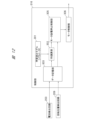
- FIG. 11 is a block diagram showing an outline of the configuration of the main parts of a control unit of a work machine according to a second modified example.
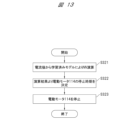
- FIG. 11 is a flowchart illustrating a processing flow for the operation of a work machine according to a second modified example.
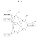
- FIG. 11 is a network configuration diagram showing the structure of a neural network of a work machine according to a second modified example.
- Figure 1 is a front view of the driving machine 100
- Figure 2 is a cross-sectional view of the driving machine 100 taken along line A-A in Figure 1.
- the driving machine 100 includes a housing section 111, an impact mechanism 112, a magazine 113, an electric motor 114, a transmission mechanism 115, a control section 116, a battery pack 117, and a counterweight section 118.
- the upper part of the paper in Figures 1 and 2 may be referred to as the top, and the lower part as the bottom.
- the left part of Figure 1 may be referred to as the right, and the right part as the left.
- the left part of Figure 2 may be referred to as the rear, and the right part as the front.
- the vertical direction toward the bottom may be referred to as the first direction
- the vertical direction toward the top may be referred to as the second direction.
- the housing section 111 is an outer element of the driver 100.
- the housing section 111 has a body section 119, a handle section 120 connected to the body section 119, and a motor case 121 connected to the body section 119.
- An attachment section 122 is connected to the handle section 120 and the motor case 121.
- the body 119 has a cylindrical shape that extends in the vertical direction.
- the body 119 contains the impact mechanism 112, the transmission mechanism 115, the counterweight 118, etc., which will be described later.
- An ejection section 123 with an ejection path 124 is provided at the tip of the body 119. That is, the ejection section 123 is fixed to the body 119.
- a fastener 125 contained in a magazine 113, which will be described later, is supplied to and supported in the ejection path 124 of this ejection section 123.
- the fastener 125 supplied to the ejection path 124 is struck by a driver blade 127, which will be described later, it is ejected toward and driven into the workpiece W1.
- the ejection section 123 supports the fastener 125 so that it can be ejected.
- An opening 139 (see Figures 3, 4, and 5) is formed on the front side of the body 119, which is used when replacing the driver blade 127 described below or when performing maintenance.
- the body 119 is provided with a cover portion 135 that covers this opening 139.
- the cover portion 135 is, for example, a resin member, and is attached so that the opening 139 can be opened and closed.
- the cover portion 135 is removably fixed to the body 119 by a fastener such as a screw.
- the handle portion 120 extends in the front-to-rear direction of the driving tool 100 at the rear of the body portion 119.
- a trigger 142 and a trigger switch 143 are provided below the handle portion 120.
- the push lever 133 provided at the bottom of the injection portion 123 descends, and when the push lever 133 abuts against the material to be driven W1, the trigger switch 143 turns on.
- the trigger switch 143 turns off.
- the motor case 121 has a cylindrical shape that extends in the front-to-rear direction of the driver 100 at the rear of the body 119.
- the motor case 121 is a housing that houses the electric motor 114, the control unit 116, etc., which will be described later.
- the mounting part 122 is disposed at the rear end of the handle part 120 and the motor case 121.
- the battery pack 117 which will be described later, is removably attached to the mounting part 122.
- a control part 116 that controls the operation of the driver 100 is provided within the mounting part 122.
- the magazine 113 is disposed below the body 119 and the motor case 121.
- the magazine 113 is a storage section that stores a plurality of fasteners 125.
- the fasteners 125 are rod-shaped, for example, including nails.
- the magazine 113 has a feeder. The feeder sends the fasteners 125 stored in the magazine 113 to the ejection path 124.
- the impact mechanism 112 is provided on both the inside and outside of the body 119.
- the impact mechanism 112 has a plunger 126 arranged inside the body 119, a driver blade 127 attached to the plunger 126, and a coil spring 136 that can expand and contract in the vertical direction.
- the coil spring 136 abuts against the plunger 126 at its end in the first direction, which is the impact direction.
- the coil spring 136 is a biasing part that applies a biasing force to the plunger 126 in the vertical downward direction (first direction).
- the plunger 126 is made of, for example, metal or synthetic resin.
- the plunger 126 is arranged on the first direction (downward) side relative to the coil spring 136.
- the plunger 126 is arranged so that it can move in the first direction by receiving a biasing force from the coil spring 136.
- the plunger 126 is also arranged so that it can move in the second direction (upward) against the biasing force of the coil spring 136 by the transmission mechanism 115 described later.
- the driver blade 127 is a member that drives in the stopper 125, and is made of, for example, metal.
- the driver blade 127 is attached to the plunger 126, and can move up and down along the injection path 124 of the injection part 123 described above.
- the driver blade 127 moves in the first direction together with the plunger 126, and strikes the stopper 125 supplied to the injection path 124.
- the plunger 126 and the driver blade 127 are movable in the first direction and in a second direction opposite to the first direction, and are an impact part that can strike the stopper 125 supported by the injection part 123 by moving in the first direction.
- the electric motor 114 has a rotor and a stator (not shown), and a motor shaft 146 is attached to the rotor.
- the motor shaft 146 is connected to an input element 148 of a reduction gear (not shown) disposed in the motor case 121.
- This reduction gear further has multiple sets of planetary gear mechanisms and an output element 149.
- the driving force generated by the rotation of the electric motor 114 i.e., the rotational force generated by the rotation of the motor shaft 146, rotates the transmission mechanism 115 (described later) via the input element 148 and the output element 149.
- the transmission mechanism 115 is disposed within the body 119 and is a rotating part that rotates upon receiving the rotational driving force of the electric motor 114. Specifically, the transmission mechanism 115 converts the rotational force of the motor shaft 146 into the operating force of the impact mechanism 112 and the operating force of the counterweight part 118. The transmission mechanism 115 biases the plunger 126 upward (second direction), which is the return direction of the coil spring 136, and biases the counterweight part 118 downward (first direction), which is the impact direction of the coil spring 136. As a result, the transmission mechanism 115 compresses the coil spring 136.
- the transmission mechanism 115 is composed of, for example, a first gear 150, a second gear 151, and a third gear 152.
- a weight bumper 137 against which the counterweight portion 118 can come into contact when released from the biasing force of the transmission mechanism 115, and a plunger bumper 138 against which the plunger 126 can come into contact are provided inside the body portion 119.
- the control unit 116 is a microcomputer having an input/output interface, a calculation processing unit, and a memory unit.
- the control unit 116 controls the driving of the electric motor 114, as will be described in detail later.
- the battery pack 117 can be detachably attached to the mounting portion 122.
- the battery pack 117 is a DC power source, and the power of the battery pack 117 can be supplied to the electric motor 114.
- the battery pack 117 is a power source unit that supplies power to the electric motor, and the electric motor 114 is driven by the power supplied from the battery pack 117.
- Figures 3, 4, and 5 are cross-sectional views of the driving machine 100 similar to those in Figure 2, but show the driving machine 100 with the cover 135 removed.
- Figure 3 shows the state in which the plunger 126 is in the standby position (first position)
- Figure 4 shows the state in which the plunger 126 is in the top dead center (second position) above the standby position
- Figure 5 shows the state in which the plunger 126 is in the bottom dead center (third position) below the standby position and the top dead center.
- the operator grasps the handle portion 120 with his/her hand, presses the tip of the injection portion 123 against the workpiece W1, and applies an operating force to the trigger 142, causing the push lever 133 to descend.
- the trigger switch 143 turns on.
- the trigger 142 and the push lever 133 function as an operating unit that is operated by the operator.
- the control unit 116 detects that the trigger switch 143 is on, it causes the battery pack 117 to supply power to the electric motor 114, causing the motor shaft 146 to rotate in the forward direction.
- the rotational force of the motor shaft 146 is amplified by a reduction gear (not shown) and transmitted to the first gear 150.
- a reduction gear (not shown)
- the first gear 150 rotates
- the second gear 151 also rotates
- the third gear 152 also rotates.
- the plunger 126 and the driver blade 127 move upward, i.e., in the second direction (rising).
- the counterweight portion 118 moves downward, i.e., in the first direction (falling).
- the plunger 126 further rises, and then the plunger 126 reaches the top dead center (see FIG. 4).
- the transmission mechanism 115 rotates, and the plunger 126 and the driver blade 127 move in the second direction against the biasing force of the coil spring 136 from the standby position to the top dead center. At this time, the coil spring 136 contracts and is in a state where maximum energy is stored.
- the driver blade 127 When the plunger 126 descends, the driver blade 127 also descends and strikes the stop 125 located in the injection path 124. As a result, the stop 125 is ejected from the ejection section 123 and driven into the workpiece W1.
- the plunger 126 stops descending when it reaches the plunger bumper 138, i.e., when it reaches the bottom dead center (see FIG. 5). That is, the plunger 126 and the driver blade 127 move in the first direction (downward) from the top dead center to the bottom dead center by the biasing force of the coil spring 136 as the plunger 126 and the transmission mechanism 115 are disengaged at the top dead center, striking the stop 125.
- the plunger 126 re-engages with the transmission mechanism 115.
- the transmission mechanism 115 is rotated by the motor shaft 146, which rotates forward together with the electric motor 114, which rotates by the power supplied from the battery pack 117. This rotation of the transmission mechanism 115 causes the plunger 126 and the driver blade 127 to rise against the biasing force of the coil spring 136.
- the control unit 116 stops the plunger 126 at a standby position on the second direction (upward) side of the bottom dead center (see FIG. 3).
- the plunger 126 and the driver blade 127 re-engage with the transmission mechanism 115 at the bottom dead center, and then the transmission mechanism 115 rotates, causing the plunger 126 and the driver blade 127 to move in the second direction (upward) to the standby position against the biasing force of the coil spring 136.
- the control unit 116 detects that the plunger 126 has reached the standby position based on the load on the electric motor 114, as described in detail below, and stops the operation of the electric motor 114. As a result, the plunger 126 and the driver blade 127 stop at the standby position as the rotation of the transmission mechanism 115 stops while they are engaged with the transmission mechanism 115 at the standby position.
- Figure 6 is a block diagram showing an outline of the main configuration of the control system of the nail driver 100.
- the nail driver 100 is equipped with a power switch circuit 200, a power supply voltage supply circuit 201, a voltage detection circuit 202, a current detection circuit 203, a trigger switch operation detection circuit 204, a push lever operation detection circuit 205, a nail remaining amount switch 207, a nail remaining amount switch operation detection circuit 208, a rotation position detection circuit 209, a rotation speed detection circuit 210, a control signal output circuit 211, an inverter circuit 212, a position detection switch 213, a position detection switch operation detection circuit 214, etc.
- the power switch circuit 200 is a circuit that switches the connection between the battery pack 117 and the power supply voltage supply circuit 201 depending on the on/off state of the trigger switch 143 and instructions from the control unit 116.
- the power supply voltage supply circuit 201 is a constant voltage circuit that supplies the driving power of the battery pack 117 to each part of the driving machine 100 when the power switch circuit 200 is turned on.
- the voltage detection circuit 202 detects the voltage of the battery pack 117 and outputs a signal indicating the detected voltage to the control unit 116.
- the current detection circuit 203 detects the current value of the driving current supplied from the battery pack 117 to the electric motor 114 via the inverter circuit 212, and outputs a signal indicating the detected current value to the control unit 116.
- the trigger switch operation detection circuit 204 detects the operation of the trigger 142 by the operator and outputs a signal (operation signal) to the control unit 116.
- the push lever operation detection circuit 205 detects that the push lever 133 has come into contact with the workpiece W1 and outputs a signal to the control unit 116.
- the nail remaining amount switch 207 is provided to engage with a feeding member such as a feeder at the end of the magazine 113 on the ejection section 123 side, and detects the remaining amount (e.g., 0 to 5 nails remaining) of fasteners 125 (connected nails) loaded in the magazine 113.
- the nail remaining amount switch operation detection circuit 208 detects the output of the nail remaining amount switch 207 and outputs a signal indicating the detection result to the control unit 116.
- the rotational position detection circuit 209 is, for example, a Hall IC, which detects the position of the rotor and motor shaft 146 of the electric motor 114 in the rotational direction and outputs a signal indicating the rotational position to the control unit 116 and the rotation speed detection circuit 210.
- the rotation speed detection circuit 210 detects the rotation speed of the electric motor 114 based on the number of signals output from the rotational position detection circuit 209 counted within a unit time and outputs it to the control unit 116.
- the inverter circuit 212 is provided in the electric circuit between the stator of the electric motor 114 and the battery pack 117.
- the control signal output circuit 211 is controlled by the control unit 116 and outputs signals that turn on and off the switching elements of the inverter circuit 212 individually.
- the position detection switch 213 is a switch operated by the counterweight portion 118, which moves in conjunction with the plunger 126.
- the position detection switch 213 is turned on when the counterweight portion 118, which has risen to the top dead center, comes into contact with it.
- the position detection switch operation detection circuit 214 detects that the position detection switch 213 has been turned on, and outputs a signal to the control unit 116.
- control unit 116 detects the load on the electric motor 114, and controls the operation of the electric motor 114 based on the detected load (operation control), determines the operation of the impact mechanism 112 (operation process determination), and determines whether there is an abnormality in the operation of the impact mechanism 112 (abnormality determination).
- control unit 116 determines based on the detected load that the plunger 126 has reached the standby position after the fastener 125 has been driven in, it stops the operation of the electric motor 114.
- the control unit 116 detects the load by detecting the drive current of the electric motor 114, which is driven by power supplied by the battery pack 117. In other words, the control unit 116 stops the operation of the electric motor 114 based on the current value detected by the current detection circuit 203.
- the control unit 116 detects the drive current of the electric motor 114, for example, every 100 ⁇ s, and converts the 10 current values detected every 100 ⁇ s into a 1 ms current value. Specifically, the control unit 116 adopts the maximum value of the total of 10 current values detected every 100 ⁇ s as the 1 ms current value.
- the adopted current value is stored in a storage medium such as a memory in the control unit 116.
- Figure 7 is a diagram showing the current value detected when the plunger 126 moves from the standby position to the top dead center, the bottom dead center, and then back to the standby position.
- the vertical axis represents the current value
- the horizontal axis represents time.
- Figure 7 shows the case where the trigger switch 143 is turned on at time 0 ms.
- the electric motor 114 starts to rotate due to the power supplied from the battery pack 117 as described above.
- the plunger 126 is stopped in the standby position (first position) and is biased downward (in the first direction) by the coil spring 136, so a large load is applied when the electric motor 114 starts to rotate, and the starting power (current) becomes large.
- the detected current value increases.
- time t1 when the plunger 126 starts to rise and the influence of the starting power becomes low, the increase in the detected current value is suppressed, and the current value then remains at an approximately constant value.
- the plunger 126 When the plunger 126 reaches the top dead center (second position) and then disengages from the third gear 152 and the coil spring 136 is released, the plunger 126 starts to descend (time t2). When the plunger 126 descends, the load from the plunger 126 is no longer applied to the transmission mechanism 115, so the electric motor 114 rotates with a small load and the detected current value decreases rapidly. The current value decreases until the plunger 126 reaches the bottom dead center (third position) (time t5).
- the control unit 116 stops the rotation of the electric motor 114 after a predetermined standby time has elapsed.
- the standby time can be considered to be the delay time between when the current value becomes equal to or greater than the first threshold value th1 described below and when the control unit 116 stops the electric motor 114.
- the control unit 116 uses the current value detected by the current detection circuit 203 to raise the plunger 126 that has reached the bottom dead center to the standby position (pre-winding) and stop it. Specifically, the control unit 116 uses a first threshold value th1 and a second threshold value th2 to compare the detected current value. The first threshold value th1 is used to determine whether the plunger 126 has reached the vicinity of the standby position due to pre-winding. Specifically, the control unit 116 determines that the plunger 126 has reached the vicinity of the standby position due to pre-winding when the state in which the detected current value is equal to or greater than the first threshold value th1 has elapsed for a first determination time (e.g., 5 ms) or more.
- a first determination time e.g., 5 ms
- control unit 116 detects that the current value has become equal to or greater than the first threshold value th1 at time t6, and determines that the plunger 126 has reached the vicinity of the standby position when the state in which the current value is equal to or greater than the first threshold value th1 continues until time t7 when the first determination time has elapsed.
- the second threshold th2 is used to determine whether or not preliminary winding is possible after the plunger 126, which has reached the top dead center, descends toward the bottom dead center. Specifically, the control unit 116 determines that preliminary winding of the plunger 126 is possible when the state in which the detected current value is equal to or less than the second threshold th2 has elapsed for a second determination time (e.g., 10 ms) or more. That is, the control unit 116 detects that the current value has become equal to or less than the second threshold th2 at time t3, and determines that preliminary winding is possible when the current value remains equal to or less than the second threshold th2 until time t5, when the second determination time has elapsed.
- the first threshold th1 and the second threshold th2 may be the same value or different values.
- the control unit 116 changes the standby time when stopping the rotation of the electric motor 114 (i.e., the delay time after the current value becomes equal to or greater than the first threshold value th1) according to the voltage of the battery pack 117. In this case, the control unit 116 lengthens the standby time when the voltage value of the battery pack 117 detected by the voltage detection circuit 202 becomes smaller than a preset value.
- control unit 116 detects the voltage value of the battery pack 117 before the plunger 126 starts to rise (start) from the standby position, that is, before the electric motor 114 starts to rotate.
- the control unit 116 lengthens the standby time by 1 ms every time the detected voltage value becomes 0.4 V lower than the preset value. Additionally, the control unit 116 may linearly increase the standby time in response to a decrease in the detected voltage value.
- control unit 116 The process steps performed by the control unit 116 in the operation control will be described with reference to the flowchart shown in FIG. 8.
- the process steps shown in FIG. 8 are performed by the control unit 116 reading a program stored in the storage unit and executing the program.
- step S10 the control unit 116 determines whether the current value detected by the current detection circuit 203 is equal to or less than the second threshold value th2. If the current value is equal to or less than the second threshold value th2, the control unit 116 makes a positive determination and the process proceeds to step S11. If the current value is greater than the second threshold value th2, the control unit 116 makes a negative determination and the process of step S10 is repeated.
- step S11 the control unit 116 determines whether or not the second determination time of 10 ms has elapsed. If the second determination time has elapsed, the control unit 116 makes a positive determination. The control unit 116 then determines that pre-winding of the plunger 126 is possible. Processing then proceeds to step S12. If the second determination time has not elapsed, the control unit 116 makes a negative determination, and processing returns to step S10.
- step S12 the control unit 116 obtains the current value, which is the load of the electric motor 114 performing the preliminary winding, from the current detection circuit 203, and determines whether the current value is equal to or greater than the first threshold value th1. If the current value is equal to or greater than the first threshold value th1, the control unit 116 makes a positive determination and the process proceeds to step S13. If the current value is less than the first threshold value th1, the control unit 116 makes a negative determination and the process of step S12 is repeated.
- step S13 the control unit 116 determines whether or not the first determination time of 5 ms has elapsed. If the first determination time has elapsed, the control unit 116 makes a positive determination, and the process proceeds to step S14. If the first determination time has not elapsed, the control unit 116 makes a negative determination, and the process returns to step S12.
- step S14 it is determined whether the waiting time has elapsed. If the waiting time has elapsed, the control unit 116 makes a positive determination, and the process proceeds to step S15. If the waiting time has not elapsed, the control unit 116 makes a negative determination, and the process of step S14 is repeated. In step S15, the control unit 116 stops the electric motor 114 and ends the process.
- control unit 116 determines the operation step of the plunger 126 and the driver blade 127 based on the amount of change in the detected load. In this case, the control unit 116 also detects the load by detecting the drive current of the electric motor 114, which is driven by the power supplied by the battery pack 117. In other words, the control unit 116 determines the operation step of the plunger 126 and the driver blade 127 based on the amount of change in the current value detected by the current detection circuit 203.
- control unit 116 detects the drive current of the electric motor 114, for example, every 100 ⁇ s, and converts the 10 current values detected every 100 ⁇ s into a current value for 1 ms. The control unit 116 then calculates the difference (differential current value) between a certain current value and the current value converted from that current value 10 ms earlier, a predetermined time interval, as the amount of change in the current value. The control unit 116 determines the operating process of the plunger 126 and the driver blade 127 based on the change in the differential current value obtained at each of the above-mentioned time intervals.
- Figure 9 is a diagram showing the change in the differential current value when the plunger 126 moves from the standby position to the top dead center, the bottom dead center, and then back to the standby position.
- the vertical axis represents the differential current value
- the horizontal axis represents time.
- Figure 9 shows the case where the trigger switch 143 is turned on at time 0 ms.
- the starting power (current) is large immediately after the electric motor 114 starts to rotate. Therefore, at time t10, the differential current value increases sharply. Then, when the plunger 126 starts to rise, the influence of the starting power (current) decreases, and the differential current value decreases. Therefore, at time t10, the differential current value becomes a maximum value (up-peak). At time t10 when this up-peak is detected, the control unit 116 determines that the plunger 126 has started to rise (start) as an operating process.
- the plunger 126 After the plunger 126 reaches the top dead center at time t12, the plunger 126 disengages from the transmission mechanism 115 and starts to descend, and the differential current value starts to increase. Therefore, at time t12, the differential current value becomes a minimum value (down peak). At time t12 when this down peak is detected, the control unit 116 determines that the start of the plunger 126 is complete as an operating process.
- the control unit 116 detects that the differential current value decreases for a predetermined time (e.g., 5 ms) or more after the acceleration increase is determined, then increases once, and then increases again for a predetermined time (e.g., 5 ms) or more, the control unit 116 determines that the striking process in which the driver blade 127 strikes the stopper 125 is the operation process.
- the differential current value decreases from time t11 to time t12, increases from time t12 to time t13, and decreases from time t13 to time t14. Therefore, the control unit 116 determines that the driver blade 127 strikes the stopper 125 and the stopper 125 is ejected.
- control unit 116 The processes performed by the control unit 116 in the operation determination will be described with reference to the flowchart shown in FIG. 10. Each process shown in FIG. 10 is performed by the control unit 116 reading a program stored in the storage unit and executing the program.
- step S20 the control unit 116 detects a steep increase in the calculated differential current value.
- step S21 the control unit 116 determines whether or not an up-peak has occurred in the change in the differential current value. If an up-peak has occurred in the change in the differential current value, the control unit 116 makes a positive determination. At this time, the control unit 116 determines the start of the plunger 126 as an operating step. The process then proceeds to step S22. If an up-peak has not occurred, the control unit 116 makes a negative determination, and the process of step S21 is repeated.
- step S22 the control unit 116 determines whether or not a zero cross has occurred in the change in the calculated differential current value. If a zero cross has occurred in the change in the differential current value, the control unit 116 makes a positive determination. At this time, the control unit 116 determines that the plunger 126 is accelerating upward as an operating step. The process then proceeds to step S23. If a zero cross has not occurred in the change in the differential current value, the control unit 116 makes a negative determination, and the process of step S22 is repeated.
- step S23 the control unit 116 determines whether a down-peak has occurred in the change in the calculated differential current value. If a down-peak has occurred in the change in the differential current value, the control unit 116 makes a positive determination. At this time, the control unit 116 determines that the start of the plunger 126 has been completed as an operation step. Thereafter, the process proceeds to step S24. If a down-peak has not occurred in the change in the differential current value, the control unit 116 makes a negative determination, and the process of step S23 is repeated.
- step S24 the control unit 116 determines whether the change in the calculated differential current value increases once and then decreases, i.e., whether a peak occurs again due to an increase or decrease in the change in the differential current value after a down-peak. If a peak occurs in the change in the differential current value by increasing after a down-peak and then decreasing again, the control unit 116 makes a positive determination. At this time, the control unit 116 determines that the operation process is the striking process in which the driver blade 127 strikes the stopper 125. The process then proceeds to step S25. If a peak does not occur in the change in the differential current value after the down-peak, the control unit 116 makes a negative determination, and the process of step S24 is repeated.
- step S25 the control unit 116 determines whether or not a zero cross has occurred in the change in the calculated differential current value. If a zero cross has occurred in the change in the differential current value, the control unit 116 makes a positive determination. At this time, the control unit 116 determines that the preliminary winding of the plunger 126 has started as an operating process. Thereafter, the process proceeds to step S26. If a zero cross has not occurred in the change in the differential current value, the control unit 116 makes a negative determination, and the process of step S25 is repeated. In step S26, the control unit 116 determines that the preliminary winding of the plunger 126 is in progress as an operating process based on the calculated differential current value, and ends the process when the plunger 126 reaches the standby position.
- the control unit 116 determines whether or not an abnormality has occurred in the operation process of the impact mechanism 112 based on the detected load or change in load. Specifically, the control unit 116 determines whether or not an abnormality has occurred based on the change in the current value detected during operation control or the differential current value detected during operation determination. Specifically, the control unit 116 determines that an abnormality has occurred in the movement of the impact mechanism 112 when the current value becomes equal to or less than the second threshold value th2 after a predetermined response error timing.
- control unit 116 determines whether or not an abnormality has occurred in the movement of the plunger 126 and the driver blade 127 based on the time from when the operator performs an operation until the detected current value becomes equal to or less than the second threshold value th2. In addition, the control unit 116 determines that an abnormality has occurred in the movement of the impact mechanism 112 when the current value becomes equal to or more than the first threshold value th1 after a predetermined timeout error timing. In other words, the control unit 116 determines whether there is an abnormality in the movement of the plunger 126 and the driver blade 127 based on the time from when the operator performs the operation until the detected current value becomes equal to or greater than the first threshold value th1.
- the control unit 116 determines that an abnormality has occurred in the drive of the impact mechanism 112 when a waveform different from the waveform showing the change in the differential current value shown in FIG. 9 is detected. In other words, the control unit 116 determines whether the movement of the plunger 126 and the driver blade 127 has been performed normally based on the change in the differential current value, which is the amount of change in current at each predetermined time interval. For example, the control unit 116 determines that an abnormality has occurred in the movement of the plunger 126 and the driver blade 127 when the above-mentioned impact process is not determined until the detected current value becomes equal to or greater than the first threshold value th1.
- control unit 116 determines that an abnormality has occurred in the movement of the plunger 126 and the driver blade 127 when the impact process is not determined between the time the operator performs the operation and the time the electric motor 114 is stopped based on the load and the plunger 126 and the driver blade 127 are stopped at the standby position.
- the control unit 116 performs the abnormality determination after the current value becomes equal to or greater than the first threshold value th1 and the plunger 126 is stopped.
- Figures 11 (A) to (D) are diagrams showing the waveforms of the current values detected when the plunger 126, which is not in the standby position, moves, with the vertical axis representing the differential current value and the horizontal axis representing time. Note that in Figures 11 (A) to (D), 100 ms is the timing for determining a response error, and 300 ms is the timing for determining a timeout error.
- Figure 11 (A) shows the waveform of the current value when the plunger 126, which was located at the bottom dead center, starts due to a factor such as a voltage drop in the battery pack 117.
- the plunger 126 starts starting from the bottom dead center, so it starts descending without reaching the top dead center.
- the detected current value is equal to or less than the second threshold value th2 at time t20 before the response error.
- the plunger 126 stops at the standby position.
- the control unit 116 determines that an abnormality has occurred.
- control unit 116 warns the operator that an abnormality has occurred using, for example, a warning unit such as a warning lamp (not shown). Then, the control unit 116 prevents the driving machine 100 from operating, such as by not driving the electric motor 114.
- a warning unit such as a warning lamp (not shown).
- Figure 11 (B) shows the waveform of the current value when the plunger 126, which was located above the bottom dead center, starts to start.
- the plunger 126 starts to descend without reaching the top dead center.
- the detected current value becomes equal to or less than the second threshold value th2 at time t21 before the response error.
- the plunger 126 stops at the standby position.
- the time required for the plunger 126 to stop at the standby position is shorter than in the case shown in Figure 11 (A).
- control unit 116 determines that an abnormality has occurred if the impact process has not been determined based on the change in the differential current value. In this case, the control unit 116 warns the operator that an abnormality has occurred, for example, by turning on a warning lamp (not shown). The control unit 116 then prevents the driver 100 from operating, for example by not driving the electric motor 114.
- Figure 11 (C) shows the waveform of the current value when the plunger 126 starts to move, which is located above the position where the plunger 126 stopped in Figure 11 (B) and below the standby position. Also, the control unit 116 is assumed to determine the impact process based on the change in the differential current value. In this case, the plunger 126 starts to move down after reaching the top dead center, since it starts to move up from near the standby position.
- the detected current value becomes equal to or less than the second threshold value th2 at time t22 after the response error.
- the detected current value becomes equal to or greater than the first threshold value th1 at time t23 after the timeout error.
- the control unit 116 determines that an abnormality has occurred and stops driving the electric motor 114.
- Figure 11 (D) shows the waveform of the current value when the plunger 126, which was located near the top dead center, begins to start. It is also assumed that the control unit 116 determines the impact process based on the change in the differential current value. In this case, the plunger 126 starts from near the standby position, so it begins to descend after reaching the top dead center. As shown in the figure, the detected current value is equal to or less than the second threshold value th2 at time t24 before the response error. Then, when the current value becomes equal to or greater than the first threshold value th1, the plunger 126 stops. In this case, the control unit 116 determines that there is no abnormality in the plunger 126.
- the control unit 116 can detect the load of the electric motor 114.
- the control unit 116 stops the electric motor 114 based on the detected load, thereby stopping the plunger 126 and the driver blade 127, which move in the vertical direction by the driving force of the electric motor 114 and the biasing force of the coil spring 136, at the standby position. This makes it possible to determine that the plunger 126 has reached the standby position based on the load of the electric motor 114, so that the plunger 126 and the driver blade 127 can be stopped at the standby position with high accuracy.
- the variation in the time from when the trigger 142 and the push lever 133 are turned on and the electric motor 114 starts driving to when the fastener 125 is driven is reduced, which contributes to improving the workability of the worker using the driving machine 100.
- a position detection switch such as the position detection switch 213
- the position detection switch 213 may be eliminated, which reduces the number of parts and makes it possible to make the driver 100 lighter and smaller.
- the control unit 116 detects the drive current of the electric motor 114 as the load of the electric motor 114. This makes it possible to detect the load of the electric motor 114 with a simple configuration.
- the control unit 116 stops the electric motor 114. This makes it possible to detect that the electric motor 114 has reached the vicinity of the standby position, thereby enabling the plunger 126 to be stopped at the standby position with high accuracy.
- the control unit 116 stops the electric motor 114. This makes it possible to determine that the plunger 126 has risen and reached the standby position after the stopper 125 has been ejected. As a result, erroneous determination of the position of the plunger 126 is suppressed, and the accuracy of position detection when stopping the plunger at the standby position can be improved.
- the control unit 116 stops the electric motor 114 after a predetermined delay time has elapsed since the detected current value became equal to or greater than the first threshold value th1, i.e., after the first discrimination time has elapsed and the standby time has elapsed. This makes it possible to raise the plunger 126, which has risen close to the standby position, to the standby position and stop it there.
- the control unit 116 changes the standby time based on the voltage value of the battery pack 117. This makes it possible to extend the time during which the plunger 126 can rise even when the rotation speed of the electric motor 114 decreases and the inertia becomes low due to a decrease in the remaining battery charge of the battery pack 117. As a result, it is possible to prevent the occurrence of a malfunction in which the preliminary winding ends before the plunger 126 reaches the standby position.
- the control unit 116 determines whether or not there is an abnormality in the movement of the plunger 126 and the driver blade 127 based on the time from when the operator performs an operation until the detected current value becomes equal to or less than the second threshold value th2. This allows the presence or absence of an abnormality to be determined based on the time at which a characteristic point in the change in the current value appears, making it possible to determine whether or not the stopper 125 has been ejected using a simple configuration.
- the control unit 116 determines whether or not there is an abnormality in the movement of the plunger 126 and the driver blade 127 based on the time from when the operator performs an operation until the detected current value becomes equal to or greater than the first threshold value th1. This makes it possible to determine whether or not there is an abnormality based on whether or not the plunger 126 reaches the standby position by the time set as the timeout error.
- the control unit 116 determines whether the movement of the plunger 126 and the driver blade 127 is normal or not based on the amount of change in the load at each predetermined time interval, i.e., the differential current value which is the amount of change in the current. This makes it possible to determine whether there is an abnormality in the movement of the plunger 126 and the driver blade 127 with a simple configuration.
- the control unit 116 determines the operation process of the plunger 126 and the driver blade 127 based on the amount of change in the load at each predetermined time interval, i.e., the differential current value, which is the amount of change in the current. This makes it possible to determine what operation the plunger 126 and the driver blade 127 have performed with a simple configuration.
- the control unit 116 can determine that the striking process in which the driver blade 127 strikes the stopper 125 is an operation process.
- the control unit 116 determines that there is an abnormality in the movement of the plunger 126 and the driver blade 127. This makes it possible to detect the current value of the electric motor 114 with a simple configuration, and to determine that there is an abnormality in the movement of the plunger 126 and the driver blade 127 based on the detected current value and the differential current value.
- the control unit 116 determines that the driver blade 127 has struck the stopper 125 and the stopper 125 has been ejected. This makes it possible to determine, with a simple configuration, whether or not the stopper 125 has been ejected based on the change in the load on the electric motor 114.
- the control unit 116 is not limited to detecting the drive current as the load of the electric motor 114, and may detect the rotation speed of the electric motor 114. In this case, the control unit 116 detects the rotation speed of the electric motor 114 based on a signal output from the rotation speed detection circuit 210. Then, based on the increase or decrease in the detected rotation speed, the control unit 116 determines whether or not the plunger 126 has been pre-wound after the stopper 125 is ejected and has reached the standby position. Specifically, the control unit 116 stores in advance the rotation speed of the electric motor 114 when the standby position is reached by pre-wounding as a threshold value, and stops the rotation of the electric motor 114 when the detected rotation speed becomes smaller than this threshold value.
- the first threshold th1 or the second threshold th2 may be a variable value.
- the control unit 116 may change the value of the first threshold th1 according to the remaining battery charge of the battery pack 117.
- the control unit 116 detects the remaining battery charge of the battery pack 117 based on the voltage value of the battery pack 117 detected by the voltage detection circuit 202 when the plunger 126 is started.
- the control unit 116 may calculate (detect) the remaining battery charge of the battery pack 117 based on the current value detected when the plunger 126 is started.
- the control unit 116 increases the value of the first threshold th1.
- the control unit 116 may increase the value of the first threshold th1 linearly or nonlinearly (e.g., stepwise) according to the decrease in the detected voltage value.
- control unit 116 may change the first threshold th1 or the second threshold th2 according to the number of times the fasteners 125 have been ejected (the number of driving operations).
- the control unit 116 can calculate the number of fasteners 125 used, i.e., the number of driving operations, based on the signal output from the nail remaining amount switch operation detection circuit 208, and increase the value of the first threshold th1 according to an increase in the number of driving operations.
- the control unit 116 may vary the first threshold value th1 or the second threshold value th2 based on the deterioration of the coil spring 136. In this case, the control unit 116 determines the degree of deterioration of the coil spring 136 based on the value of the starting current of the electric motor 114. For example, if the coil spring 136 has become soft due to deterioration, the control unit 116 may reduce the first threshold value th1. Also, if the coil spring 136 has become hard due to deterioration, the control unit 116 may increase the first threshold value th1.
- the control unit 116 may vary the first threshold value th1 or the second threshold value th2 based on the change in air pressure in the accumulator chamber. In this case, too, the control unit 116 determines the change in air pressure in the accumulator chamber based on the value of the starting current of the electric motor 114. For example, if compressed air is leaking from the accumulator chamber and the air pressure is decreasing, the control unit 116 may decrease the first threshold value th1. Also, if the air pressure in the accumulator chamber is increasing, such as when the outside temperature is high, the control unit 116 may increase the first threshold value th1.
- the control unit 116 is not limited to determining whether the plunger 126 has reached the standby position based on the detected current value and the first threshold value th1.
- the control unit 116 may learn the waveform of the detected current value as teacher data and use the waveform of the detected current value to determine whether the plunger 126 has reached the standby position based on the learning result.
- the control unit 116 may perform control to gradually reduce the ascending speed of the plunger 126 when stopping the plunger 126 at the standby position.
- multiple thresholds smaller than the first threshold th1 are set in advance, and the control unit 116 may reduce the number of rotations of the electric motor 114 by a predetermined rate each time the detected current value exceeds these multiple thresholds.
- the control unit 116 may perform control to stop the plunger 126 at the bottom dead center.
- a threshold value corresponding to the current value at time t5 shown in FIG. 7 is set, and when the control unit 116 determines that the detected current value has reached this threshold value, it may stop driving the electric motor 114.
- the driving machine 100 which is a work machine of variation 2, uses artificial intelligence (AI) to determine when to stop the electric motor 114 in order to stop the plunger 126 at the standby position.
- AI artificial intelligence
- the current value is machine-learned by the artificial intelligence in advance, and the time to stop the electric motor 114 is determined based on the data obtained by the machine learning (learning model).
- variation 2 uses a neural network (hereinafter also referred to as "NN”) to perform control by the control unit 316.
- NN neural network
- Figure 12 is a block diagram showing the main components of the control unit 316 of the driving machine 100 according to the second modified example.
- the control unit 316 of the second modified example replaces the control unit 116 of the embodiment described above.
- the trained model 301 is an example of a trained model, and is data used when determining the timing to stop the electric motor 114 based on changes in the current value.
- the NN calculation unit 302 is an example of a calculation unit, and is a calculation circuit that controls the current supply pattern to the stator according to the timing to stop the electric motor 114 determined based on the trained model 301.
- FIG. 13 is a flow chart showing the start and stop of the electric motor 114 in the driving machine 100 according to the second modified example.
- the control unit 316 performs an NN calculation using the trained model 301 based on the changes in the current value data and the rotor position data stored in the data storage unit 303, and in step S322, it determines (estimates) the time to stop the electric motor 114 based on the results of the NN calculation.
- the electric motor 114 is stopped at the determined time to stop the electric motor 114, and the process ends.
- Figure 14 is a network configuration diagram showing the structure of the neural network of the driving machine 100 according to the second modification.
- the NN calculation unit 302 determines the stop time of the electric motor 114 by using an NN with a predetermined number of sampled current values as input data 310 and the stop time of the electric motor 114 as output data 313.
- Information regarding the stop time of the electric motor 114 is input to the motor discharge stop control unit 305 (see Figure 12), which sends a signal to the motor control unit 306 (see Figure 12) based on the information regarding the stop time of the electric motor 114.
- the motor control unit 306 controls the control signal output circuit 211 based on the signal sent from the motor discharge stop control unit 305, and stops the electric motor 114 at the appropriate time.
- the driving machine 100 can accurately determine the time to stop the electric motor 114 even when the waveform of the current value is complex and it is difficult to detect the inflection point, so that the driving machine 100 can be provided at low cost.
- the input data 310 of the NN calculation unit 302 may also include other information such as the voltage value of the battery pack 117, which allows the time to stop the electric motor 114 to be determined even more accurately.
Landscapes
- Engineering & Computer Science (AREA)
- Mechanical Engineering (AREA)
- Life Sciences & Earth Sciences (AREA)
- Forests & Forestry (AREA)
- Portable Nailing Machines And Staplers (AREA)
Priority Applications (1)
| Application Number | Priority Date | Filing Date | Title |
|---|---|---|---|
| JP2025503844A JPWO2024181313A1 (https=) | 2023-02-28 | 2024-02-22 |
Applications Claiming Priority (2)
| Application Number | Priority Date | Filing Date | Title |
|---|---|---|---|
| JP2023029666 | 2023-02-28 | ||
| JP2023-029666 | 2023-02-28 |
Publications (1)
| Publication Number | Publication Date |
|---|---|
| WO2024181313A1 true WO2024181313A1 (ja) | 2024-09-06 |
Family
ID=92590532
Family Applications (1)
| Application Number | Title | Priority Date | Filing Date |
|---|---|---|---|
| PCT/JP2024/006592 Ceased WO2024181313A1 (ja) | 2023-02-28 | 2024-02-22 | 作業機 |
Country Status (2)
| Country | Link |
|---|---|
| JP (1) | JPWO2024181313A1 (https=) |
| WO (1) | WO2024181313A1 (https=) |
Citations (4)
| Publication number | Priority date | Publication date | Assignee | Title |
|---|---|---|---|---|
| JP2015030052A (ja) * | 2013-07-31 | 2015-02-16 | 日立工機株式会社 | 留め具打込機 |
| JP2017170530A (ja) * | 2016-03-18 | 2017-09-28 | 日立工機株式会社 | 打込機 |
| JP2017213666A (ja) * | 2016-06-02 | 2017-12-07 | 日立工機株式会社 | 打込機 |
| JP2022173772A (ja) * | 2021-05-10 | 2022-11-22 | マックス株式会社 | 打込工具 |
-
2024
- 2024-02-22 WO PCT/JP2024/006592 patent/WO2024181313A1/ja not_active Ceased
- 2024-02-22 JP JP2025503844A patent/JPWO2024181313A1/ja active Pending
Patent Citations (4)
| Publication number | Priority date | Publication date | Assignee | Title |
|---|---|---|---|---|
| JP2015030052A (ja) * | 2013-07-31 | 2015-02-16 | 日立工機株式会社 | 留め具打込機 |
| JP2017170530A (ja) * | 2016-03-18 | 2017-09-28 | 日立工機株式会社 | 打込機 |
| JP2017213666A (ja) * | 2016-06-02 | 2017-12-07 | 日立工機株式会社 | 打込機 |
| JP2022173772A (ja) * | 2021-05-10 | 2022-11-22 | マックス株式会社 | 打込工具 |
Also Published As
| Publication number | Publication date |
|---|---|
| JPWO2024181313A1 (https=) | 2024-09-06 |
Similar Documents
| Publication | Publication Date | Title |
|---|---|---|
| TWI781941B (zh) | 釘打機 | |
| JP6690710B2 (ja) | 打込機 | |
| US20170217004A1 (en) | Fastener driving tool | |
| JP5424105B2 (ja) | 電動式打込機 | |
| EP3156180B1 (en) | Fastener driving machine | |
| US10442066B2 (en) | Driver | |
| US20230137720A1 (en) | Working tool | |
| WO2018198672A1 (ja) | 打込機 | |
| US20090255972A1 (en) | Electric driving machine | |
| WO2016199670A1 (ja) | 打込機 | |
| JP2014172163A (ja) | 電動工具 | |
| JP7205617B2 (ja) | 打込機 | |
| CN111315537B (zh) | 打入机 | |
| WO2024181313A1 (ja) | 作業機 | |
| JP6689087B2 (ja) | 打ち込み工具 | |
| JP5288322B2 (ja) | 打込機 | |
| CN120112386A (zh) | 作业机 | |
| JP7099138B2 (ja) | 打込機 | |
| WO2021106497A1 (ja) | 打込機 | |
| JP6656941B2 (ja) | 打ち込み工具 | |
| JP2018051724A (ja) | 打込機 | |
| EP4347190B1 (en) | Flywheel driven fastening tool having at least two timeout periods for determining when to stop driving flywheel | |
| EP3785859A1 (en) | Driving machine | |
| JP6972981B2 (ja) | 打込機 | |
| JP6790629B2 (ja) | 打込機 |
Legal Events
| Date | Code | Title | Description |
|---|---|---|---|
| 121 | Ep: the epo has been informed by wipo that ep was designated in this application |
Ref document number: 24763793 Country of ref document: EP Kind code of ref document: A1 |
|
| ENP | Entry into the national phase |
Ref document number: 2025503844 Country of ref document: JP Kind code of ref document: A |
|
| WWE | Wipo information: entry into national phase |
Ref document number: 2025503844 Country of ref document: JP |
|
| NENP | Non-entry into the national phase |
Ref country code: DE |
|
| 122 | Ep: pct application non-entry in european phase |
Ref document number: 24763793 Country of ref document: EP Kind code of ref document: A1 |