WO2024180943A1 - 音叉型駆動素子、光偏向素子および駆動装置 - Google Patents
音叉型駆動素子、光偏向素子および駆動装置 Download PDFInfo
- Publication number
- WO2024180943A1 WO2024180943A1 PCT/JP2024/001719 JP2024001719W WO2024180943A1 WO 2024180943 A1 WO2024180943 A1 WO 2024180943A1 JP 2024001719 W JP2024001719 W JP 2024001719W WO 2024180943 A1 WO2024180943 A1 WO 2024180943A1
- Authority
- WO
- WIPO (PCT)
- Prior art keywords
- tuning fork
- fork type
- driving element
- unit
- type driving
- Prior art date
- Legal status (The legal status is an assumption and is not a legal conclusion. Google has not performed a legal analysis and makes no representation as to the accuracy of the status listed.)
- Ceased
Links
Images








Classifications
-
- B—PERFORMING OPERATIONS; TRANSPORTING
- B81—MICROSTRUCTURAL TECHNOLOGY
- B81B—MICROSTRUCTURAL DEVICES OR SYSTEMS, e.g. MICROMECHANICAL DEVICES
- B81B3/00—Devices comprising flexible or deformable elements, e.g. comprising elastic tongues or membranes
-
- G—PHYSICS
- G02—OPTICS
- G02B—OPTICAL ELEMENTS, SYSTEMS OR APPARATUS
- G02B26/00—Optical devices or arrangements for the control of light using movable or deformable optical elements
- G02B26/08—Optical devices or arrangements for the control of light using movable or deformable optical elements for controlling the direction of light
-
- G—PHYSICS
- G02—OPTICS
- G02B—OPTICAL ELEMENTS, SYSTEMS OR APPARATUS
- G02B26/00—Optical devices or arrangements for the control of light using movable or deformable optical elements
- G02B26/08—Optical devices or arrangements for the control of light using movable or deformable optical elements for controlling the direction of light
- G02B26/10—Scanning systems
Definitions
- the present invention relates to a tuning fork type drive element that rotates a movable part about a rotation axis, an optical deflection element equipped with the tuning fork type drive element, and a drive device equipped with the tuning fork type drive element.
- drive elements that rotate a movable part using MEMS (Micro Electro Mechanical System) technology have been developed.
- MEMS Micro Electro Mechanical System
- a reflective surface is placed on the movable part, and the light incident on the reflective surface can be scanned at a predetermined deflection angle.
- This type of drive element is mounted, for example, on image display devices such as head-up displays and head-mounted displays.
- This type of drive element can also be used in laser radars that use laser light to detect objects.
- Patent Document 1 describes a tuning fork type driving element that rotates a movable part by a so-called tuning fork vibrator.
- the movable part is connected to the tuning fork vibrator by a first connector that extends along the rotation axis.
- the tuning fork vibrator is also connected perpendicularly to a second connector that extends along the rotation axis.
- the second connector is connected to a base.
- the base forms a fixing part for fixing the driving element to the installation surface.
- asymmetry may occur in the processed shape during the manufacturing process.
- unwanted vibrations different from the original intended vibrations are generated in the tuning fork type driving element, resulting in reduced performance such as reduced driving efficiency.
- the present invention aims to provide a tuning fork type driving element, an optical deflection element, and a driving device that can smoothly detect unwanted vibrations other than proper vibrations.
- the tuning fork type driving element comprises a movable part that can rotate about a rotation axis, a connecting part that extends from the movable part along the rotation axis, a pair of arms arranged on either side of the rotation axis, a support part that connects the connecting part and the pair of arms to a fixed part, a first driving part arranged on each of the arms that rotates the movable part, a first sensor part for detecting the rotation of the movable part, and a second sensor part for detecting unwanted vibrations generated in the movable part.
- asymmetry may occur in the processed shape during the manufacturing process.
- unwanted vibrations different from the originally intended vibrations occur in the tuning fork type driving element, resulting in performance degradation such as a decrease in driving efficiency.
- the tuning fork type driving element of this embodiment it is possible to detect the occurrence of unwanted vibrations other than proper rotation in the moving part based on the detection signal of the second sensor unit. Therefore, even if unwanted vibrations occur in the moving part due to asymmetry in the processed shape of the tuning fork type driving element, the unwanted vibrations can be smoothly grasped. This makes it possible to proceed with measures to make the moving part vibrate properly, such as performing processing to eliminate the asymmetry.
- the optical deflection element according to the second aspect of the present invention comprises the tuning fork type driving element according to the first aspect and a reflecting surface disposed on the movable part.
- the optical deflection element includes the tuning fork type driving element of the first embodiment, so that it is possible to smoothly grasp the occurrence of unwanted vibrations on the reflective surface. This allows measures to be taken to properly vibrate the reflective surface, and the light incident on the reflective surface can be stably deflected in accordance with the vibration of the movable part.
- the driving device includes the tuning fork type driving element according to the first aspect.
- the second sensor unit includes a pair of sensors arranged on the arm section, sandwiching the first driving unit in the width direction of the arm section, and each of the pair of sensors outputs a signal corresponding to distortion.
- the tuning fork type driving element further includes a pair of second driving units arranged on the arm section, sandwiching the first driving unit in the width direction of the arm section.
- the driving device includes a control unit that drives the second driving units to suppress unnecessary vibrations of the arm section based on the signal output from the second sensor units.
- the drive device can suppress unwanted vibrations in the arm section, which is a source of unwanted vibrations in the movable section, by controlling the second drive section based on the output from the second sensor section. This makes it possible to appropriately suppress unwanted vibrations in the movable section. In addition, because the unwanted vibrations are suppressed by the second drive section, there is no need to perform processing to eliminate the asymmetry of the arm section.
- the present invention provides a tuning fork type driving element, an optical deflection element, and a driving device that can smoothly detect unwanted vibrations other than proper vibrations.
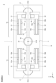
- FIG. 1 is a plan view illustrating a schematic configuration of a tuning fork type driving element and an optical deflection element according to the first embodiment.
- FIG. 2 is a cross-sectional view taken along the line C1-C2 of the first embodiment, viewed in the negative direction of the X-axis.
- 3A to 3C are diagrams each showing a schematic diagram of a procedure for forming an arm portion by etching according to the first embodiment.
- Fig. 4A is a cross-sectional view showing a state where the inclination of the side surface of the arm varies in accordance with the first embodiment.
- Fig. 1 is a plan view illustrating a schematic configuration of a tuning fork type driving element and an optical deflection element according to the first embodiment.
- FIG. 2 is a cross-sectional view taken along the line C1-C2 of the first embodiment, viewed in the negative direction of the X-axis.
- 3A to 3C are diagrams each showing a schematic diagram of a procedure
- 4B is a cross-sectional view showing a state where unnecessary vibrations are generated due to the variation in the inclination of the side surface of the arm in accordance with the first embodiment.
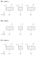
- 5(a) to (c) are cross-sectional views each showing a schematic configuration of an arm portion and a connecting portion of three tuning-fork type driving elements related to a simulation of the operation of the movable portion of the first embodiment.
- 6(a) and 6(b) are graphs showing the rate of displacement of the movable part in the X-axis and Y-axis directions, respectively, in a simulation of vibration of the movable part during resonant driving in the first embodiment.
- FIG. 7(a) and 7(b) are diagrams each showing a schematic diagram of a vibration state of a connecting portion according to the first embodiment.
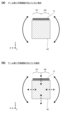
- 8(a) and 8(b) are diagrams for explaining processing of the arm portion according to the first embodiment.
- FIG. 9(a) and 9(b) are diagrams for explaining processing of the arm portion according to the first embodiment.
- FIG. 10 is a plan view illustrating a schematic configuration of a tuning-fork type driving element and a light deflection element according to a modification of the first embodiment.
- FIG. 11 is a plan view illustrating a schematic configuration of a tuning-fork type driving element and a light deflection element according to the second embodiment.
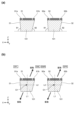
- FIG. 12A is a cross-sectional view showing a state where the inclination of the side surface of the arm varies according to the second embodiment.
- Fig. 12B is a cross-sectional view showing a state where unnecessary vibration occurs due to the variation in the inclination of the side surface of the arm according to the second embodiment.
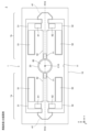
- FIG. 13 is a plan view illustrating a schematic configuration of a tuning-fork type driving element and a light deflection element according to the third embodiment.
- FIG. 14 is a block diagram showing a configuration of a drive device according to the third embodiment.
- FIG. 15 is a block diagram showing a configuration of a drive device according to a modification of the third embodiment.
- FIG. 16 is a plan view showing a schematic configuration of a tuning fork type driving element and a light deflection element according to another modified example.
- Fig. 17(a) is a partial plan view showing a pair of sensor units arranged symmetrically with respect to a central axis of an arm unit according to embodiment 2.
- Fig. 17(b) is a partial plan view showing a pair of drive units arranged symmetrically with respect to a central axis of an arm unit according to embodiment 3.
- each drawing is indicated with mutually orthogonal X, Y, and Z axes.
- the positive direction of the Z axis is the vertical upward direction.
- FIG. 1 is a plan view showing a schematic configuration of a tuning fork type driving element 1 and a light deflection element 2. As shown in FIG. 1
- the tuning fork type driving element 1 comprises a first driving unit 1a, a second driving unit 1b, a fixed part 10, and a movable part 20.
- the first driving unit 1a and the second driving unit 1b each comprise a pair of arm parts 31, 32 aligned in the X-axis direction, a support part 41, a connecting part 42, a pair of driving parts 51, 52, a pair of sensor parts 61, 62, and a sensor part 71.
- the tuning fork type driving element 1 is configured to be symmetrical in the X-axis direction and the Y-axis direction with respect to the center C10 in a plan view.
- a reflective surface 80 is formed on the upper surface of the movable part 20 to form the optical deflection element 2.
- the first drive unit 1a and the second drive unit 1b rotate the movable part 20 about the rotation axis R10 by a drive voltage supplied to the drive parts 51 and 52 from an external drive circuit (not shown).
- the reflecting surface 80 reflects the light incident from above the movable part 20 in a direction according to the swing angle of the movable part 20. As a result, the light (e.g., laser light) incident on the reflecting surface 80 is deflected and scanned as the movable part 20 rotates.
- the fixed part 10 is configured in a frame shape.
- the four arm parts 31, 32 and the two connecting parts 42 are located within an opening 11 that penetrates the center of the fixed part 10 in the Z-axis direction, and are disposed between the fixed part 10 and the movable part 20.
- the first drive unit 1a and the second drive unit 1b are disposed on the Y-axis negative side and the Y-axis positive side of the movable part 20, respectively.
- the pair of arm parts 31, 32 provided on the first drive unit 1a and the second drive unit 1b, respectively, are tuning fork-shaped in a plan view.
- the arm sections 31 and 32 are generally L-shaped in plan view.
- the pair of arm sections 31 and 32 aligned in the X-axis direction are positioned on either side of the rotation axis R10.
- the support part 41 connects the pair of arm parts 31, 32 and the connecting part 42 to the fixed part 10.
- the outer edge of the support part 41 in the Y-axis direction is connected to the fixed part 10.
- the connecting part 42 extends in the Y-axis direction from the movable part 20 along the rotation axis R10.
- the outer end of the connecting part 42 in the Y-axis direction is connected to the support part 41.
- the ends of the movable part 20 on the Y-axis positive side and the Y-axis negative side are connected to the inner ends of the pair of connecting parts 42 in the Y-axis direction.
- the movable part 20 has a substantially circular shape in a plan view.
- the movable part 20 is supported by the fixed part 10 via a pair of support parts 41 and a pair of connecting parts 42 so as to be rotatable about a rotation axis R10.
- the center of the movable part 20 coincides with the position of the center C10 of the tuning fork type driving element 1.
- the optical reflection film is formed on the upper surface of the movable part 20.
- the optical reflection film is made of a material with high reflectivity (for example, metals or metal compounds such as gold, silver, copper, or aluminum, or silicon dioxide or titanium dioxide).
- the optical reflection film may be made of a dielectric multilayer film.
- the upper surface of the optical reflection film forms a reflection surface 80 that reflects light.
- the reflection surface 80 may be formed by the upper surface of the movable part 20. In this case, the upper surface of the movable part 20 may be mirror-finished.
- Drive units 51 and 52 are formed on the upper surfaces of the portions of arm units 31 and 32 extending in the Y-axis direction.
- Drive unit 51 is connected to an electrode (not shown) on fixed unit 10 via wiring (not shown) on arm unit 31, support unit 41, and fixed unit 10
- drive unit 52 is connected to an electrode (not shown) on fixed unit 10 via wiring (not shown) on arm unit 32, support unit 41, and fixed unit 10. Cables (external wiring) leading to an external control circuit are connected to these electrodes on fixed unit 10 by wire bonding.
- a pair of arm units 31 located on the X-axis positive side of the rotation axis R10 and a pair of arm units 32 located on the X-axis negative side of the rotation axis R10 bend in opposite directions.
- the four arm units 31 and 32 are deformed, causing the movable unit 20 to rotate about the rotation axis R10.
- a drive voltage with a resonant frequency of a desired vibration mode is input to the drive units 51 and 52, causing the arm units 31 and 32 and the movable unit 20 to resonate.
- Sensor units 61 and 62 are formed on the upper surfaces of the portions of arm units 31 and 32 extending in the X-axis direction.
- Sensor unit 61 is connected to an electrode (not shown) on fixed unit 10 via arm unit 31, support unit 41, and wiring (not shown) on fixed unit 10
- sensor unit 62 is connected to an electrode (not shown) on fixed unit 10 via arm unit 32, support unit 41, and wiring (not shown) on fixed unit 10. Cables (external wiring) leading to an external control circuit are connected to these electrodes on fixed unit 10 by wire bonding.
- the sensor units 61, 62 formed on the arm units 31, 32, respectively, are deformed. This generates an electric charge due to the piezoelectric effect in the piezoelectric layer 112 (see FIG. 2) in the sensor units 61, 62, and a detection signal (current) is output to an external control circuit connected to the sensor units 61, 62. Based on the detection signals from the sensor units 61, 62, the vibration of the arm units 31, 32 is detected, and as a result, the rotation of the movable unit 20 is detected.
- the sensor unit 71 is formed on the upper surface of the connecting portion 42, and is disposed at a position near the end of the connecting portion 42 on the fixed portion 10 side.
- the sensor unit 71 is connected to an electrode (not shown) on the fixed portion 10 via the connecting portion 42, the support portion 41, and wiring (not shown) on the fixed portion 10.
- a cable (external wiring) that leads to an external control circuit is connected to this electrode on the fixed portion 10 by wire bonding.
- the sensor part 71 formed on the connecting part 42 deforms in response to the unwanted vibrations. This generates an electric charge due to the piezoelectric effect in the piezoelectric layer 112 (see FIG. 2) in the sensor part 71, and a detection signal (current) is output to an external control circuit connected to the sensor part 71.
- the unwanted vibrations occurring in the movable part 20 are detected based on the detection signal from the sensor part 71.
- the unwanted vibrations occurring in the movable part 20 will be described later with reference to FIGS. 7(a) and (b).
- Figure 2 is a cross-sectional view of the C1-C2 section in Figure 1, viewed in the positive direction of the Y axis.
- the arm portions 31, 32 and the connecting portion 42 are formed of a device layer 101 of an SOI substrate 100 (see FIG. 3A).
- the driving portions 51, 52 and the sensor portion 71 are formed on the upper surfaces of the arm portions 31, 32 and the connecting portion 42, respectively, and have a layer structure consisting of a lower electrode layer 111, a piezoelectric layer 112 and an upper electrode layer 113.
- the device layer 101 is made of, for example, silicon (Si).
- the lower electrode layer 111 is made of, for example, platinum (Pt).
- the piezoelectric layer 112 is a piezoelectric thin film, which is made of, for example, PZT (lead zirconate titanate: Pb(Zr,Ti) O3 ).
- the upper electrode layer 113 is made of, for example, gold (Au).
- the materials constituting the lower electrode layer 111, the piezoelectric layer 112, and the upper electrode layer 113 are not limited to the above materials and may be other materials.
- the sensor units 61 and 62 are also formed on the upper surfaces of the arm units 31 and 32 in the same configuration as the sensor unit 71.
- Figures 3(a) to (c) are diagrams that show the steps for forming the arm portions 31 and 32 by etching.
- Figures 3(a) to (c) show cross-sectional views of the C1-C2 section in Figure 1 as seen in the positive direction of the Y axis, and for convenience, only cross sections of the arm sections 31, 32 and the drive sections 51, 52 are shown. Also, although Figures 3(a) to (c) only show the vicinity of the arm sections 31, 32, the other parts of the tuning fork type drive element 1 are also similarly processed collectively.
- the SOI substrate 100 has a structure in which, from the top, a device layer 101, an oxide layer 102, and a handle layer 103 are stacked.
- the device layer 101 and the handle layer 103 are made of silicon (Si), and the oxide layer 102 is made of silicon dioxide (SiO 2 ).
- the driving units 51 and 52 are formed by stacking the lower electrode layer 111, the piezoelectric layer 112, and the upper electrode layer 113 shown in FIG. 2 on the upper surface of the SOI substrate 100.
- the sensor units 61, 62, and the sensor unit 71 are formed by stacking the lower electrode layer 111, the piezoelectric layer 112, and the upper electrode layer 113 shown in FIG. 2 on the upper surface of the SOI substrate 100.
- the device layer 101 is etched from the top side so that it has the same contour as the tuning fork-type driving element 1 in a plan view, and unnecessary portions of the device layer 101 are removed. In this way, the device layer 101 is left with the same contour as the arm portions 31 and 32, as shown in FIG. 3(b).
- the handle layer 103 is etched from the underside so that it has the same contour as the fixed portion 10 (see FIG. 1) in a plan view, and the handle layer 103 and oxide layer 102 are removed from areas other than the fixed portion 10.
- the handle layer 103 and oxide layer 102 are not removed from the area of the fixed portion 10, so the thickness of the fixed portion 10 increases. In this way, the arm portions 31 and 32 are formed as shown in FIG. 3(c).
- the side surface of the device layer 101 is shaped by plasma etching, which causes ions to be incident on the device layer 101.
- the device layer 101 is etched on a single circular SOI substrate 100 (wafer) using a dry etching device, and multiple tuning fork type driving elements 1 are collectively formed from a single SOI substrate 100.
- the inventors have found that the inclination of the side surface of the device layer 101 varies. This is thought to be because the collision angle of ions during plasma etching differs for each position on a single SOI substrate 100.
- Figure 4(a) is a cross-sectional view that shows a schematic diagram of the state in which the inclination of the side surfaces of the arm portions 31 and 32 varies.
- the angle between the side surface on the positive side of the X-axis and the X-Y plane is ⁇ 1, and the angle between the side surface on the negative side of the X-axis and the X-Y plane is ⁇ 2.
- the angle between the side surface on the positive side of the X-axis and the X-Y plane is ⁇ 1
- the angle between the side surface on the negative side of the X-axis and the X-Y plane is ⁇ 2.
- the positions of the arm portions 31 and 32 are close to each other, so the angles ⁇ 1 and ⁇ 2 formed by these arm portions 31 and 32 can be substantially the same. In other words, the asymmetry in the arm portion 31 and the asymmetry in the arm portion 32 are approximately equal.
- Figure 4(b) is a cross-sectional view that shows a schematic diagram of a state in which unwanted vibrations are generated due to variations in the inclination of the side surfaces of the arms 31 and 32.
- Figure 4(b) shows center line L1, which indicates the center of weight and shape in the X-axis direction, and center line L2, which indicates the center of weight and shape in the Z-axis direction, when arm portions 31 and 32 are properly molded.
- center line L1 which indicates the center of weight and shape in the X-axis direction
- center line L2 which indicates the center of weight and shape in the Z-axis direction
- arm portions 31 and 32 vibrate in opposite phases in the Z-axis direction, for example, in FIG. 4(b), when arm portion 31 is vibrating to the upper right, arm portion 32 is vibrating to the lower left, and when arm portion 31 is vibrating to the lower left, arm portion 32 is vibrating to the upper right.
- the inventors verified through simulation the operation of the movable part 20 when the side faces of the arm parts 31, 32 and the connecting part 42 are formed asymmetrically during processing of the device layer 101.
- Figures 5(a) to (c) are cross-sectional views that show schematic configurations of the arm portions 31, 32 and the connecting portion 42 of the three tuning fork-type driving elements (1) to (3), respectively, related to a simulation of the operation of the movable portion 20.
- Figures 5(a) to (c) are cross-sectional views of the arm parts 31, 32 and the connecting part 42 cut along a plane parallel to the X-Z plane, viewed in the positive direction of the Y axis.
- the side surfaces of the arms 31, 32 and the connecting part 42 on the positive and negative sides of the X-axis are all inclined at -5° with respect to the Y-Z axis directions.
- the side surfaces of the arms 31, 32 and the connecting part 42 on the positive and negative sides of the X-axis are not inclined with respect to the Y-Z axis directions.
- the side surfaces of the arms 31, 32 and the connecting part 42 on the positive and negative sides of the X-axis are all inclined at +5° with respect to the Y-Z axis directions.
- the inventors performed a simulation in which the four arms 31, 32 were vibrated by the driving units 51, 52 in these three tuning fork-type driving elements (1) to (3), causing the movable unit 20 to vibrate.
- Figures 6(a) and (b) are graphs showing the displacement rates of the movable part 20 in the X-axis and Y-axis directions, respectively, in a simulation of the vibration of the movable part 20 during resonant driving.
- FIG. 6(a) is a graph showing the displacement ratio in the Z-axis direction of a position on the movable part 20 that is a predetermined distance in the positive and negative X-axis directions from the center of the movable part 20.
- the displacement ratio in the Z-axis direction in FIG. 6(a) indicates a predetermined timing during one cycle of resonant driving, and shows the state when the end of the movable part 20 on the positive side of the X-axis is at its lowest and the end of the movable part 20 on the negative side of the X-axis is at its highest.
- Each displacement ratio in the Z-axis direction in FIG. 6(a) indicates the ratio to the maximum displacement of the tuning fork-type driving element (2).
- FIG. 6(b) is a graph showing the displacement ratio in the Z-axis direction of a position on the movable part 20 that is a predetermined distance from the center of the movable part 20 in the positive and negative Y-axis directions.
- the displacement ratio in the Z-axis direction in FIG. 6(b) indicates a predetermined timing during one period during resonant driving, and shows the state when the movable part 20 has shifted most upward in the driving element (3) whose side is inclined at +5°, and when the movable part 20 has shifted most downward in the driving element (1) whose side is inclined at -5°.
- Each displacement ratio in the Z-axis direction in FIG. 6(b) indicates the ratio to the maximum displacement amount of the tuning fork-type driving element (3).
- a sensor unit 71 is further disposed on the upper surface of the connecting portion 42.
- the detection signal of the sensor unit 71 it is possible to detect, based on the detection signal of the sensor unit 71, that unwanted vibrations other than proper rotation are occurring in the movable unit 20. Therefore, by referring to the detection signal of the sensor unit 71, additional processing can be performed to eliminate the asymmetry of the arm units 31, 32 so that this unwanted vibration is eliminated, and measures can be taken to properly vibrate the movable unit 20. Furthermore, by additional processing of the arm units 31, 32 so that unwanted vibrations are not generated in the movable unit 20, it is possible to improve both the unwanted vibrations and the decrease in drive efficiency.
- Figures 7(a) and (b) are diagrams that show the vibration state of the connecting part 42.
- Figures 7(a) and (b) are cross-sectional views of the connecting part 42 and the sensor part 71 cut along a plane parallel to the X-Z plane, viewed in the positive direction of the Y axis.
- the sensor unit 71 is arranged on the connecting portion 42 so as to be divided into two regions R1 and R2 in the X-axis direction, sandwiching the rotation axis R10 (see FIG. 1).
- the region on the positive side of the X-axis of the sensor unit 71 is R1
- the region on the negative side of the X-axis of the sensor unit 71 is R2.
- the sensor unit 71 includes a piezoelectric layer 112, and therefore a signal (current) corresponding to distortion (compression/expansion) is generated in regions R1 and R2 due to the piezoelectric effect.
- regions R1 and R2 are connected in the sensor unit 71, the sensor unit 71 outputs the difference between the signals induced from each of regions R1 and R2 as a detection signal for unwanted vibration.
- Figures 8(a) to 9(b) are diagrams for explaining the processing of the arm sections 31 and 32.
- Figures 8(a) to 9(b) are cross-sectional views of the arm sections 31 and 32 and the drive sections 51 and 52 cut along a plane parallel to the X-Z plane, viewed in the positive direction of the Y axis.
- FIG. 8(b) shows a state in which the portion 31a on the positive side of the X-axis has been cut so that both sides of the arm portion 31 are symmetrical in the X-axis direction, and the portion 32a on the positive side of the X-axis has been cut so that both sides of the arm portion 32 are symmetrical in the X-axis direction. This eliminates the imbalance in weight between the arm portions 31 and 32 in the X-axis direction, and suppresses unnecessary vibrations.
- the portions 31a, 32a near the positive side of the X-axis of the arm sections 31, 32 may be cut to eliminate the weight imbalance in the X-axis direction of the arm sections 31, 32, as shown in FIG. 9(a) and (b).
- the portions 31a, 32a may be cut off over the entire portion of the arm sections 31, 32 extending in the Y-axis direction in FIG. 8(b) to FIG. 9(b), or the portions 31a, 32a may be cut off from only a portion of the portion of the arm sections 31, 32 extending in the Y-axis direction.
- drive units 51, 52 are disposed on the respective arm units 31, 32 and rotate the movable unit 20.
- Sensor units 61, 62 are disposed to detect the rotation of the movable unit 20.
- Sensor unit 71 is disposed to detect unwanted vibrations occurring in the movable unit 20.
- the tuning fork type driving element 1 may have an asymmetry in the processed shape during the manufacturing process.
- the tuning fork type driving element 1 generates unwanted vibrations different from the originally intended vibrations, resulting in performance degradation such as a decrease in driving efficiency.
- the sensor unit 71 is arranged in the connecting portion 42 so that it is divided into two regions R1 and R2 on either side of the rotation axis R10, and outputs the difference in the signals induced from the respective regions R1 and R2 as a detection signal for unwanted vibration.
- the sensor unit 71 is disposed on the connecting portion 42 that is directly connected to the movable portion 20, so that the vibration state of the movable portion 20 can be directly detected. Furthermore, since the sensor unit 71 is configured as described above, if unwanted vibrations occur in the movable portion 20 when the movable portion 20 rotates, a detection signal corresponding to the unwanted vibrations is output from the sensor unit 71. This makes it easy to determine whether or not unwanted vibrations are present based on the detection signal from the sensor unit 71.
- the sensor unit 71 is disposed at a position near the end of the connecting part 42 on the fixed part 10 side.
- the sensor section 71 includes a piezoelectric layer 112, which is a piezoelectric thin film.
- the sensor unit 71 can be formed simultaneously with the formation of the drive units 51, 52 and the sensor units 61, 62, simplifying the manufacturing process.
- Two drive units a first drive unit 1a and a second drive unit 1b, each of which has a connecting portion 42, a pair of arm portions 31, 32, a support portion 41, drive portions 51, 52 (first drive portion), sensor portions 61, 62 (first sensor portion) and a sensor portion 71 (second sensor portion), are arranged in opposite directions across the movable portion 20, and the connecting portions 42 of the first drive unit 1a and the second drive unit 1b are connected to the movable portion 20.
- the movable part 20 can be supported and driven by the first drive unit 1a and the second drive unit 1b, so that the movable part 20 can be driven stably with a larger torque.
- unnecessary vibrations occurring in the first drive unit 1a and the second drive unit 1b can be smoothly detected based on the sensor parts 71 arranged in the first drive unit 1a and the second drive unit 1b, respectively.
- the optical deflection element 2 includes a tuning fork-type driving element 1 and a reflecting surface 80 disposed on the movable part 20.
- the optical deflection element 2 is equipped with the tuning fork type driving element 1 of the above configuration, it is possible to smoothly grasp the occurrence of unwanted vibrations on the reflective surface 80. As a result, measures can be taken to properly vibrate the reflective surface 80, and the light incident on the reflective surface 80 can be stably deflected in accordance with the vibration of the movable part 20.
- the sensor unit 71 is disposed at a position near the end of the connecting portion 42 on the fixed portion 10 side, but the position of the sensor unit 71 is not limited thereto.
- the sensor unit 71 may be disposed at a position near the end of the connecting portion 42 on the movable portion 20 side.
- FIG. 10 is a plan view that shows a schematic configuration of the tuning fork type driving element 1 and the optical deflection element 2 in this modified example.
- the sensor parts 71 of the first drive unit 1a and the second drive unit 1b are positioned near the end of the connecting part 42 on the movable part 20 side.
- the length of the wiring drawn from the sensor unit 71 to the fixed unit 10 is longer than in the first embodiment, but unwanted vibrations occurring in the connecting unit 42 close to the movable unit 20 can be detected. This allows unwanted vibrations occurring in the movable unit 20 to be detected more accurately.
- a sensor unit for detecting unwanted vibrations occurring in the movable part 20 is disposed on the arm parts 31 and 32 .
- FIG. 11 is a plan view that shows a schematic configuration of the tuning fork type driving element 1 and the optical deflection element 2 according to the second embodiment.
- the tuning fork type driving element 1 of the second embodiment omits the sensor unit 71, and has a pair of sensor units 91a, 91b arranged on the arm unit 31 and a pair of sensor units 92a, 92b arranged on the arm unit 32.
- the tuning fork type driving element 1 is configured to be symmetrical in the X-axis direction and the Y-axis direction with respect to the center C10 in a plan view.
- the pair of sensor units 91a, 91b are arranged on the arm unit 31 with the drive unit 51 sandwiched between them in the width direction of the arm unit 31 (X-axis direction), and are arranged on the positive side of the X-axis and the negative side of the X-axis of the drive unit 51, respectively.
- the lengths of the sensor units 91a, 91b are equal to each other, and in the Y-axis direction, the length of the sensor units 91a, 91b is equal to the length of the drive unit 51.
- the sensor units 91a, 91b are configured with a layered structure similar to that of the sensor unit 71 shown in FIG. 2.
- the pair of sensor units 92a, 92b are arranged on the arm unit 32, sandwiching the drive unit 52 in the width direction (X-axis direction) of the arm unit 32, and are arranged on the positive side of the X-axis and the negative side of the X-axis of the drive unit 52, respectively.
- the lengths of the sensor units 92a, 92b are equal to each other, and in the Y-axis direction, the length of the sensor units 92a, 92b is equal to the length of the drive unit 52.
- the sensor units 92a, 92b are configured with a layered structure similar to that of the sensor unit 71 shown in FIG. 2.
- Sensor units 91a and 91b are connected to electrodes (not shown) on fixed unit 10 via arm unit 31, support unit 41, and wiring (not shown) on fixed unit 10, and sensor units 92a and 92b are connected to electrodes (not shown) on fixed unit 10 via arm unit 32, support unit 41, and wiring (not shown) on fixed unit 10. Cables (external wiring) leading to an external control circuit are connected to these electrodes on fixed unit 10 by wire bonding.
- Sensor units 91a, 91b, 92a, and 92b each output a signal corresponding to the distortion of the position of the arm unit on which they are placed.
- Fig. 12(a) is a cross-sectional view showing a state in which the inclination of the side surfaces of the arm portions 31 and 32 varies in accordance with embodiment 2.
- Fig. 12(b) is a cross-sectional view showing a state in which unnecessary vibrations are generated due to the variation in the inclination of the side surfaces of the arm portions 31 and 32 in accordance with embodiment 2.
- the inclination of the side surfaces of the arm portions 31 and 32 can vary depending on the collision angle of the ions during plasma etching. If there is no variation in the side surfaces of the arm portions 31 and 32, the arm portions 31 and 32 vibrate only in the vertical direction by the drive portions 51 and 52. However, if there is variation in the inclination of the side surfaces as shown in FIG. 12(b), unnecessary vibrations in the horizontal direction are superimposed on the proper vertical vibrations, resulting in diagonal vibrations as shown by the thick arrow.
- the arm portions 31 and 32 vibrate in opposite phases in the Z-axis direction, so that, for example, in FIG. 12(b), when the arm portion 31 is vibrating to the upper right, the arm portion 32 is vibrating to the lower left, and when the arm portion 31 is vibrating to the lower left, the arm portion 32 is vibrating to the upper right.
- the signals output by the sensor units 91a and 91b are SPL and SML, respectively, and the signals output by the sensor units 92a and 92b are SMR and SPR, respectively.
- the signal components of the signals SPL and SML based on the vibration in the Z-axis direction are of the same polarity
- the signal components of the signals SMR and SPR based on the vibration in the Z-axis direction are of the same polarity
- the signal components of the signals SPL and SMR based on the vibration in the Z-axis direction are of opposite polarity.
- the signal components of the signals SPL and SPR based on the unwanted vibration in the X-axis direction are of the same polarity
- the signal components of the signals SML and SMR based on the unwanted vibration in the X-axis direction are of the same polarity
- the signal components of the signals SPL and SMR based on the unwanted vibration in the X-axis direction are of opposite polarity.
- the differential signal DS between the sum of the signals SPL and SPR and the sum of the signals SML and SMR is a signal that can detect unwanted vibrations occurring in the movable part 20 with high accuracy.
- the differential signal DS is expressed by the following formula F.
- the differential signal DS is a signal obtained based on the sensor units 91a, 91b, 92a, and 92b arranged on both of the pair of arms 31 and 32, rather than on just one of the pair of arms 31 and 32, and therefore contains components based on unwanted vibrations with high sensitivity. This allows unwanted vibrations to be detected with high accuracy.
- a pair of sensor units 91a, 91b (a pair of sensors) are arranged on the arm unit 31 in the width direction (X-axis direction) of the arm unit 31 with the drive unit 51 (first drive unit) sandwiched between them, and a pair of sensor units 92a, 92b (a pair of sensors) are arranged on the arm unit 31 in the width direction (X-axis direction) of the arm unit 32 with the drive unit 52 (first drive unit) sandwiched between them.
- the pair of sensor units 91a, 91b and the pair of sensor units 92a, 92b each output a signal corresponding to the distortion.
- unwanted vibrations occurring in the movable part 20 can be generated by driving the arm parts 31 and 32.
- the sensor parts 91a and 91b are arranged on the arm part 31, and the sensor parts 92a and 92b are arranged on the arm part 32, so that the unwanted vibrations generated at the source of the unwanted vibrations can be directly detected.
- a drive unit for suppressing unnecessary vibration of the arm portions 31 and 32 is disposed on each of the arm portions 31 and 32 .
- FIG. 13 is a plan view that shows a schematic configuration of the tuning fork type driving element 1 and the optical deflection element 2 according to the third embodiment.
- the tuning fork type driving element 1 of the third embodiment has a pair of driving units 93a, 93b arranged on the arm portion 31, and a pair of driving units 94a, 94b arranged on the arm portion 32.
- the tuning fork type driving element 1 is configured to be symmetrical in the X-axis direction and the Y-axis direction with respect to the center C10 in a plan view.
- the pair of drive units 93a, 93b are arranged on the arm unit 31, sandwiching the drive unit 51 in the width direction (X-axis direction) of the arm unit 31, and are arranged on the positive side of the X-axis and the negative side of the X-axis of the drive unit 51, respectively.
- the lengths of the drive units 93a, 93b are equal to each other in the X-axis and Y-axis directions.
- the drive units 93a, 93b are configured with a layered structure similar to that of the drive units 51, 52 shown in FIG. 2.
- the pair of drive units 94a, 94b are arranged on the arm unit 32, sandwiching the drive unit 52 in the width direction (X-axis direction) of the arm unit 32, and are arranged on the positive side of the X-axis and the negative side of the X-axis of the drive unit 52, respectively.
- the lengths of the drive units 94a, 94b are equal to each other in the X-axis and Y-axis directions.
- the drive units 94a, 94b are configured with the same layered structure as the drive units 51, 52 shown in FIG. 2.
- Drivers 93a and 93b are connected to electrodes (not shown) on fixed part 10 via arm part 31, support part 41, and wiring (not shown) on fixed part 10, and drivers 94a and 94b are connected to electrodes (not shown) on fixed part 10 via arm part 32, support part 41, and wiring (not shown) on fixed part 10. Cables (external wiring) leading to an external control circuit are connected to these electrodes on fixed part 10 by wire bonding.
- FIG. 14 is a block diagram showing the configuration of the drive unit 3.
- the drive device 3 comprises a tuning fork type drive element 1 or an optical deflection element 2, a control circuit 3a, and drive circuits 3b and 3c.
- FIG. 14 shows the connection between one of the first drive unit 1a and the second drive unit 1b, the control circuit 3a, and the drive circuits 3b and 3c, but the connection between the other drive unit, the control circuit 3a, and the drive circuits 3b and 3c is similar to the connection shown in FIG. 14.
- the processing of the control circuit 3a and the drive circuits 3b and 3c shown below is performed individually for the first drive unit 1a and the second drive unit 1b.
- the sensor units 61 and 62 are each connected to the control circuit 3a via an electrode of the fixed part 10.
- the drive units 51 and 52 are each connected to the drive circuit 3b via an electrode of the fixed part 10.
- the sensor units 91a, 91b, 92a, and 92b are each connected to the control circuit 3a via an electrode of the fixed part 10.
- the drive units 93a, 93b, 94a, and 94b are each connected to the drive circuit 3c via an electrode of the fixed part 10.
- the drive circuits 3b and 3c are each connected to the control circuit 3a.
- the control circuit 3a performs I/V conversion and digital conversion on the detection signals (currents) from the sensor units 61 and 62.
- the control circuit 3a adds the detection signal based on the sensor unit 61 and the detection signal based on the sensor unit 62 with the polarity of the inverted detection signal, and generates a drive signal to be applied to the drive units 51 and 52 so that the added detection signal approaches an ideal waveform when the arm units 31 and 32 are moving appropriately.
- the control circuit 3a generates a drive signal so that the amplitude, frequency, and phase of the added detection signal become the target amplitude, frequency, and phase.
- the drive circuit 3b performs analog conversion and amplification processing on the drive signal to be applied to the drive units 51 and 52, applies the processed drive signal (AC voltage) to the drive unit 51, and applies a drive signal with the polarity of the processed drive signal (AC voltage) inverted to the drive unit 52.
- This feedback control brings the arm units 31 and 32 closer to an ideal vibration state, and the movable unit 20 is resonantly driven at the target deflection angle and frequency.
- the control circuit 3a also performs I/V conversion and digital conversion on the detection signals (currents) from the sensor units 91a, 91b, 92a, and 92b.
- the control circuit 3a adds the detection signal based on the sensor unit 91a, the detection signal based on the sensor unit 91b with the polarity inverted, the detection signal based on the sensor unit 92a with the polarity inverted, and the detection signal based on the sensor unit 92b according to the above formula (F) to calculate the differential signal DS.
- the drive circuit 3c performs processes such as analog conversion and amplification on the differential signal DS to generate a drive voltage so that the differential signal DS becomes 0.
- the drive circuit 3c then inverts the polarity of the generated drive voltage and applies it to the drive unit 93a, applies the generated drive voltage to the drive unit 93b, applies the generated drive voltage to the drive unit 94a, inverts the polarity of the generated drive voltage and applies it to the drive unit 94b. This allows the drive units 93a, 93b, 94a, and 94b to suppress unnecessary vibrations of the arms 31 and 32.
- the differential signal DS is a signal obtained based on the sensor units 91a, 91b, 92a, and 92b arranged on both of the pair of arm units 31 and 32, rather than on just one of the pair of arm units 31 and 32, and therefore contains components based on unwanted vibrations with high sensitivity. This allows the unwanted vibrations to be grasped with high accuracy.
- the highly sensitive differential signal DS is used to generate signals to be applied to the drive units 93a, 93b, 94a, and 94b, so unwanted vibrations occurring in the movable unit 20 can be suppressed with high accuracy.
- the drive units 93a, 93b, 94a, and 94b suppress the unwanted vibrations, there is no need to perform processing to eliminate the asymmetry of the arm units 31 and 32.
- a pair of drive units 93a, 93b (second drive units) are arranged on the arm unit 31, sandwiching the drive unit 51 (first drive unit) in the width direction (X-axis direction) of the arm unit 31.
- a pair of drive units 94a, 94b (second drive units) are arranged on the arm unit 32, sandwiching the drive unit 52 (first drive unit) in the width direction (X-axis direction) of the arm unit 32.
- the driving units 93a, 93b, 94a, and 94b (second driving units) include a piezoelectric layer 112, which is a piezoelectric thin film.
- the driving units 93a, 93b, 94a, and 94b can be formed simultaneously with the formation of the driving units 51, 52, the sensor units 61, 62, and the sensor units 91a, 91b, 92a, and 92b, simplifying the manufacturing process.
- the drive device 3 includes a tuning fork type drive element 1 or an optical deflection element 2, and a control circuit 3a and drive circuits 3b and 3c (controllers) that drive drive units 93a, 93b, 94a, and 94b (second drive units) to suppress unnecessary vibrations of the arm units 31 and 32 based on signals output from sensor units 91a, 91b, 92a, and 92b (second sensor units).
- the unnecessary vibrations of the arm sections 31 and 32 which are the source of the unnecessary vibrations in the movable section 20, can be suppressed by controlling the drive sections 93a, 93b, 94a, and 94b based on the output from the sensor sections 91a, 91b, 92a, and 92b. Therefore, the unnecessary vibrations of the movable section 20 can be appropriately suppressed. Furthermore, since the unnecessary vibrations are suppressed by the drive sections 93a, 93b, 94a, and 94b, there is no need to perform processing to eliminate the asymmetry of the arm sections 31 and 32.
- the asymmetry of the processed shapes of the pair of arms 31 and 32 is assumed to be substantially the same, and a drive signal based on one difference signal DS is applied to the drivers 93a, 93b, 94a, and 94b as shown in Fig. 14.
- a drive signal based on one difference signal DS is applied to the drivers 93a, 93b, 94a, and 94b as shown in Fig. 14.
- the unwanted vibrations generated by the pair of arms 31 and 32 are different from each other.
- FIG. 15 is a block diagram showing the configuration of the drive unit 3 in this modified example.
- the drive device 3 of this modified example outputs four signals corresponding to the drive units 93a, 93b, 94a, and 94b, respectively, from the control circuit 3a to the drive circuit 3c.
- the control circuit 3a performs I/V conversion and digital conversion on the detection signals (currents) from the sensor units 91a, 91b, 92a, and 92b.
- the control circuit 3a outputs detection signals based on the sensor units 91a, 91b, 92a, and 92b to the drive circuit 3c.
- the drive circuit 3c performs processes such as analog conversion and amplification on the four detection signals output from the control circuit 3a.
- the drive circuit 3c applies the processed detection signal based on the sensor unit 91a to the drive unit 93b, applies the processed detection signal based on the sensor unit 91b to the drive unit 93a, applies the processed detection signal based on the sensor unit 92a to the drive unit 94b, and applies the processed detection signal based on the sensor unit 92b to the drive unit 94a.
- This allows the drive units 93a, 93b, 94a, and 94b to suppress unnecessary vibrations of the arm units 31 and 32.
- the first drive unit 1a and the second drive unit 1b are disposed on either side of the movable part 20 as shown in Figures 1, 10, 11 and 13, but one of the two drive units may be omitted.
- the second drive unit 1b may be omitted and the movable part 20 may be supported only by the connecting part 42 of the first drive unit 1a.
- the sensor units 91a and 91b are arranged on the opposite side of the movable unit 20 with respect to the drive units 93a and 93b, and the sensor units 92a and 92b are arranged on the opposite side of the movable unit 20 with respect to the drive units 94a and 94b.
- the sensor units 91a and 91b may be arranged on the movable unit 20 side with respect to the drive units 93a and 93b
- the sensor units 92a and 92b may be arranged on the movable unit 20 side with respect to the drive units 94a and 94b.
- the sensor units 61 and 62 are arranged on the arm units 31 and 32, respectively, as the first sensor unit for detecting the rotation of the movable unit 20, but a pair of sensor units may be arranged on the movable unit 20 as the first sensor unit.
- the pair of sensor units are arranged, for example, on the upper surface of the movable unit 20, respectively, on the X-axis positive side and the X-axis negative side of the rotation axis R10, symmetrically about the rotation axis R10.
- the sensor unit 71 is disposed near the movable part 20 or near the support part 41 in the connecting part 42, but it may be disposed both near the movable part 20 and near the support part 41. In addition, the sensor unit 71 may be disposed over the entire range of the connecting part 42 in the Y-axis direction.
- the length of the drive units 51 and 52 and the length of the sensor units 91a, 91b, 92a, and 92b in the Y-axis direction are equal to each other, but these two lengths may be different from each other.
- the sensor units 61, 62, 71, 91a, 91b, 92a, and 92b are configured to include a piezoelectric thin film, but they may be configured to include a strain resistance material.
- the strain resistance material is, for example, a strain resistance thin film or a strain resistance element in which silicon is doped with impurities. This allows the sensor units to function as strain gauges, and makes it possible to detect the deflection of the arrangement members (connecting portion 42 and arm portions 31 and 32) in the same way as sensor units that include a piezoelectric thin film. In this case, the external circuit to which the sensor units are connected is simplified, thereby reducing the cost of the external circuit.
- the sensor units 71, 91a, 91b, 92a, and 92b are configured to include a strain-resistance material, they can detect unintended displacement (for example, displacement in the X-axis direction) of the arranged member in a stationary state (DC state) in comparison with a sensor unit including a piezoelectric thin film.
- the tuning fork type driving element 1 is configured to be symmetrical in the X-axis direction and the Y-axis direction with respect to the center C10 in a plan view. Therefore, the sensor unit 71 (second sensor unit) has a shape that is symmetrical with respect to the rotation axis R10 in a plan view. With this configuration, when the movable part 20 rotates properly, the sensor unit 71 hardly outputs a detection signal, so that if unwanted vibrations occur in the movable part 20 in the X-axis direction or the Z-axis direction when the movable part 20 rotates, the unwanted vibrations can be detected efficiently.
- the sensor unit 71 only needs to have a shape that is substantially symmetrical about the rotation axis R10, and may have a shape that is slightly deviated from a symmetrical shape about the rotation axis R10, for example. However, if the sensor unit 71 has a shape that is significantly deviated from a symmetrical shape about the rotation axis R10, even when the movable part 20 rotates properly, a small detection signal will be output from the sensor unit 71, reducing the accuracy of the detection signal. For this reason, in order to detect unwanted vibrations with greater accuracy, it is preferable that the sensor unit 71 have a shape that is substantially symmetrical about the rotation axis R10, as described above.
- the pair of sensor units 91a, 91b are arranged on the arm unit 31 with the drive unit 51 sandwiched between them in the width direction (X-axis direction) of the arm unit 31, and the lengths of the sensor units 91a, 91b are equal to each other in the X-axis direction and the Y-axis direction.
- the pair of sensor units 92a, 92b are arranged on the arm unit 32 with the drive unit 52 sandwiched between them in the width direction (X-axis direction) of the arm unit 32, and the lengths of the sensor units 92a, 92b are equal to each other in the X-axis direction and the Y-axis direction.
- the pair of sensor units 91a, 91b are arranged symmetrically with respect to the central axis of the width direction (X-axis direction) of the arm unit 31 in a plan view, and the pair of sensor units 92a, 92b are arranged symmetrically with respect to the central axis of the width direction (X-axis direction) of the arm unit 32 in a plan view.
- the central axis of the width direction of the arm unit 31 is R11
- the central axis of the width direction of the arm unit 32 is R12.
- the pair of sensor units 91a, 91b are arranged symmetrically with respect to the central axis R11 in the width direction of the arm unit 31 on which the pair of sensor units 91a, 91b (pair of sensors) are arranged, and the pair of sensor units 92a, 92b (pair of sensors) are arranged symmetrically with respect to the central axis R12 in the width direction of the arm unit 32 on which the pair of sensor units 92a, 92b (pair of sensors) are arranged.
- the pair of sensor units 91a, 91b may be arranged substantially symmetrically with respect to the central axis R11, and may be arranged slightly offset from the symmetrical arrangement with respect to the central axis R11, for example.
- the pair of sensor units 92a, 92b may be arranged substantially symmetrically with respect to the central axis R12, and may be arranged slightly offset from the symmetrical arrangement with respect to the central axis R12, for example.
- the pair of sensor units are arranged significantly offset from the symmetrical arrangement with respect to the central axis, the accuracy of the differential signals (SPL-SML) and (SPR-SMR) decreases. Therefore, in order to increase the accuracy of these differential signals, it is preferable that the pair of sensor units are arranged substantially symmetrically with respect to the central axis, as described above.
- the pair of drivers 93a, 93b are arranged on the arm portion 31 with the driver 51 between them in the width direction (X-axis direction) of the arm portion 31, and the lengths of the drivers 93a, 93b are equal to each other in the X-axis and Y-axis directions.
- the pair of drivers 94a, 94b are arranged on the arm portion 32 with the driver 52 between them in the width direction (X-axis direction) of the arm portion 32, and the lengths of the drivers 94a, 94b are equal to each other in the X-axis and Y-axis directions.
- the pair of drive units 93a, 93b are arranged symmetrically with respect to the central axis of the width direction (X-axis direction) of the arm unit 31 in a plan view
- the pair of drive units 94a, 94b are arranged symmetrically with respect to the central axis of the width direction (X-axis direction) of the arm unit 32 in a plan view.
- the central axis of the width direction of the arm unit 31 is R11
- the central axis of the width direction of the arm unit 32 is R12.
- the pair of drive units 93a, 93b (pair of second drive units) are arranged symmetrically with respect to the central axis R11 in the width direction of the arm unit 31 on which the pair of drive units 93a, 93b (pair of second drive units) are arranged, and the pair of drive units 94a, 94b (pair of second drive units) are arranged symmetrically with respect to the central axis R12 in the width direction of the arm unit 32 on which the pair of drive units 94a, 94b (pair of second drive units) are arranged.
- the pair of drive units 93a, 93b may be arranged substantially symmetrically with respect to the central axis R11, and may be arranged slightly offset from the symmetrical arrangement with respect to the central axis R11, for example.
- the pair of drive units 94a, 94b may be arranged substantially symmetrically with respect to the central axis R12, and may be arranged slightly offset from the symmetrical arrangement with respect to the central axis R12, for example.
- the pair of drive units are arranged significantly offset from the symmetrical arrangement with respect to the central axis, it becomes difficult to apply approximately equal forces to both sides of the central axis of the arm unit. For this reason, in order to more efficiently suppress unnecessary vibrations generated in the arm units 31, 32, it is preferable that the pair of drive units are arranged substantially symmetrically with respect to the central axis, as described above.
- a movable part that is rotatable about a rotation axis; A connecting portion extending from the movable portion along the rotation axis; A pair of arms arranged on either side of the rotation axis; a support portion that connects the connecting portion and the pair of arms to a fixed portion; A first drive unit disposed on each of the arm units and configured to rotate the movable unit; A first sensor unit for detecting rotation of the movable part; A second sensor unit for detecting unnecessary vibrations generated in the movable part.
- a tuning fork type driving element characterized by:
- asymmetry may occur in the processed shape during the manufacturing process.
- unwanted vibrations different from the original intended vibrations occur in the tuning fork type driving element, resulting in performance degradation such as a decrease in driving efficiency.
- the above technology makes it possible to detect the occurrence of unwanted vibrations other than proper rotation in the moving part based on the detection signal of the second sensor unit. Therefore, even if unwanted vibrations occur in the moving part due to asymmetry in the processed shape of the tuning fork type driving element, the unwanted vibrations can be smoothly identified. This makes it possible to proceed with measures to ensure that the moving part vibrates properly, such as performing additional processing to eliminate the asymmetry.
- the second sensor unit includes a sensor arranged on the connecting portion so as to be divided into two regions with the rotation axis therebetween, The sensor outputs a difference between signals induced from each of the regions as a detection signal of the unwanted vibration.
- a tuning fork type driving element characterized by:
- the second sensor unit is disposed on a connecting part that is directly connected to the movable part, so that the vibration state of the movable part can be directly detected. Also, because the second sensor unit is configured as described above, if unwanted vibrations occur in the movable part when it rotates, a detection signal corresponding to the unwanted vibrations is output from the second sensor unit. This makes it easy to determine the presence or absence of unwanted vibrations based on the detection signal from the second sensor unit.
- the second sensor unit has a shape that is substantially symmetrical with respect to the rotation axis.
- a tuning fork type driving element characterized by:
- the second sensor part when the movable part rotates properly, the second sensor part hardly outputs a detection signal, so if unwanted vibrations occur in the movable part when it rotates, the unwanted vibrations can be detected efficiently.
- the second sensor unit is disposed at a position near an end of the connecting portion on the fixed portion side.
- a tuning fork type driving element characterized by:
- the length of the wiring can be shortened. This makes it possible to reduce noise contained in the signal from the second sensor unit.
- a tuning fork type driving element characterized by:
- This technology can detect unwanted vibrations that occur in the connecting parts close to the moving parts, so unwanted vibrations that occur in the moving parts can be detected accurately.
- the second sensor unit includes a pair of sensors disposed on the arm unit across the first drive unit in a width direction of the arm unit, Each of the pair of sensors outputs a signal corresponding to the distortion.
- a tuning fork type driving element characterized by:
- the driving of the first driving unit will cause unwanted vibrations in the arm portion other than the proper vibrations in the direction perpendicular to the surface of the arm portion.
- a difference occurs in the signals output from the pair of sensors. Therefore, this difference makes it possible to detect unwanted vibrations in the arm portion, and therefore unwanted vibrations in the moving part can be detected.
- unwanted vibrations in the moving part can be caused by driving the arm portion.
- the second sensor unit is disposed in the arm portion, and therefore unwanted vibrations caused at the source of the unwanted vibrations can be directly detected.
- a tuning fork type driving element characterized by:
- the pair of sensors output detection signals that are approximately equal to each other. Therefore, when detecting vibrations in the arm portion as the movable part rotates, unwanted vibrations occurring in the arm portion can be detected efficiently.
- Tuning fork type driving element In the tuning fork type driving element according to Technology 6 or 7, a pair of second drive units arranged on the arm unit with the first drive unit sandwiched therebetween in a width direction of the arm unit;
- a tuning fork type driving element characterized by:
- This technology makes it possible to suppress unwanted vibrations in the arm section by driving a pair of second drive units based on signals obtained from a pair of sensors.
- a tuning fork type driving element characterized by:
- the second driving section includes a piezoelectric thin film.
- a tuning fork type driving element characterized by:
- the second drive unit can be formed simultaneously with the formation of the first drive unit, the first sensor unit, and the second sensor unit, simplifying the manufacturing process.
- the second sensor unit includes a piezoelectric thin film.
- a tuning fork type driving element characterized by:
- the second sensor section can be formed simultaneously with the formation of the first drive section and the first sensor section, simplifying the manufacturing process.
- the second sensor portion includes a strain resistant material;
- a tuning fork type driving element characterized by:
- this technology makes it possible to detect unintended displacement of the component on which the second sensor unit is placed in a stationary state (DC state). This makes it possible to determine whether or not asymmetry has occurred in the processed shape of the arm unit, and whether or not there is a state in which unwanted vibrations may occur in the moving part.
- tuning fork type driving element In the tuning fork type driving element according to any one of the techniques 1 to 12, two drive units each including the coupling portion, the pair of arm portions, the support portion, the first drive portion, the first sensor portion, and the second sensor portion are disposed opposite to each other with the movable portion therebetween, The coupling portion of each of the drive units is connected to the movable portion.
- a tuning fork type driving element characterized by:
- the moving parts can be supported and driven by each drive unit, allowing the moving parts to be driven stably with greater torque.
- unnecessary vibrations occurring in each drive unit can be smoothly detected based on the second sensor units disposed in each drive unit.
- An optical deflection element comprising:
- the optical deflection element is equipped with a tuning fork-type driving element of the above configuration, so it is possible to smoothly detect the occurrence of unwanted vibrations on the reflective surface. This allows measures to be taken to properly vibrate the reflective surface, and the light incident on the reflective surface can be stably deflected in accordance with the vibration of the movable part.
- a tuning fork type driving element according to any one of techniques 8 to 10, a control unit that drives the second drive unit so as to suppress unnecessary vibration of the arm unit based on a signal output from the second sensor unit.
- a drive device characterized by:
- unwanted vibrations in the arm section which are a source of unwanted vibrations in the moving part
- the second drive section based on the output from the second sensor section. Therefore, unwanted vibrations in the moving part can be appropriately suppressed.
- unwanted vibrations are suppressed by the second drive section, there is no need to perform processing to eliminate asymmetry in the arm section.
- 1 tuning fork type driving element 1a first driving unit (driving unit) 1b Second drive unit (drive unit) 2 Optical deflection element 3 Driving device 3a Control circuit (control unit) 3b, 3c Drive circuit (control unit) 10 Fixed portion 20 Movable portion 31, 32 Arm portion 41 Support portion 42 Connection portion 51, 52 Drive portion (first drive portion) 61, 62 Sensor unit (first sensor unit) 71 Sensor unit (second sensor unit, sensor) 80 Reflecting surface 91a, 91b, 92a, 92b Sensor unit (second sensor unit, sensor) 93a, 93b, 94a, 94b Drive unit (second drive unit) 112 Piezoelectric layer (piezoelectric thin film) R1, R2 Area R10 Rotation axis R11, R12 Central axis
Landscapes
- Physics & Mathematics (AREA)
- General Physics & Mathematics (AREA)
- Optics & Photonics (AREA)
- Engineering & Computer Science (AREA)
- Computer Hardware Design (AREA)
- Microelectronics & Electronic Packaging (AREA)
- Gyroscopes (AREA)
Priority Applications (1)
| Application Number | Priority Date | Filing Date | Title |
|---|---|---|---|
| JP2025503636A JPWO2024180943A1 (https=) | 2023-02-27 | 2024-01-22 |
Applications Claiming Priority (2)
| Application Number | Priority Date | Filing Date | Title |
|---|---|---|---|
| JP2023-028947 | 2023-02-27 | ||
| JP2023028947 | 2023-02-27 |
Publications (1)
| Publication Number | Publication Date |
|---|---|
| WO2024180943A1 true WO2024180943A1 (ja) | 2024-09-06 |
Family
ID=92590320
Family Applications (1)
| Application Number | Title | Priority Date | Filing Date |
|---|---|---|---|
| PCT/JP2024/001719 Ceased WO2024180943A1 (ja) | 2023-02-27 | 2024-01-22 | 音叉型駆動素子、光偏向素子および駆動装置 |
Country Status (2)
| Country | Link |
|---|---|
| JP (1) | JPWO2024180943A1 (https=) |
| WO (1) | WO2024180943A1 (https=) |
Citations (6)
| Publication number | Priority date | Publication date | Assignee | Title |
|---|---|---|---|---|
| JP2001264663A (ja) * | 2000-03-21 | 2001-09-26 | Toshiba Corp | ミラー駆動機構 |
| JP2007025607A (ja) * | 2005-07-21 | 2007-02-01 | Brother Ind Ltd | 光走査装置、画像表示装置、光走査装置又は画像表示装置における反射ミラーの位置調節方法及び揺動状態検出方法 |
| JP2013186224A (ja) * | 2012-03-07 | 2013-09-19 | Panasonic Corp | 光学反射素子 |
| US20140118005A1 (en) * | 2012-10-26 | 2014-05-01 | Robert Bosch Gmbh | Mechanical component and manufacturing method for a mechanical component |
| JP2015055829A (ja) * | 2013-09-13 | 2015-03-23 | 株式会社リコー | 光偏向装置、画像形成装置、車両、光偏向装置の制御方法、及び光偏向装置の調整方法 |
| WO2023021777A1 (ja) * | 2021-08-19 | 2023-02-23 | パナソニックIpマネジメント株式会社 | 駆動素子 |
-
2024
- 2024-01-22 WO PCT/JP2024/001719 patent/WO2024180943A1/ja not_active Ceased
- 2024-01-22 JP JP2025503636A patent/JPWO2024180943A1/ja active Pending
Patent Citations (6)
| Publication number | Priority date | Publication date | Assignee | Title |
|---|---|---|---|---|
| JP2001264663A (ja) * | 2000-03-21 | 2001-09-26 | Toshiba Corp | ミラー駆動機構 |
| JP2007025607A (ja) * | 2005-07-21 | 2007-02-01 | Brother Ind Ltd | 光走査装置、画像表示装置、光走査装置又は画像表示装置における反射ミラーの位置調節方法及び揺動状態検出方法 |
| JP2013186224A (ja) * | 2012-03-07 | 2013-09-19 | Panasonic Corp | 光学反射素子 |
| US20140118005A1 (en) * | 2012-10-26 | 2014-05-01 | Robert Bosch Gmbh | Mechanical component and manufacturing method for a mechanical component |
| JP2015055829A (ja) * | 2013-09-13 | 2015-03-23 | 株式会社リコー | 光偏向装置、画像形成装置、車両、光偏向装置の制御方法、及び光偏向装置の調整方法 |
| WO2023021777A1 (ja) * | 2021-08-19 | 2023-02-23 | パナソニックIpマネジメント株式会社 | 駆動素子 |
Also Published As
| Publication number | Publication date |
|---|---|
| JPWO2024180943A1 (https=) | 2024-09-06 |
Similar Documents
| Publication | Publication Date | Title |
|---|---|---|
| JP7237146B2 (ja) | マイクロミラーデバイスおよびマイクロミラーデバイスの駆動方法 | |
| US8422109B2 (en) | Optical reflection element | |
| US7605966B2 (en) | Optical deflector | |
| JPWO2020085063A1 (ja) | マイクロミラーデバイスおよびマイクロミラーデバイスの駆動方法 | |
| JP2009265362A (ja) | ミアンダ形振動子およびこれを用いた光学反射素子 | |
| JP2000199714A (ja) | 角速度センサ | |
| WO2013114857A1 (ja) | 圧電アクチュエータデバイスとその製造方法 | |
| JP2009250859A (ja) | 加速度検知装置 | |
| JP2017009920A (ja) | 光走査装置 | |
| JP2000330067A (ja) | ねじり揺動体 | |
| JP2009192967A (ja) | 光学反射素子 | |
| JP2009265560A (ja) | 光学反射素子 | |
| JP2009258210A (ja) | 光学反射素子 | |
| JP2009258339A (ja) | 光学反射素子 | |
| JP2009223115A (ja) | 光学反射素子 | |
| JP2012149961A (ja) | 振動ジャイロ | |
| WO2024180943A1 (ja) | 音叉型駆動素子、光偏向素子および駆動装置 | |
| WO2018003692A1 (ja) | 物理量センサ | |
| JP2010060688A (ja) | 光学反射素子 | |
| WO2023162674A1 (ja) | 光学反射素子 | |
| JP2007326204A (ja) | アクチュエータ | |
| JP6733621B2 (ja) | 振動型角速度センサ | |
| JP2009244602A (ja) | 光学反射素子 | |
| JP2010249905A (ja) | 光学装置およびその製造方法 | |
| JP2009192781A (ja) | 光学反射素子 |
Legal Events
| Date | Code | Title | Description |
|---|---|---|---|
| 121 | Ep: the epo has been informed by wipo that ep was designated in this application |
Ref document number: 24763428 Country of ref document: EP Kind code of ref document: A1 |
|
| WWE | Wipo information: entry into national phase |
Ref document number: 2025503636 Country of ref document: JP |
|
| NENP | Non-entry into the national phase |
Ref country code: DE |
|
| 122 | Ep: pct application non-entry in european phase |
Ref document number: 24763428 Country of ref document: EP Kind code of ref document: A1 |