WO2024180763A1 - 音響信号出力システム、および音響信号出力方法 - Google Patents
音響信号出力システム、および音響信号出力方法 Download PDFInfo
- Publication number
- WO2024180763A1 WO2024180763A1 PCT/JP2023/007799 JP2023007799W WO2024180763A1 WO 2024180763 A1 WO2024180763 A1 WO 2024180763A1 JP 2023007799 W JP2023007799 W JP 2023007799W WO 2024180763 A1 WO2024180763 A1 WO 2024180763A1
- Authority
- WO
- WIPO (PCT)
- Prior art keywords
- acoustic signal
- point
- driver unit
- signal output
- area
- Prior art date
- Legal status (The legal status is an assumption and is not a legal conclusion. Google has not performed a legal analysis and makes no representation as to the accuracy of the status listed.)
- Ceased
Links
Images












Classifications
-
- H—ELECTRICITY
- H04—ELECTRIC COMMUNICATION TECHNIQUE
- H04R—LOUDSPEAKERS, MICROPHONES, GRAMOPHONE PICK-UPS OR LIKE ACOUSTIC ELECTROMECHANICAL TRANSDUCERS; ELECTRIC HEARING AIDS; PUBLIC ADDRESS SYSTEMS
- H04R1/00—Details of transducers, loudspeakers or microphones
- H04R1/20—Arrangements for obtaining desired frequency or directional characteristics
- H04R1/22—Arrangements for obtaining desired frequency or directional characteristics for obtaining desired frequency characteristic only
- H04R1/26—Spatial arrangements of separate transducers responsive to two or more frequency ranges
-
- H—ELECTRICITY
- H04—ELECTRIC COMMUNICATION TECHNIQUE
- H04R—LOUDSPEAKERS, MICROPHONES, GRAMOPHONE PICK-UPS OR LIKE ACOUSTIC ELECTROMECHANICAL TRANSDUCERS; ELECTRIC HEARING AIDS; PUBLIC ADDRESS SYSTEMS
- H04R1/00—Details of transducers, loudspeakers or microphones
- H04R1/20—Arrangements for obtaining desired frequency or directional characteristics
- H04R1/22—Arrangements for obtaining desired frequency or directional characteristics for obtaining desired frequency characteristic only
- H04R1/30—Combinations of transducers with horns, e.g. with mechanical matching means, i.e. front-loaded horns
-
- H—ELECTRICITY
- H04—ELECTRIC COMMUNICATION TECHNIQUE
- H04R—LOUDSPEAKERS, MICROPHONES, GRAMOPHONE PICK-UPS OR LIKE ACOUSTIC ELECTROMECHANICAL TRANSDUCERS; ELECTRIC HEARING AIDS; PUBLIC ADDRESS SYSTEMS
- H04R1/00—Details of transducers, loudspeakers or microphones
- H04R1/20—Arrangements for obtaining desired frequency or directional characteristics
- H04R1/32—Arrangements for obtaining desired frequency or directional characteristics for obtaining desired directional characteristic only
- H04R1/34—Arrangements for obtaining desired frequency or directional characteristics for obtaining desired directional characteristic only by using a single transducer with sound reflecting, diffracting, directing or guiding means
-
- H—ELECTRICITY
- H04—ELECTRIC COMMUNICATION TECHNIQUE
- H04R—LOUDSPEAKERS, MICROPHONES, GRAMOPHONE PICK-UPS OR LIKE ACOUSTIC ELECTROMECHANICAL TRANSDUCERS; ELECTRIC HEARING AIDS; PUBLIC ADDRESS SYSTEMS
- H04R3/00—Circuits for transducers
Definitions
- the present invention relates to an audio signal output system and to a technology for suppressing sound leakage to the surroundings.
- Technologies for providing audio guidance to target people include audio guide boards, tactile guide boards, audio signs, and other audio guide sign technologies.
- This disclosure has been made in light of these points, and aims to provide technology that allows audio to be played only to those individuals who are desired to take a specific action.
- the acoustic signal output system disclosed herein is an acoustic signal output system for use in a predetermined area including a first area for notifying a warning and a second area adjacent to the first area where the need for notifying a warning is lower than that of the first area, and includes a plurality of acoustic signal output devices disposed in or near the first area and emitting acoustic signals, and a control unit that controls the emission of the plurality of acoustic signal output devices using a sound source corresponding to the warning.
- each acoustic signal output device is assigned a different sub-area, has a concave reflector having an inner surface that is a paraboloid of revolution or a surface that is similar to a paraboloid of revolution, and a first driver unit disposed inside the reflector.
- the first acoustic signal is an acoustic signal emitted from the first driver unit to one side
- the second acoustic signal is an acoustic signal emitted from the first driver unit to the other side.
- the first acoustic signal When the first acoustic signal is emitted from one side of the first driver unit and the second acoustic signal is emitted from the other side of the first driver unit, the first acoustic signal reaches a predetermined point, which is a point farther from the acoustic signal output device than the first point based on a first point in the first sub-area of the assigned sub-area, and the attenuation rate of the first acoustic signal at a second point in the second sub-area of the assigned sub-area is configured to be equal to or less than a predetermined value smaller than the attenuation rate of the acoustic signal due to air propagation at the second point based on the first point.
- the attenuation amount of the first acoustic signal at the second point based on the first point is configured to be equal to or greater than a predetermined value larger than the attenuation amount of the acoustic signal due to air propagation at the second point based on the first point.
- This configuration reduces sound leakage to the surrounding area, allowing specific audio signals to be played only to those individuals who are to take a specific action.
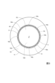
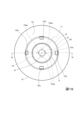
- FIG. 1 is a see-through front view illustrating the configuration of an acoustic signal output device according to a first embodiment.
- FIG. 2 is a transparent plan view illustrating the configuration of the acoustic signal output device according to the first embodiment.
- FIG. 3 is a cross-sectional view taken along line 1-1 of FIG.
- FIG. 4 is a cross-sectional view taken along line 2-2 of FIG.
- FIG. 5 is a conceptual diagram illustrating the arrangement of sound holes.
- FIG. 6 is a conceptual diagram for explaining the relationship between the paraboloid of revolution and the focal point.
- Fig. 7A is a conceptual diagram for explaining the direction of travel of an acoustic signal when a driver unit is placed at the focal point of a paraboloid of revolution.
- Fig. 7A is a conceptual diagram for explaining the direction of travel of an acoustic signal when a driver unit is placed at the focal point of a paraboloid of revolution.
- Fig. 7A is a conceptual diagram for
- FIG. 7B is a conceptual diagram for explaining the direction of travel of an acoustic signal when a driver unit is not placed at the focal point of a paraboloid of revolution.
- Fig. 8A is a conceptual diagram illustrating a configuration in which a horn is attached to a driver unit
- Fig. 8B is a conceptual diagram illustrating an arrangement configuration of the acoustic signal output device of the first embodiment.
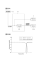
- Fig. 9A is a block diagram illustrating a functional configuration for supplying a signal to a driver unit
- Fig. 9B is a diagram illustrating a sound pressure level at an observation point.
- 10A and 10B are graphs for illustrating the directional characteristics of an acoustic signal output device.
- FIG. 11A and 11B are graphs for illustrating the directional characteristics of an acoustic signal output device.
- FIG. 12 is a graph illustrating the directional characteristics of the acoustic signal output device.
- 13A and 13B are graphs illustrating the frequency characteristics of the acoustic signal output device.
- 14A and 14B are graphs illustrating the frequency characteristics of the acoustic signal output device.
- FIG. 15 is a graph illustrating the frequency characteristics of the acoustic signal output device.
- FIG. 16 is a front view illustrating a modified example of the arrangement of the sound holes.
- FIG. 17 is a front view illustrating a modified example of the arrangement of the sound holes.
- FIG. 16 is a front view illustrating a modified example of the arrangement of the sound holes.
- FIG. 18 is a see-through front view illustrating the configuration of an acoustic signal output device according to a modified example of the first embodiment.
- FIG. 19 is a transparent plan view illustrating the configuration of an acoustic signal output device according to a modified example of the first embodiment.
- Fig. 20A is a transparent plan view illustrating the configuration of a housing of a modified example of the first embodiment
- Fig. 20B is a transparent front view illustrating the configuration of the housing of a modified example of the first embodiment
- Fig. 20C is a bottom view illustrating the configuration of the housing of the modified example of the first embodiment.
- FIG. 21 is a cross-sectional view taken along line 19-19 of FIG.
- FIG. 22A and 22B are cross-sectional views for illustrating the configuration of an acoustic signal output device according to a modified example of the first embodiment.
- FIG. 23 is a see-through front view illustrating the configuration of an acoustic signal output device according to the second embodiment.
- FIG. 23 is a transparent plan view illustrating the configuration of an acoustic signal output device according to the second embodiment.
- FIG. 25 is a see-through front view illustrating the configuration of an acoustic signal output device according to a modified example of the second embodiment.
- FIG. 26 is a see-through front view illustrating the configuration of an acoustic signal output device according to a modified example of the second embodiment.
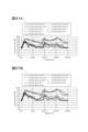
- FIG. 27A is a graph illustrating the frequency characteristics of an acoustic signal observed on the cutout side
- Fig. 27B is a graph illustrating the frequency characteristics of an acoustic signal observed on the side where no cutout is provided
- Fig. 28A is a graph illustrating the frequency characteristics of an acoustic signal observed on a side with a cutout and a side without a cutout
- Fig. 28B is a graph illustrating the difference in frequency characteristics of an acoustic signal due to the difference in the cutout.
- FIG. 29 is a see-through front view illustrating the configuration of an acoustic signal output device according to the third embodiment.
- FIG. 30A is a block diagram illustrating a functional configuration for supplying a signal to a driver unit.
- Fig. 30B is a diagram illustrating a sound pressure level at an observation point.
- FIG. 31 is a block diagram illustrating the functional configuration of the acoustic signal output system according to the fourth embodiment.
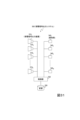
- Fig. 32A is a diagram showing an acoustic signal output system according to the fourth embodiment applied to a railway station as viewed from above
- Fig. 32B is a diagram showing the railway station of Fig. 32A as viewed from the longitudinal direction of the platform.
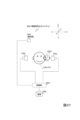
- Fig. 33A is a diagram showing an acoustic signal output system according to the fourth embodiment applied to a roadside construction site as viewed from above, and Fig.
- FIG. 33B is a diagram showing Fig. 33A as viewed from the roadside direction.
- FIG. 34 is a simplified diagram of the predetermined region PL for explaining the sub-region ST.
- FIG. 35 is an image diagram showing the acoustic signal reaching the second region T2.
- FIG. 36 is a diagram showing an example of a processing flow of the acoustic signal output system according to the fourth embodiment.
- FIG. 37 is a block diagram illustrating the functional configuration of the acoustic signal output system according to the fifth embodiment.
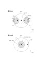
- Fig. 38A is a diagram showing the first region T'1 and the second region T'2 when Fig. 37 is viewed from the XZ plane.
- Fig. 38A is a diagram showing the first region T'1 and the second region T'2 when Fig.
- FIG. 39 is a diagram showing an example of a processing flow of the acoustic signal output system according to the fifth embodiment.
- FIG. 40 is a diagram showing another example of a processing flow of the acoustic signal output system according to the fifth embodiment.
- an audio signal output system according to an embodiment of the present invention has an audio signal output device. Various embodiments of this audio signal output device are possible. Therefore, embodiments of the audio signal output device used in this system will be described as first to third embodiments. Then, an audio signal output system according to an embodiment of the present invention will be described as fourth to fifth embodiments.
- the acoustic signal output device 10 of this embodiment is a device for listening to sound (e.g., open-ear type earphones, headphones, installed speakers, embedded speakers, etc.) that is worn without sealing the user's ear canal. As illustrated in Figs.
- the acoustic signal output device 10 of this embodiment has a concave (e.g., parabolic) reflector 13 having a paraboloid of revolution or a surface similar to a paraboloid of revolution on the inside, driver units 11 and 15 (speaker driver units, drivers) that convert an output signal (electrical signal representing an acoustic signal) output from a playback device into an acoustic signal and output it, a housing 16 that houses the driver unit 15 inside, and a support part 14 for placing the driver unit 11 inside the reflector 13.
- a concave e.g., parabolic
- driver units 11 and 15 that convert an output signal (electrical signal representing an acoustic signal) output from a playback device into an acoustic signal and output it
- housing 16 that houses the driver unit 15 inside
- a support part 14 for placing the driver unit 11 inside the reflector 13.
- the frequency band of the reproduced acoustic signal (reproduced acoustic signal) is divided into a high frequency band and a low frequency band, and the driver unit 11 emits the high frequency band acoustic signal of the reproduced acoustic signal. That is, the driver unit 11 mainly handles high frequency acoustic signals of the reproduced acoustic signal.
- the output signal output from the reproduction device is separated into a high frequency band signal on the high frequency side and a low frequency band signal on the lower frequency side, and the high frequency band signal separated in this manner is input to the driver unit 11.
- the driver unit 11 is a device (device with a speaker function) that emits (emits sound) an acoustic signal AC1 (first acoustic signal) based on the input high frequency band signal to one side (D1 direction side), and emits an acoustic signal AC2 (second acoustic signal) that is an inverse phase signal (phase inversion signal) of the acoustic signal AC1 or an approximation signal of the inverse phase signal to the other side (D2 direction side).
- a device device with a speaker function
- an acoustic signal emitted from the driver unit 11 to one side is called an acoustic signal AC1 (first acoustic signal)
- an acoustic signal emitted from the driver unit 11 to the other side is called an acoustic signal AC2 (second acoustic signal).
- the driver unit 11 is disposed near an axis A1 (axis) extending along the D1 direction or the axis A1 (axis), and the acoustic signals AC1 and AC2 are emitted along the axis A1 (axis).
- the driver unit 11 includes a diaphragm 113 that emits an acoustic signal AC1 in the D1 direction from one surface 113a by vibration, and emits an acoustic signal AC2 in the D2 direction from the other surface 113b by this vibration (FIG. 1).
- the diaphragm 113 is disposed near the axis A1 (axis) or the axis A1 (axis).
- the driver unit 11 emits the acoustic signal AC1 from the surface 111 on one side in the D1 direction by vibrating the diaphragm 113 based on the input high-frequency band signal, and emits the acoustic signal AC2, which is an inverse phase signal of the acoustic signal AC1 or an approximation of the inverse phase signal, from the surface 112 on the other side in the D2 direction. That is, the acoustic signal AC2 is emitted secondarily with the emission of the acoustic signal AC1.
- the D2 direction (the other side) is, for example, the opposite direction to the D1 direction (one side), but the D2 direction does not need to be strictly the opposite direction to the D1 direction, as long as the D2 direction is different from the D1 direction.
- the relationship between the one side (D1 direction) and the other side (D2 direction) depends on the type and shape of the driver unit 11.
- the acoustic signal AC2 may be strictly an inverse phase signal of the acoustic signal AC1, or the acoustic signal AC2 may be an approximation of the inverse phase signal of the acoustic signal AC1.
- the approximation signal of the opposite phase signal of the acoustic signal AC1 may be (1) a signal obtained by shifting the phase of the opposite phase signal of the acoustic signal AC1, (2) a signal obtained by changing (amplifying or attenuating) the amplitude of the opposite phase signal of the acoustic signal AC1, or (3) a signal obtained by shifting the phase of the opposite phase signal of the acoustic signal AC1 and further changing the amplitude.
- the phase difference between the opposite phase signal of the acoustic signal AC1 and its approximation signal is desirably ⁇ 1% or less of one period of the opposite phase signal of the acoustic signal AC1.
- Examples of ⁇ 1% are 1%, 3%, 5%, 10%, 20%, etc.
- the difference between the amplitude of the opposite phase signal of the acoustic signal AC1 and the amplitude of its approximation signal is desirably ⁇ 2% or less of the amplitude of the opposite phase signal of the acoustic signal AC1.
- Examples of ⁇ 2% are 1%, 3%, 5%, 10%, 20%, etc.
- examples of the type of the driver unit 11 include a dynamic type, a balanced armature chair type, a hybrid type of a dynamic type and a balanced armature type, and a capacitor type.
- the outer shape of the driver unit 11 is a substantially cylindrical shape with both end faces, and the diaphragm 113 is a substantially disc shape, but this does not limit the present invention.
- the outer shape of the driver unit 11 may be a rectangular parallelepiped shape, and the diaphragm 113 may be a dome shape.
- examples of the acoustic signal include music, voice, sound effects, environmental sounds, and other sounds.
- the driver unit 15 of this embodiment is disposed on the D2 direction side of the driver unit 11.
- the driver unit 15 is larger in size than the driver unit 11, and emits the low-frequency band acoustic signal among the above-mentioned reproduced acoustic signals. That is, the driver unit 15 mainly handles low-frequency acoustic signals among the reproduced acoustic signals. This makes it possible to obtain low-frequency sound pressure compared to the case where only the driver unit 11 is used.
- the driver unit 15 is a device (device having a speaker function) that emits (emits sound) an acoustic signal AC3 (third acoustic signal) based on the input low-frequency band signal to one side (D1 direction side), and emits an acoustic signal AC4 (fourth acoustic signal) which is an inverse phase signal (phase inversion signal) of the acoustic signal AC3 or an approximation signal of the inverse phase signal to the other side (D2 direction side).
- a device device having a speaker function
- the acoustic signal emitted from the driver unit 15 to one side is called acoustic signal AC3 (third acoustic signal), and the acoustic signal emitted from the driver unit 15 to the other side (D2 direction side) is called acoustic signal AC4 (fourth acoustic signal).
- the driver unit 15 is arranged on the axis A1 (axis) or in the vicinity of the axis A1 (axis), and the acoustic signals AC3 and AC4 are emitted along the axis A1 (axis).
- the driver unit 15 includes a diaphragm 153 (second diaphragm) that emits an acoustic signal AC3 (third acoustic signal) from one surface 153a to the D1 direction side (one side) by vibration, and emits an acoustic signal AC4 (fourth acoustic signal) from the other surface 153b to the D2 direction side (other side) by this vibration (FIG. 12).
- the diaphragm 153 is arranged on the axis A1 (axis) or in the vicinity of the axis A1 (axis).
- the driver unit 15 emits the acoustic signal AC3 from one side surface 151 in the direction D1 by vibrating the diaphragm 153 based on the input low-frequency band signal, and emits the acoustic signal AC4, which is an in-phase signal or an approximation signal of the in-phase signal of the acoustic signal AC3, from the other side surface 152 in the direction D2. That is, the acoustic signal AC4 is emitted secondarily in association with the emission of the acoustic signal AC3.
- the acoustic signal AC3 is an in-phase signal or an approximation signal of the in-phase signal of the acoustic signal AC1
- the acoustic signal AC4 is an in-phase signal or an approximation signal of the in-phase signal of the acoustic signal AC2.
- the acoustic signal AC4 may be strictly an in-phase signal of the acoustic signal AC3, or the acoustic signal AC4 may be an approximation signal of the in-phase signal of the acoustic signal AC3.
- the approximation signal of the opposite phase signal of the acoustic signal AC3 may be (1) a signal obtained by shifting the phase of the opposite phase signal of the acoustic signal AC3, (2) a signal obtained by changing (amplifying or attenuating) the amplitude of the opposite phase signal of the acoustic signal AC3, or (3) a signal obtained by shifting the phase of the opposite phase signal of the acoustic signal AC3 and further changing the amplitude.
- the phase difference between the opposite phase signal of the acoustic signal AC3 and its approximation signal is desirably ⁇ 3% or less of one period of the opposite phase signal of the acoustic signal AC3.
- Examples of ⁇ 3% are 1%, 3%, 5%, 10%, 20%, etc.
- the difference between the amplitude of the opposite phase signal of the acoustic signal AC3 and the amplitude of its approximation signal is desirably ⁇ 4% or less of the amplitude of the opposite phase signal of the acoustic signal AC3.
- Examples of ⁇ 4% are 1%, 3%, 5%, 10%, 20%, etc.
- examples of the type of the driver unit 15 include a dynamic type, a balanced armature chair type, a hybrid type of a dynamic type and a balanced armature type, and a condenser type.
- the outer shape of the driver unit 15 is a substantially cylindrical shape with both end faces, and the diaphragm 153 is a substantially disc shape, but this does not limit the present invention.
- the outer shape of the driver unit 15 may be a rectangular parallelepiped shape, and the diaphragm 153 may be a dome shape.
- the driver unit 15 is larger in size than the driver unit 11.
- the diameter of the driver unit 11 (diameter in the direction perpendicular to the D1 direction and/or the D2 direction) is S11 and the diameter of the driver unit 15 (diameter in the direction perpendicular to the D1 direction and/or the D2 direction) is S21, then S21>S11 is satisfied.
- S21 is more than twice as large as S11, S11 is 12 mm, and S21 is 35 mm.
- the diameter of the diaphragm 113 (diameter in the direction perpendicular to the D1 direction and/or the D2 direction) is S12 and the diameter of the diaphragm 153 (diameter in the direction perpendicular to the D1 direction and/or the D2 direction) is S22, then S22>S12 is satisfied.
- S22 is more than twice as large as S12, S12 is 10 mm, and S22 is 30 mm. That is, the diameter of diaphragm 153 (second diaphragm) is larger than the diameter of diaphragm 113 (first diaphragm).
- the reflector 13 is a concave structure having a paraboloid of revolution or a surface approximating a paraboloid of revolution on the inside. That is, at least a part of the inner wall surface 131 of the reflector 13 is a paraboloid of revolution or a surface approximating a paraboloid of revolution.
- This paraboloid of revolution has a shape obtained by rotating a parabola around the axis A1 (a specific axis), for example.
- the entire inner wall surface 131 may be a paraboloid of revolution or a surface approximating a paraboloid of revolution, or only a part of the inner wall surface 131 (for example, only the inner wall surface 131 on the bottom 131a side of the reflector 13 or only the inner wall surface 131 on the tip 131c side) may be a paraboloid of revolution or a surface approximating a paraboloid of revolution.
- the driver unit 11 is disposed inside the reflector 13.
- the driver unit 11 is fixed to an inner wall surface 131 of the reflector 13 via a support 14.
- one surface 111 of the driver unit 11 disposed inside the reflector 13 faces the open end 130 side (D1 direction side) of the reflector 13, and the other surface 112 faces the bottom 131a side (D2 direction side) of the reflector 13.
- the driver unit 11 (first driver unit) emits an acoustic signal AC1 (first acoustic signal) to the D1 direction side (one side) of the driver unit 11, and emits an acoustic signal AC2 (second acoustic signal) to the D2 direction side (other side) of the driver unit 11.
- the acoustic signal AC1 (reproduced acoustic signal) emitted from the driver unit 11 is emitted outward from the open end 130 on the D1 direction side of the reflector 13.
- a part of the acoustic signal AC1 is emitted directly from the driver unit 11 to the D1 direction side of the reflector 13.
- At least another part of the acoustic signal AC1 is reflected by the inner wall surface 131 of the reflector 13 and then emitted from the open end 130 to the D1 direction side.
- At least a part of the acoustic signal AC2 is reflected by the inner wall surface 131 of the reflector 13 and then emitted from the open end 130 to the D1 direction side.
- a user located on the D1 direction side can hear the acoustic signal AC1 emitted from the open end 130 of the reflector 13.
- the reflector 13 suppresses sound leakage of the acoustic signal AC1 to the back surface 132 side of the reflector 13.
- the acoustic signal AC2 is an inverse phase signal of the acoustic signal AC1 or an approximation signal of the inverse phase signal. Therefore, at a specific position on the D1 direction side other than where the user is present (for example, a position behind the user), a part of the acoustic signal AC1 cancels out a part of the acoustic signal AC2, suppressing sound leakage of the acoustic signal AC1.
- the driver unit 11 is disposed on the axis A1, and for example, it is desirable that the diaphragm 113 is disposed on the axis A1. More preferably, it is desirable that the center of the diaphragm 113 or its vicinity is disposed on the axis A1. In other words, it is desirable that the diaphragm 113 is disposed at the center or near the center of the above-mentioned paraboloid of revolution. This is because the sound pressure of the acoustic signal AC1 emitted from the open end 130 becomes axially symmetric or approximately axially symmetric with respect to the axis A1.
- the driver unit 11 is disposed at the focal point or near the focal point of this paraboloid of revolution.
- the directivity of the acoustic signal AC1 emitted from the open end 130 becomes high.
- the point on the parabola constituting the paraboloid of revolution is (x, y)
- the focal point of the paraboloid of revolution is P(0, p)
- the center of the traveling direction of the acoustic signal AC1 emitted from the open end 130 is parallel to the Y axis (axis A1).
- the driver unit 11 when the driver unit 11 is arranged at the focal point P(0, p) or in the vicinity of the focal point P(0, p) of the paraboloid of revolution, the directivity of the acoustic signal AC1 emitted from the open end 130 becomes high.
- the driver unit 11 when the driver unit 11 is arranged at a position (0, q) that is shifted from the vicinity of the focal point P(0, p) or the focal point P(0, p) of the paraboloid of revolution (p ⁇ q), the center of the traveling direction of the acoustic signal AC1 emitted from the open end 130 spreads outward with respect to the Y axis.
- the directivity of the acoustic signal AC1 emitted from the reflector 13 is lower than when the driver unit 11 is disposed at the focus P(0,p) of the paraboloid of revolution or in the vicinity of the focus P(0,p).
- a part of the acoustic signal AC2 is also emitted from the open end 130 in the D1 direction after being reflected by the inner wall surface 131 of the reflector 13.
- the acoustic signal AC2 is an inverse phase signal of the acoustic signal AC1 or an approximation of the inverse phase signal.
- the high-frequency components have short wavelengths and are less likely to cancel each other out. Therefore, on the D1 direction side, the sound pressure of the high-frequency components of the acoustic signal AC1 can be sufficiently secured.
- the mid- and low-frequency components of the acoustic signals AC1 and AC2 emitted from the open end 130 have low directivity and are more likely to leak to the back surface 132.
- the acoustic signal AC2 is an inverse phase signal of the acoustic signal AC1 or an approximation signal of the inverse phase signal, and these low-frequency components have long wavelengths and tend to cancel each other out.
- the acoustic signal AC2 it is ideal that the difference between the propagation distance from the surface 111 on one side of the driver unit 11 to the position where sound leakage is to be suppressed and the propagation distance from the surface 112 on the other side of the driver unit 11 to the position where sound leakage is to be suppressed is an integer multiple (including the same) of the wavelengths of the acoustic signals AC1 and AC2.
- the reflector 13 of this embodiment is provided with one or more sound holes 131b (reflector sound holes).
- the sound hole 131b also serves to weaken the directivity of the high-frequency components of the acoustic signals AC1 and AC2. If the sound pressure of the high-frequency components is too high, it may be harsh to the ear, but by providing the sound hole 131b, the sound pressure of the high-frequency components of the acoustic signals AC1 and AC2 emitted in the direction D1 can be weakened.
- FIG. 2 and other figures show an example in which four rectangular sound holes 131b are arranged in the reflector 13 symmetrically or approximately symmetrically with respect to the axis A1.
- sound holes 131b such as circular or triangular may be provided, multiple sound holes 131b with different shapes and sizes may be provided, or the sound holes 131b may be arranged in a biased manner in one position.
- the sound holes 131b may be arranged in a biased manner in a direction in which sound leakage of the acoustic signal AC1 becomes a problem. As illustrated in Figs.
- the sound hole 131b is preferably disposed near the D2 direction side (the other side) of the driver unit 11 (first driver unit) or the D2 direction side (the other side) of the driver unit 11 (first driver unit). This makes it difficult for the acoustic signal AC1 emitted from the D1 direction side of the driver unit 11 to be emitted from the sound hole 131b, and makes it easy for the acoustic signal AC2 emitted from the D2 direction side of the driver unit 11 to be emitted from the sound hole 131b. As a result, it becomes easy to adjust the difference in the propagation distance between the above-mentioned acoustic signal AC1 and the acoustic signal AC2 depending on the size, number, arrangement, etc.
- the sound hole 131b is, for example, a sound hole that penetrates the reflector 13, but this does not limit the present invention. If the acoustic signal inside the reflector 13 can be led out to the outside, the sound hole 131b does not have to be a through hole.
- the edge of the open end of sound hole 131b is quadrangular (the open end is square), but this does not limit the present invention.
- the edge of the open end of sound hole 131b may be circular, elliptical, triangular, or other shapes.
- the open end of sound hole 131b may also be mesh-like.
- the acoustic signal AC1 (first acoustic signal) is emitted from the D1 direction side (one side) of the driver unit 11 (first driver unit), and the acoustic signal AC2 (second acoustic signal) is emitted from the D2 direction side (the other side) of the driver unit 11 (first driver unit), so that the attenuation rate ⁇ 11 of the acoustic signal AC1 (first acoustic signal) at the position P2 (second point) based on the position P1 (first point) can be set to a predetermined value ⁇ th or less, and the attenuation amount ⁇ 12 of the acoustic signal AC1 (first acoustic signal) at the position P2 (second point) based on the position P1 (first point) can be set to a predetermined value ⁇ th or more.
- the position P1 (first point) is a predetermined point where the acoustic signal AC1 (first acoustic signal) arrives.
- the position P2 (second point) is a predetermined point that is farther away from the acoustic signal output device 10 than the position P1 (first point).
- the predetermined value ⁇ th is a value smaller (lower) than the attenuation rate ⁇ 21 of an arbitrary or specific acoustic signal (sound) due to air propagation at a position P2 (second position) based on the position P1 (first position).
- the predetermined value ⁇ th is a value larger than the attenuation amount ⁇ 22 of an arbitrary or specific acoustic signal (sound) due to air propagation at a position P2 (second position) based on the position P1 (first position). That is, the acoustic signal output device 10 is designed so that the attenuation rate ⁇ 11 is equal to or smaller than a predetermined value ⁇ th smaller than the attenuation rate ⁇ 21 , or the attenuation amount ⁇ 12 is equal to or larger than a predetermined value ⁇ th larger than the attenuation amount ⁇ 22.
- the acoustic signal AC1 is propagated through the air from the position P1 to the position P2, and is attenuated due to this air propagation and the acoustic signal AC2.
- the attenuation rate ⁇ 11 is the ratio (AMP2(AC1)/ AMP1 (AC1)) of the magnitude AMP2 (AC1) of the acoustic signal AC1 at position P2 attenuated due to air propagation and acoustic signal AC2 to the magnitude AMP1 (AC1) of the acoustic signal AC1 at position P1.
- the attenuation amount ⁇ 12 is the difference (
- the attenuation rate ⁇ 21 is the ratio (AMP 2 (AC ar )/AMP 1 (AC ar )) of the magnitude AMP 2 (AC ar ) of the acoustic signal AC ar at position P2 attenuated due to air propagation (attenuated without being due to the acoustic signal AC2) to the magnitude AMP 1 (AC ar ) of the acoustic signal AC ar at position P1.
- the attenuation amount ⁇ 22 is the difference (
- the magnitude of the acoustic signal include the sound pressure of the acoustic signal or the energy of the acoustic signal.
- the "sound leakage component” refers to, for example, a component of the acoustic signal AC1 emitted from the sound hole 161a that is likely to reach an area other than the user present in the D1 direction (for example, a person other than the user present in the D1 direction).
- the "sound leakage component” may be a component of the acoustic signal AC1 that propagates outside a specific region on the D1 direction side, or may be a component that propagates outside the D1 direction side.
- a sound hole 131aa (reflector sound hole) that is connected to the internal space of the housing 16 is provided on the bottom 131a side (D2 direction side) of the reflector 13.
- the sound hole 131aa is, for example, a sound hole that penetrates the reflector 13, but this does not limit the present invention. As long as the acoustic signal in the internal space of the housing 16 can be guided to the inside of the reflector 13, the sound hole 131aa does not have to be a through hole. Details of the sound hole 131aa will be described later.
- the material that constitutes the reflector 13 there are no limitations on the material that constitutes the reflector 13, but it is desirable that at least the inner wall surface 131 is made of a material that reflects acoustic signals.
- the reflector 13 may be made of a rigid body such as synthetic resin or metal, or may be made of an elastic body such as rubber.
- the housing 16 (second housing) is a hollow member having a wall on the outside, and is disposed outside the reflector 13.
- the housing 16 in this embodiment is disposed on the D2 direction side of the reflector 13.
- a driver unit 15 (second driver unit) is housed inside the housing 16.
- the driver unit 15 in this example is fixed at a position a certain distance away from a wall 161 on the D1 direction side of the housing 16.
- a hollow area AR0 is provided between an area AR1 inside the wall 161 of the housing 16 in this example and a surface 151 on the D1 direction side of the driver unit 15.
- the wall of the housing 16 is provided with one or more sound holes 161a (third sound holes) that guide the acoustic signal AC3 (third acoustic signal) emitted from the driver unit 15 to the inside of the reflector 13 through the above-mentioned sound hole 131aa, and one or more sound holes 163a (fourth sound holes) that guide the acoustic signal AC4 (fourth acoustic signal) emitted from the driver unit 15 to the outside of the reflector 13 outside the housing 16.
- a recess 161b is provided on the outside of the wall 161 on one side (D1 direction side) of the housing 16, and the outside of the bottom 131a of the reflector 13 is fixed to this recess 161b.
- the sound hole 161a (third sound hole) is provided in this recess 161b and is connected to the sound hole 131aa (reflector sound hole) of the reflector 13 (FIGS. 1 and 4).
- the acoustic signal AC3 emitted from the driver unit 15 to the area AR0 is guided to the inside of the reflector 13 by the sound hole 161a and the sound hole 131aa.
- the acoustic signal AC3 guided to the inside of the reflector 13 is emitted from the open end 130 of the reflector 13 in the D1 direction.
- the center of the sound hole 131aa (reflector sound hole) connected to the sound hole 161a (third sound hole), or the center of the multiple sound holes 131aa (reflector sound holes) connected to the single or multiple sound holes 161a (third sound holes) is located on the axis A1 (axis) or near the axis A1 (axis) (for example, FIG. 5). This is because the sound pressure of the acoustic signal AC3 emitted from the open end 130 of the reflector 13 is axially symmetric or approximately axially symmetric with respect to the axis A1.
- the sound hole 163a faces the external space on the back surface 132 side of the reflector 13, and the acoustic signal AC4 emitted into the hollow area AR (internal space) of the housing 16 on the D2 direction side of the driver unit 15 is guided to the outside of the reflector 13 by the sound hole 163a.
- the acoustic signal AC4 is an antiphase signal or an approximation signal of the antiphase signal of the acoustic signal AC3.
- the acoustic signal AC3 is an in-phase signal or an approximation signal of the in-phase signal of the acoustic signal AC1
- the acoustic signal AC4 is an in-phase signal or an approximation signal of the in-phase signal of the acoustic signal AC2. Therefore, at least a part of the acoustic signal AC4 emitted from the sound hole 163a cancels at least a part of the sound leakage components of the acoustic signals AC1 and AC3 emitted from the open end 130 of the reflector 13. This also makes it possible to suppress sound leakage, especially sound leakage on the low frequency side (acoustic signal AC3).
- the sound holes 161a and 163a are, for example, sound holes penetrating the wall of the housing 16, but this does not limit the present invention. As long as the acoustic signal AC3 can be led to the inside of the reflector 13 and the acoustic signal AC4 can be led to the outside of the reflector 13, the sound holes 161a and 163a do not have to be through holes.
- the shape of the housing 16 There is no limitation on the shape of the housing 16, but for example, it is desirable that the shape of the housing 16 is rotationally symmetric (line symmetric) or approximately rotationally symmetric about the axis A1. This makes it easy to provide the sound hole 163a so that the variation in sound pressure for each direction of the acoustic signal AC4 emitted from the housing 16 is small.
- the housing 16 has a wall portion 161 arranged on one side (D1 direction side) of the driver unit 15, a wall portion 162 arranged on the other side (D2 direction side) of the driver unit 15, and a wall portion 163 surrounding the space sandwiched between the wall portion 161 and the wall portion 162, centered on the axis A1 passing through the wall portion 161 and the wall portion 162 (FIGS. 1 and 4).
- the housing 16 has a substantially cylindrical shape with both end faces.
- the housing 16 may have a substantially dome shape with walls at the ends, a hollow substantially cubic shape, or other three-dimensional shapes.
- the housing 16 may be made of a rigid body such as synthetic resin or metal, or may be made of an elastic body such as rubber.
- a user located in a specific area on the D1 direction side can hear the acoustic signals AC1 and AC3 emitted from the open end 130 of the reflector 13.
- the acoustic signal AC2 which is an opposite phase signal of the acoustic signal AC1 or an approximation of the opposite phase signal, is emitted from the sound hole 131b.
- the acoustic signal AC4 which is an opposite phase signal of the acoustic signal AC3 or an approximation of the opposite phase signal, is emitted from the sound hole 163a.
- a part of the emitted acoustic signals AC2 and AC4 cancels out a part of the acoustic signals AC1 and AC3 (sound leakage components) emitted from the open end 130 of the reflector 13.
- a part of the acoustic signal AC2 mainly cancels out a part of the acoustic signal AC1
- a part of the acoustic signal AC4 mainly cancels out a part of the acoustic signal AC3.
- an acoustic signal AC1 (first acoustic signal) is emitted from the D1 direction side (one side) of the driver unit 11 (first driver unit)
- an acoustic signal AC2 (second acoustic signal) is emitted from the D2 direction side (the other side) of the driver unit 11 (first driver unit)
- an acoustic signal AC3 (third acoustic signal) is emitted from the D1 direction side (one side) of the driver unit 15 (second driver unit)
- the fourth acoustic signal is emitted from the D2 direction side (the other side) of the driver unit 15 (second driver unit).
- 122 can be set to a predetermined value ⁇ th or more.
- the position P1 (first point) is a predetermined point where the emitted acoustic signal AC1 (first acoustic signal) and acoustic signal AC3 (third acoustic signal) arrive.
- the position P2 (second point) is a predetermined point farther away from the acoustic signal output device 10 than the position P1 (first point).
- the predetermined value ⁇ th is a value smaller (lower) than the attenuation rate ⁇ 21 of an arbitrary or specific acoustic signal (sound) due to air propagation at the position P2 (second point) based on the position P1 (first point).
- the predetermined value ⁇ th is a value larger than the attenuation amount ⁇ 22 of an arbitrary or specific acoustic signal (sound) due to air propagation at the position P2 (second point) based on the position P1 (first point). That is, the acoustic signal output device 10 of this embodiment is designed so that the attenuation rate ⁇ 112 is equal to or less than a predetermined value ⁇ th smaller than the attenuation rate ⁇ 21 , or the attenuation amount ⁇ 122 is equal to or greater than a predetermined value ⁇ th larger than the attenuation amount ⁇ 22.
- the attenuation rate ⁇ 112 is a ratio (AMP 2 (AC1)/AMP 1 (AC1)) of the magnitude AMP 2 (AC1) of the acoustic signal AC1 at position P2 attenuated due to air propagation and the acoustic signals AC2 and AC4 to the magnitude AMP 1 (AC1) of the acoustic signal AC1 at position P1, or a ratio (AMP 2 (AC3)/AMP 1 (AC13)) of the magnitude AMP 2 (AC3) of the acoustic signal AC3 at position P2 attenuated due to air propagation and the acoustic signals AC2 and AC4 to the magnitude AMP 1 (AC3) of the acoustic signal AC3 at position P1 .
- the attenuation rate ⁇ 112 may be a statistical value (average value, sum, multiplication value, etc.) of the ratio (AMP 2 (AC1)/AMP 1 (AC1)) and the ratio (AMP 2 (AC3)/AMP 1 (AC13)).
- the attenuation amount ⁇ 122 is the difference (
- the attenuation amount ⁇ 122 may be a statistical value (average value, sum value, multiplication value, etc.) of the difference (
- the acoustic signals AC2 and AC4 are not assumed, an arbitrary or specific acoustic signal AC ar propagated through the air from the position P1 to the position P2 is attenuated due to air propagation, not due to the acoustic signals AC2 and AC4.
- the attenuation rate ⁇ 21 is the ratio (AMP2(ACar)/ AMP1 ( ACar )) of the magnitude AMP2 ( ACar ) of the acoustic signal ACar at position P2 attenuated due to air propagation (attenuation without being due to the acoustic signal AC2) to the magnitude AMP1 ( ACar ) of the acoustic signal ACar at position P1.
- the attenuation amount ⁇ 22 is the difference (
- the size of the driver unit 11 (first driver unit) is smaller than the size of the driver unit 15 (second driver unit).
- the driver unit 11 is arranged inside the reflector 13, and the acoustic signals AC1 and AC2 emitted from the driver unit 11 are emitted from the open end 130 and the sound hole 131b of the reflector 13.
- the driver unit 15 is housed inside the housing 16 located outside the reflector 13, and the acoustic signal AC3 emitted from the driver unit 15 is introduced inside the reflector 13 and is further emitted from the open end 130 of the reflector 13.
- the acoustic signal AC4 emitted from the driver unit 15 is emitted from the sound hole 163a of the housing 16 to the outside of the reflector 13. Therefore, the difference between the propagation distance until the acoustic signal AC1 emitted from the D1 direction side of the diaphragm 113 of the driver unit 11 reaches position P2 (second point) and the propagation distance until the acoustic signal AC2 (second acoustic signal) emitted from the D2 direction side (other side) of the diaphragm 113 reaches position P2 (second point) is smaller than the difference between the propagation distance until the acoustic signal AC3 emitted from the D1 direction side (one side) of the diaphragm 153 of the driver unit 15 reaches position P2 (second point) and the propagation distance until the acoustic signal AC4 emitted from the D2 direction side (other side) of the diaphragm 153 reaches position P2 (second point).
- the driver unit 11 side has a higher sound leakage prevention effect than the driver unit 15 side.
- the higher the frequency the more susceptible it is to the difference in propagation distance, so the sound leakage prevention effect tends to decrease as the frequency increases.
- the driver unit 11 is mainly responsible for high-frequency sound signals among the reproduced sound signals
- the driver unit 15 is mainly responsible for low-frequency sound signals among the reproduced sound signals.
- the driver unit 15 side has a higher sound leakage prevention effect than the driver unit 11 side. These characteristics of the sound leakage prevention effect make it possible to obtain a sufficient sound leakage prevention effect in a wide frequency band.
- the driver unit 15 side can increase the low-frequency sound pressure compared to the driver unit 11. As a result, it is possible to obtain sufficient low-frequency sound pressure while suppressing sound leakage.
- the sound hole 161a (third sound hole) illustrated here is provided in an area AR1 (first area) of the wall portion 161 arranged on one side of the driver unit 15 (the D1 direction side where the acoustic signal AC3 is emitted) (FIGS. 1 and 4). That is, the sound hole 161a opens in the D1 direction (first direction) along the axis A1 and communicates with the sound hole 131aa of the reflector 13.
- the sound hole 163a (fourth sound hole) illustrated here is provided in an area AR3 of the wall portion 163 that contacts the area AR between the area AR1 (first area) of the wall portion 161 of the housing 16 and an area AR2 (second area) of the wall portion 162 arranged on the D2 direction side of the driver unit 15 (the other side where the acoustic signal AC4 is emitted).
- the sound hole 161a (third sound hole) is provided on the D1 direction side (first direction side) of the housing 16
- the sound hole 163a fourth sound hole
- the housing 16 has a wall 161 arranged on one side (D1 direction side) of the driver unit 15, a wall 162 arranged on the other side (D2 direction side) of the driver unit 15, and a wall 163 (side surface) surrounding the space between the wall 161 and the wall 162, centered on an axis A1 along the emission direction (D1 direction) of the acoustic signal AC3 passing through the wall 161 and the wall 162 (FIG. 4), the sound hole 161a (third sound hole) is provided in the wall 161, and the sound hole 163a (fourth sound hole) is provided in the wall 163 (side surface). In this example, it is desirable not to provide a sound hole on the wall 162 side of the housing 16.
- the sound pressure level of the acoustic signal AC4 emitted from the housing 16 will exceed the level required to offset the sound leakage component of the acoustic signal AC3, and the excess will be perceived as sound leakage.
- the sound hole 161a illustrated here is disposed on or near the axis A1 along the emission direction (D1 direction) of the acoustic signal AC3.
- the axis A1 in this example passes through the center or near the center of the area AR1 (first area) of the wall 161 disposed on one side (D1 direction side) of the driver unit 15 of the housing 16.
- the axis A1 is an axis extending in the D1 direction through the central area of the housing 16. That is, the sound hole 161a in this example is provided at the central position of the area AR1 of the wall 161 of the housing 16.
- the edge shape of the open end of the sound hole 161a is a circle (the open end is circular).
- the edge shape of the open end of the sound hole 161a may be other shapes such as an ellipse, a rectangle, or a triangle.
- the open end of the sound hole 161a may also be mesh-like.
- the open end of the sound hole 161a may be composed of multiple holes.
- an example is shown in which four sound holes 161a are provided in the area AR1 (first area) of the wall 161 of the housing 16.
- one or more sound holes 161a may be provided in the area AR1 (first area) of the wall 161 of the housing 16, or another number of sound holes 161a may be provided.
- the sound hole 163a (fourth sound hole) be disposed in a manner that takes into consideration, for example, the following points.
- the sound hole 163a is positioned so that the propagation path of the sound leakage component of the sound signal AC3 to be cancelled out overlaps with the propagation path of the sound signal AC4 emitted from the sound hole 163a.
- the propagation area of the acoustic signal AC4 emitted from the sound hole 163a and the frequency characteristics of the housing 16 vary depending on the opening area of the sound hole 163a.
- the frequency characteristics of the housing 16 affect the frequency characteristics of the acoustic signal AC4 emitted from the sound hole 163a, i.e., the amplitude at each frequency.
- the opening area of the sound hole 163a is determined so that the sound leakage component is cancelled out by the acoustic signal AC4 emitted from the sound hole 163a in the area where the sound leakage component is to be cancelled out.
- the sound hole 163a (fourth sound hole) be configured as follows. For example, as illustrated in FIG. 3 and FIG.
- a plurality of sound holes 163a are provided along a circumference (circle) C1 centered on an axis A1 along the emission direction of an acoustic signal AC3 (first acoustic signal).
- the acoustic signal AC4 is emitted radially (radially centered on the axis A1) from the sound holes 163a to the outside.
- the sound leakage component of the acoustic signal AC3 is also emitted radially (radially centered on the axis A1) from the sound hole 161a to the outside.
- the sound leakage component of the acoustic signal AC3 can be appropriately canceled by the acoustic signal AC4.
- a plurality of sound holes 163a are provided on the circumference C1 .
- the plurality of sound holes 163a are provided along the circumference C1, and all the sound holes 163a do not necessarily have to be strictly arranged on the circumference C1.
- the sum of the opening areas of the sound holes 163a (fourth sound holes) provided along a first arc region, which is one of the unit arc regions, is the same or approximately the same as the sum of the opening areas of the sound holes 163a (fourth sound holes) provided along a second arc region, which is one of the unit arc regions excluding the first arc region.
- a first arc region which is one of the unit arc regions
- a second arc region which is one of the unit arc regions excluding the first arc region.
- the sum of the opening areas of the sound holes 163a (fourth sound holes) provided along a first arc region (for example, unit arc region C1-1) that is one of the unit arc regions C1-1, ..., C1-4 is the same or approximately the same as the sum of the opening areas of the sound holes 163a (fourth sound holes) provided along a second arc region (for example, unit arc region C1-2) that is one of the unit arc regions excluding the first arc region.
- the sound pressure distribution of the acoustic signal AC4 emitted from the sound hole 163a provided along the first arc region and the sound pressure distribution of the acoustic signal AC4 emitted from the sound hole 163a provided along the second arc region are axially symmetrical or approximately axially symmetrical with respect to the axis A1.
- the sums of the opening areas of the sound holes 163a (fourth sound holes) provided along each unit arc region are all the same or approximately the same for each unit arc region.
- the sound pressure distribution of the acoustic signal AC4 emitted from the sound hole 163a is axially symmetrical or approximately axially symmetrical with respect to the axis A1.
- the sound leakage component of the acoustic signal AC3 can be more appropriately canceled out by the acoustic signal AC4.
- the multiple sound holes 163a are arranged along the circumference C1 with the same shape, size, and spacing.
- the sound leakage component of the acoustic signal AC3 can be more appropriately cancelled out by the acoustic signal AC4.
- this is not a limitation of the present invention.
- the edge of the open end of the sound hole 163a is shaped like a rectangle (the open end is square), but this does not limit the present invention.
- the edge of the open end of the sound hole 163a may be shaped like a circle, ellipse, triangle, or other shape.
- the open end of the sound hole 163a may also be mesh-like.
- the open end of the sound hole 163a may be composed of multiple holes.
- FIG. 8A illustrates a horn speaker in which a horn 13' is attached to the driver unit 11'.
- the opening area of the mouth part of the horn 13' is S 1 '
- the opening area of the throat part of the horn 13' is S 2 '
- the length of the horn 13' is S 3 '.
- the driver unit 11' is attached to the mouth part of the horn 13'.
- the cutoff frequency f c of this horn speaker is expressed as the following formula (1).
- m represents the spreading coefficient
- c represents the speed of sound.
- FIG. 8B illustrates the reflector 13 in which the driver unit 11 of this embodiment is arranged.
- the opening area S 1 of the open end 130 of the reflector 13 is regarded as the opening area S 1 ' of the mouth part of the horn
- the area S 2 of the face 111 of the driver unit 11 is regarded as the opening area S 2 ' of the throat part of the horn
- the length S 3 from the face 111 of the driver unit 11 to the open end 130 of the reflector 13 is regarded as the length S 3 ' of the horn.
- the cutoff frequency f c of the reflector 13 in which the driver unit 11 is arranged can be approximated as shown in the following formula (5).
- reflector 13 in which driver unit 11 is arranged can be regarded as a speaker with a cutoff frequency f c expressed by equation (5).
- an output signal output from the reproduction device 100 is input to a signal separation device 101.
- the signal separation device 101 separates the input output signal into a high-frequency band signal on the high-frequency side and a low-frequency band signal on the low-frequency side.
- the output signal is branched into two, and the branched output signals are input to a high-pass filter 101a and a low-pass filter 101b, respectively.
- the high-pass filter 101a attenuates the low-frequency side of the input output signal to obtain a high-frequency band signal and output it.
- the low-pass filter 101b attenuates the high-frequency side of the input output signal to obtain a low-frequency band signal and output it.
- the high-frequency band signal is input to a driver unit 11 of the acoustic signal output device 10, and the driver unit 11 emits an acoustic signal AC1 in the D1 direction and an acoustic signal AC2 in the D2 direction.
- the low-frequency band signal is input to the driver unit 15 of the acoustic signal output device 10, and the driver unit 15 emits an acoustic signal AC3 in the D1 direction and an acoustic signal AC4 in the D2 direction.
- the cross frequency is f cross
- the driver unit 11 emits high-frequency band acoustic signals AC1 and AC2 having sufficient sound pressure at frequencies equal to or higher than the cross frequency f cross
- the driver unit 15 emits low-frequency band acoustic signals AC3 and AC4 having sufficient sound pressure at frequencies equal to or lower than the cross frequency f cross
- the low-pass filter 101b outputs a low-frequency band signal having sufficient sound pressure at frequencies equal to or lower than the cross frequency f cross
- the high-pass filter 101a outputs a high-frequency band signal having sufficient sound pressure at frequencies equal to or higher than the cross frequency f cross .
- the cross frequency f cross is a frequency lower than the cutoff frequency f c of the speaker composed of the driver unit 11 and the reflector 13 expressed by the formula (5). That is, it is desirable to set the cross frequency f cross between the high-frequency band and the low-frequency band to be lower than the cutoff frequency f c expressed by the formula ( 5 ).
- the cross frequency f cross is 1000 [Hz] or close to it, and the cutoff frequency f c is a frequency higher than 1000 [Hz]. This allows sufficient sound pressure to be obtained in the high frequency band.
- the cross frequency f cross and the cutoff frequency f c may be determined so that a full-band signal having the desired frequency characteristics is obtained at the listening point of the user located in the D1 direction.
- Figures 10A, 10B, 11A, 11B, and 12 show graphs (radar charts) showing the sound pressure at frequencies of 805 Hz, 1000 Hz, 1995 Hz, 3981 Hz, and 7943 Hz of the acoustic signal observed around the acoustic signal output device 10 of this embodiment, respectively.
- 0 [deg] represents the D1 direction
- 180 [deg] represents the D2 direction
- each line represents the sound pressure level at a position 100 mm, 200 mm, 300 mm, and 400 mm away from the acoustic signal output device 10 in each direction.
- the closer to the center the lower the sound pressure level, and the closer to the outside, the higher the sound pressure level.
- Figures 13A to 15 show graphs representing the frequency characteristics of acoustic signals observed around the acoustic signal output device 10 of this embodiment.
- the horizontal axis of these graphs represents frequency [Hz], and the vertical axis represents sound pressure level [dB].
- Each line represents the sound pressure level [dB] in each direction [deg] and each relative position [mm] with respect to the acoustic signal output device 10.
- "aaa deg_bbb mm_cl” in the legends of these graphs represents the sound pressure level [dB] observed at a direction of aaa [deg] and a relative position of bbb [mm] with respect to the acoustic signal output device 10.
- the acoustic signal output device 10 of this embodiment can ensure sufficient sound pressure in a specific area on the D1 side over a wide frequency band, while adequately suppressing sound leakage to other positions.
- sound leakage to the surroundings can be suppressed over a wide frequency band, including high frequencies.
- a single sound hole 161a may be provided in the area AR1 of the wall part 161 of the housing 16, or a plurality of sound holes 161a may be provided, or a single sound hole 131aa connected to the sound hole 161a may be provided on the bottom part 131a side of the reflector 13, or a plurality of sound holes 131aa may be provided.
- the reflector 13 may be biased to an eccentric position (a position on the axis A12 parallel to the axis A1, which is offset from the axis A1) (hereinafter, simply referred to as "eccentric position") that is offset from the center (center position) of the housing 16.
- eccentric position a position on the axis A12 parallel to the axis A1, which is offset from the axis A1
- the reflector 13 may be biased on the axis A12.
- one sound hole 161a and one sound hole 131aa may be disposed on the axis A1
- the reflector 13 may be offset to the axis A12.
- the reflector 13 may be offset to the housing 16, and one sound hole 161a and one sound hole 131aa.
- the distribution and opening area of the sound holes 163a may be offset accordingly.
- the number of sound holes 163a provided along unit arc areas C1-3 and C1-4 far from the axis A12 is smaller than the number of sound holes 163a provided along unit arc areas C1-1 and C1-2 closer to the axis A12.
- the opening area of each of the sound holes 163a provided along unit arc areas C1-3 and C1-4 far from the axis A12 is smaller than the opening area of each of the sound holes 163a provided along unit arc areas C1-1 and C1-2 closer to the axis A12.
- the sum of the opening areas of the sound holes 163a (second sound holes) provided along the first arc region (e.g., C1-3 or C1-4), which is one of the unit arc regions, is smaller than the sum of the opening areas of the sound holes 163a provided along the second arc region (e.g., C1-1 or C-2), which is one of the unit arc regions closer to the axis A12 than the first arc region.
- the reflector 13 is disposed at an eccentric position, the distribution of the acoustic signal AC3 emitted to the outside from the open end 130 of the reflector 13 is also biased to the eccentric position.
- the distribution of the acoustic signal AC4 emitted to the outside from the sound hole 163a can also be biased to the eccentric position. This allows the emitted acoustic signal AC4 to fully cancel out the sound leakage component of the acoustic signal AC3.
- the driver unit 11 (first driver unit) is housed inside a housing 12 (first housing) different from the housing 16 (second housing), and the housing 12 which thus houses the driver unit 11 inside may be positioned inside the reflector 13.
- the housing 12 is a hollow member having a wall on the outside, and the sound holes 121a and 123a are provided in the wall, and the driver unit 11 is stored inside.
- the driver unit 11 is fixed to the end of the housing 12 on the D1 direction side.
- the shape of the housing 12 is rotationally symmetric (line symmetric) or approximately rotationally symmetric about the axis A1. This makes it easy to provide the sound hole 123a so that the variation in the energy of the acoustic signal emitted from the housing 12 is small for each direction.
- the housing 12 has a first end surface that is a wall portion 121 arranged on one side (D1 direction side) of the driver unit 11, a second end surface that is a wall portion 122 arranged on the other side (D2 direction side) of the driver unit 11, and a side surface that is a wall portion 123 that surrounds the space sandwiched between the first end surface and the second end surface, centered on the axis A1 passing through the first end surface and the second end surface.
- the housing 12 has a substantially cylindrical shape with both end faces.
- the housing 12 may have a substantially dome-shaped shape with walls at the ends, a hollow substantially cubic shape, or other three-dimensional shapes.
- the housing 12 may be made of a rigid body such as synthetic resin or metal, or may be made of an elastic body such as rubber.
- the wall of the housing 12 is provided with the sound hole 121a (first sound hole) for guiding the acoustic signal AC1 (first acoustic signal) emitted from the driver unit 11 to the outside (inside the reflector 13). ), and a sound hole 123a (second sound hole) that guides an acoustic signal AC2 (second acoustic signal) emitted from the driver unit 11 to the outside (inside the reflector 13).
- the sound hole 123a is, for example, a through hole penetrating the wall of the housing 12, but this does not limit the present invention. ), sound holes 121a and sound holes 123a do not need to be through holes.
- the sound hole 121a (first sound hole) illustrated here is provided in an area AR1 (first area) of the wall 121 arranged on one side of the driver unit 11 (the D1 direction side where the acoustic signal AC1 is emitted) (FIGS. 18, 19, 20A, 20B, 21). That is, the sound hole 121a opens in the D1 direction (first direction) along the axis A1.
- the sound hole 123a (second sound hole) illustrated here is provided in an area AR3' of the wall 123 that contacts an area AR' between an area AR1' of the wall 121 of the housing 12 and an area AR2' of the wall 122 arranged on the D2 direction side of the driver unit 11 (the other side where the acoustic signal AC2 is emitted).
- the sound hole 121a first sound hole
- the sound hole 123a second sound hole
- the housing 12 has a wall portion 121 arranged on one side (D1 direction side) of the driver unit 11, a wall portion 122 arranged on the other side (D2 direction side) of the driver unit 11, and a wall portion 123 (side surface) that surrounds the space sandwiched between wall portions 121 and 122 and is centered on an axis A1 along the emission direction (D1 direction) of the acoustic signal AC1 that passes through wall portions 121 and 122 ( Figure 18), sound hole 121a (first sound hole) is provided in wall portion 121, and sound hole 123a (second sound hole) is provided in wall portion 123 (side surface).
- the sound hole 121a illustrated here is disposed on or near the axis A1 along the emission direction (D1 direction) of the acoustic signal AC1. That is, the sound hole 121a in this example is provided at the center position of the area AR1 of the wall 121 of the housing 12.
- the edge shape of the open end of the sound hole 121a is circular (the open end is circular).
- the edge shape of the open end of the sound hole 121a may be other shapes such as an ellipse, a square, a triangle, etc.
- the open end of the sound hole 121a may be mesh-like.
- the open end of the sound hole 121a may be composed of multiple holes.
- one sound hole 121a is provided in the area AR1 (first area) of the wall 121 of the housing 12.
- this does not limit the present invention.
- two or more sound holes 121a may be provided in area AR1 (first area) of wall 121 of housing 12.
- multiple sound holes 123a are provided along a circumference (circle) C1 centered on an axis A1 along the emission direction of the acoustic signal AC1 (first acoustic signal).
- a circumference C1 centered on an axis A1 along the emission direction of the acoustic signal AC1 (first acoustic signal).
- AC1 first acoustic signal
- the sum of the opening areas of the sound holes 123a (second sound holes) provided along a first arc region, which is one of the unit arc regions, is the same or approximately the same as the sum of the opening areas of the sound holes 123a (second sound holes) provided along a second arc region, which is one of the unit arc regions excluding the first arc region.
- the multiple sound holes 123a are arranged along the circumference C1 with the same shape, size, and spacing.
- the sound leakage component of the acoustic signal AC1 can be more appropriately cancelled out by the acoustic signal AC2.
- this is not a limitation of the present invention.
- the edge of the open end of the sound hole 123a is shaped like a rectangle (the open end is square), but this does not limit the present invention.
- the edge of the open end of the sound hole 123a may be shaped like a circle, ellipse, triangle, or other shape.
- the open end of the sound hole 123a may also be mesh-like.
- the open end of the sound hole 123a may be composed of multiple holes.
- the housing 12 is fixed to the inner wall surface 131 of the reflector 13 via the support 14.
- the sound hole 121a side of the housing 12 arranged inside the reflector 13 faces the open end 130 side (D1 direction side) of the reflector 13, and the wall portion 122 on the other side faces the bottom 131a side (D2 direction side) of the reflector 13. It is preferable that at least some of the sound holes 123a of the housing 12 are provided in a position facing the sound hole 131b of the reflector 13.
- the housing 16 and the driver unit 15 may be omitted.
- the sound hole 131aa may be omitted.
- a cutout portion (slit portion) 231b that opens the inside of the reflector 13 to the outside may be provided in a part of the open end 130 side of the reflector 13.
- the acoustic signal AC1 and the acoustic signal AC2 are emitted from the open end 130 of the reflector 13.
- the acoustic signal AC2 is an inverse phase signal of the acoustic signal AC1 or an approximate signal of the inverse phase signal.
- a part of the acoustic signal AC1 and a part of the acoustic signal AC2 cancel each other out, thereby suppressing sound leakage of the acoustic signal AC1 at the position P22.
- the high-frequency components of the acoustic signal AC1 and the acoustic signal AC2 are difficult to cancel each other out, and the acoustic signal AC2 may emphasize the acoustic signal AC1 at the position P22, thereby promoting sound leakage.
- the size of the cutout portion 231b may be designed so that the sound pressure of the acoustic signal AC2 (second acoustic signal) at a specific position P22 in the open end 130 direction of the reflector 13 is equal to or lower than a predetermined level.
- the size of the cutout portion 231b may be designed so that the sound pressure of the acoustic signal AC2 (second acoustic signal) at the position P22 at a frequency equal to or higher than a predetermined frequency is equal to or lower than a predetermined level.
- An example of the cutout portion 231b is shown below.
- cutout portion 231b (cutout portion 231b-SW)> 23 and 24 show an acoustic signal output device 20 in which, instead of the sound hole 131b, a horizontally elongated cutout portion 231b-SW that opens the inside of the reflector 13 to the outside is provided in a part of the open end 130 side of the reflector 13. That is, the shape of the cutout portion 231b-SW in this example is longer in the D4 direction perpendicular to the D1-D2 direction than in the D1-D2 direction.
- ⁇ Example 2 of cutout portion 231b (cutout portion 231b-LW)> 25 illustrates an acoustic signal output device 20 in which, instead of the sound hole 131b, a large vertical and horizontal cutout portion 231b-LW that opens the inside of the reflector 13 to the outside is provided in a part of the open end 130 side of the reflector 13. That is, the length of the cutout portion 231b-LW in this example in the D1-D2 direction is the same as the length of the cutout portion 231b-SW in Fig. 23 in the D1-D2 direction, but the length of the cutout portion 231b-LW in the D4 direction is longer than the length of the cutout portion 231b-SW in the D4 direction.
- Example 3 of cutout portion 231b (cutout portion 231b-LN)> 26 illustrates an acoustic signal output device 20 in which, instead of the sound hole 131b, a vertically elongated cutout portion 231b-LN that opens the inside of the reflector 13 to the outside is provided in a part of the open end 130 side of the reflector 13. That is, the length in the D1-D2 direction of the shape of the cutout portion 231b-LN in this example is the same as the length in the D1-D2 direction of the cutout portion 231b-LW in FIG. 25, but the length in the D4 direction of the cutout portion 231b-LN is shorter than the length in the D4 direction of the cutout portion 231b-LW.
- the line where "L25-aaaa” is “L25-61065" represents the measurement result of the acoustic signal output device 20 provided with the cutout portion 231b-SW ( Figure 24).
- the line where "L25-aaaa” is “L25-61063” represents the measurement result of the acoustic signal output device 20 provided with the notch 231b-LW (FIG. 25).
- the line where "L25-aaaaa” is “L25-61064" represents the measurement result of the acoustic signal output device 20 provided with the notch 231b-LN (FIG. 26).
- "bbb mm” represents the distance from the acoustic signal output device 20 to the measurement position.
- c° represents the direction of the measurement position relative to the acoustic signal output device 20.
- c° being 0° represents the direction of the measurement position relative to the acoustic signal output device 20 being the D1 direction.
- c° being 90° represents the direction of the measurement position relative to the acoustic signal output device 20 being perpendicular to the D1-D2 direction.
- c° being 180° represents the direction of the measurement position relative to the acoustic signal output device 20 being the D2 direction.
- sound leakage can be adjusted by changing the size and shape of the cutout portion 231b.
- a vertically elongated cutout portion 231b-LN that opens the inside of the reflector 13 to the outside may be provided in a portion of the open end 130 side of the reflector 13.
- a part of the reflector 13 may be used as a diaphragm of the driver unit (second driver unit). This allows the overall size to be reduced.
- driver unit second driver unit
- the 29 has a concave reflector 13 with a paraboloid of revolution or a surface approximating a paraboloid of revolution on the inside, a driver unit 11, 35 (speaker driver unit, driver) that converts the output signal output from the playback device into an acoustic signal and outputs it, a housing 36 that houses the driver unit 35 inside, and a support 14 for positioning the driver unit 11 inside the reflector 13.
- the reflector 13 is positioned on the wall 361 side of the housing 36 in the D1 direction, and the bottom 131a (part) of the reflector 13 also functions as the diaphragm 353 of the driver unit 35.
- the driver unit 35 emits an acoustic signal AC3 (third acoustic signal) from a surface 353a on the D1 direction side (one side) by vibrating the diaphragm 353, which is the bottom 131a of the reflector 13, in the D1 direction side (one side), and emits an acoustic signal AC4 (fourth acoustic signal) from the other surface 353b in the D2 direction side (the other side) by this vibration.
- At least a part of the inner wall surface 131 of the reflector 13 is a paraboloid of revolution or a surface approximating a paraboloid of revolution, and this paraboloid of revolution has a shape obtained by rotating a parabola around the axis A1 (specific axis), and it is desirable that the diaphragm 353 is the bottom 131a part of the reflector 13 that is disposed on the axis A1 or in the vicinity of the axis A1. This makes the sound pressure of the acoustic signal AC3 emitted from the open end 130 of the reflector 13 symmetrical or nearly symmetrical with respect to the axis A1.
- the single or multiple sound holes 131b are provided at positions other than the diaphragm 353 of the reflector 13. This allows the acoustic signals AC3 and AC4 to be emitted at high sound pressure from the diaphragm 353.
- FIG. 29 shows an example in which the driver unit 11 is not housed in the housing 12.
- the driver unit 11 (first driver unit) may be housed inside a housing 12 (first housing) that is different from the housing 36 (second housing), and the housing 12 housing the driver unit 11 inside in this manner may be disposed inside the reflector 13 (see variant 2 of the first embodiment).
- the present invention is not limited to the above-described embodiment.
- the bottom 131a side of the reflector 13 is fixed to the wall 161 of the housing 16.
- the bottom 131a side of the reflector 13 may be integral with the wall 161 of the housing 16.
- the driver unit 11 may be disposed at or near the focal point of the paraboloid of revolution of the reflector 13, the driver unit 11 may be disposed in another position.
- the driver unit 11 may be attached to the bottom 131a side of the reflector 13.
- the reflector 13 may also be horn-shaped or have some other shape.
- the high-pass filter 101a may be omitted from the signal separation device 101 illustrated in FIG. 9A.
- the acoustic signals AC1 and AC2 emitted from the driver unit 11 tend to cancel each other out due to interference with each other in the mid-low frequency band, so the sound pressure level on the mid-low frequency side due to the acoustic signals AC1 and AC2 at the observation point decreases.
- the acoustic signals AC1 and AC2 do not cancel each other out sufficiently in the high frequency band, so the sound pressure level on the high frequency side due to the acoustic signals AC1 and AC2 at the observation point is high. This characteristic plays a role equivalent to that of a high-pass filter.
- the sound pressure level on the mid-low frequency side due to the acoustic signals AC1 and AC2 observed at the observation point is suppressed on the mid-low frequency side, but is not suppressed much on the high frequency side (FIG. 30B).
- This effect is particularly noticeable when the driver unit 11 is housed inside the housing 12 in which the sound holes 121a and 123a are provided as described above (for example, modified example 2 of the first embodiment). Therefore, particularly when the driver unit 11 is housed inside the housing 12 in which the sound holes 121a and 123a are provided, the effect on the characteristics is small even if the high-pass filter 101a is omitted.
- the output signal output from the playback device 100 is input to the signal separation device 101, which branches the input output signal into two.
- the branched output signals are input to the driver unit 11 and the low-pass filter 101b, respectively.
- the driver unit 11 Based on the input output signal, the driver unit 11 emits an acoustic signal AC1 in the D1 direction and emits an acoustic signal AC2 in the D2 direction.
- the low-pass filter 101b attenuates the high-frequency side of the input output signal to obtain and output a low-frequency band signal.
- the low-frequency band signal is input to either the driver unit 15 or 35 of the acoustic signal output device 10 to 30, and the driver unit 15 or 35 emits an acoustic signal AC3 in the D1 direction and emits an acoustic signal AC4 in the D2 direction.
- the acoustic signal output system 500 includes an acoustic signal output device 510, a control unit 520, a sound source 530, and a detection unit 540.
- the acoustic signal output device 510 emits (outputs) an acoustic signal, and in this embodiment, N acoustic signal output devices 510 (N ⁇ 2) are provided and arranged in the first area T1 or in the vicinity of the first area T1 as described below.
- the control unit 520 manages the processing of the entire system. For example, one of its functions is to control the emission of acoustic signals from the multiple acoustic signal output devices 510 using the sound source 530.
- the sound source 530 is the source of the sound signal emitted by the sound signal output device 510, and is sound signal data regarding a warning to notify a person in the first area T1 described below, such as a message informing of a danger area (e.g., "This area is dangerous, do not approach") or a warning sound (e.g., a beep sound, etc.).
- the sound source 530 has at least one sound signal data. As shown in FIG. 31, the sound source 530 may be one of the elements constituting the sound signal output system 500, or may be provided separately from the sound signal output system 500.
- the sound signal data does not necessarily have to be prepared in advance, but may be input to the sound signal output system 500 via a specified microphone and emitted in real time.
- the sensing unit 540 senses the presence of a person in a predetermined area.
- the sensing unit 540 is, for example, a human sensor or an imaging device such as a camera, but is not limited to these.
- the number of sensing units 540 is adjusted to M (M ⁇ 1) so as to correspond to the sensing in the predetermined area to be observed.
- the sensing unit 540 senses the presence of a person at least in the first sub-area ST1 (described later) that is in charge of the sensing unit 540 m . Note that the sensing unit 540 is not an essential component. If the acoustic signal output system 500 does not require a sensing function, the sensing unit 540 may not be provided.
- the acoustic signal output system 500 is expected to be used in a specified area PL which includes a first area T1, which is an area for issuing a warning, such as that the area is dangerous, and a second area T2, which is an area adjacent to the first area T1 and where there is less need to issue a warning compared to the first area T1.
- the predetermined area PL is a railway station PL1 as shown in Figures 32A and 32B.
- This railway station PL1 has two platforms (platforms H1 and H2) and two railway tracks (railroad tracks R1 and R2).
- Platform H1 has a warning area W1 corresponding to the first area T1 for notifying a warning, and a non-warning area NW1 corresponding to the second area T2 adjacent to the first area T1, where the need for a warning is lower than that of the first area T1.
- Platform H2 has warning areas W2 and W3 corresponding to the first area T1 for notifying a warning, and a non-warning area NW2 corresponding to the second area T2 adjacent to the first area T1, where the need for a warning is lower than that of the first area T1.
- a dot pattern is applied to the first area T1.
- the area on platforms H1 and H2 where the dot pattern is not applied is the second area T2. Therefore, in these figures, user ⁇ is in the warning area W1, and user ⁇ is in the non-warning area NW1.
- multiple acoustic signal output devices 510 are arranged along the vicinity of warning area W1 on platform H1.
- the acoustic signal output devices 510 may also be arranged near warning areas W2 and W3. In that case, it is preferable to appropriately adjust the number, size, arrangement position, etc. of the acoustic signal output devices 510 to be arranged, taking into account the size and shape of platform H2, etc.
- the acoustic signal output device 510 is installed near the railway tracks R1 and positioned facing the platform H1 above that location.
- the acoustic signal output device 510 is installed on the ceiling (not shown) and positioned facing the platform H1 below that location.
- these are examples and the placement positions are not limited to these.
- the sensing unit 540 is provided on the ceiling as shown in FIG. 32B, for example, so as to be able to detect the presence of a person in the warning area W1 of the platform, but the placement position is not limited to this.
- the number of sensing units 540 may be such that one sensing unit 540 is placed for an area covered by one acoustic signal output device 510.
- the area covered by multiple acoustic signal output devices 510 may be configured so that one sensing unit 540 can cover it.
- the area covered by one acoustic signal output device 510 may be configured so that multiple sensing units 540 can cover it.
- FIG. 33A and 33B Another application example of the predetermined area PL is a roadside construction site PL2 as shown in Figures 33A and 33B.
- the construction site PL2 is assumed to be a location along a road RD having a roadway RW and a sidewalk SW.
- the sidewalk SW is assumed to be a dangerous location, for example, where construction-related tools may fall from above.
- the sidewalk SW has a warning area W4 corresponding to the first area T1 for notifying a warning that the construction site PL2 is a dangerous location, and a non-warning area NW3 corresponding to the second area T2, which is an area adjacent to the first area T1 and has a lower need for a warning than the first area T1.
- multiple sound signal output devices 510 are arranged along the sidewalk SW near the warning area W4.
- the sound signal output devices 510 are arranged on the ground in the construction site PL2 from a position near the road surface of the sidewalk SW toward a position (upward) corresponding to the head of user ⁇ in the warning area W4.
- the sound signal output devices 510 are arranged from a position at a predetermined height in the construction site PL2, higher than above the heads of pedestrians, toward a position (downward) corresponding to the head of user ⁇ in the warning area W4.
- the sound signal output devices 510 are arranged in the construction site PL2 from a position near the head of user ⁇ toward a position (approximately horizontally) corresponding to the head of user ⁇ in the warning area W4.
- these are merely examples, and the arrangement positions are not limited to these.
- the sensing unit 540 is placed at a position slightly lower than above a person's head, but the installation position is not limited to this. For example, it may be placed at an even higher or lower position.
- the number of sensing units 540 may be such that one sensing unit 540 is placed for an area covered by one acoustic signal output device 510.
- it may be configured so that one sensing unit 540 can cover areas covered by multiple acoustic signal output devices 510.
- it may be configured so that multiple sensing units 540 can cover an area covered by one acoustic signal output device 510.
- the area to which each audio signal output device 510 is responsible is taken into consideration in addition to the configuration related to the design specifications of the audio signal output devices 510 described later.
- Sub-region ST 2 is made up of a first sub-region ST1 2 and a second sub-region ST2 2.
- sub-region ST N is made up of a first sub-region ST1 N and a second sub-region ST2 N. Note that division into N sub-regions ST does not necessarily mean dividing into N equal parts, and the size of each sub-region ST may be appropriately adjusted taking into account the shape of the predetermined region PL, the installation conditions of the audio signal output system 500, etc.
- each sound signal output device 510 n is assigned a different sub-area ST n as its assigned area.
- the sound signal output device 510 1 is assigned the sub-area ST 1 as its assigned area.
- the sound signal output device 510 2 is assigned the sub-area ST 2 as its assigned area.
- the sound signal output device 510 N is assigned the sub-area ST N as its assigned area.
- This assignment determines the minimum number of sound signal output devices 510 required. For example, as shown in FIGS. 32A and 33B, if the sound signal output devices 510 are arranged near the railroad tracks R1, with one sound signal output device 510 for each assigned area, N sound signal output devices 510 must be prepared. Also, as shown in the same figure, if one sound signal output device 510 is arranged for each assigned area not only near the railroad tracks R1 but also on the ceiling, a total of N ⁇ 2 sound signal output devices 510 are required at least.
- the first point Q1 is a representative position of a position where it is desired to play a sound signal
- the second point Q2 is a representative position of a position where it is not planned to play a sound signal.
- the sound signal output device 510 1 determines the first point Q1 1 in the first sub-area ST1 1 and the second point Q2 1 in the second sub-area ST2 1 as representative points.
- the acoustic signal output device 510 2 has a first point Q1 2 in the first sub-region ST1 2 and a second point Q2 2 in the second sub-region ST2 2 as representative points.
- the acoustic signal output device 510 N has a first point Q1 N in the first sub-region ST1 N and a second point Q2 N in the second sub-region ST2 N as representative points.
- the configuration regarding the arrangement of each acoustic signal output device 510 n as the entire acoustic signal output system 500 is determined.
- the above is merely an example, and the configuration determination method is not limited to this.
- the acoustic signal output device 510 of this embodiment is, for example, any one of the acoustic signal output devices 10, 20, and 30 described in the first to third embodiments. In this case, it may be appropriately selected according to the application location and situation.
- the position P1 described in each of the acoustic signal output devices 10, 20, and 30 is regarded as the first point Q1
- the position P2 is regarded as the second point Q2
- the detailed structure is designed assuming that the reflector 13 and the axis A1 are arranged toward the first point Q1.
- the attenuation rates ⁇ 11 , ⁇ 112 and the attenuation rates ⁇ 12 , ⁇ 122 in relation to the first point Q1 and the second point Q2 are configured for the entire acoustic signal output system 500 with reference to the following design specifications.
- each acoustic signal output device 510 is assigned a different sub-region ST n .
- the acoustic signal output device 510 has a concave reflector 13 having a paraboloid of revolution or a surface approximating the paraboloid of revolution on the inside, and a driver unit 11 disposed inside the reflector 13.
- the acoustic signal AC1 emitted from the driver unit 11 to one side (D1 side) is defined as the first acoustic signal
- the acoustic signal AC2 emitted from the driver unit 11 to the other side (D2 side) is defined as the second acoustic signal.
- a predetermined point to which the first acoustic signal (AC1) arrives is a point that is farther from the acoustic signal output device 510 than the first point Q1 based on the first point Q1 in the first sub-region ST1 of the assigned sub-region ST
- the attenuation rate ⁇ 11 of the first acoustic signal (AC1) at a second point Q2 in the second sub-region ST2 of the assigned sub-region ST is designed to be equal to or less than a predetermined value ⁇ th that is smaller than the attenuation rate ⁇ 21 due to air propagation of the acoustic signal at the second point Q2 based on the first point Q1.
- the attenuation ⁇ 12 of the first acoustic signal (AC1) at the second point Q2 with respect to the first point Q1 as the reference is designed to be equal to or greater than a predetermined value ⁇ th that is greater than the attenuation ⁇ 22 of the acoustic signal due to air propagation at the second point Q2 with respect to the first point Q1 as the reference.
- the acoustic signal output device 510 further includes, for example, a driver unit 15 and a housing 16 that houses the driver unit 15 therein, and the housing 16 is disposed outside the reflector 13, the following occurs.
- the acoustic signal AC3 emitted from the driver unit 15 to one side (D1 side) is defined as a third acoustic signal
- the acoustic signal AC4 emitted from the driver unit 15 to the other side (D2 side) is defined as a fourth acoustic signal.
- the wall of the housing 16 is provided with one or more acoustics 161a (third sound holes) that guide the third acoustic signal (AC3) to the inside of the reflector 13, and one or more acoustics 163a (fourth sound holes) that guide the acoustic signal AC4 to the outside of the reflector 13.
- acoustics 161a third sound holes
- acoustics 163a fourth sound holes
- the attenuation rate ⁇ 112 of the acoustic signal AC1 and the acoustic signal AC3 at the second point Q2 based on the first point Q1 is designed to be equal to or less than a predetermined value ⁇ th smaller than the attenuation rate ⁇ 21 due to air propagation of the acoustic signal at the second point Q2 based on the first point Q1.
- the attenuation amount ⁇ 122 of the acoustic signal AC1 and the acoustic signal AC3 at the second point Q2 based on the first point Q1 is designed to be equal to or more than a predetermined value ⁇ th larger than the attenuation amount ⁇ 22 due to air propagation of the acoustic signal at the second point Q2 based on the first point Q1.
- the entire sound signal output system 500 By configuring the entire sound signal output system 500 as described above, sound leakage to the surroundings can be prevented. That is, referring to FIG. 34, the sound can be transmitted to people in the first area T1 n such as the first point Q1 n , but is difficult or inaudible to people in the second area T2 n such as the second point Q2 n . This means that sound leakage to areas other than the specific vicinity can be suppressed, and a specific sound signal can be heard only by subjects who are to take a specific action, such as moving out of a dangerous area.
- the audio signal output system 500 may have optional functions 1 to 4 as follows.
- the control unit 520 may control the acoustic signal emitted by each acoustic signal output device 510 n to be an acoustic signal with a predetermined frequency (first frequency) or less, such as 1000 Hz or less.
- first frequency a predetermined frequency
- this optional function allows the warning sound to be transmitted to a further narrowed area.
- FIG. 34 an image diagram of a case where an acoustic signal is transmitted to the vicinity of the first point Q1 is shown in an elliptical shape using a dashed line. Here, the influence of interference between sounds between the signals is ignored. This function allows the elliptical area to be further narrowed down. That is, the warning content can be transmitted to only those who are at the first point Q1 n , which is the representative point, or those in its vicinity.
- the control unit 520 may cause each sound signal output device 510 to emit a sound signal at a predetermined time or time period. That is, the control unit 520 may be configured to reserve the warning unless the predetermined time or time period is reached. In the case of the above-mentioned railway station PL1, such a configuration allows the predetermined warning to be issued only during business hours.
- the control unit 520 may be configured so that, when the sensing unit 540 senses the presence of a person at any point within the first region T1, the control unit 520 narrows down the acoustic signal emission to only the acoustic signal output device 510 x to which the sub-region (hereinafter referred to as "sub-region ST x ") in which the person is present is assigned, or to only a predetermined acoustic signal output device 510 including the acoustic signal output devices 510 x-1 and 510 x+1 on both sides of the sub-region. This makes it possible to improve the efficiency of the acoustic signal output system 500 by not emitting acoustic signals in regions where the effect is low.
- FIG. 35 shows an image diagram of a case where an acoustic signal is transmitted not only to the first point Q1 but also to the second point Q2 in an elliptical shape using a dashed line.
- the influence of sound interference and the like is ignored. In this figure, the influence of sound interference and the like is also ignored.
- control unit 520 may cause each acoustic signal output device 510 n to emit an acoustic signal having a predetermined frequency (second frequency) or higher, such as 3000 Hz or higher.
- second frequency a predetermined frequency
- high-frequency acoustic signals are difficult to cancel each other out, so it is possible to transmit information to people in the second point Q2, for example.
- the system can be made flexible enough to respond to different situations in that it can not only warn those nearby, but also convey necessary information to those who need it (people).
- this method when this method is to be configured, for example, with an acoustic signal output device 510 having driver unit 11 and driver unit 15, it may be configured so that the frequency band below 1000 Hz is emitted from driver unit 15, and the frequency band above 3000 Hz is emitted by driver unit 11.
- Fig. 36 is a diagram showing an example of a processing flow of the audio signal output system according to the above-mentioned embodiment 4.
- the audio signal output system 500 having the above-mentioned optional functions 1 to 4 performs the processing flow shown in Fig. 36 to perform the audio signal output method of this embodiment.
- the control unit 520 checks the predetermined time (step S10). That is, the control unit 520 checks the information on the operating time or operating time zone set in a memory (not shown). If the current time is not within the predetermined time (No in step S20), the control unit 520 reserves subsequent processing until the predetermined time is reached. If the current time is within the predetermined time (Yes in step S20), the control unit 520 starts human detection by the detection unit 540 (step S30). If the detection unit 540 does not detect a person in the first area T1 n (No in step S40), the control unit 520 reserves subsequent processing until a person is detected.
- step S40 If the detection unit 540 detects a person in the first area T1 n (Yes in step S40), the control unit 520 checks the content of the sound signal of the sound source 530 to be notified (step S50). As a result, if the content of the sound signal to be notified does not need to be notified to people in the second area T2 n (No in step S60), the control unit 520, following the design specifications of the sound signal output device 510, causes the sound signal to be sent so that sound leakage is suppressed to areas outside the first area T1 (step S80).
- the control unit 520 causes the sound signal output device 510 n to emit a pre-designed sound signal (warning sound) below the first frequency described above, such as 1000 Hz, or, when reproducing an existing sound signal, causes the sound signal to be emitted after being subjected to signal processing by a low-pass filter so that it is reproduced at 1000 Hz or less. If the content of the sound signal to be notified needs to be notified to people in the second area T2 n (Yes in step S60), the control unit 520, following the design specifications of the sound signal output device 510, causes the sound signal to be sent so that it is transmitted to the first area T1 and the second area T2 but sound leakage is suppressed to areas other than these (step S70).
- a pre-designed sound signal jamning sound
- the control unit 520 following the design specifications of the sound signal output device 510, causes the sound signal to be sent so that it is transmitted to the first area T1 and the second area T2 but sound leakage is suppressed to areas other than these
- the control unit 520 causes the sound signal output device 510 n to emit a sound signal designed in advance at the above-mentioned first frequency, for example, 3000 Hz or more, or when reproducing an existing sound signal, causes the sound signal to be emitted after being subjected to signal processing by a high-pass filter so as to be reproduced at 3000 Hz or more.
- the processing of steps S70 and S80 may be limited to only a specific sound signal output device 510, such as by causing only the sound signal output device 510 in charge of the first sub-region ST1 in which a person was detected in the processing of step S30 to emit a sound signal.
- the signal processing of the low-pass filter or the high-pass filter may be configured to be performed by the control unit 520, may be configured to be performed by the sound signal output device 510 n , or may be performed by providing a dedicated processing unit.
- control unit 520 may omit the processes of steps S50 to S80, and may emit an acoustic signal based on the specifications of the acoustic signal output device 510 n designed without controlling the frequency.
- control unit 520 may omit the processes of steps S10 to S20.
- control unit 520 may omit the processes of steps S30 to S40.
- the process of step S30 is omitted, the process of emitting an acoustic signal only from a predetermined acoustic signal output device 510 described in step S80 is also omitted.
- control unit 520 may omit the processes of steps S50 to S80, and may emit an acoustic signal based on the specifications of the acoustic signal output device 510 n designed without controlling the frequency, and may not limit the acoustic signal output device 510.
- the audio signal output system 500 can prevent sound from leaking to the surroundings, and can play a predetermined audio signal only to those subjects who are desired to take a specific action.
- the audio signal output system 500A is an audio signal output system used by a user to listen to an audio signal. In other words, it is an audio signal output system used mainly for the purpose of actively listening to the audio signal based on the user's intention. As shown in FIG. 37, the audio signal output system 500A has an audio signal output device 510A, a control unit 520A, a sound source 530A, and a detection unit 540A.
- the acoustic signal output device 510A emits (outputs) an acoustic signal. At least one acoustic signal output device 510A is provided. In FIG. 37, two acoustic signal output devices (510A 1 , 510A 2 ) are provided.
- the acoustic signal output device 510A is disposed at a position where the emitted acoustic signal can be emitted toward the guide destination position TP, which is a position near the guide destination position TP that is an ideal position for listening to the acoustic signal.
- the guide destination position TP is a position where the acoustic signal can be easily heard. That is, it is a position (hereinafter also referred to as a "sweet spot") to which the service provider of the acoustic signal output system 500A wants the user to move their head.
- the control unit 520A manages the processing of the entire system. For example, one of its functions is to control the emission of the audio signal output device 510A using the sound source 530A to be heard by the user.
- Audio source 530A is a source of an audio signal to be heard by the user, and may be, for example, content such as music or video audio, or audio signal data for giving specific instructions, but the type of data is not limited to these. Furthermore, audio signal data does not necessarily need to be prepared in advance, but may be input to audio signal output system 500A via a specific microphone and released in real time.
- the sensing unit 540A senses the presence of a person within a predetermined area.
- the sensing unit 540A is, for example, a human sensor or an imaging device such as a camera, but is not limited to these.
- the sensing unit 540A is preferably more accurate than the sensing unit 540 of the fourth embodiment, such that it can accurately sense even subtle human movements.
- the sensing unit 540A is preferably capable of sensing or detecting the position of the user's head with a predetermined high degree of accuracy within the range in which the head of the user moves.
- a degree of accuracy that can detect the position of the human head with a predetermined degree of accuracy within a predetermined range (within a predetermined area).
- a more accurate sensing unit 540A it may be capable of sensing the position of the human ear with high accuracy.
- the entire sound signal output system 500A may be configured to be guided so that the position of the ear is at the destination position TP.
- the number of sensing units 540A is adjusted to M (M ⁇ 1) so that they can be accommodated within a specified observation area.
- one sensing unit 540A is provided, but in order to ensure high accuracy, multiple sensing units 540A may be provided to configure the acoustic signal output system 500A. Note that the sensing unit 540A is not an essential component. If the acoustic signal output system 500A does not require a sensing function, it is not necessary to provide the sensing unit 540A.
- This embodiment is an audio signal output system used by a user to listen to an audio signal
- examples of the predetermined area PL' which is the place of use, include, for example, seats in movie theaters, airplanes, trains, etc., as well as places where the sound is heard while maintaining the same posture for a certain period of time, such as standing or tilted postures in attractions at amusement parks, as well as lying postures such as supine, lateral, prone, and prone positions.
- the predetermined area PL' is not limited to these.
- the audio signal output device 510A uses the sound source 530A to emit an audio signal to be heard by the user ⁇ , who is sitting on a predetermined seat (not shown) and in a predetermined area PL' (not shown), from the audio signal output device 510.
- the audio signal is set to a predetermined range (hereinafter, these ranges are also referred to as "first area T'1") that is the area to be sensed by the sensing unit 540A and is the sweet spot, which is the guide destination position TP or a position very close to the guide destination position TP, as a reference point, and the audio signal is set to a first point QQ1 (coordinate position (X 1 , Y 1 , Z 1 )) at the guide destination position TP, which is the sweet spot, for the user ⁇ , who is a human whose head is at a second point QQ2 (coordinate position (X 2 , Y 2 , Z 2 )) that is within the area to be sensed by the sensing unit 540A and is in an area different from the first area T'1 (hereinafter, these ranges are also referred to as "second area T'2" ) .
- the user ⁇ can clearly hear the acoustic signal of the sound source 530A (in Figs. 38A and 38B, the outer edge of the first region T'1 is shown by a dashed line, and the inside of the region is dotted. The outer edge of the second region T'2 is shown by a dotted line).
- This allows a person (human) who is at the second point QQ2, which is in an area where the target acoustic signal cannot be heard or is difficult to hear compared to the guided position TP, to be guided to move to the first point QQ1 of the guided position TP, which is the sweet spot. That is, for example, using the example of Fig.
- the suppression of sounds other than those near the speaker is used to guide the user ⁇ to move his/her head to an area where the acoustic signals of both the acoustic signal output device 510A 1 and the acoustic signal output device 510A 2 can be clearly heard.
- this guiding method is merely one example, and depending on the configuration of the audio signal output system 500A, the user may be guided to a position where the audio signal from one audio signal output device 510A can be clearly heard. Also, when the audio signal output system 500A has three or more audio signal output devices 510A, the user may be configured to be guided to a position where the audio signal from one or more predetermined audio signal output devices 510A can be clearly heard.
- the acoustic signal output device 510A of this embodiment uses, for example, any of the acoustic signal output devices 10, 20, and 30 described in the first to third embodiments.
- the acoustic signal output device 510A may be appropriately selected according to the application location and situation.
- the position P1 described in each of the acoustic signal output devices 10, 20, and 30 is regarded as the first point QQ1
- the position P2 is regarded as the second point QQ2
- the reflector 13 and the axis A1 are assumed to be arranged toward the first point QQ1.
- the attenuation rates ⁇ 11 , ⁇ 112 and the attenuation rates ⁇ 12 , ⁇ 122 in relation to the first point QQ1 and the second point QQ2 are configured for the entire acoustic signal output system 500A with reference to the following design specifications.
- Each acoustic signal output device 510A has a concave reflector 13 having a surface that is a paraboloid of revolution or a surface that is similar to a paraboloid of revolution on the inside, and a driver unit 11 arranged inside the reflector 13.
- the acoustic signal AC1 using a sound source emitted from the driver unit 11 to one side (D1 side) is defined as the first acoustic signal
- the acoustic signal AC2 emitted from the driver unit 11 to the other side (D2 side) is defined as the second acoustic signal.
- the acoustic signal output device 510A emits the first acoustic signal (AC1) to one side (D1 side) of the driver unit 11 and the second acoustic signal (AC2) to the other side (D2 side) of the driver unit 11.
- the attenuation rate ⁇ 11 of the first acoustic signal (AC1) at a second point QQ2 (second point QQ21 relative to acoustic signal output device 510A1, and second point QQ22 relative to acoustic signal output device 510A2 ; the same applies below) which is a point farther from the acoustic signal output device 510A than the first point QQ1 ( Figure 38 ) which is a predetermined guided position TP to which the first acoustic signal ( AC1 ) will reach is configured to be equal to or less than a predetermined value ⁇ th which is smaller than the attenuation rate ⁇ 21 due to air propagation of the acoustic signal at the second point QQ2 based on the first point QQ1.
- the attenuation ⁇ 12 of the first acoustic signal (AC1) at the second point QQ2 with respect to the first point QQ1 as the reference is configured to be equal to or greater than a predetermined value ⁇ th that is greater than the attenuation ⁇ 22 of the acoustic signal due to air propagation at the second point QQ2 with respect to the first point QQ1 as the reference.
- the acoustic signal output device 510A further includes, for example, a driver unit 15 and a housing 16 that houses the driver unit 15 therein, and the housing 16 is disposed outside the reflector 13, the following occurs.
- the acoustic signal AC3 emitted from the driver unit 15 to one side (D1 side) is defined as a third acoustic signal
- the acoustic signal AC4 emitted from the driver unit 15 to the other side (D2 side) is defined as a fourth acoustic signal.
- the wall of the housing 16 is provided with one or more acoustics 161a (third sound holes) that guide the third acoustic signal (AC3) to the inside of the reflector 13, and one or more acoustics 163a (fourth sound holes) that guide the acoustic signal AC4 to the outside of the reflector 13.
- acoustics 161a third sound holes
- acoustics 163a fourth sound holes
- the attenuation rate ⁇ 112 of the acoustic signal AC1 and the acoustic signal AC3 at the second point QQ2 based on the first point QQ1 is designed to be equal to or less than a predetermined value ⁇ th smaller than the attenuation rate ⁇ 21 due to air propagation of the acoustic signal at the second point QQ2 based on the first point QQ1.
- the attenuation amount ⁇ 122 of the acoustic signal AC1 and the acoustic signal AC3 at the second point QQ2 based on the first point QQ1 is designed to be equal to or more than a predetermined value ⁇ th larger than the attenuation amount ⁇ 22 due to air propagation of the acoustic signal at the second point QQ2 based on the first point QQ1.
- the entire sound signal output system 500A By configuring the entire sound signal output system 500A as described above, it is possible to prevent sound leakage to the surroundings. That is, if the user is in the first area T'1 ("being there" in this case strictly speaking means that the user's ears are in that area) which is a very limited vicinity of the guide destination position TP including the first point QQ1, the sound can be heard, but if the user is in the second area T'2 such as the second point QQ2, the sound signal is difficult to hear or cannot be heard.
- the specified area PL' is a place where the user intends to actively hear the sound signal.
- the sound signal output system 500A can suppress sound leakage to areas other than the specific vicinity, it is possible to encourage the target person who is in the second area T'2 and is desired to take action to move.
- Fig. 39 is a diagram showing an example of a processing flow of the acoustic signal output system according to the fifth embodiment.
- the above-described acoustic signal output system 500A performs the processing flow shown in Fig. 39 to perform the acoustic signal output method of this embodiment.
- the control unit 520A starts person detection by the detection unit 540A (step S10).
- the sensing unit 540A does not sense a human in either the first region T'1 or the second region T'2, which are its sensing regions (No in step S20), the subsequent processing is reserved until a human is sensed. If the sensing unit 540A senses a human in either the first region T'1 or the second region T'2 (Yes in step S20), the control unit 520A sends an acoustic signal so as to suppress sound leakage to regions outside the first region T'1, following the design specifications of the acoustic signal output device 510A (step S30). In this case, the acoustic signal output device 510A may be subjected to processing to emit an acoustic signal at a frequency lower than a predetermined frequency (first frequency).
- acoustic signals below 1000 Hz have a large amount of attenuation, so in the above-mentioned application example, it is preferable to transmit an acoustic signal in the range of, for example, 200 Hz to 1000 Hz as the first frequency.
- users who are desired to take a specific action can be directed to a guided location TP, and a predetermined audio signal can be played to the users.
- the acoustic signal output system 500A Since the acoustic signal output system 500A has the effect of suppressing sound leakage to areas outside a specified vicinity, the acoustic signal output system 500A itself may be used as a speaker for reproducing suppression sound for noise cancellation. If the function of detecting a human being is not required, the processes of steps S10 and S20 in FIG. 39 may be omitted.
- Fig. 40 is a diagram showing another example of a process flow of the sound signal output system according to the fifth embodiment.
- Fig. 40 shows a flow for playing a sound signal (guiding sound) urging the user ⁇ to move to the guide destination position TP, which is the first point QQ1, when the user ⁇ is in the second area T'2. Since Fig. 40 adds steps S40 and S50 to the flow of Fig. 39, a description of steps S10 to S30 will be omitted.
- the control unit 520A sends an acoustic signal (guiding sound) in accordance with the design specifications of the acoustic signal output device 510A so that the signal is transmitted to the first area T'1 and the second area T'2 but sound leakage to other areas is suppressed (step S50).
- the acoustic signal output device 510A may be subjected to processing to emit the guiding sound with an acoustic signal of a first frequency or higher. This frequency is determined taking into consideration the location of the specified area PL', the range detected by the sensing unit 540A, etc.
- step S40 If the acoustic signal output system 500A does not detect that user ⁇ is in the second area T'2 (No in step S40), since the processing of step S20 has already been performed in this case, user ⁇ is determined to be in the first area T'1, and the processing of step S30 described above is performed.
- the acoustic signal output system 500A has, for example, a driver unit 11 and a driver unit 15, it may be configured to emit a frequency band below the first frequency from the driver unit 15, and emit a frequency band equal to or greater than the first frequency from the driver unit 11.
- the audio signal output system 500A can prevent sound from leaking to the surroundings, and by having a user who is to take a specific action move to a guided location TP, the audio signal can be played only to that user.
- control units 520, 520A manage the processing of the entire system, but each process may be configured to be carried out by another component.
- the various processes described in the embodiments and modifications may not only be executed chronologically in the order described, but may also be executed in parallel or individually depending on the processing capacity of the device executing the process or as necessary.
Landscapes
- Health & Medical Sciences (AREA)
- Otolaryngology (AREA)
- Physics & Mathematics (AREA)
- Engineering & Computer Science (AREA)
- Acoustics & Sound (AREA)
- Signal Processing (AREA)
- Circuit For Audible Band Transducer (AREA)
Priority Applications (2)
| Application Number | Priority Date | Filing Date | Title |
|---|---|---|---|
| PCT/JP2023/007799 WO2024180763A1 (ja) | 2023-03-02 | 2023-03-02 | 音響信号出力システム、および音響信号出力方法 |
| JP2025503545A JPWO2024180763A1 (https=) | 2023-03-02 | 2023-03-02 |
Applications Claiming Priority (1)
| Application Number | Priority Date | Filing Date | Title |
|---|---|---|---|
| PCT/JP2023/007799 WO2024180763A1 (ja) | 2023-03-02 | 2023-03-02 | 音響信号出力システム、および音響信号出力方法 |
Publications (1)
| Publication Number | Publication Date |
|---|---|
| WO2024180763A1 true WO2024180763A1 (ja) | 2024-09-06 |
Family
ID=92590240
Family Applications (1)
| Application Number | Title | Priority Date | Filing Date |
|---|---|---|---|
| PCT/JP2023/007799 Ceased WO2024180763A1 (ja) | 2023-03-02 | 2023-03-02 | 音響信号出力システム、および音響信号出力方法 |
Country Status (2)
| Country | Link |
|---|---|
| JP (1) | JPWO2024180763A1 (https=) |
| WO (1) | WO2024180763A1 (https=) |
Citations (2)
| Publication number | Priority date | Publication date | Assignee | Title |
|---|---|---|---|---|
| JPS6195189U (https=) * | 1984-11-28 | 1986-06-19 | ||
| JP6958763B1 (ja) * | 2020-03-26 | 2021-11-02 | 日本電信電話株式会社 | 音響システム |
-
2023
- 2023-03-02 WO PCT/JP2023/007799 patent/WO2024180763A1/ja not_active Ceased
- 2023-03-02 JP JP2025503545A patent/JPWO2024180763A1/ja active Pending
Patent Citations (2)
| Publication number | Priority date | Publication date | Assignee | Title |
|---|---|---|---|---|
| JPS6195189U (https=) * | 1984-11-28 | 1986-06-19 | ||
| JP6958763B1 (ja) * | 2020-03-26 | 2021-11-02 | 日本電信電話株式会社 | 音響システム |
Also Published As
| Publication number | Publication date |
|---|---|
| JPWO2024180763A1 (https=) | 2024-09-06 |
Similar Documents
| Publication | Publication Date | Title |
|---|---|---|
| JP5503808B2 (ja) | ヘッドレスト・スピーカ配置 | |
| US20050207590A1 (en) | Method of reproducing audio sound with ultrasonic loudspeakers | |
| US20150248897A1 (en) | Driving support device | |
| US20080094254A1 (en) | Pedestrian warning system | |
| JP4035208B2 (ja) | パラメトリックスピーカー | |
| US8995700B2 (en) | Acoustic transducer | |
| KR20100068267A (ko) | 스피커 시스템 | |
| WO2024180763A1 (ja) | 音響信号出力システム、および音響信号出力方法 | |
| JP5720158B2 (ja) | バイノーラル録音された音信号の再生方法および再生装置 | |
| JP4216026B2 (ja) | 車両用音響装置 | |
| JP6449332B2 (ja) | スピーカ装置 | |
| ES2362666T3 (es) | Dispositivo que tiene un medio de generación de sonido puntual y uno espacial para proporcionar sensación de sonido estéreo en un área grande. | |
| WO2014087605A1 (ja) | 立体音響装置 | |
| WO2024180733A1 (ja) | 危険区域通知装置 | |
| JP7401816B2 (ja) | オーディオスポットシステム及びオーディオスポット形成方法 | |
| JP6007894B2 (ja) | サイレン音出力装置 | |
| JPS60254992A (ja) | 音響装置 | |
| JP2007324907A (ja) | スピーカシステム | |
| JP2022089801A (ja) | パラメトリックオーディオユニットを備えた眼鏡 | |
| JP2010136248A (ja) | スピーカー用ホーンおよびこれを用いたホーンスピーカー | |
| WO2024100815A1 (ja) | 音響信号出力装置 | |
| WO2024100816A1 (ja) | 音響信号出力装置 | |
| WO2024100817A1 (ja) | 音響信号出力装置 | |
| JP7785641B2 (ja) | 音響信号出力装置 | |
| TW201422465A (zh) | 車用支架 |
Legal Events
| Date | Code | Title | Description |
|---|---|---|---|
| 121 | Ep: the epo has been informed by wipo that ep was designated in this application |
Ref document number: 23925318 Country of ref document: EP Kind code of ref document: A1 |
|
| ENP | Entry into the national phase |
Ref document number: 2025503545 Country of ref document: JP Kind code of ref document: A |
|
| WWE | Wipo information: entry into national phase |
Ref document number: 2025503545 Country of ref document: JP |
|
| NENP | Non-entry into the national phase |
Ref country code: DE |
|
| 122 | Ep: pct application non-entry in european phase |
Ref document number: 23925318 Country of ref document: EP Kind code of ref document: A1 |