WO2024180592A1 - 音響用加振装置 - Google Patents
音響用加振装置 Download PDFInfo
- Publication number
- WO2024180592A1 WO2024180592A1 PCT/JP2023/007004 JP2023007004W WO2024180592A1 WO 2024180592 A1 WO2024180592 A1 WO 2024180592A1 JP 2023007004 W JP2023007004 W JP 2023007004W WO 2024180592 A1 WO2024180592 A1 WO 2024180592A1
- Authority
- WO
- WIPO (PCT)
- Prior art keywords
- damper
- drip
- magnetic circuit
- proof cover
- cylindrical body
- Prior art date
- Legal status (The legal status is an assumption and is not a legal conclusion. Google has not performed a legal analysis and makes no representation as to the accuracy of the status listed.)
- Ceased
Links
Images


Classifications
-
- H—ELECTRICITY
- H04—ELECTRIC COMMUNICATION TECHNIQUE
- H04R—LOUDSPEAKERS, MICROPHONES, GRAMOPHONE PICK-UPS OR LIKE ACOUSTIC ELECTROMECHANICAL TRANSDUCERS; ELECTRIC HEARING AIDS; PUBLIC ADDRESS SYSTEMS
- H04R1/00—Details of transducers, loudspeakers or microphones
- H04R1/02—Casings; Cabinets ; Supports therefor; Mountings therein
-
- H—ELECTRICITY
- H04—ELECTRIC COMMUNICATION TECHNIQUE
- H04R—LOUDSPEAKERS, MICROPHONES, GRAMOPHONE PICK-UPS OR LIKE ACOUSTIC ELECTROMECHANICAL TRANSDUCERS; ELECTRIC HEARING AIDS; PUBLIC ADDRESS SYSTEMS
- H04R9/00—Transducers of moving-coil, moving-strip, or moving-wire type
- H04R9/06—Loudspeakers
- H04R9/066—Loudspeakers using the principle of inertia
-
- H—ELECTRICITY
- H04—ELECTRIC COMMUNICATION TECHNIQUE
- H04R—LOUDSPEAKERS, MICROPHONES, GRAMOPHONE PICK-UPS OR LIKE ACOUSTIC ELECTROMECHANICAL TRANSDUCERS; ELECTRIC HEARING AIDS; PUBLIC ADDRESS SYSTEMS
- H04R1/00—Details of transducers, loudspeakers or microphones
- H04R1/02—Casings; Cabinets ; Supports therefor; Mountings therein
- H04R1/025—Arrangements for fixing loudspeaker transducers, e.g. in a box, furniture
-
- H—ELECTRICITY
- H04—ELECTRIC COMMUNICATION TECHNIQUE
- H04R—LOUDSPEAKERS, MICROPHONES, GRAMOPHONE PICK-UPS OR LIKE ACOUSTIC ELECTROMECHANICAL TRANSDUCERS; ELECTRIC HEARING AIDS; PUBLIC ADDRESS SYSTEMS
- H04R9/00—Transducers of moving-coil, moving-strip, or moving-wire type
- H04R9/02—Details
- H04R9/025—Magnetic circuit
-
- H—ELECTRICITY
- H04—ELECTRIC COMMUNICATION TECHNIQUE
- H04R—LOUDSPEAKERS, MICROPHONES, GRAMOPHONE PICK-UPS OR LIKE ACOUSTIC ELECTROMECHANICAL TRANSDUCERS; ELECTRIC HEARING AIDS; PUBLIC ADDRESS SYSTEMS
- H04R9/00—Transducers of moving-coil, moving-strip, or moving-wire type
- H04R9/02—Details
- H04R9/04—Construction, mounting, or centering of coil
-
- H—ELECTRICITY
- H04—ELECTRIC COMMUNICATION TECHNIQUE
- H04R—LOUDSPEAKERS, MICROPHONES, GRAMOPHONE PICK-UPS OR LIKE ACOUSTIC ELECTROMECHANICAL TRANSDUCERS; ELECTRIC HEARING AIDS; PUBLIC ADDRESS SYSTEMS
- H04R2440/00—Bending wave transducers covered by H04R, not provided for in its groups
- H04R2440/05—Aspects relating to the positioning and way or means of mounting of exciters to resonant bending wave panels
-
- H—ELECTRICITY
- H04—ELECTRIC COMMUNICATION TECHNIQUE
- H04R—LOUDSPEAKERS, MICROPHONES, GRAMOPHONE PICK-UPS OR LIKE ACOUSTIC ELECTROMECHANICAL TRANSDUCERS; ELECTRIC HEARING AIDS; PUBLIC ADDRESS SYSTEMS
- H04R2499/00—Aspects covered by H04R or H04S not otherwise provided for in their subgroups
- H04R2499/10—General applications
- H04R2499/13—Acoustic transducers and sound field adaptation in vehicles
-
- H—ELECTRICITY
- H04—ELECTRIC COMMUNICATION TECHNIQUE
- H04R—LOUDSPEAKERS, MICROPHONES, GRAMOPHONE PICK-UPS OR LIKE ACOUSTIC ELECTROMECHANICAL TRANSDUCERS; ELECTRIC HEARING AIDS; PUBLIC ADDRESS SYSTEMS
- H04R7/00—Diaphragms for electromechanical transducers; Cones
- H04R7/02—Diaphragms for electromechanical transducers; Cones characterised by the construction
- H04R7/04—Plane diaphragms
- H04R7/045—Plane diaphragms using the distributed mode principle, i.e. whereby the acoustic radiation is emanated from uniformly distributed free bending wave vibration induced in a stiff panel and not from pistonic motion
Definitions
- the present invention relates to an acoustic vibration device.
- Patent Document 1 discloses a vibration device that is placed between the interior ceiling material of a vehicle and the exterior panel, and outputs sound into the vehicle cabin by vibrating the interior ceiling material.
- the vibration device (2) shown in FIG. 5 of Patent Document 1 includes a magnetic circuit section (4), a cylinder (5) that holds the magnetic circuit section (4), a coil (32) that is arranged in the magnetic gap of the magnetic circuit section (4), a bobbin section (21m) around which the coil (32) is wound, a coil support member (21) that includes the bobbin section (21m), a coupler (22) to which the coil support member (21) is attached and that is fixed to a ceiling interior material (50), a first damper (33) that connects the bobbin section (21m) and the cylinder (5), and a second damper (34) that connects the cylinder (5) and the coil support member (21).
- the problem that this invention aims to solve is, for example, how to add a drip-proof structure to an acoustic vibration device that vibrates a panel material while preventing the height dimension from increasing.
- the acoustic vibration device of the present invention comprises a frame fixed to a panel material, a vibration unit including a cylinder and a magnetic circuit unit attached to the inner periphery of the cylinder, a voice coil arranged in the magnetic gap of the magnetic circuit unit, a bobbin around which the voice coil is wound, a first damper connecting the cylinder and the bobbin, a second damper connecting the cylinder and the frame, and a drip-proof cover that prevents water droplets falling from above the panel material from adhering to the second damper, and the drip-proof cover is formed in a ring shape with an opening in the center, is attached to the vibration unit, and is positioned on the outer periphery of the magnetic circuit unit and above the second damper, and the upper part of the magnetic circuit unit is passed through the opening and positioned above the drip-proof cover.
- FIG. 1 is a perspective view of an acoustic vibration device according to an embodiment of the present invention
- 2 is a cross-sectional view taken along line AA in FIG. 1.
- FIG. 3 is an enlarged view of a main part of FIG. 2 .
- FIG. 2 is an exploded view of the acoustic excitation device of FIG. 1 .
- FIG. 5 is a plan view showing a state before the base and the flange in FIG. 4 are assembled together.
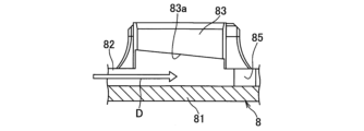
- FIG. 6 is a plan view showing a state after the base and the flange in FIG. 5 are assembled. 6 is a diagram for explaining an assembly structure of the base and the flange in FIG. 5 .
- the acoustic vibration device includes a frame fixed to a panel material, a vibration unit including a cylinder and a magnetic circuit unit attached to the inner periphery of the cylinder, a voice coil arranged in the magnetic gap of the magnetic circuit unit, a bobbin around which the voice coil is wound, a first damper connecting the cylinder and the bobbin, a second damper connecting the cylinder and the frame, and a drip-proof cover that prevents water droplets falling from above the panel material from adhering to the second damper, and the drip-proof cover is formed in a ring shape with an opening in the center, is attached to the vibration unit, and is arranged on the outer periphery of the magnetic circuit unit and above the second damper, and the upper part of the magnetic circuit unit is passed through the opening and arranged above the drip-proof cover.
- the drip-proof cover can prevent water droplets falling from above the panel material from adhering to the second damper.
- the drip-proof cover can prevent water droplets falling from above the panel material from adhering to the second damper.
- the drip-proof cover by forming the drip-proof cover into a ring shape with an opening in the center and attaching it to the vibration unit, it is possible to prevent the height dimension from becoming too large.
- the upper surface of the drip-proof cover is formed so that it slopes downward from the inner circumference to the outer circumference.
- the cylindrical body comprises a cylindrical portion and a flange portion extending outward from the lower end of the cylindrical portion, the outer periphery of the first damper is placed on the lower surface of the flange portion, the inner periphery of the second damper is placed on the upper surface of the flange portion, and the magnetic circuit portion and the drip-proof cover are attached to the cylindrical portion.
- This configuration can further prevent the height dimension from becoming large.
- FIGS 1 to 4 show an acoustic vibration device 1 according to one embodiment of the present invention.
- the acoustic vibration device 1 is disposed between a ceiling interior material (corresponding to a panel material) 501 and an exterior plate 502 of a vehicle, and outputs sound into the vehicle cabin by vibrating the ceiling interior material 501.
- the descriptions of the "up” and “down” directions are based on the state in which the acoustic vibration device 1 is disposed between the ceiling interior material 501 and the exterior panel 502 of the vehicle.
- the acoustic vibration device 1 includes a frame 11, a vibration unit 12, a voice coil assembly 5 in which a voice coil 52 is wound around a bobbin 51, a first damper 61, a second damper 62, a drip-proof cover 2, and a capacitor 93.
- the frame 11 includes a synthetic resin base 8 that is fixed to the ceiling interior material 501 via double-sided tape 91, and a synthetic resin flange 7 that is attached to the base 8.
- the base 8 includes a plate portion 81 that is placed on the ceiling interior material 501 via double-sided tape 91, a ring-shaped rib 82 formed on the upper surface of the plate portion 81, three claws 83 that are connected to the rib 82, a bolt fastening portion 84 that is connected to the outer periphery of the plate portion 81, and three protrusions 85 that protrude inward from the rib 82.
- the flange 7 includes an annular base 71 that is placed on the inside of the rib 82 and on the upper surface of the plate portion 81, a first damper mounting portion 74 that is connected to the base 71 and extends upward and inward, three protrusions 75 that protrude outward from the outer periphery of the base 71, an annular second damper mounting portion 72 that surrounds the base 71, a connecting portion 73 that connects the base 71 and the second damper mounting portion 72, a connector portion 76 that is connected to the outer periphery of the second damper mounting portion 72, a capacitor mounting portion 77, a bolt fastening portion 78, etc.
- the connector portion 76 connects the voice coil 52 to an external audio current supply source.
- the capacitor mounting portion 77 is where the capacitor 93 is mounted.
- the capacitor 93 is located between the audio current supply source and the voice coil 52.
- the above-mentioned base 8 and flange 7 are assembled together by rotating the flange 7 clockwise from the stacked state as shown in FIG. 5, so that each convex portion 75 of the flange 7 enters into the groove 83a of each claw 83 of the base 8 as shown in FIG. 6.
- the groove 83a of the claw 83 is formed so that it gradually narrows in width along the insertion direction (arrow D) of the convex portion 75. Therefore, as the flange 7 is rotated, the fit between the claw 83 and the convex portion 75 gradually tightens. When the flange 7 is further rotated, the convex portion 75 abuts against the convex portion 85.
- the flange 7 When repairing the acoustic vibration device 1, the flange 7 can be easily separated from the base 8 by removing the bolt 92 and turning the flange 7 counterclockwise.
- the vibration unit 12 comprises a cylindrical body 4 made of synthetic resin and a magnetic circuit unit 3 attached to the inner circumference of the cylindrical body 4.
- the cylindrical body 4 has a cylindrical portion 41, a flange portion 42 that extends outward from the lower end of the cylindrical portion 41, and a protruding portion 43 that protrudes from the inner peripheral surface of the cylindrical body 4.
- the magnetic circuit section 3 comprises a yoke 31 made of a magnetic material, a disk-shaped magnet 32, and a disk-shaped plate 33 made of a magnetic material.
- the yoke 31 comprises a disk-shaped overlapping portion 31a overlapping the magnet 32, and a cylindrical side wall 31b hanging down from the outer edge of the overlapping portion 31a.
- the magnet 32 is overlapped on the inside of the side wall 31b and on the underside of the overlapping portion 31a
- the plate 33 is overlapped on the inside of the side wall 31b and on the underside of the magnet 32.
- a magnetic gap is formed between the inner circumferential surface of the side wall 31b and the outer circumferential surface of the plate 33.
- the magnetic circuit section 3 is attached to the inner circumference of the cylindrical section 41 with the lower end of the side wall 31b of the yoke 31 abutting against the protruding section 43 of the cylindrical body 4.
- the voice coil assembly 5 is supported by the first damper 61, which is attached to the outer peripheral surface of the bobbin 51.
- the upper part of the bobbin 51 and the voice coil 52 are disposed within the magnetic gap of the magnetic circuit section 3.
- the first damper 61 is made of a material in which woven fabric is impregnated with resin, and is formed in a ring shape.
- the first damper 61 has an inner peripheral portion 61a bonded to the bobbin 51, an outer peripheral portion 61b superimposed on and bonded to the underside of the flange portion 42 of the cylindrical body 4, and a wavy portion 61c provided between the inner peripheral portion 61a and the outer peripheral portion 61b. In this way, the first damper 61 connects the inner peripheral side of the cylindrical body 4 and the bobbin 51.
- the first damper mounting portion 74 of the flange 7 is also bonded to the inner peripheral portion 61a of the first damper 61.
- the first damper mounting portion 74 of the flange 7 is also bonded to the outer peripheral surface of the bobbin 51.
- the second damper 62 is made of a material in which woven fabric is impregnated with resin, and is formed in a ring shape.
- the second damper 62 has an inner peripheral portion 62a that is superimposed and bonded to the upper surface of the flange portion 42 of the cylindrical body 4, an outer peripheral portion 62b that is superimposed and bonded to the second damper mounting portion 72 of the flange 7, and a curved portion 62c that is provided between the inner peripheral portion 62a and the outer peripheral portion 62b.
- the curved portion 62c is formed in a semicircular shape that bulges upward in cross section. In this way, the second damper 62 connects the outer peripheral side of the cylindrical body 4 and the flange 7.
- the second damper 62 is also positioned outside the first damper 61.
- the cylinder 4 is supported by both the first damper 61 arranged on its inner circumference and the second damper 62 arranged on its outer circumference.
- the drip-proof cover 2 is intended to prevent water droplets (condensation water) that have fallen from the outer panel 502 side from adhering to the second damper 62, and in this example is attached to the cylindrical body 4.
- the drip-proof cover 2 is made of synthetic resin and includes a cover body 21 and an attachment portion 22.
- the cover body 21 is formed in an annular shape with an opening in the center.
- the opening in the center of the cover body 21 is given the reference symbol 23.
- the attachment portion 22 is formed in a cylindrical shape and hangs down from the underside of the cover body 21 and the outer periphery of the opening 23.
- the attachment portion 22 is attached to the upper end and outer periphery of the cylindrical portion 41.
- Such a drip-proof cover 2 is disposed on the outer periphery side of the magnetic circuit section 3 and above the second damper 62.
- the upper part of the magnetic circuit section 3 is disposed above the drip-proof cover 2 through the opening 23.
- the upper surface of the cover body 21 is formed so as to have a downward slope from the inner periphery side to the outer periphery side. This allows water droplets adhering to the drip-proof cover 2 to be guided to the outer periphery side and dropped onto the ceiling interior material 501 side.
- the acoustic vibration device 1 is placed in the narrow space between the ceiling interior material 501 and the exterior panel 502 of the vehicle, and there were restrictions on the height dimension when providing the drip-proof cover 2.
- the drip-proof cover 2 is not a cover that covers the entire vibration unit 12, but rather has a minimal and simple structure to cover the second damper 62.
- the cover body 21 is formed into a ring shape with an opening in the center, and the drip-proof cover 2 is configured to have a height that does not exceed the top of the magnetic circuit unit 3 (overlapping portion 31a of the yoke 31), and this drip-proof cover 2 is attached to the cylindrical body 4.
- the cylindrical body 4 is composed of a cylindrical portion 41, a flange portion 42, and a protruding portion 43.
- the first damper 61 is attached to the underside of the flange portion 42
- the second damper 62 is attached to the upper surface of the flange portion 42
- the magnetic circuit portion 3 is attached to the inner periphery of the cylindrical portion 41
- the mounting portion 22 of the drip-proof cover 2 is attached to the outer periphery of the cylindrical portion 41.
- the cover body 21 by forming the cover body 21 into a ring shape with an opening in the center, the weight of the drip-proof cover 2 can be reduced. Also, by exposing the upper part of the magnetic circuit part 3 from the opening 23 of the cover body 21, heat dissipation can be improved.
- the electromagnetic force generated by supplying an audio current to the voice coil 52 is used as a driving force to vibrate the vibration unit 12, which then vibrates the ceiling interior material 501 via the frame 11, thereby outputting sound into the vehicle cabin.
- the vibration unit 12 includes a cylinder 4 and a magnetic circuit unit 3, but the vibration unit of the present invention may include a cylinder, a magnetic circuit unit, and other components.
- the drip-proof cover 2 is attached to the cylinder 4, but in the present invention, the drip-proof cover may be attached to the magnetic circuit unit, or may be attached to a component other than the cylinder and magnetic circuit unit.
- the acoustic vibration device 1 was attached to the ceiling interior material 501 of the vehicle, but the acoustic vibration device of the present invention can be attached not only to the ceiling interior material of the vehicle, but also to various panel materials that can output sound by vibrating them.
Landscapes
- Physics & Mathematics (AREA)
- Engineering & Computer Science (AREA)
- Acoustics & Sound (AREA)
- Signal Processing (AREA)
- Audible-Bandwidth Dynamoelectric Transducers Other Than Pickups (AREA)
- Fittings On The Vehicle Exterior For Carrying Loads, And Devices For Holding Or Mounting Articles (AREA)
Priority Applications (3)
| Application Number | Priority Date | Filing Date | Title |
|---|---|---|---|
| JP2025503228A JP7825775B2 (ja) | 2023-02-27 | 2023-02-27 | 音響用加振装置 |
| US19/135,312 US20260032367A1 (en) | 2023-02-27 | 2023-02-27 | Acoustic excitation device |
| PCT/JP2023/007004 WO2024180592A1 (ja) | 2023-02-27 | 2023-02-27 | 音響用加振装置 |
Applications Claiming Priority (1)
| Application Number | Priority Date | Filing Date | Title |
|---|---|---|---|
| PCT/JP2023/007004 WO2024180592A1 (ja) | 2023-02-27 | 2023-02-27 | 音響用加振装置 |
Publications (1)
| Publication Number | Publication Date |
|---|---|
| WO2024180592A1 true WO2024180592A1 (ja) | 2024-09-06 |
Family
ID=92589400
Family Applications (1)
| Application Number | Title | Priority Date | Filing Date |
|---|---|---|---|
| PCT/JP2023/007004 Ceased WO2024180592A1 (ja) | 2023-02-27 | 2023-02-27 | 音響用加振装置 |
Country Status (3)
| Country | Link |
|---|---|
| US (1) | US20260032367A1 (https=) |
| JP (1) | JP7825775B2 (https=) |
| WO (1) | WO2024180592A1 (https=) |
Citations (2)
| Publication number | Priority date | Publication date | Assignee | Title |
|---|---|---|---|---|
| JPS56145182U (https=) * | 1980-04-01 | 1981-11-02 | ||
| JP2021029005A (ja) * | 2019-08-09 | 2021-02-25 | アルパイン株式会社 | 音響用の加振装置及び車載音響装置 |
Family Cites Families (1)
| Publication number | Priority date | Publication date | Assignee | Title |
|---|---|---|---|---|
| JPS58114681U (ja) * | 1982-01-27 | 1983-08-05 | 松下電器産業株式会社 | 車載用スピ−カ |
-
2023
- 2023-02-27 WO PCT/JP2023/007004 patent/WO2024180592A1/ja not_active Ceased
- 2023-02-27 US US19/135,312 patent/US20260032367A1/en active Pending
- 2023-02-27 JP JP2025503228A patent/JP7825775B2/ja active Active
Patent Citations (2)
| Publication number | Priority date | Publication date | Assignee | Title |
|---|---|---|---|---|
| JPS56145182U (https=) * | 1980-04-01 | 1981-11-02 | ||
| JP2021029005A (ja) * | 2019-08-09 | 2021-02-25 | アルパイン株式会社 | 音響用の加振装置及び車載音響装置 |
Also Published As
| Publication number | Publication date |
|---|---|
| JP7825775B2 (ja) | 2026-03-06 |
| JPWO2024180592A1 (https=) | 2024-09-06 |
| US20260032367A1 (en) | 2026-01-29 |
Similar Documents
| Publication | Publication Date | Title |
|---|---|---|
| US10028061B2 (en) | Speaker surround structure for maximizing cone diameter | |
| EP2603017B1 (en) | Speaker | |
| WO2008127157A1 (en) | Damper | |
| CN101606396A (zh) | 电子发声器的振动膜和具有该振动膜的电子发声器 | |
| JPWO2010050056A1 (ja) | スピーカ用連結部材及びスピーカ | |
| US7325648B2 (en) | Frame for speaker device and speaker device | |
| JP7825775B2 (ja) | 音響用加振装置 | |
| US20050271241A1 (en) | Speaker device | |
| CN114760546B (zh) | 扬声器装置及车辆用车门 | |
| JP4723999B2 (ja) | スピーカ及びスピーカユニット | |
| JP2006229643A (ja) | スピーカ | |
| US20060188124A1 (en) | Frame for speaker device and speaker device | |
| JP7330623B2 (ja) | 音響用の加振装置及び車載音響装置 | |
| US20050271244A1 (en) | Resin frame, resin grille and speaker device | |
| US7377358B2 (en) | Frame for speaker device and speaker device | |
| US20050271238A1 (en) | Resin frame, speaker unit and speaker device | |
| JP2009027673A (ja) | スピーカ装置及びツィータユニット | |
| US20070223774A1 (en) | Coupled body of speaker apparatus | |
| JP2005277870A (ja) | スピーカー装置及びスピーカー装置の製造方法 | |
| KR101722527B1 (ko) | 박형 스피커 | |
| JP2008167137A (ja) | スピーカ | |
| WO2023190623A1 (ja) | 車両用電気音響変換器 | |
| JP2005184781A (ja) | スピーカ装置 | |
| JP7528658B2 (ja) | スピーカーシステム | |
| US20060237258A1 (en) | Frame for speaker device and speaker device |
Legal Events
| Date | Code | Title | Description |
|---|---|---|---|
| 121 | Ep: the epo has been informed by wipo that ep was designated in this application |
Ref document number: 23925150 Country of ref document: EP Kind code of ref document: A1 |
|
| WWE | Wipo information: entry into national phase |
Ref document number: 2025503228 Country of ref document: JP |
|
| NENP | Non-entry into the national phase |
Ref country code: DE |
|
| 122 | Ep: pct application non-entry in european phase |
Ref document number: 23925150 Country of ref document: EP Kind code of ref document: A1 |