WO2024177095A1 - 錯触力覚発生装置 - Google Patents
錯触力覚発生装置 Download PDFInfo
- Publication number
- WO2024177095A1 WO2024177095A1 PCT/JP2024/006167 JP2024006167W WO2024177095A1 WO 2024177095 A1 WO2024177095 A1 WO 2024177095A1 JP 2024006167 W JP2024006167 W JP 2024006167W WO 2024177095 A1 WO2024177095 A1 WO 2024177095A1
- Authority
- WO
- WIPO (PCT)
- Prior art keywords
- vibration generator
- vibration
- drive signal
- illusionary tactile
- tactile force
- Prior art date
- Legal status (The legal status is an assumption and is not a legal conclusion. Google has not performed a legal analysis and makes no representation as to the accuracy of the status listed.)
- Ceased
Links
Images







Classifications
-
- G—PHYSICS
- G06—COMPUTING OR CALCULATING; COUNTING
- G06F—ELECTRIC DIGITAL DATA PROCESSING
- G06F3/00—Input arrangements for transferring data to be processed into a form capable of being handled by the computer; Output arrangements for transferring data from processing unit to output unit, e.g. interface arrangements
- G06F3/01—Input arrangements or combined input and output arrangements for interaction between user and computer
- G06F3/011—Arrangements for interaction with the human body, e.g. for user immersion in virtual reality
- G06F3/014—Hand-worn input/output arrangements, e.g. data gloves
-
- G—PHYSICS
- G06—COMPUTING OR CALCULATING; COUNTING
- G06F—ELECTRIC DIGITAL DATA PROCESSING
- G06F3/00—Input arrangements for transferring data to be processed into a form capable of being handled by the computer; Output arrangements for transferring data from processing unit to output unit, e.g. interface arrangements
- G06F3/01—Input arrangements or combined input and output arrangements for interaction between user and computer
-
- G—PHYSICS
- G06—COMPUTING OR CALCULATING; COUNTING
- G06F—ELECTRIC DIGITAL DATA PROCESSING
- G06F3/00—Input arrangements for transferring data to be processed into a form capable of being handled by the computer; Output arrangements for transferring data from processing unit to output unit, e.g. interface arrangements
- G06F3/01—Input arrangements or combined input and output arrangements for interaction between user and computer
- G06F3/016—Input arrangements with force or tactile feedback as computer generated output to the user
Definitions
- the present invention relates to a technology that gives the wearer a haptic sensation (illusory tactile sensation).
- Patent Document 1 describes a haptic information presentation system.
- the haptic information presentation system of Patent Document 1 includes a housing that is held by the user.
- a vibrator is built into the housing. A part of the vibrator is exposed from the housing.
- the user receives a haptic sensation by touching the vibrating body while holding the housing.
- the object of the present invention is therefore to provide an illusionary tactile force generation device that can provide an illusionary tactile force while minimizing restrictions on the user's actions.
- the tactile illusionary force sense generating device of this invention is an illusionary force sense generating device that provides an illusionary force sense through the hand, and is equipped with a first vibration generator, a second vibration generator, a first wearing device, and a second wearing device.
- the first vibration generator generates a first vibration for generating the illusionary force sense.
- the second vibration generator generates a second vibration for generating the illusionary force sense.
- the first wearing device allows the first vibration generator to be worn on a first finger of the hand.
- the second wearing device allows the second vibration generator to be worn on a second finger of the hand.
- the first vibration generator, the first attachment, the second attachment, and the second vibration generator are arranged in the order of the direction in which the fingers of the hand are arranged.
- the first vibration generator and the second vibration generator that generate the haptic illusion can be worn on the side of the hand. This improves the freedom of the hand. Also, the distance between the first vibration generator and the second vibration generator is increased, and the haptic illusion provided is greater.
- the tactile illusionary force sense generating device of this invention is an illusionary force sense generating device that provides an illusionary tactile force sense through the hand, and is equipped with a first vibration generator, a second vibration generator, a first wearing device, a second wearing device, and a drive signal generating device.
- the first vibration generator generates a first vibration for generating the illusionary tactile force sense.
- the second vibration generator generates a second vibration for generating the illusionary tactile force sense.
- the first wearing device allows the first vibration generator to be worn on a first finger of the hand.
- the second wearing device allows the second vibration generator to be worn on a second finger of the hand.
- the drive signal generating unit generates a first drive signal for the first vibration and a second drive signal for the second vibration.
- the drive signal generating unit determines a combination of the waveform of the first drive signal and the waveform of the second drive signal based on the type of illusionary tactile sensation.
- the first vibration generator and the second vibration generator that generate the haptic illusion can be worn on the side of the hand. This improves the freedom of the hand.
- multiple types of haptic illusion can be generated by combining the waveforms of the first drive signal and the second drive signal.
- This invention makes it possible to provide the user with an illusionary tactile sensation while minimizing restrictions on the user's actions.
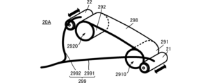
- FIG. 1 is a perspective view showing the appearance of a portion of the illusionary tactile force sense generating device according to the first embodiment that is worn on a hand.
- FIG. 2 is a four-sided view showing the illusionary tactile force sense generating device according to the first embodiment worn on a hand.
- FIG. 3 is a functional block diagram of the illusionary tactile force sense generating device according to the first embodiment.
- FIG. 4 is a table showing an example of the relationship between the combination of the first drive signal S1 and the second drive signal S2 and the type of illusionary tactile force.
- FIG. 5(A) is a diagram showing an image of the illusory tactile force sense of a hand moving forward, and FIG.
- FIG. 5(B) is a diagram showing an image of the illusory tactile force sense of a hand moving backward.
- FIG. 6(A) is a diagram showing an image of the illusory tactile force sensation of a right-handed rotation of a hand
- FIG. 6(B) is a diagram showing an image of the illusory tactile force sensation of a left-handed rotation of a hand.
- FIG. 7 is a perspective view showing the appearance of the portion of the illusionary tactile force sense generating device according to the second embodiment that is worn on the hand.
- Figure 8 (A) is an external oblique view showing the portion of the tactile force sense generating device of the third embodiment that is worn on the hand
- Figure 8 (B) is a functional block diagram of the tactile force sense generating device of the third embodiment
- Figure 8 (C) is a functional block diagram of a derived example of the tactile force sense generating device of the third embodiment.
- FIG. 9 is an external perspective view showing the portion of the illusionary tactile force sense generating device according to the fourth embodiment that is worn on the hand.
- FIG. 10 is a plan view of the illusionary tactile force sense generating device according to the fourth embodiment.
- FIG. 11 is a functional block diagram of the illusionary tactile force sense generating device according to the fourth embodiment.
- FIG. 12 is a table showing an example of the relationship between the combination of the third drive signal S3 and the fourth drive signal S4 and the type of illusionary tactile force.
- FIG. 13(A) is a diagram showing an image of the illusory tactile force sensation when twisting the hand to the left
- FIG. 13(B) is a diagram showing an image of the illusory tactile force sensation when twisting the hand to the right.
- FIG. 14 is an external perspective view showing a portion to be worn on a hand in a derivative example of the illusionary tactile force sense generating device according to the fourth embodiment.
- Figures 15(A), 15(B), 15(C), 15(D), 15(E), 15(F), and 15(G) are front views of illusionary tactile sense generating devices each having a different configuration of wearing equipment.
- FIG. 1 is a perspective view showing the appearance of a portion of the illusionary tactile force sense generating device according to the first embodiment that is worn on a hand.
- the illusionary tactile sense generating device 20 includes a vibration generator 21, a vibration generator 22, a mounting device 291, a mounting device 292, and a signal cable 299.
- the signal cable 299 includes a signal cable 2991 and a signal cable 2992.
- vibration generator 21 corresponds to the "first vibration generator” and vibration generator 22 corresponds to the “second vibration generator.”
- Mounting fixture 291 corresponds to the "first mounting fixture” and mounting fixture 292 corresponds to the “second mounting fixture.”
- Signal cable 2991 corresponds to the "first signal cable” and signal cable 2992 corresponds to the "second signal cable.”
- Vibration generator 21 and vibration generator 22 have the same configuration.
- the external shape of the vibration generator 21 is cylindrical, and has a first end E11 and a second end E12 in the direction in which the cylinder extends.
- the external shape of the vibration generator 22 is cylindrical, and has a first end E21 and a second end E22 in the direction in which the cylinder extends. Note that the external shape of the vibration generator 21 is not limited to a cylindrical shape.
- vibration generator 21 and vibration generator 22 each include a cylindrical housing, a magnet, a core material, and a coil.
- the magnet, core material, and coil are disposed inside the housing.
- the core material is held so that it can vibrate relative to the housing.
- the magnet is attached to the core material.
- the coil is disposed, for example, on the inner wall surface of the housing, and is disposed along the magnet.
- the coil of the vibration generator 21 is connected to a signal cable 2991.
- a first drive signal S1 is supplied to the coil of the vibration generator 21 through the signal cable 2991.
- the structure (first vibrating body) having the magnet and core material of the vibration generator 21 vibrates in parallel to the direction connecting the first end E11 and the second end E12 (the direction in which the cylinder extends (the axis of the first vibration)) due to the first drive signal S1.
- the housing of the vibration generator 21 vibrates, and the vibration generator 21 can apply vibrations to the outside.
- the coil of the vibration generator 22 is connected to a signal cable 2992.
- a second drive signal S2 is supplied to the coil of the vibration generator 22 through the signal cable 2992.
- the structure (second vibrating body) having the magnet and core material of the vibration generator 22 vibrates parallel to the direction connecting the first end E21 and the second end E22 (the direction in which the cylinder extends (the axis of the second vibration)) due to the second drive signal S2.
- the housing of the vibration generator 22 vibrates, and the vibration generator 22 can apply vibrations to the outside.
- Attachment 291 and attachment 292 have the same configuration. Attachment 291 and attachment 292 are made of a material capable of transmitting vibrations.
- the attachment 291 is a tubular body and has a through hole 2910.
- the attachment 292 is a tubular body and has a through hole 2920.
- the through holes 2910 and 2920 are large enough for a finger to pass through.
- the vibration generator 21 is fixed to the outer circumferential surface of the mounting fixture 291.
- the extension direction of the cylinder of the vibration generator 21 (the axis of the first vibration) and the extension direction of the tubular body of the mounting fixture 291 are parallel.
- the vibration generator 22 is fixed to the outer circumferential surface of the mounting fixture 292.
- the extension direction of the cylinder of the vibration generator 22 (axis of the second vibration) and the extension direction of the tubular body of the mounting fixture 292 are parallel.
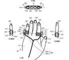
- FIG. 2 is a four-view diagram showing the state in which the illusionary tactile sense generating device according to the first embodiment is worn on the hand.
- Fig. 2 shows the state in which the device is worn on the left hand, and is a top view seen from the back of the hand, a right side view seen from the index finger side, a left side view seen from the little finger side, and a front view seen from the fingertip side.
- the attachment 291 is attached to the index finger 932 (e.g., corresponding to the first finger) of the hand 90.
- the index finger 932 is inserted through the through hole 2910 of the attachment 291.
- the inner surface of the attachment 291 is in close contact with the index finger 932 with a predetermined pressure being applied.
- the surface (the opening surface of the through hole 2910) perpendicular to the direction in which the index finger 932 is inserted into the attachment 291 is the attachment surface of the attachment 291.
- the vibration generator 21 is placed on the side 9321 of the index finger 932. More specifically, the vibration generator 21 is placed on the side 9321 of the index finger 932 opposite the side of the middle finger 933.
- the attachment 292 is attached to the little finger 935 (e.g., corresponding to the second finger) of the hand 90.
- the little finger 935 is inserted through the through hole 2920 of the attachment 292.
- the inner surface of the attachment 292 is in close contact with the little finger 935 with a predetermined pressure being applied.
- the surface perpendicular to the direction in which the little finger 935 is inserted into the attachment 292 is the attachment surface of the attachment 292.
- the vibration generator 22 is placed on the side 9351 of the little finger 935. More specifically, the vibration generator 22 is placed on the side 9351 of the little finger 935 opposite the side of the ring finger 934.
- the user to whom the illusionary tactile force sense is to be given can wear vibration generator 21 and vibration generator 22 without having to grasp them using the whole hand, etc.
- the illusionary tactile force sense generating device 20 can give the illusionary tactile force sense without reducing the freedom of use of the user's hand.
- the vibration generator 21, the vibration generator 22, the attachment 291, and the attachment 292 are arranged in the order of vibration generator 21, attachment 291, attachment 292, and vibration generator 22, from the index finger 932 toward the little finger 935.
- the vibration generator 21 and the vibration generator 22 are arranged on both ends sandwiched between the attachment 291 and the attachment 292.
- the vibration generators 21 and 22 are positioned at approximately both ends of the hand 90, excluding the thumb 931. This further reduces the reduction in the user's freedom of use of the hand.
- the tactile illusion generating device 20 can provide multiple types of tactile illusions, as described below, while minimizing restrictions on the user's actions.
- the vibration generators 21 and 22 are spaced apart by the width of the hand 90 excluding the thumb 931. Therefore, the vibration generators 21 and 22 are positioned as far apart as possible within the range of the size of the user's hand 90. This allows the illusionary tactile force to be imparted efficiently during the illusionary tactile force of rotation described below.
- the vibration generator 21 is positioned so that the first end E11 is at the tip side of the index finger 932 and the second end E12 is at the base side of the index finger 932 (the back of the hand 91 side).
- the vibration generator 22 is positioned so that the first end E21 is at the tip side of the little finger 935 and the second end E22 is at the base side of the little finger 935 (the back of the hand 91 side).
- this wearing mode positioning mode
- the positional relationship between both ends of vibration generator 21 and vibration generator 22 in the direction in which the finger extends can be corrected by the way in which first drive signal S1 and second drive signal S2 are provided. However, by determining the positional relationship between both ends of vibration generator 21 and vibration generator 22 in the direction in which the finger extends in this way in advance, it becomes easier to control the first drive signal S1 and the second drive signal S2.
- signal cable 2991 and signal cable 2992 are arranged along the back of the hand 91.
- by fixing or semi-fixing at least one of the wiring shape and length of signal cable 2991 and signal cable 2992 in advance it is possible to determine to some extent the positional relationship between the vibration generator 21, attachment device 291, attachment device 292, and vibration generator 22 described above before attaching them to the hand 90.
- FIG. 3 is a functional block diagram of the illusionary tactile force sense generating device according to the first embodiment.
- the tactile illusion generating device 20 includes a vibration generator 21, a vibration generator 22, an operation input unit 27, a drive signal generating unit 28, a signal cable 2991, and a signal cable 2992.
- the vibration generator 21 is connected to the drive signal generating unit 28 via a signal cable 2991.
- the vibration generator 22 is connected to the drive signal generating unit 28 via a signal cable 2992.
- the drive signal generating unit 28 is connected to the operation input unit 27.
- the operation input unit 27 accepts a selection input of the type of haptic illusion to be given to the user.
- the operation input unit 27 outputs the type of haptic illusion to the drive signal generation unit 28.
- the drive signal generating unit 28 generates a first drive signal S1 and a second drive signal S2 based on the type of haptic illusion.
- the first drive signal S1 and the second drive signal S2 are realized by adjusting the waveform, frequency, amplitude, etc. according to the type of haptic illusion.
- the drive signal generating unit 28 supplies the first drive signal S1 to the vibration generator 21 through a signal cable 2991.
- the drive signal generating unit 28 supplies the second drive signal S2 to the vibration generator 22 through a signal cable 2992. At this time, it is preferable that the drive signal generating unit 28 supplies (outputs) the first drive signal S1 and the second drive signal S2 in synchronization.
- the vibration generator 21 generates a vibration (first vibration) along the axis of the first vibration based on the first drive signal S1.
- the first vibration is propagated to the index finger 932 through the attachment 291.
- the illusionary tactile force sense generating device 20 gives the index finger 932 a first tactile force sense due to the first vibration.
- the vibration generator 22 generates a vibration (second vibration) along the axis of the second vibration based on the second drive signal S2.
- the second vibration is propagated to the little finger 935 through the attachment 292.
- the illusionary tactile force sense generating device 20 gives the little finger 935 a second tactile force sense due to the second vibration.
- the tactile illusion generating device 20 combines the first tactile sense with the second tactile sense to provide the user with the following various types of tactile illusions:
- FIG. 4 is a table showing an example of the relationship between the combination of the first drive signal S1 and the second drive signal S2 and the type of tactile force sense.
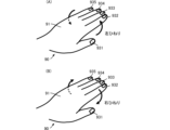
- FIG. 5(A) is a diagram showing an image of the tactile force sense of a forward movement of the hand
- FIG. 5(B) is a diagram showing an image of the tactile force sense of a backward movement of the hand.
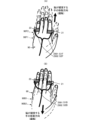
- FIG. 6(A) is a diagram showing an image of the tactile force sense of a right rotation of the hand
- FIG. 6(B) is a diagram showing an image of the tactile force sense of a left rotation of the hand.
- the illusory tactile force sensation of the hand moving forward is a illusory tactile force sensation that creates an illusion in the brain that the hand 90 is moving in the direction of the fingertips, even though the hand 90 is not actually moving.
- the haptic illusion of backward movement of the hand is a haptic illusion that creates an illusion in the brain that the hand 90 is moving toward the wrist (toward the base of the fingers) even though the hand 90 is not actually moving.
- the tactile force illusion of right rotation of the hand is a tactile force illusion that creates an illusion in the brain that the hand 90 is rotating right even though the hand 90 is not actually moving.
- the hand 90 is the left hand, so the tactile force illusion rotates in the direction of the thumb.
- the tactile force illusion of the hand rotating left is a tactile force illusion that creates an illusion in the brain that the hand 90 is rotating left, even though the hand 90 is not actually moving.
- the hand 90 is the left hand, so the tactile force illusion rotates in the direction of the little finger.
- the drive signal generating unit 28 selects the first drive signal S1F and the second drive signal S2F.
- the first drive signal S1F is a signal that generates vibrations that make the user feel as if the part (index finger 932) in contact with the vibration generator 21 is moving from the second end E12 side to the first end E11 side of the vibration generator 21.
- the second drive signal S2F is a signal that generates vibrations that make the user feel as if the part (little finger 935) in contact with the vibration generator 22 is moving from the second end E22 side to the first end E21 side of the vibration generator 22.
- the index finger 932 and the little finger 935 are given a force sensation that makes them move in the forward direction of the hand 90.
- a force sensation that makes the hand 90 move in the forward direction is synthesized in the hand 90, and the user gets the illusion that the hand 90 is moving in the forward direction, as shown by the hand 90, the hand 90F1, and the hand 90F2 in FIG. 5(A).
- the drive signal generating unit 28 selects the first drive signal S1B and the second drive signal S2B.
- the first drive signal S1B is a signal that generates vibrations that make the user feel as if the part in contact with the vibration generator 21 (index finger 932) is moving from the first end E11 side to the second end E12 side of the vibration generator 21.
- the second drive signal S2B is a signal that generates vibrations that make the user feel as if the part in contact with the vibration generator 22 (little finger 935) is moving from the first end E21 side to the second end E22 side of the vibration generator 22.
- the index finger 932 and the little finger 935 are given a force sensation that makes them move backwards in the hand 90.
- a force sensation that makes the hand 90 move backwards is synthesized in the hand 90, and the user gets the illusion that the hand 90 is moving forwards, as shown by the hand 90, the hand 90B1, and the hand 90B2 in FIG. 5(B).
- the drive signal generating unit 28 selects the first drive signal S1B and the second drive signal S2F.
- the index finger 932 is given a force sensation that moves the hand 90 backward
- the little finger 935 is given a force sensation that moves the hand 90 forward.
- the hand 90 receives a combination of a force sensation of the hand 90 moving backward on the index finger 932 side and a force sensation of the hand 90 moving forward on the little finger 935 side, and the user gets the illusion that the hand 90 is rotating to the right, as shown by hand 90, hand 90RR1, and hand 90RR2 in FIG. 6(A).
- the drive signal generating unit 28 selects the first drive signal S1F and the second drive signal S2B.
- the index finger 932 is given a force sensation that moves the hand 90 in a forward direction
- the little finger 935 is given a force sensation that moves the hand 90 in a backward direction.
- the hand 90 receives a combination of a force sensation of the hand 90 moving forward on the index finger 932 side and a force sensation of the hand 90 moving backward on the little finger 935 side, and the user gets the illusion that the hand 90 is rotating to the right, as shown by hand 90, hand 90RL1, and hand 90RL2 in FIG. 6(B).
- the illusionary tactile force sense generating device 20 can provide the user with multiple types of illusionary tactile force senses.
- the illusionary tactile force sense generating device 20 can efficiently provide a large illusionary tactile force sense without unnecessarily increasing the vibrations of the vibration generators 21 and 22.
- the illusionary tactile force sense generating device 20 can efficiently provide an illusionary tactile force sense of rotation.
- Fig. 7 is a perspective view showing the appearance of the part of the illusionary tactile force sense generating device according to the second embodiment that is worn on the hand.
- the illusionary force sense generating device 20A according to the second embodiment differs from the illusionary force sense generating device 20 according to the first embodiment in that it includes a connecting member 298.
- the other configuration of the illusionary force sense generating device 20A is similar to that of the illusionary force sense generating device 20, and a description of similar parts will be omitted.
- the illusionary tactile force sense generating device 20A includes a connecting member 298.
- the connecting member 298 connects to the mounting device 291 and the mounting device 292.
- the connecting member 298 is, for example, a flat membrane. It is preferable that the connecting member 298 is flexible and stretchable.
- the distance between the end where the connecting member 298 connects to the attachment 291 and the end where the connecting member 298 connects to the attachment 292 is preferably about the width of the hand 90.
- the tactile illusionary force sense generating device 20A provides the same effects as the tactile illusionary force sense generating device 20, while allowing the user to wear the tactile illusionary force sense generating device 20A more easily and reliably.
- the connecting member 298 be on the back of the hand 91 side, and for example, a mark indicating that it should be worn on the back of the hand 91 may be displayed.
- FIG. 8(A) is an external perspective view showing a part of the illusionary force sense generating device according to the third embodiment that is worn on the hand
- Fig. 8(B) is a functional block diagram of the illusionary force sense generating device according to the third embodiment
- Fig. 8(C) is a functional block diagram of a derived example of the illusionary force sense generating device according to the third embodiment.
- the illusionary force sense generating device 20B according to the third embodiment differs from the illusionary force sense generating device 20 according to the first embodiment in that the first drive signal S1 and the second drive signal S2 are transmitted wirelessly.
- the other configurations of the illusionary force sense generating device 20B are the same as those of the illusionary force sense generating device 20, and a description of similar parts will be omitted.
- the tactile illusion generating device 20B includes a vibration generator 21B, a vibration generator 22B, and an antenna 26.
- the vibration generator 21B includes the configuration of the vibration generator 21 and an antenna 219.
- the antenna 219 is connected to the coil of the vibration generator 21B.
- the vibration generator 22B includes the configuration of the vibration generator 22 and an antenna 229.
- the antenna 229 is connected to the coil of the vibration generator 22B.
- the drive signal generating unit 28 is connected to the antenna 26.
- the antenna 26 is capable of wireless communication with the antenna 219 and the antenna 229.
- the illusionary tactile force sense generating device 20B can achieve the same effect as the illusionary tactile force sense generating device 20 while further reducing the reduction in the freedom of movement of the hand.
- the tactile illusion generating device 20Bx includes a vibration generator 21Bx, a vibration generator 22Bx, a drive signal generating unit 281, a drive signal generating unit 282, an operation input unit 27, an antenna 26x, an antenna 219x, and an antenna 229x.
- the vibration generator 21Bx and the drive signal generating unit 281 are connected, for example, by a wire.
- the vibration generator 22Bx and the drive signal generating unit 282 are connected, for example, by a wire. This connection can also be made wireless.
- Antenna 219x is connected to drive signal generating unit 281.
- Antenna 229x is connected to drive signal generating unit 282.
- Antenna 26x is connected to operation input unit 27.
- the operation input unit 27 transmits a signal S1x representing the type of the received illusionary tactile force to the drive signal generation unit 281 via antennas 26x and 219x.
- the operation input unit 27 transmits a signal S2x representing the type of the received illusionary tactile force to the drive signal generation unit 282 via antennas 26x and 229x.
- the drive signal generating unit 281 generates a first drive signal S1 based on the received signal S1x and outputs it to the vibration generator 21Bx.
- the drive signal generating unit 282 generates a second drive signal S2 based on the received signal S2x and outputs it to the vibration generator 22Bx.
- the illusionary tactile force sense generating device 20Bx can achieve the same effect as the illusionary tactile force sense generating device 20B.
- FIG. 9 is an external perspective view showing a part of the illusionary force sense generating device according to the fourth embodiment that is worn on the hand.
- Fig. 10 is a plan view of the illusionary force sense generating device according to the fourth embodiment.
- Fig. 11 is a functional block diagram of the illusionary force sense generating device according to the fourth embodiment.
- the illusionary tactile force sense generating device 20C according to the fourth embodiment differs from the illusionary tactile force sense generating device 20 according to the first embodiment in that it generates vibrations along an orthogonal axis, whereas the illusionary tactile force sense generating device 20 according to the first embodiment generates vibrations along a single axis.
- the portion of the illusionary force sense generating device 20C that is worn on the hand further includes a vibration generator 23, a vibration generator 24, and a signal cable 299V in addition to the illusionary force sense generating device 20.
- the signal cable 299H shown in Figs. 9 and 10 is the same as the signal cable 299 shown in the first embodiment.
- Vibration generator 23 and vibration generator 24 have the same configuration as vibration generator 21 and vibration generator 22.
- Vibration generator 23 has a first end E31 and a second end E32.
- Vibration generator 24 has a first end E41 and a second end E42.
- Vibration generator 23 corresponds to the "third vibration generator” and vibration generator 24 corresponds to the "fourth vibration generator.”
- the vibration generator 23 is attached to the mounting fixture 291 together with the vibration generator 21. More specifically, the vibration generator 21 is attached to the mounting fixture 291, and the vibration generator 23 is physically connected to the vibration generator 21.
- the direction in which the cylinder of vibration generator 23 extends (the direction connecting first end E31 and second end E32) is perpendicular to the direction in which the cylinder of vibration generator 21 extends (the direction connecting first end E11 and second end E12).
- the orthogonal angle here is not limited to being orthogonal (perfectly orthogonal).
- the orthogonal angle may have an error (fitting error) within a range that can generate an illusionary tactile sensation, as described below.
- the vibration direction of vibration generator 23 (axis of third vibration) is perpendicular to the vibration direction of vibration generator 21 (axis of first vibration) and the direction in which the fingers are arranged (axis Axa).
- the vibration generator 24 is attached to the mounting fixture 292 together with the vibration generator 22. More specifically, the vibration generator 22 is attached to the mounting fixture 292, and the vibration generator 24 is physically connected to the vibration generator 22.
- the direction in which the cylinder of the vibration generator 24 extends (the direction connecting the first end E41 and the second end E42) is perpendicular to the direction in which the cylinder of the vibration generator 22 extends (the direction connecting the first end E21 and the second end E22).
- the orthogonal angle here is not limited to being orthogonal (perfectly orthogonal).
- the orthogonal angle may have an error (fitting error) within a range that can generate an illusionary tactile sensation, as described below.
- the vibration direction of vibration generator 24 (axis of the fourth vibration) is perpendicular to the vibration direction of vibration generator 22 (axis of the second vibration) and the direction in which the fingers are aligned (axis Axa).
- Signal cable 299V includes signal cable 2993 and signal cable 2994.
- Signal cable 2993 is connected to vibration generator 23, and signal cable 2994 is connected to vibration generator 24.
- Signal cables 2993 and 2994 are arranged along the back of the hand 91 together with signal cables 2991 and 2992.
- the electrical functions of the illusionary force sense generating device 20C include vibration generators 23, 24, signal cables 2993 and 2994 in addition to those of the illusionary force sense generating device 20, and a drive signal generating unit 28C.
- the drive signal generating unit 28C differs from the drive signal generating unit 28 of the illusionary force sense generating device 20 in that it further generates a third drive signal S3 and a fourth drive signal S4.
- the vibration generator 23 and the drive signal generating unit 28C are connected via a signal cable 2993.
- the vibration generator 24 and the drive signal generating unit 28C are connected via a signal cable 2994.
- the drive signal generating unit 28C generates a third drive signal S3 and a fourth drive signal S4 based on the type of haptic illusion.
- the third drive signal S3 and the fourth drive signal S4 are realized by adjusting the waveform, frequency, amplitude, etc. according to the type of haptic illusion.
- the drive signal generating unit 28C supplies the third drive signal S3 to the vibration generator 23 through the signal cable 2993.
- the drive signal generating unit 28C supplies the fourth drive signal S4 to the vibration generator 24 through the signal cable 2994. At this time, it is preferable that the drive signal generating unit 28 supplies (outputs) the third drive signal S3 and the fourth drive signal S4 in synchronization.
- the vibration generator 23 generates a vibration (third vibration) along the axis of the third vibration based on the third drive signal S3.
- the third vibration is propagated to the index finger 932 through the attachment 291.
- the illusionary tactile force sense generating device 20C gives the index finger 932 a third tactile force sense due to the third vibration.
- the vibration generator 24 generates a vibration (fourth vibration) along the axis of the fourth vibration based on the fourth drive signal S4.
- the fourth vibration is propagated to the little finger 935 through the attachment 292.
- the illusionary tactile force sense generating device 20C gives a fourth tactile force sense to the little finger 935 by the fourth vibration.
- the tactile illusion generating device 20C combines the third tactile sense with the fourth tactile sense to provide the user with the following various types of tactile illusion:
- FIG. 12 is a table showing an example of the relationship between the combination of the third drive signal S3 and the fourth drive signal S4 and the type of tactile force sensation.
- FIG. 13(A) is a diagram showing an image of the tactile force sensation of twisting the hand to the left
- FIG. 13(B) is a diagram showing an image of the tactile force sensation of twisting the hand to the right.
- the tactile force illusion of twisting the hand to the left is a tactile force illusion that creates an illusion in the brain that the hand 90 is twisting counterclockwise (the thumb 931 is rotating toward the back of the hand 91 and the little finger 935 is rotating toward the palm) even though the hand 90 is not actually moving.
- the right-twisting tactile force illusion is a tactile force illusion that creates an illusion in the brain that the hand 90 is twisting clockwise (the little finger 935 rotates toward the back of the hand 91 and the thumb 931 rotates toward the palm) even though the hand 90 is not actually moving.
- the drive signal generating unit 28C selects the third drive signal S3F and the fourth drive signal S4B.
- the third drive signal S3F is a signal that generates vibrations that make the user feel as if the part in contact with the vibration generator 23 (the index finger 932) is moving from the second end E32 side to the first end E31 side of the vibration generator 23.
- the fourth drive signal S4B is a signal that generates vibrations that make the user feel as if the part in contact with the vibration generator 24 (the little finger 935) is moving from the first end E41 side to the second end E42 side of the vibration generator 24.
- the drive signal generating unit 28C selects the third drive signal S3B and the fourth drive signal S4F.
- the third drive signal S3B is a signal that generates vibrations that make the user feel as if the part (index finger 932) in contact with the vibration generator 23 is moving from the first end E31 side to the second end E32 side of the vibration generator 23.
- the fourth drive signal S4F is a signal that generates vibrations that make the user feel as if the part (little finger 935) in contact with the vibration generator 24 is moving from the second end E42 side to the first end E41 side of the vibration generator 24.
- the tactile illusion generating device 20C can give the user the illusion of twisting the hand 90, as well as the illusion of moving the hand 90 back and forth and rotating the hand 90.
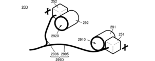
- FIG. 14 is an external perspective view showing a portion to be worn on a hand in a derivative example of the illusionary force sense generating device according to the fourth embodiment.
- the derivative example of the illusionary force sense generating device 20D differs from the illusionary force sense generating device 20C according to the fourth embodiment in that it includes a vibration generator 251, a vibration generator 252, and a signal cable 299D.
- the vibration generator 251 has a configuration in which the first vibrating body of the vibration generator 21 and the third vibrating body of the vibration generator 23 in the illusionary tactile force sense generating device 20C are built into a single housing (first housing).
- the vibration generator 252 has a configuration in which the second vibrating body of the vibration generator 22 and the fourth vibrating body of the vibration generator 24 in the illusionary tactile force sense generating device 20C are built into a single housing (second housing).
- Vibration generator 251 is attached to mounting fixture 291.
- Vibration generator 252 is attached to mounting fixture 292.
- Signal cable 299D includes signal cable 2995 and signal cable 2996.
- Signal cable 2995 is a cable that bundles together signal cable 2991 and signal cable 2993 in illusionary tactile force sense generating device 20C.
- Signal cable 2996 is a cable that bundles together signal cable 2992 and signal cable 2994 in illusionary tactile force sense generating device 20C.
- Signal cable 2995 is connected to vibration generator 251 and also to drive signal generating unit 28C (not shown).
- Signal cable 2996 is connected to vibration generator 252 and also to drive signal generating unit 28C (not shown).
- the illusionary tactile force sense generating device 20D can achieve the same effect as the illusionary tactile force sense generating device 20C.
- FIG. 15(A) includes a wearing device 291X1 and a wearing device 292X1.
- the wearing device 291X1 and the wearing device 292X1 are made of a flexible, stretchable tubular body.
- the illusionary tactile force sense generating device 20X2 in FIG. 15 (B) includes a wearing device 291X2 and a wearing device 292X2.
- the wearing device 291X2 and the wearing device 292X2 are composed of a flexible and stretchable tubular body.
- the wearing device 291X2 includes a tongue-shaped adjustment member 2919.
- the adjustment member 2919 corresponds to the "first adjustment member.”
- the adjustment member 2919 can be wrapped around the outer peripheral surface of the tubular body.
- the illusionary tactile force sense generating device 20X2 can adjust the strength of the wearing device 291X2 on the index finger 932 depending on the state in which the adjustment member 2919 is wrapped around the tubular body.
- the wearing device 292X2 includes a tongue-shaped adjustment member 2929.
- the adjustment member 2929 corresponds to the "second adjustment member.”
- the adjustment member 2929 can be wrapped around the outer peripheral surface of the tubular body.
- the illusionary tactile force sense generating device 20X2 can adjust the strength with which the wearing device 292X2 is attached to the little finger 935 by winding the adjustment member 2929 around the tubular body.
- the illusionary tactile force sense generating device 20X3 in FIG. 15(C) includes a wearing device 291X3 and a wearing device 292X3.
- the wearing devices 291X3 and 292X3 are flexible flat membranes, and preferably have stretchability.
- the wearing device 291X3 is wrapped around the index finger 932.
- the wearing device 291X3 has a fixing means at the portion that overlaps when wrapped around.
- the wearing device 292X3 is wrapped around the little finger 935.
- the wearing device 292X3 has a fixing means at the portion that overlaps when wrapped around.
- the illusionary tactile force sense generating device 20X4 in FIG. 15(D) includes a mounting device 291X4 and a mounting device 292X4.
- the mounting device 291X4 and the mounting device 292X4 are cylindrical tubular bodies with a circumferential notch.
- the illusionary tactile sense generating device 20X5 in FIG. 15(E) includes a mounting device 291X5 and a mounting device 292X5.
- the mounting device 291X5 and the mounting device 292X5 are rectangular tubular bodies with a circumferential notch.
- the illusionary tactile force sense generating device 20X6 of Figure 15 (F) comprises a wearing device 291X6 and a wearing device 292X6.
- the wearing device 291X6 comprises a fixed portion 2911 and a shape variable portion 2912.
- the fixed portion 2911 and the shape variable portion 2912 are connected to form a single tubular body.
- the fixed portion 2911 is made of a material with high vibration transmission efficiency.
- the vibration generator 21 is fixed to the fixed portion 2911.
- the shape variable portion 2912 is made of a material that is flexible and stretchable.
- the wearing device 291X6 comprises a fixed portion 2921 and a shape variable portion 2922.
- the fixed portion 2921 and the shape variable portion 2922 are connected to form a single tubular body.
- the fixed portion 2921 is made of a material with high vibration transmission efficiency.
- the vibration generator 22 is fixed to the fixed portion 2921.
- the shape-variable section 2922 is made of a flexible and stretchable material.
- the illusionary tactile force sense generating device 20X7 in FIG. 15(G) includes a wearing device 291X7 and a wearing device 292X7.
- the wearing devices 291X7 and 292X7 are made of a material that has low flexibility, such as metal or resin, and is capable of transmitting vibrations with high efficiency.
- the wearing devices 291X7 and 292X7 have different sizes of through holes.
- the wearing devices 291X7 and 292X7 are formed according to the shape of the fingers on which they are to be worn. In this example, the wearing device 291X7 is formed according to the shape of the index finger 932, and the wearing device 292X7 is formed according to the shape of the little finger 935.
- a one-axis or two-axis vibration generator is used, but the above configuration can also be applied to a three-axis vibration generator.
- the vibration generator is attached to the index finger and little finger, but the same effect can be achieved by attaching a vibration generator to each of two different fingers.
- An illusionary tactile force sense generating device that gives an illusionary tactile force sense through a hand, A first vibration generator that generates a first vibration for generating the illusionary tactile force; A second vibration generator that generates a second vibration for generating the illusionary tactile force; a first wearing tool for wearing the first vibration generator on a first finger of the hand; A second wearing tool for wearing the second vibration generator on a second finger of the hand; Equipped with An illusionary tactile force sense generating device, in which the first vibration generator, the first wearing device, the second wearing device, and the second vibration generator are arranged in the order of the direction in which the fingers of the hand are arranged.
- ⁇ 3> The illusionary tactile sensation generating device of ⁇ 1> or ⁇ 2>, in which the direction perpendicular to the mounting surface of the first mounting device and the direction perpendicular to the mounting surface of the second mounting device are parallel.
- the first vibration generator includes a first vibrating body
- the second vibration generator includes a second vibrating body
- ⁇ 6> A first signal cable connected to the first vibration generator and transmitting a first drive signal that generates the first vibration, and a second signal cable connected to the second vibration generator and transmitting a second drive signal that generates the second vibration,
- An illusionary tactile sense generating device according to any of ⁇ 1> to ⁇ 5>, wherein the length of the first signal cable and the length of the second signal cable are determined based on the placement distance between the first vibration generator and the second vibration generator.
- ⁇ 8> An illusionary tactile sense generating device according to any one of ⁇ 1> to ⁇ 7>, wherein the first attachment has a first adjustment member capable of adjusting the strength of attachment to the first finger, and the second attachment has a second adjustment member capable of adjusting the strength of attachment to the second finger.
- ⁇ 9> The illusionary tactile sense generating device according to any one of ⁇ 1> to ⁇ 8>, wherein the first attachment is attached to the index finger and the second attachment is attached to the little finger.
- a third vibration generator that generates a third vibration for generating the illusionary tactile force
- a fourth vibration generator that generates a fourth vibration for generating the illusionary tactile force
- Equipped with The third vibration generator is attached to the first attachment
- the fourth vibration generator is attached to the second attachment,
- the vibration axis of the third vibration generator and the vibration axis of the first vibration generator are perpendicular to each other,
- An illusionary tactile sense generating device according to any one of ⁇ 1> to ⁇ 10>, wherein the axis of vibration of the fourth vibration generator and the axis of vibration of the second vibration generator are perpendicular to each other.
- the vibration axis of the third vibration generator is perpendicular to the extension direction of the first finger
- the first vibration generator and the third vibration generator are separate and physically connected to each other,
- a first vibrating body of the first vibration generator and a third vibrating body of the third vibration generator are built into a common first housing,
- An illusionary tactile force sense generating device that gives an illusionary tactile force sense through a hand, A first vibration generator that generates a first vibration for generating the illusionary tactile force; A second vibration generator that generates a second vibration for generating the illusionary tactile force; a first wearing tool for wearing the first vibration generator on a first finger of the hand; A second wearing tool for wearing the second vibration generator on a second finger of the hand; a drive signal generating unit that generates a first drive signal for the first vibration and a second drive signal for the second vibration; Equipped with The drive signal generating unit An illusionary tactile force generating device that determines a combination of the waveform of the first drive signal and the waveform of the second drive signal based on the type of the illusionary tactile force.
- ⁇ 17> The illusionary tactile sensation generating device of ⁇ 15> or ⁇ 16>, in which the direction perpendicular to the mounting surface of the first mounting device and the direction perpendicular to the mounting surface of the second mounting device are parallel.
- the first vibration generator includes a first vibrating body
- the second vibration generator includes a second vibrating body
- the illusionary tactile sense generating device according to any one of ⁇ 15> to ⁇ 17>, wherein the first vibrating body and the second vibrating body are arranged in parallel.
- ⁇ 20> The illusionary tactile force generating device according to any one of ⁇ 15> to ⁇ 19>, wherein the drive signal generating unit generates, as the first drive signal and the second drive signal, a signal of a first waveform that gives a first illusionary tactile force sensation that the hand moves toward the fingertip.
- ⁇ 21> The illusionary tactile force generating device according to any one of ⁇ 15> to ⁇ 20>, wherein the drive signal generating unit generates, as the first drive signal and the second drive signal, a signal of a second waveform that gives a second illusionary tactile force sensation in which the hand moves toward the wrist.
- the drive signal generating unit The tactile illusion force generating device of any of ⁇ 15> to ⁇ 21>, which generates, as the first drive signal, a signal of a first waveform that gives a first tactile illusion force sense of the hand moving toward the fingertip, and generates, as the second drive signal, a signal of a second waveform that gives a second tactile illusion force sense of the hand moving toward the wrist.
- the drive signal generating unit A tactile illusion force generating device according to any one of ⁇ 15> to ⁇ 22>, which generates, as the first drive signal, a signal of a second waveform that gives a second tactile illusion force sense in which the hand moves toward the wrist, and generates, as the second drive signal, a signal of a first waveform that gives a first tactile illusion force sense in which the hand moves toward the fingertip.
- a third vibration generator that generates a third vibration for generating the illusionary tactile force sense and is attached to the first wearing device together with the first vibration generator;
- a fourth vibration generator that generates a fourth vibration for generating the illusionary tactile force sense and is attached to the second wearing device together with the second vibration generator; Equipped with The drive signal generating unit generating a third drive signal for the third vibration and a fourth drive signal for the fourth vibration;
- the drive signal generating unit As the third drive signal, a signal having a waveform that imparts an illusionary tactile force sensation moving toward the back of the hand or a signal having a waveform that imparts an illusionary tactile force sensation moving toward the palm of the hand is generated; As the fourth drive signal, a signal having a waveform that imparts an illusionary tactile force sensation moving toward the back of the hand or a signal having a waveform that imparts an illusionary tactile force sensation moving toward the palm of the hand is generated;
Landscapes
- Engineering & Computer Science (AREA)
- General Engineering & Computer Science (AREA)
- Theoretical Computer Science (AREA)
- Human Computer Interaction (AREA)
- Physics & Mathematics (AREA)
- General Physics & Mathematics (AREA)
- User Interface Of Digital Computer (AREA)
Priority Applications (3)
| Application Number | Priority Date | Filing Date | Title |
|---|---|---|---|
| JP2025502762A JPWO2024177095A1 (https=) | 2023-02-23 | 2024-02-21 | |
| CN202480013982.XA CN120731416A (zh) | 2023-02-23 | 2024-02-21 | 伪触觉产生装置 |
| US19/305,183 US20250370543A1 (en) | 2023-02-23 | 2025-08-20 | Pseudo-haptic sensation generation apparatus |
Applications Claiming Priority (4)
| Application Number | Priority Date | Filing Date | Title |
|---|---|---|---|
| JP2023-026793 | 2023-02-23 | ||
| JP2023026793 | 2023-02-23 | ||
| JP2023109167 | 2023-07-03 | ||
| JP2023-109167 | 2023-07-03 |
Related Child Applications (1)
| Application Number | Title | Priority Date | Filing Date |
|---|---|---|---|
| US19/305,183 Continuation US20250370543A1 (en) | 2023-02-23 | 2025-08-20 | Pseudo-haptic sensation generation apparatus |
Publications (1)
| Publication Number | Publication Date |
|---|---|
| WO2024177095A1 true WO2024177095A1 (ja) | 2024-08-29 |
Family
ID=92500870
Family Applications (1)
| Application Number | Title | Priority Date | Filing Date |
|---|---|---|---|
| PCT/JP2024/006167 Ceased WO2024177095A1 (ja) | 2023-02-23 | 2024-02-21 | 錯触力覚発生装置 |
Country Status (4)
| Country | Link |
|---|---|
| US (1) | US20250370543A1 (https=) |
| JP (1) | JPWO2024177095A1 (https=) |
| CN (1) | CN120731416A (https=) |
| WO (1) | WO2024177095A1 (https=) |
Citations (7)
| Publication number | Priority date | Publication date | Assignee | Title |
|---|---|---|---|---|
| JP2005190465A (ja) * | 2003-11-20 | 2005-07-14 | National Institute Of Advanced Industrial & Technology | 触力覚情報提示システムおよび方法 |
| WO2016088246A1 (ja) * | 2014-12-05 | 2016-06-09 | 富士通株式会社 | 触感提供システム、及び、触感提供装置 |
| JP2017073101A (ja) * | 2015-10-05 | 2017-04-13 | 株式会社ミライセンス | 触力覚情報提示システム |
| WO2017175868A1 (ja) * | 2016-04-07 | 2017-10-12 | 国立研究開発法人科学技術振興機構 | 触覚情報変換装置、触覚情報変換方法、および、触覚情報変換プログラム、並びに、素子配置構造体 |
| US10082875B1 (en) * | 2017-06-05 | 2018-09-25 | Korea Institute Of Science And Technology | Vibrating apparatus, system and method for generating tactile stimulation |
| JP2019139470A (ja) * | 2018-02-09 | 2019-08-22 | 日本電信電話株式会社 | 擬似力覚発生装置 |
| JP2019191862A (ja) * | 2018-04-24 | 2019-10-31 | 株式会社デンソー | カーファインダシステム |
-
2024
- 2024-02-21 CN CN202480013982.XA patent/CN120731416A/zh active Pending
- 2024-02-21 WO PCT/JP2024/006167 patent/WO2024177095A1/ja not_active Ceased
- 2024-02-21 JP JP2025502762A patent/JPWO2024177095A1/ja active Pending
-
2025
- 2025-08-20 US US19/305,183 patent/US20250370543A1/en active Pending
Patent Citations (7)
| Publication number | Priority date | Publication date | Assignee | Title |
|---|---|---|---|---|
| JP2005190465A (ja) * | 2003-11-20 | 2005-07-14 | National Institute Of Advanced Industrial & Technology | 触力覚情報提示システムおよび方法 |
| WO2016088246A1 (ja) * | 2014-12-05 | 2016-06-09 | 富士通株式会社 | 触感提供システム、及び、触感提供装置 |
| JP2017073101A (ja) * | 2015-10-05 | 2017-04-13 | 株式会社ミライセンス | 触力覚情報提示システム |
| WO2017175868A1 (ja) * | 2016-04-07 | 2017-10-12 | 国立研究開発法人科学技術振興機構 | 触覚情報変換装置、触覚情報変換方法、および、触覚情報変換プログラム、並びに、素子配置構造体 |
| US10082875B1 (en) * | 2017-06-05 | 2018-09-25 | Korea Institute Of Science And Technology | Vibrating apparatus, system and method for generating tactile stimulation |
| JP2019139470A (ja) * | 2018-02-09 | 2019-08-22 | 日本電信電話株式会社 | 擬似力覚発生装置 |
| JP2019191862A (ja) * | 2018-04-24 | 2019-10-31 | 株式会社デンソー | カーファインダシステム |
Also Published As
| Publication number | Publication date |
|---|---|
| US20250370543A1 (en) | 2025-12-04 |
| JPWO2024177095A1 (https=) | 2024-08-29 |
| CN120731416A (zh) | 2025-09-30 |
Similar Documents
| Publication | Publication Date | Title |
|---|---|---|
| US9299230B2 (en) | Modular exoskeletal force feedback controller | |
| US20220362927A1 (en) | Motion assist device | |
| KR102200556B1 (ko) | 촉각자극 제공 장치 | |
| JP5900887B2 (ja) | 耳穴装着型骨伝導装置 | |
| JP6996510B2 (ja) | 力覚提示装置 | |
| KR20150048685A (ko) | 실시간 진동 피드백을 제공하는 휴대단말용 보호케이스 | |
| JP2010524551A (ja) | 電気機械マッサージ装置及び着用可能マッサージ装置 | |
| EP2802155A1 (en) | Neckband-type earphone | |
| WO2013172250A1 (ja) | 頭部装着型表示装置 | |
| WO2024177095A1 (ja) | 錯触力覚発生装置 | |
| JP2005081538A (ja) | マニピュレータおよびこれを備えた装置 | |
| CN112867979B (zh) | 触觉呈现装置和触觉呈现控制方法 | |
| WO2025104986A1 (ja) | 錯触力覚発生装置 | |
| JP2017004240A (ja) | 方向提示装置 | |
| JP2017033335A (ja) | 牽引力発生装置 | |
| WO2020235364A1 (ja) | 触覚提示装置、キャリブレーション方法及びプログラム | |
| JPWO2024177095A5 (https=) | ||
| JP7401992B2 (ja) | 力覚提示装置 | |
| WO2024214741A1 (ja) | 錯力覚提示装置 | |
| US20240346896A1 (en) | Haptic device | |
| JP2011129064A (ja) | コントローラ | |
| US20260024920A1 (en) | Systems and methods for integrating antennas into textile bands | |
| JP2008271054A (ja) | 身体装着型ディスプレイ | |
| JP2025135678A (ja) | 力触覚情報伝達装置 | |
| JP2014124547A (ja) | 振動装置 |
Legal Events
| Date | Code | Title | Description |
|---|---|---|---|
| 121 | Ep: the epo has been informed by wipo that ep was designated in this application |
Ref document number: 24760393 Country of ref document: EP Kind code of ref document: A1 |
|
| ENP | Entry into the national phase |
Ref document number: 2025502762 Country of ref document: JP Kind code of ref document: A |
|
| WWE | Wipo information: entry into national phase |
Ref document number: 2025502762 Country of ref document: JP |
|
| WWE | Wipo information: entry into national phase |
Ref document number: 202480013982.X Country of ref document: CN |
|
| NENP | Non-entry into the national phase |
Ref country code: DE |
|
| WWP | Wipo information: published in national office |
Ref document number: 202480013982.X Country of ref document: CN |
|
| 122 | Ep: pct application non-entry in european phase |
Ref document number: 24760393 Country of ref document: EP Kind code of ref document: A1 |