WO2024176705A1 - 情報処理装置、プログラム、情報処理方法 - Google Patents
情報処理装置、プログラム、情報処理方法 Download PDFInfo
- Publication number
- WO2024176705A1 WO2024176705A1 PCT/JP2024/002168 JP2024002168W WO2024176705A1 WO 2024176705 A1 WO2024176705 A1 WO 2024176705A1 JP 2024002168 W JP2024002168 W JP 2024002168W WO 2024176705 A1 WO2024176705 A1 WO 2024176705A1
- Authority
- WO
- WIPO (PCT)
- Prior art keywords
- image
- distance
- area
- information
- control unit
- Prior art date
- Legal status (The legal status is an assumption and is not a legal conclusion. Google has not performed a legal analysis and makes no representation as to the accuracy of the status listed.)
- Ceased
Links
Images














Classifications
-
- G—PHYSICS
- G01—MEASURING; TESTING
- G01S—RADIO DIRECTION-FINDING; RADIO NAVIGATION; DETERMINING DISTANCE OR VELOCITY BY USE OF RADIO WAVES; LOCATING OR PRESENCE-DETECTING BY USE OF THE REFLECTION OR RERADIATION OF RADIO WAVES; ANALOGOUS ARRANGEMENTS USING OTHER WAVES
- G01S17/00—Systems using the reflection or reradiation of electromagnetic waves other than radio waves, e.g. lidar systems
- G01S17/86—Combinations of lidar systems with systems other than lidar, radar or sonar, e.g. with direction finders
-
- G—PHYSICS
- G01—MEASURING; TESTING
- G01S—RADIO DIRECTION-FINDING; RADIO NAVIGATION; DETERMINING DISTANCE OR VELOCITY BY USE OF RADIO WAVES; LOCATING OR PRESENCE-DETECTING BY USE OF THE REFLECTION OR RERADIATION OF RADIO WAVES; ANALOGOUS ARRANGEMENTS USING OTHER WAVES
- G01S17/00—Systems using the reflection or reradiation of electromagnetic waves other than radio waves, e.g. lidar systems
- G01S17/88—Lidar systems specially adapted for specific applications
- G01S17/89—Lidar systems specially adapted for specific applications for mapping or imaging
-
- G—PHYSICS
- G01—MEASURING; TESTING
- G01S—RADIO DIRECTION-FINDING; RADIO NAVIGATION; DETERMINING DISTANCE OR VELOCITY BY USE OF RADIO WAVES; LOCATING OR PRESENCE-DETECTING BY USE OF THE REFLECTION OR RERADIATION OF RADIO WAVES; ANALOGOUS ARRANGEMENTS USING OTHER WAVES
- G01S7/00—Details of systems according to groups G01S13/00, G01S15/00, G01S17/00
- G01S7/48—Details of systems according to groups G01S13/00, G01S15/00, G01S17/00 of systems according to group G01S17/00
- G01S7/51—Display arrangements
-
- G—PHYSICS
- G06—COMPUTING OR CALCULATING; COUNTING
- G06F—ELECTRIC DIGITAL DATA PROCESSING
- G06F3/00—Input arrangements for transferring data to be processed into a form capable of being handled by the computer; Output arrangements for transferring data from processing unit to output unit, e.g. interface arrangements
- G06F3/01—Input arrangements or combined input and output arrangements for interaction between user and computer
- G06F3/048—Interaction techniques based on graphical user interfaces [GUI]
- G06F3/0484—Interaction techniques based on graphical user interfaces [GUI] for the control of specific functions or operations, e.g. selecting or manipulating an object, an image or a displayed text element, setting a parameter value or selecting a range
-
- G—PHYSICS
- G09—EDUCATION; CRYPTOGRAPHY; DISPLAY; ADVERTISING; SEALS
- G09G—ARRANGEMENTS OR CIRCUITS FOR CONTROL OF INDICATING DEVICES USING STATIC MEANS TO PRESENT VARIABLE INFORMATION
- G09G5/00—Control arrangements or circuits for visual indicators common to cathode-ray tube indicators and other visual indicators
-
- G—PHYSICS
- G09—EDUCATION; CRYPTOGRAPHY; DISPLAY; ADVERTISING; SEALS
- G09G—ARRANGEMENTS OR CIRCUITS FOR CONTROL OF INDICATING DEVICES USING STATIC MEANS TO PRESENT VARIABLE INFORMATION
- G09G5/00—Control arrangements or circuits for visual indicators common to cathode-ray tube indicators and other visual indicators
- G09G5/02—Control arrangements or circuits for visual indicators common to cathode-ray tube indicators and other visual indicators characterised by the way in which colour is displayed
-
- G—PHYSICS
- G09—EDUCATION; CRYPTOGRAPHY; DISPLAY; ADVERTISING; SEALS
- G09G—ARRANGEMENTS OR CIRCUITS FOR CONTROL OF INDICATING DEVICES USING STATIC MEANS TO PRESENT VARIABLE INFORMATION
- G09G5/00—Control arrangements or circuits for visual indicators common to cathode-ray tube indicators and other visual indicators
- G09G5/08—Cursor circuits
-
- G—PHYSICS
- G09—EDUCATION; CRYPTOGRAPHY; DISPLAY; ADVERTISING; SEALS
- G09G—ARRANGEMENTS OR CIRCUITS FOR CONTROL OF INDICATING DEVICES USING STATIC MEANS TO PRESENT VARIABLE INFORMATION
- G09G5/00—Control arrangements or circuits for visual indicators common to cathode-ray tube indicators and other visual indicators
- G09G5/14—Display of multiple viewports
-
- G—PHYSICS
- G09—EDUCATION; CRYPTOGRAPHY; DISPLAY; ADVERTISING; SEALS
- G09G—ARRANGEMENTS OR CIRCUITS FOR CONTROL OF INDICATING DEVICES USING STATIC MEANS TO PRESENT VARIABLE INFORMATION
- G09G5/00—Control arrangements or circuits for visual indicators common to cathode-ray tube indicators and other visual indicators
- G09G5/36—Control arrangements or circuits for visual indicators common to cathode-ray tube indicators and other visual indicators characterised by the display of a graphic pattern, e.g. using an all-points-addressable [APA] memory
-
- G—PHYSICS
- G09—EDUCATION; CRYPTOGRAPHY; DISPLAY; ADVERTISING; SEALS
- G09G—ARRANGEMENTS OR CIRCUITS FOR CONTROL OF INDICATING DEVICES USING STATIC MEANS TO PRESENT VARIABLE INFORMATION
- G09G5/00—Control arrangements or circuits for visual indicators common to cathode-ray tube indicators and other visual indicators
- G09G5/36—Control arrangements or circuits for visual indicators common to cathode-ray tube indicators and other visual indicators characterised by the display of a graphic pattern, e.g. using an all-points-addressable [APA] memory
- G09G5/37—Details of the operation on graphic patterns
- G09G5/377—Details of the operation on graphic patterns for mixing or overlaying two or more graphic patterns
-
- G—PHYSICS
- G09—EDUCATION; CRYPTOGRAPHY; DISPLAY; ADVERTISING; SEALS
- G09G—ARRANGEMENTS OR CIRCUITS FOR CONTROL OF INDICATING DEVICES USING STATIC MEANS TO PRESENT VARIABLE INFORMATION
- G09G5/00—Control arrangements or circuits for visual indicators common to cathode-ray tube indicators and other visual indicators
- G09G5/36—Control arrangements or circuits for visual indicators common to cathode-ray tube indicators and other visual indicators characterised by the display of a graphic pattern, e.g. using an all-points-addressable [APA] memory
- G09G5/38—Control arrangements or circuits for visual indicators common to cathode-ray tube indicators and other visual indicators characterised by the display of a graphic pattern, e.g. using an all-points-addressable [APA] memory with means for controlling the display position
Definitions
- This technology relates to an information processing device, program, and information processing method that controls the display of distance information acquired by a distance measuring sensor.
- Japanese Patent Application Laid-Open No. 2003-233693 discloses a technique for suppressing loss of height information and reducing deterioration in accuracy when generating a two-dimensional grayscale image based on distance information.
- Patent Document 1 when it is desired to emphasize the distance in an area containing a fine pattern or the like in a grayscale image of distance information, it is difficult to identify the location of the pattern from the grayscale image, making the work difficult.
- This technology was developed in light of these circumstances, and aims to provide an environment in which distance information can be easily confirmed when developing distance measuring sensors, etc.
- An information processing device related to the present technology is equipped with a display control unit that displays a superimposed image in a first area on a display unit, in which a luminance image generated based on luminance information about reflected light from a subject is superimposed with distance information to the subject, and the superimposed position of the distance information on the luminance image is set to the position on the luminance image for the subject from which the distance information was obtained.
- the luminance image is, for example, a color image such as an RGB image, a monochrome image, etc.
- the distance information may be superimposed by superimposing characters or an image. This makes it easy to grasp at a glance the correspondence between the luminance image and the distance information.
- FIG. 1 is a block diagram illustrating an example of the configuration of an information processing system.
- 2 is a schematic diagram showing an example of the configuration of a light emitting unit included in the distance measuring camera; 1 is a schematic diagram for explaining a light receiving area that receives reflected light from a light emitting unit in a distance measuring sensor included in a distance measuring camera.
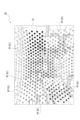
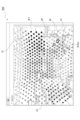
- FIG. 13 is a diagram showing an example of a superimposed image.
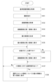
- FIG. 13 is a diagram showing the flow of distance information correction processing together with simple illustrations.
- FIG. 13 is a diagram showing an example of a first screen.
- 13A and 13B are diagrams showing a display state of the second area of the first screen when the control button is pressed.
- FIG. 10 is a flowchart showing a flow of a process executed by a control unit regarding display of the first screen.
- FIG. 13 is a diagram showing an example of a second screen. 13 is a flowchart showing a flow of a process executed by a control unit regarding display of the second screen.
- FIG. 13 is a diagram showing an example of a third screen. 13 is a flow chart showing a flow of a process executed by a control unit regarding the display of the 3rd screen.
- FIG. 13 is a diagram showing another example of the third screen. 13 is a flow chart showing a flow of processes executed by a control section regarding display of another example of the 3rd screen.
- FIG. 13 is a diagram showing an example of a fourth screen.
- FIG. 13 is a diagram showing an example of a fourth screen.
- FIG. 13 is an enlarged view of a fifth region in the fourth screen.
- FIG. 13 is a diagram showing a state in which a plurality of light receiving regions are selected in the individual selection field on the fourth screen.
- FIG. 13 is a diagram for explaining a state in which an icon image near the cursor is automatically selected on the superimposed image of the fourth screen.
- FIG. 13 is a diagram for explaining a state in which a plurality of icon images near the cursor are automatically selected on the superimposed image of the fourth screen.
- FIG. 13 is a diagram showing a state in which histograms are enlarged and displayed in the histogram area of the fourth screen, and shows a state in which a plurality of histograms are selected.
- 13 is a diagram showing a state in which a light-receiving region is highlighted in an individual selection field on the fourth screen in response to a selected histogram.
- 13 is a flow chart showing a flow of a process executed by a control unit regarding display of the fourth screen.
- 13 is a flowchart showing an example of a process for selecting and displaying an icon image and displaying a histogram relating to the icon image.
- 13 is a flowchart showing another example of the process of selecting and displaying an icon image and displaying a histogram related to the icon image.
- FIG. 13 is a diagram showing another example of a histogram animation.
- FIG. 13 is a diagram showing an example of a selection area set by a user.
- 13A and 13B are diagrams showing how icon images with large changes in distance information within a selection region are automatically selected.
- 13 is a flow chart showing a flow of a process executed by a control unit regarding display of the fifth screen. 13 is a flowchart for explaining that an automatic selection process in a selected area is performed after the start of an animation.
- FIG. 1 shows an example of the configuration of an information processing system S including an information processing device 1 according to an embodiment of the present technology.
- the information processing system S includes an information processing device 1, a camera system 2, a signal processing device 3, and a display device M.
- the camera system 2 includes multiple camera devices 4.
- the camera system 2 includes an RGB camera 4A that outputs an imaging signal for generating a color image as a luminance image, and a distance measuring camera 4B that outputs an imaging signal according to the distance to the subject.
- the RGB camera 4A is configured with an RGB sensor 4Aa in which pixels sensitive to R (red), G (green), and B (blue) light are arranged two-dimensionally, and optical components such as a lens group (not shown).
- RGB camera 4A is one aspect of a camera device for generating a luminance image. Another aspect of RGB camera 4A may be a camera device having color filters other than RGB, such as color filters sensitive to Cy (cyan), Mg (magenta), or Ye (yellow) light. Also, in addition to a camera device that captures color images, a camera device that captures monochrome images may be used instead of RGB camera 4A.
- the distance measurement camera 4B is configured with a distance measurement sensor 4Ba in which distance measurement pixels are arranged two-dimensionally to measure the distance to the subject for each pixel.
- the distance measurement camera 4B may perform distance measurement using the ToF (Time of Flight) method, or the distance measurement camera 4B may perform distance measurement using the image plane phase difference method.
- ToF Time of Flight
- the distance measurement is performed using the ToF method, and more specifically, a distance measurement camera 4B that performs distance measurement using the dToF (direct ToF) method is used as an example.
- dToF direct ToF
- the distance measuring camera 4B is equipped with a light emitting unit 4Bb in addition to a distance measuring sensor 4Ba.
- Optical components such as a lens group (not shown) are arranged on the subject side of the distance measuring sensor 4Ba and the light emitting unit 4Bb.
- the light-emitting unit 4Bb has a configuration in which light-emitting elements L, such as LEDs (Light Emitting Diodes), are arranged two-dimensionally. Each light-emitting element L is capable of emitting, for example, infrared light.
- LEDs Light Emitting Diodes
- the light-emitting unit 4Bb has a configuration in which 24 light-emitting elements L are two-dimensionally arranged in both the horizontal and vertical directions.
- one light-emitting element L is surrounded by six adjacent light-emitting elements L.
- the structure is such that light-emitting elements L are arranged at each intersection of the honeycomb structure.
- a light-emitting element L arranged in the nth row and the mth column is referred to as a light-emitting element L(n, m).
- the variables n and m are integers ranging from 0 to 23. That is, the light-emitting section 4Bb is configured to have a total of 576 light-emitting elements L from the light-emitting element L (0, 0) located at the upper left to the light-emitting element L (23, 23) located at the lower right.
- the distance measurement sensor 4Ba of the distance measurement camera 4B is configured by two-dimensionally arranging SPAD (Single Photon Avalanche Diode) elements as distance measurement pixels.
- SPAD Single Photon Avalanche Diode
- Each SPAD element has sensitivity only to infrared light corresponding to the light-emitting element L. Therefore, the SPAD element mainly receives infrared light irradiated from the light-emitting element L and reflected by the subject.
- FIG. 3 shows a schematic diagram of a light receiving region ArR that receives infrared light irradiated by each light emitting element L of the light emitting section 4Bb.
- the light receiving regions ArR can be provided in the same number as the light emitting elements L. However, when the infrared light passes outside the range of the distance measuring sensor 4Ba, the light receiving regions ArR are smaller than the light emitting elements L.
- the light receiving area ArR in the nth row and mth column is designated as the light receiving area ArR(m,n)
- a maximum of 576 light receiving areas ArR will be generated from the upper left light receiving area ArR(0,0) to the lower right light receiving area ArR(23,23).
- the light receiving area ArR corresponding to the light emitting element L(0,0) may be the light receiving area ArR(0,0), the light receiving area ArR(0,23), the light receiving area ArR(23,0), or the light receiving area ArR(23,23). That is, the correspondence between the light emitting element L and the light receiving area ArR may differ depending on the configuration of the optical components provided in the distance measuring camera 4B.
- One light receiving region ArR may include one pixel (SPAD element) or multiple pixels.
- the RGB camera 4A outputs an imaging signal for generating a color luminance image to the signal processing device 3 at the downstream stage. Further, the distance measuring camera 4B outputs an imaging signal for generating a distance image to the signal processing device 3 at the downstream side.
- the signal processing device 3 includes a control unit 5, a camera control unit 6, a luminance image generating unit 7, and a distance image generating unit 8.
- the control unit 5 causes the camera control unit 6, the brightness image generating unit 7, and the distance image generating unit 8 to execute predetermined processing in response to instructions from the information processing device 1.
- the camera control unit 6 causes the RGB camera 4A and distance measuring camera 4B of the camera system 2 to perform imaging operations, thereby causing each camera to output an imaging signal.
- the luminance image generating unit 7 performs various signal processing such as demosaic processing and various correction processes on the image signal output from the RGB camera 4A to generate a luminance image G1 as a color image.
- the luminance image generating unit 7 supplies the generated luminance image G1 to the information processing device 1.
- the distance image generator 8 generates a histogram using multiple image capture signals output from the distance measuring camera 4B, and generates distance information DI to the subject for each light receiving area ArR (or for each pixel) using the time difference between light emission and light reception, the speed of light, etc.
- the distance image generating unit 8 supplies information that associates this distance information DI with each light receiving region ArR to the information processing device 1 as a distance image G2.
- the information processing device 1 includes a control unit 9 and an operation unit 10 .
- the control unit 9 transmits various commands to the signal processing device 3 to realize generation of each image in the signal processing device 3.
- the control unit 9 also controls the camera system 2 via the signal processing device 3.
- the control unit 9 includes a display image generating unit 11 and a display control unit 12 .
- the display image generating unit 11 has a function of generating images to be displayed on the display unit Ma of the display device M.
- the images generated by the display image generating unit 11 include a superimposed image G3 in which distance information DI is superimposed on a luminance image G1.
- the superimposed image G3 will be described later.
- the display control unit 12 has a function of displaying various images such as the distance image G2 and the superimposed image G3 generated by the display image generating unit 11, and GUIs as various applications on the display unit Ma of the display device M.
- the information processing system S in this example is a system used for development and manufacturing inspection of the distance measuring sensor 4Ba provided in the distance measuring camera 4B. That is, the information processing system S is a system that is used by a user to check the accuracy of the distance information DI generated by the distance measurement sensor 4Ba.
- the user can efficiently carry out development work on the distance measuring sensor 4Ba, etc.
- the operation unit 10 is implemented as various operation means such as a mouse, a keyboard, or a touch panel that are operated by a user of the information processing device 1 .
- the superimposed image G3 is obtained by superimposing distance information DI on the luminance image G1 generated by the luminance image generating unit 7.
- the superimposed image G3 is obtained by superimposing distance information DI calculated in accordance with the light reception results in each light receiving region ArR of the distance measurement sensor 4Ba on the luminance image G1.
- each distance information DI is realized, for example, by superimposing an icon image PF with a display color according to the measured distance.
- the icon image PF is expressed in shades of black and white instead of changing its display color according to the distance.
- the distance information DI is displayed as a large circular icon image PF so that it is easy to see on the drawing.
- a smaller circular icon image PF than that in FIG. 4 may be superimposed on the brightness image G1 so that the brightness image G1 portion in the superimposed image G3 is easy to see.
- the distance information DI is expressed by the display color of the icon image PF, but the distance information DI may be expressed by the size of the icon image PF. For example, the shorter (closer) the distance is, the larger the size of the icon image PF may be.
- various other modes are possible, such as expressing the distance information DI by the degree of transparency of the icon image PF.
- the position at which the distance information DI is superimposed is determined based on the position of the subject.
- the display image generating unit 11 executes a process for calculating the superimposition position of the distance information DI on the luminance image G1, thereby generating a superimposed image G3 in which the distance information DI is superimposed at an appropriate position on the luminance image G1.
- the display image generating unit 11 performs a process of converting the position of the light receiving area ArR on the distance measuring sensor 4Ba that receives the reflected light from the subject into a superimposition position on the luminance image G1.
- This process is referred to as a distance information correction process.
- distance information before correction processing is referred to as pre-processing distance information DIa.
- FIG. 5 shows an outline of the flow of distance information correction processing.
- the display image generating unit 11 first performs a correction process on the pre-processing distance information DIa, which is distance information before correction, based on the position and size of the light-receiving region ArR (step S1).
- a histogram is generated based on individual distance information (here, unit distance information) obtained for each emission of the light-emitting element L corresponding to the light-receiving region ArR to be processed.
- the display image generating unit 11 performs an offset correction process using the information on the light emission timing (step S2).
- an offset time which is the time from the measurement start timing to the actual light emission timing of the light-emitting element L, is subtracted from the distance information calculated based on the time difference from the measurement start timing to the reflected light reception timing.
- the peak value of the histogram generated from each unit distance information is determined as the representative distance information for the light receiving region ArR.
- the display image generating unit 11 performs a distortion correction process on the representative distance information to remove lens distortion caused by a lens group provided on the subject side of the distance measuring sensor 4Ba (step S3).
- the display image generating unit 11 performs an rZ conversion process (step S4).
- the rZ conversion process the distance r between the light receiving area ArR of the distance measuring sensor 4Ba and the subject is converted into a distance Z between a plane including the distance measuring sensor 4Ba and a plane parallel to the plane including the subject.
- the viewpoint conversion process is a conversion that takes into account the difference in position between the distance measuring sensor 4Ba and the RGB sensor 4Aa, and determines the imaging position and distance of the subject in the RGB sensor 4Aa.
- the processing of step S5 is a process of finding the corresponding point of the light receiving area ArR of the distance measuring sensor 4Ba on the RGB sensor 4Aa, and further converting the above-mentioned distance Z into the distance between the surface including the RGB sensor 4Aa and the surface including the subject.
- the display image generating unit 11 By performing such processing, the superimposition position on the luminance image G1 and the distance information DI after the correction processing are calculated. Furthermore, the display image generating unit 11 generates a superimposed image G3 shown in FIG. 5 by superimposing the distance information DI at the superimposition position on the luminance image G1.
- FIG. 6 shows a first example of a screen displayed on the display unit Ma.
- the first screen 100 displayed on the display unit Ma is made up of three areas: a first area Ar1, a second area Ar2, and a third area Ar3.
- Each area is, for example, a window-type area, and can be moved or resized.
- the regions may be arranged so as not to overlap each other, or may be arranged so that a portion of each region overlaps with each other by enlarging and reducing the window.
- the first area Ar1 is an area in which the superimposed image G3 is displayed.
- Each icon image PF (distance information DI) superimposed on the superimposed image G3 in the first area Ar1 can be the target of a selection operation by the user.
- the second area Ar2 includes a first tab TB1 ("Depth” in the figure) and a second tab TB2 ("SPAD" in the figure).
- Fig. 6 shows a state in which the first tab TB1 is selected, and a distance image G2 and a legend 101 are displayed.
- the distance image G2 is composed of rectangular small areas ArS arranged in a matrix.
- Each small area ArS corresponds to a light receiving area ArR, and the display color of the small area ArS is based on the distance information DI for the light receiving area ArR. For example, the display color of the light receiving area ArR and the display color of the corresponding icon image PF are the same color.
- the legend 101 shows the correspondence between the display color of the small area ArS and the distance information.
- the memory values written next to the legend 101 represent the distance information in mm.
- the second area Ar2 displays RAW data output from the SPAD pixels serving as distance measurement pixels of the distance measurement sensor 4Ba (not shown).
- the third area Ar3 is an area in which information about the distance information DI is displayed.
- a user selects an icon image PF or a small area ArS in the distance image G2 superimposed on the superimposed image G3 by a selection operation, various information regarding the distance information DI linked to the selected icon image PF or small area ArS is displayed in the third area Ar3.
- the third area Ar3 multiple pieces of distance information DI can be displayed. Each time the user selects an icon image PF or a small area ArS, a selection ID (Identification) is assigned.
- one record is displayed for each selected ID.
- a record with the selected ID "pix_0" is displayed.
- Each record contains coordinate information ("x", "y” in the figure) indicating a position on the superimposed image G3 (or the luminance image G1), a serial ID ("DP" in the figure) assigned to each piece of distance information DI, and the distance information DI ("depth” in the figure).
- the serial ID is an ID that is assigned to each piece of distance information DI from distance information DI(0,0) to distance information DI(23,23) without duplication.
- the distance information DI is expressed as a number in the unit "mm".
- the selection ID string ("pix_0" in the figure) is used as an operation button, and when it is the target of a user click operation, the record is deleted from the third area Ar3.
- the third area Ar3 includes an all clear button 102 that deletes all records.
- a control button 103 ("control" in the figure) is disposed above the legend 101.
- a color change button 104 for changing the relationship between distance and color in the legend 101
- a lower limit input field 105 and an upper limit input field 106 for determining the upper and lower limit values of the legend 101
- a display change operation field 107 for changing the display method of the legend 101
- an automatic button 108 are displayed in the second area Ar2.
- the legend 101 and distance image G2 that were displayed before the control button 103 was pressed are displayed.
- the user can increase the efficiency of debugging operations by increasing the number of colors assigned to distances that the user wishes to check in detail out of the distance information DI. For example, by inputting "3000" in the lower limit input field 105 and "3500" in the upper limit input field 106, the display mode can be changed to one (non-linear display) that makes it easier to see the difference in distance information DI for subjects located between 3 m and 3.5 m. That is, the user can change the correspondence between the distance information DI and the display color.
- the AUTO button 108 is provided both before (FIG. 6) and after (FIG. 7) the control button 103 is pressed.
- the AUTO button 108 is an operator for returning the correspondence between the distance information DI in the legend 101 and the display color to a linear display mode (linear display). That is, the automatic button 108 is an operator that changes the display mode so that the display color changes linearly between the minimum distance information DI and the maximum distance information DI contained in the distance image G2.
- FIG. 8 an example of the processing executed by the control unit 9 of the information processing device 1 is shown in FIG. 8. Note that the processing shown in FIG. 8 shows only a part of the processing executed by each part of the control unit 9, and the control unit 9 also executes processing to detect operations performed by the user and processing corresponding to user operations.
- step S101 the control unit 9 issues an instruction to the camera system 2 to capture an image. This causes the RGB camera 4A and distance measuring camera 4B included in the camera system 2 to perform an image capture operation.
- step S102 the control unit 9 requests the signal processing device 3 to obtain distance information and luminance information.
- the signal processing device 3 generates a luminance image G1 based on the imaging signal output from the RGB camera 4A, and generates a distance image G2 based on the imaging signal output from the distance measuring camera 4B.
- step S103 the display control unit 12 of the control unit 9 displays the distance image G2 in the second area Ar2. As a result, the distance image G2 is displayed on the display unit Ma of the display device M.
- the display image generating unit 11 of the control unit 9 performs a correction process on the pre-processing distance information DIa in step S104 (see FIG. 5). This causes the corrected distance information DI and its superimposition position to be calculated.
- step S105 the display image generating unit 11 of the control unit 9 generates a superimposed image G3 by superimposing the distance information DI on the luminance image G1.
- the display control unit 12 of the control unit 9 displays the superimposed image G3 in the first area Ar1 in step S106. As a result, the distance image G2 and the superimposed image G3 are displayed on the display unit Ma of the display device M (see FIG. 6).
- step S107 the control unit 9 determines whether or not a selection operation has been performed on the distance information DI. If a selection operation has not been detected, the control unit 9 avoids the processing of step S108.
- step S107 if it is determined in step S107 that a selection operation has been detected, the process proceeds to step S108, and the display control unit 12 of the control unit 9 executes a process of displaying the selected distance information DI in the third area Ar3. As a result, detailed information about the distance information DI is displayed on the display unit Ma of the display device M, in addition to the distance image G2 and superimposed image G3.
- step S109 determines in step S109 whether or not an operation to change the display mode of the distance and display color has been detected. If it is determined that an operation to change the display mode has not been detected, the control unit 9 returns to the processing in step S107 without executing the processing in step S110.
- the display control unit 12 of the control unit 9 performs display control in step S110 so as to provide a display mode according to the change operation, thereby changing, for example, the display color of the small area ArS in the distance image G2 displayed in the second area Ar2.
- the display color of the icon image PF superimposed on the superimposed image G3 displayed in the first area Ar1 is also changed in the same way.
- step S110 After completing the process of step S110, the control unit 9 returns to the process of step S107.
- FIG. 1 A second example of the screen displayed on the display unit Ma is shown in FIG.
- a second screen 200 displayed on the display unit Ma is made up of a first area Ar1, a second area Ar2, and a third area Ar3.
- a switching button 201 is arranged on the second screen 200.
- the first area Ar1 displays the distance image G2 in the first example, which is obtained by the distance measuring camera 4B of the camera device 4 performing an imaging operation in accordance with instructions from the control unit 9.
- the second area Ar2 displays a difference image G5 generated based on the distance image G2 and the reference image G4.
- the reference image G4 is a distance image generated based on accurate distance information DI.
- the accurate distance information DI is distance information DI about the RGB camera 4A and the subject that should be obtained by capturing an image using the distance measuring camera 4B of the camera system 2 and correcting the unprocessed distance information DIa described above.
- the distance information in the reference image G4 is referred to as reference distance information DIb.
- the difference image G5 is an image generated based on the difference between the distance information DI for each light receiving region ArR in the distance image G2 and the reference distance information DIb for each light receiving region ArR in the reference image G4.
- the distance image G2, the reference image G4, and the difference image G5 are each composed of the same number of small regions ArS.
- the user can check the difference image G5 displayed in the second area Ar2 to determine whether the manufacturing error of the distance measurement sensor 4Ba is within the acceptable range. This allows the shipping decision of the distance measurement sensor 4Ba to be made appropriately.
- the user can check the correctness of the design of the distance measurement sensor 4Ba and areas for improvement by checking the difference image G5 displayed in the second area Ar2.
- the image displayed in the first area Ar1 and the image displayed in the second area Ar2 may be switched.
- a legend may also be displayed in the second region Ar2.
- the third area Ar3 multiple pieces of difference information can be displayed. Each time the user selects a small area ArS in the distance image G2 of the first area Ar1 or a small area ArS in the difference image G5 of the second area Ar2, a selection ID is assigned.
- the third area Ar3 displays one record for each selection ID.
- a record with the selection ID "pix_0" is displayed.
- Each record includes coordinate information ("x", "y” in the figure) indicating the position of the selected small area ArS on the distance image G2 (or difference image G5), distance information DI for the small area ArS ("depth1” in the figure), reference distance information DIb ("depth2” in the figure), and difference information therebetween ("def” in the figure).
- the coordinate information is represented by integer values from 0 to 23.
- the distance information DI, the reference distance information DIb, and the difference information are expressed as numbers in the unit "mm.”
- the character string of the selected ID in the third area Ar3 serves as an operation button for deleting the record, similar to the first example.
- the third area Ar3 is also provided with an all clear button 202 for deleting all records.
- the switch button 201 is an operator for switching the image displayed in the second area Ar2 between the difference image G5 and the distance image G2. For example, while the switch button 201 is pressed, the distance image G2 is displayed in the second area Ar2, and while the switch button 201 is not pressed, the difference image G5 is displayed in the second area Ar2.
- the user can compare the difference image G5 and the distance image G2, which are displayed in the same area in a time-division manner, and can easily confirm which small area ArS in the distance image G2 corresponds to the small area ArS with the largest difference in the difference image G5.
- the distance image G2 may be displayed in the second area Ar2, and the image displayed in the first area Ar1 may be switched from the distance image G2 to the reference image G4 or the difference image G5.
- a separate operator may be provided on the second screen 200 to switch the image displayed in the first area Ar1 between the distance image G2 and the reference image G4.
- FIG. 10 An example of the process executed by the control unit 9 of the information processing device 1 in this example is shown in Fig. 10. Note that the process shown in Fig. 10 shows a part of the process executed by each unit of the control unit 9, and the control unit 9 also executes a process for detecting an operation performed by a user and a process corresponding to the user operation. Moreover, the same processes as those shown in FIG. 8 are given the same step numbers and the description thereof will be omitted as appropriate.
- step S131 the control unit 9 acquires the reference distance information DIb.
- the reference distance information DIb acquired here is used to generate the difference image G5, and for example, the reference distance information DIb is acquired for each small area ArS of the difference image G5.
- step S101 the control unit 9 issues a shooting instruction to the camera system 2.
- step S132 the control unit 9 requests the signal processing device 3 to obtain distance information.
- the signal processing device 3 generates a distance image G2 based on the imaging signal output from the distance measuring camera 4B.
- the display control unit 12 of the control unit 9 displays the distance image G2 in the first area Ar1 in step S133.
- step S134 the display image generating unit 11 of the control unit 9 generates a difference image G5 from the distance image G2 and the reference image G4.
- the display control unit 12 of the control unit 9 displays the difference image G5 in the second area Ar2 in step S135.
- step S136 the control unit 9 determines whether the switching button 201 is being pressed. If it is determined that the switching button 201 is being pressed, the display control unit 12 of the control unit 9 causes the distance image G2 to be displayed in the second area Ar2 in step S103.
- control unit 9 proceeds to step S137 while keeping the difference image G5 displayed in the second area Ar2.
- step S137 the control unit 9 determines whether or not a selection operation has been performed on the small area ArS. If it is determined that a selection operation has been performed, the display control unit 12 of the control unit 9 causes the difference information for the selected small area ArS to be displayed in the third area Ar3 in step S138.
- step S138 After completing the process of step S138, or after determining in step S137 that a selection operation has not been performed on the small area ArS, the control unit 9 returns to the process of step S136.
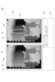
- FIG. 11 shows a third example of the screen displayed on the display unit Ma.
- a third screen 300 displayed on the display unit Ma is made up of a first area Ar1, a second area Ar2, and a third area Ar3.
- the first area Ar1 displays the distance image G2 in the first example, which is obtained by the distance measuring camera 4B of the camera device 4 performing an imaging operation in accordance with instructions from the control unit 9.
- a reference image G4 with which the distance image G2 is compared is displayed in the second area Ar2. Note that a legend may be displayed in the first area Ar1 and the second area Ar2.
- an image is superimposed on the second area Ar2 to highlight small areas ArS where the difference between the reference image G4 and the distance image G2 is large.
- an elliptical image is superimposed and displayed to surround the five small areas ArS.
- the image superimposed on the reference image G4 is referred to as the "enhanced image Wi.”
- the third area Ar3 multiple pieces of difference information can be displayed. Each time the user selects a small area ArS in the distance image G2 of the first area Ar1 or a small area ArS in the reference image G4 of the second area Ar2, a selection ID is assigned.
- one record is displayed for each selection ID.
- a record with the selection ID "pix_0" is displayed.
- the contents of each record are the same as in the second example, so the explanation will be omitted.
- the third area Ar3 is provided with an all clear button 301 for deleting all records.
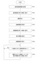
- FIG. 12 An example of the process executed by the control unit 9 of the information processing device 1 in this example is shown in Fig. 12. Note that the process shown in Fig. 12 shows a part of the process executed by each unit of the control unit 9, and the control unit 9 also executes a process for detecting an operation performed by a user and a process corresponding to the user operation. Moreover, the same processes as those shown in FIG. 8 and FIG. 10 are denoted by the same step numbers and descriptions thereof will be omitted as appropriate.
- step S151 the display image generating unit 11 of the control unit 9 acquires the reference distance information DIb and generates the reference image G4.
- the display control unit 12 of the control unit 9 displays the reference image G4 in the second area Ar2 in step S152.
- step S101 the control unit 9 issues a shooting instruction to the camera system 2.
- step S132 the control unit 9 requests the signal processing device 3 to obtain distance information.
- the signal processing device 3 generates a distance image G2 based on the imaging signal output from the distance measuring camera 4B.
- the display control unit 12 of the control unit 9 displays the distance image G2 in the first area Ar1 in step S133.
- step S153 the control unit 9 calculates difference information for each small area ArS in the distance image G2 and the reference image G4.
- step S154 the display control unit 12 of the control unit 9 superimposes the highlighted image Wi on the reference image G4 in the second area Ar2.
- step S137 the control unit 9 determines whether or not a selection operation has been performed on the small area ArS. If it is determined that a selection operation has been performed, the display control unit 12 of the control unit 9 causes the difference information for the selected small area ArS to be displayed in the third area Ar3 in step S138.
- step S138 After completing the process of step S138, or after determining in step S137 that a selection operation has not been performed on the small area ArS, the control unit 9 returns to the process of step S137.
- difference information for a small area ArS in which the difference between the reference image G4 and the distance image G2 is large in the area surrounded by the highlighted image Wi may be automatically displayed in the third area Ar3.
- difference information of a small area ArS inside the highlighted image Wi that has a large difference may be displayed in the third area Ar3.
- a switching button 302 may be arranged on the third screen 300.
- the highlighted image Wi may not be superimposed on the second area Ar2.
- the switch button 302 is an operator for switching the image displayed in the first area Ar1 between the distance image G2 and the reference image G4. For example, while the switch button 302 is pressed, the reference image G4 is displayed in the first area Ar1, and while the switch button 302 is not pressed, the distance image G2 is displayed in the first area Ar1.
- the user can compare the distance image G2 and the reference image G4, which are displayed in the same area in a time-division manner, and can easily check small areas ArS with large differences in the distance image G2 and the reference image G4 by using the afterimage. This also ensures ease of confirmation without the need for superimposed display of the highlighted image Wi.
- FIG. 14 shows an example of the process executed by the control unit 9 of the information processing device 1 to realize the display mode shown in FIG. 13. Note that the same process as in FIG. 12 is given the same step number and the description is omitted.
- the control unit 9 executes the processes of steps S151, S152, S101, S132, and S133 to display the reference image G4 in the second area Ar2 and the distance image G2 in the first area Ar1.
- step S171 the control unit 9 determines whether the switching button 302 is being pressed. If it is determined that the switching button 302 is being pressed, in step S172, the display control unit 12 of the control unit 9 causes the reference image G4 to be displayed in the first area Ar1.
- step S171 If it is determined in step S171 that the switching button 302 is not being pressed, or after the process of step S172 is completed, the control unit 9 appropriately executes the processes of steps S137 and S138, thereby causing difference information to be displayed in the third area Ar3 in response to a selection operation on the small area ArS.
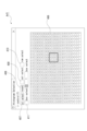
- a fourth screen 400 displayed on the display unit Ma has a first area Ar1, a second area Ar2, a fourth area Ar4, and a fifth area Ar5.
- a superimposed image G3 is displayed in the first area Ar1, and a distance image G2 is displayed in the second area Ar2.
- the fourth area Ar4 is an area where a histogram graph for each light receiving area ArR (or for each small area ArS in the distance image G2) is displayed.
- the histograms displayed in the fourth area Ar4 may be all 576 histograms from light receiving area ArR(0,0) to light receiving area ArR(23,23), or only a portion of these histograms may be displayed.
- the fourth area Ar4 displays a histogram display area 401, a histogram button 402 that displays histograms for all light receiving areas ArR, a reference button 403 that displays the zeroth order light, a selection display button 404 that displays only the selected histogram, and a peak button 405 that displays the peak value of the histogram.
- the zero-order light refers to the light emitted from the light-emitting unit 4Bb of the distance measurement camera 4B that is reflected by the lens group arranged in front of it and is received by the distance measurement sensor 4Ba.
- the zero-order light is a component that becomes noise in the distance measurement results.
- the fifth area Ar5 is an operation area for selecting the histogram to be displayed in the fourth area Ar4.
- the fifth region Ar5 is shown in an enlarged scale in FIG.
- the fifth area Ar5 is provided with an individual selection field 406 in which the light receiving area ArR can be individually selected.
- the individual selection field 406 can also be regarded as an area for individually selecting the small area ArS in the distance image G2 or an area for individually selecting the distance information DI(m, n).
- serial IDs (0 to 575) are arranged in 576 rectangular fields that mimic the layout of the light receiving area ArR. By selecting each serial ID, it is possible to select the histogram to be displayed in the fourth area Ar4.
- the fifth area Ar5 also includes a select all button 407 for selecting all light receiving areas ArR, and a reset button 408 for canceling the selection state in the individual selection field 406.
- the fifth area Ar5 includes a column selection button 409 for collectively selecting a vertical row including the light receiving area ArR selected in the individual selection field 406, and a row selection button 410 for collectively selecting a horizontal row including the light receiving area ArR selected in the individual selection field 406.
- the vertical column including that light receiving area ArR becomes selected, and a histogram for the selected light receiving area ArR is displayed in the histogram display area 401 of the fourth area Ar4.
- a box selection button 411 is arranged in the fifth area Ar5 for selecting multiple light receiving areas ArR in the shape of a rectangular box.
- the control unit 9 of the information processing device 1 in this example has an auxiliary function for selecting an arbitrary icon image PF from multiple icon images PF displayed densely on the superimposed image G3.
- FIG. 18 shows an example of an operation for selecting one of multiple icon images PF arranged on the superimposed image G3.
- FIG. 18 shows an enlarged view of a portion of the superimposed image G3, displaying multiple icon images PF and a cursor Cr that moves on the screen by the user's mouse operation, etc.
- a circular dashed line image Wi1 is superimposed around the icon image PF, indicating that the icon image PF closest to the cursor Cr is the target of the selection operation, as shown in the right diagram of FIG. 18.
- the speech bubble image Wi2 contains, for example, an x-coordinate and a y-coordinate (both x and y are integer values from 0 to 23) in a speech bubble-shaped enclosure, a serial ID for the light receiving area ArR, distance information DI, and reliability information indicating the accuracy of the distance.
- the icon image PF closest to the cursor Cr is selected, and the corresponding histogram is displayed in the histogram display area 401 of the fourth area Ar4.
- a selection operation e.g., a mouse click operation
- FIG. 19 shows an example of an operation for selecting multiple icon images PF from multiple icon images PF arranged on a superimposed image G3.
- the left diagram in FIG. 19 is the same as the left diagram in FIG. 18.
- a range image Wi3 is displayed, which indicates that the light receiving regions ArR included within a predetermined radius centered on the cursor Cr can be simultaneously selected.
- the icon image PF closest to the cursor Cr is selected, as in the previous example. Then, a histogram corresponding to the selected icon image PF is displayed in the histogram display area 401 of the fourth area Ar4.
- control unit 9 of the information processing device 1 in this example is capable of executing a process to highlight the light receiving area ArR from which the original data of the selected histogram was obtained.
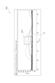
- FIG. 20 shows an example of an enlarged histogram displayed in the histogram display area 401 of the fourth area Ar4.
- a selected rectangular image Wi4 is displayed as a rectangle in Figure 20
- a histogram in which a portion of the graph is included in the selected rectangular image Wi4 is selected.
- the light receiving area ArR corresponding to the selected histogram is highlighted in the individual selection field 406 in the fifth area Ar5, as shown in FIG. 21.
- the corresponding icon image PF may be highlighted on the superimposed image G3 of the first area Ar1, or the corresponding small area ArS may be highlighted on the distance image G2 of the second area Ar2. Also, multiple such highlighting may be performed simultaneously.
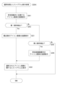
- FIG. 22 An example of the process executed by the control unit 9 of the information processing device 1 in this example is shown in Fig. 22. Note that the process shown in Fig. 22 shows a part of the process executed by each unit of the control unit 9, and the control unit 9 also executes a process for detecting an operation performed by a user and a process corresponding to the user operation. Note that the same steps as those described above will be given the same step numbers and the description will be omitted where appropriate.
- the control unit 9 of the information processing device 1 executes the processes of steps S101, S102, S103, S104, S105, and S106 shown in FIG. 8 to display the superimposed image G3 in the first area Ar1 of the fourth screen 400 and the distance image G2 in the second area Ar2.
- the control unit 9 acquires information for generating a histogram.
- the information for generating a histogram is individual unit distance information obtained from multiple image capture signals output from the distance measuring camera 4B, and is unit distance information obtained for each emission of the light-emitting element L.
- step S202 the display control unit 12 of the control unit 9 displays the histogram in the histogram display area 401 of the fourth area Ar4.
- step S203 the control unit 9 determines whether or not an icon image PF is present within a predetermined distance of the cursor Cr in the first area Ar1. In other words, in step S203, the control unit 9 determines whether or not an operation of bringing the cursor Cr closer to the icon image PF within a predetermined distance has been detected.
- the display control unit 12 of the control unit 9 performs a process in step S204 to indicate that the icon image PF to be selected has been selected, and to display only the histogram related to the selected icon image PF in the histogram display area 401 of the fourth area Ar4.
- step S204 After completing the process of step S204, or after determining in step S203 that no icon image PF exists within the predetermined distance of the cursor Cr, the control unit 9 determines in step S205 whether or not a histogram has been selected in the histogram display area 401.
- the display control unit 12 of the control unit 9 highlights the distance information DI corresponding to the selected histogram in step S206.
- highlighting may involve highlighting in the individual selection field 406 in the fifth area Ar5, highlighting the corresponding icon image PF on the superimposed image G3 in the first area Ar1, or highlighting the corresponding small area ArS on the distance image G2 in the second area Ar2.
- step S206 After completing step S206, or after determining in step S205 that a histogram selection operation has not been detected, the control unit 9 returns to the process of step S203.
- step S204 two examples of the process in step S204 will be described.
- the first processing example is shown in FIG.
- step S221 the display control unit 12 of the control unit 9 highlights the icon image PF closest to the cursor Cr.
- the display control unit 12 of the control unit 9 causes the histogram relating to the icon image PF selected in step S222 to be displayed in the histogram display area 401.
- the control unit 9 ends the series of processes shown in FIG. An example of this is shown in FIG.
- step S241 the display control unit 12 of the control unit 9 highlights the icon images PF located within a predetermined distance of the cursor Cr.
- the control unit 9 determines whether or not a first operation has been detected in step S242.
- the first operation here is, for example, the left click operation of the mouse as described above.
- the display control unit 12 of the control unit 9 highlights the nearest icon image PF in step S221, and displays the histogram of the selected object in the histogram display area 401 in step S222, completing the series of processes in FIG. 24.
- step S242 If it is determined in step S242 that the first operation has not been detected, the control unit 9 determines in step S243 whether or not the second operation has been detected.
- the second operation here is, for example, the right-click operation of the mouse as described above.
- the display control unit 12 of the control unit 9 highlights the icon image PF within a predetermined distance range of the cursor Cr in step S244. Furthermore, the display control unit 12 of the control unit 9 displays the histogram of the selected object in the histogram display area 401 in step S222.
- step S242 If it is determined in step S242 that the first operation has not been detected, and if it is determined in step S243 that the second operation has not been detected, the display control unit 12 ends the series of processes shown in Figure 24 without changing the display of the histogram. An example of this is shown in FIG.
- This example is an example in which distance information DI as time-series data acquired at different timings and distance information DI in spatially different light-receiving regions ArR are displayed as animation.
- the fifth screen 500 displayed on the display unit Ma is configured to include a first area Ar1, a second area Ar2, a fourth area Ar4, and a fifth area Ar5, similar to the fourth example. Moreover, since the configuration of each region is the same as in the fourth example, the same reference numerals as in the fourth example will be used for the explanation.
- the information processing device 1 holds time series data for the distance information DI. Therefore, data for the histogram of the distance information DI, which is acquired at different times, is stored as time series data in the information processing device 1. However, this is not limited to the above, and the histogram as time series data may be acquired each time from the signal processing device 3 or another information processing device.
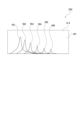
- the histogram display area 401 in the fourth area Ar4 displays histograms HG1, HG2, HG3, HG4, HG5, and HG6 in sequence over time, as shown in FIG. 25. That is, in the histogram display area 401, an animation display is provided using histograms HG1, HG2, HG3, HG4, HG5, and HG6.
- Such animation display may also be performed when an operation is performed to select one small area ArS in the second area Ar2, or when an operation is performed to select one light receiving area ArR displayed in the individual selection field 406 in the fifth area Ar5.
- histograms HG1, HG2, HG3, HG4, HG5, HG6... for the icon images PF located in the vicinity of the trajectory LC of the cursor Cr may be displayed in an animated manner in the histogram display area 401 in the fourth area Ar4, as shown in FIG.
- the display order of the histograms HG1, HG2, HG3, HG4, HG5, and HG6 is the order in which the cursor Cr passes near the corresponding icon images PF.
- animation displays are also possible.
- a parameter that affects the histogram waveform such as the emission intensity of the light-emitting element L provided in the light-emitting unit 4Bb of the distance measuring camera 4B
- histograms HG7, HG8, HG9, and HG10 obtained in sequence in accordance with the change in emission intensity may be displayed in sequence in the histogram display area 401 in the fourth area Ar4, as shown in FIG. 27.
- the display color of the icon image PF in the superimposed image G3 displayed in the first area Ar1 and the display color of the small area ArS in the distance image G2 displayed in the second area Ar2 may also be animated to correspond to the change in distance. That is, each time the histogram display changes, the display colors may also change accordingly.
- a function for assisting the selection operation regarding such distance information DI will be described.
- an auxiliary function for selecting an icon image PF in which the distance information DI changes greatly in the first area Ar1 will be described.
- the icon image PF with the greatest change in distance information DI between the start and end of the animation is automatically selected from among the multiple icon images PF contained within the selected selection area ArSel (see FIG. 29).
- a histogram for the automatically selected icon image PF may be displayed (or may be displayed as an animation). Also, in the second area Ar2, the small area ArS corresponding to the automatically selected icon image PF may be highlighted.
- This type of auxiliary function can also be applied when the user selects a small area ArS in the second area Ar2 that exhibits a large change in display color during animation.
- FIG. 30 An example of the process executed by the control unit 9 of the information processing device 1 in this example is shown in Fig. 30. Note that the process shown in Fig. 30 shows a part of the process executed by each unit of the control unit 9, and the control unit 9 also executes a process for detecting an operation performed by a user and a process corresponding to the user operation. Note that the same steps as those described above will be given the same step numbers and the description will be omitted as appropriate.
- the control unit 9 of the information processing device 1 executes the processes of steps S101, S102, S103, S104, S105, and S106 shown in FIG. 8 to display a superimposed image G3 in the first area Ar1 of the fifth screen 500 and a distance image G2 in the second area Ar2.
- the control unit 9 determines whether or not one light receiving area ArR was selected in step S261. Specifically, the control unit 9 detects an operation to select one of the icon images PF displayed in the first area Ar1, an operation to select one of the small areas ArS in the second area Ar2, or an operation to select one of the light receiving areas ArR displayed in the individual selection field 406 in the fifth area Ar5.
- the display control unit 12 of the control unit 9 displays an animation of the time series data of the histogram for the selected light receiving area ArR in step S262 (see, for example, FIG. 25).
- step S263 determines in step S263 whether an operation of drawing a predetermined trajectory LC (e.g., see FIG. 26) on the first area Ar1 has been detected.
- the display control unit 12 of the control unit 9 displays an animation of a histogram based on the trajectory LC in step S264.
- step S264 or after determining in step S263 that an operation to draw a trajectory LC has not been detected, the control unit 9 determines in step S265 whether an operation to display an animation based on a parameter change has been detected.
- the display control unit 12 of the control unit 9 displays an animation of the time series data of the histogram based on the parameter change in step S266.
- step S266 or after determining in step S265 that an operation for displaying an animation has not been detected, the control unit 9 ends the series of processes shown in FIG. 30.
- steps S262, S264, and S266 are shown in FIG. 31.
- the display control unit 12 of the control unit 9 starts displaying an animation corresponding to the operation mode in step S281.
- the animation display started here can be executed in different modes in steps S262, S264, and S266.
- control unit 9 determines in step S282 whether or not a selection area ArSel as shown in FIG. 28 has been set.
- the display control unit 12 of the control unit 9 highlights the distance information DI that has a large change within the selection area ArSel in step S283 (see FIG. 29, for example).
- the display modes of the first, second and third examples of the screen displayed on the display unit Ma may be switchable between each other.
- the arrangement of the first area Ar1, the second area Ar2, the third area Ar3, the fourth area Ar4, and the fifth area Ar5 may be freely set by the user.
- a menu for realizing the display mode in the first example and a menu for realizing the display mode in the second example may be provided, and the display may be switched by appropriately selecting one of these menus.
- the information processing device 1 is equipped with a display control unit 12 that displays a superimposed image G3 in a first area Ar1 on the display unit Ma, in which distance information DI to the subject is superimposed on a luminance image G1 generated based on luminance information about reflected light from the subject, and the superimposed position of the distance information DI on the luminance image G1 is the position on the luminance image G1 for the subject from which the distance information DI was obtained.
- the luminance image G1 is, for example, a color image such as an RGB image, a monochrome image, etc.
- the distance information DI may be superimposed by superimposing characters or an image.
- the display control unit 12 in the information processing device 1 may cause the distance image G2 generated based on the distance information DI to be displayed in the second area Ar2. This makes it possible to display the superimposed image G3 and the distance image G2 side by side, etc. Therefore, by comparing these images, it is possible to improve work efficiency.
- the display control unit 12 in the information processing device 1 may display in the third area Ar3 the distance information DI for an image that is the target of a selection operation from the distance information DI superimposed on the superimposed image G3. This makes it possible to display detailed information of the distance information DI in the third area Ar3, and also makes it easy to know which distance information DI on the superimposed image G3 corresponds to the detailed information, thereby further improving work efficiency.
- the display control unit 12 in the information processing device 1 superimposes the distance information DI onto the luminance image G1 using an icon image PF that reflects the distance information DI, and the display color of the icon image PF may correspond to the distance of the distance information DI.
- the display color of the icon image PF may correspond to the distance of the distance information DI.
- the display control unit 12 in the information processing device 1 may change the correspondence between the distance and the display color in response to an operation and cause the display to be displayed. This allows the color change relative to the change in distance to be non-linear in a certain distance range, making it possible to inspect the distance information DI in more detail and improving the efficiency of debugging the distance measuring sensor 4Ba.
- the display control unit 12 in the information processing device 1 may display a distance image G2 based on distance information DI obtained about the subject in either the first area Ar1 or the second area Ar2, and display a difference image G5 generated based on the difference between a reference image G4 that serves as the basis for the distance image G2 and the distance information (distance information DI and reference distance information DIb) of the distance image G2 in the other area.
- the reference image G4 is a distance image generated based on accurate distance information DI and is an image that should be obtained as the distance image G2.
- the display control unit 12 in the information processing device 1 may switch from displaying the differential image G5 to displaying the distance image G2 in response to a switching operation.
- This makes it possible to switch between a display mode suitable for comparing the distance image G2 with the reference image G4 and a display mode suitable for comparing the distance image G2 with the difference image G5 depending on the situation. Therefore, it becomes possible to efficiently perform debugging of the distance measuring sensor 4Ba from a variety of perspectives.
- the display control unit 12 in the information processing device 1 may display an operator (switching button 201) for switching operations. This makes it possible to easily switch between a plurality of display modes by, for example, a click operation.
- the display control unit 12 in the information processing device 1 may display in the third area Ar3 distance difference information corresponding to the area that was the target of the selection operation on the difference image G5.
- This allows the difference between the distance information (distance information DI and reference distance information DIb) in the selected area of distance image G2 and reference image G4 to be confirmed in detail in the third area Ar3. That is, the efficiency of the work can be improved by using more information.
- the display control unit 12 in the information processing device 1 may superimpose and display an emphasis image Wi for at least one of the distance image G2 and the reference image G4 to emphasize areas where the difference in distance information (distance information DI and reference distance information DIb) in the distance image G2 and the reference image G4 is greater than or equal to a predetermined value.
- the highlighted image Wi is, for example, a circular image surrounding the relevant area.
- the display control unit 12 in the information processing device 1 may display distance information DI for the area on which the highlighted image Wi is superimposed in the third area Ar3 in response to a selection operation on the highlighted image Wi. That is, by performing a click operation or the like on the highlighted image Wi, difference information about that area can be presented in the third area Ar3. Therefore, the user can easily check the difference information. Furthermore, when multiple highlighted images Wi are superimposed on multiple regions, the user can easily switch the information displayed in the third region Ar3 by performing a click operation to switch the selection of the multiple highlighted images Wi.
- the display control unit 12 in the information processing device 1 may display an operator (switch button 302) for a switching operation to switch the display, and switch the image to be displayed in the area where the reference image G4 is displayed between the reference image G4 and the distance image G2 in accordance with the operation of the operator (switch button 302).
- switch button 302 the image displayed in the second area Ar2 to be switched between the reference image G4 and the distance image G2. That is, the image displayed in the same area is switched with each switching operation, so that the difference between the reference image G4 and the distance image G2 can be easily grasped.
- the display control unit 12 in the information processing device 1 may display the cursor Cr at a position on the display unit Ma in response to the user's operation, and highlight on the superimposed image G3 the distance information DI superimposed on the luminance image G1 that is in the vicinity of the display position of the cursor Cr. This allows the user to easily select any piece of distance information DI even when the pieces of distance information DI are densely superimposed.
- the display control unit 12 in the information processing device 1 may display a histogram of the distance information DI superimposed on the luminance image G1 in the fourth area Ar4. Specifically, a plurality of pieces of unit distance information are obtained by performing light reception at the light receiving pixels of the distance measuring sensor 4Ba and calculating the unit distance information a plurality of times. Then, in the histogram, the plurality of pieces of unit distance information are represented as frequency information. This makes it possible to visually check variations in distance measurement information, which contributes to improving the efficiency of debugging work.
- the display control unit 12 in the information processing device 1 may display histograms for each of the multiple distance information DI superimposed on the luminance image G1 in the fourth area Ar4, and highlight the distance information DI corresponding to a portion of the histograms selected in the fourth area Ar4. This makes it possible to specify the approximate pixel position where the distance information DI is obtained when a distinctive histogram is mixed in with a plurality of histograms.
- the display control unit 12 in the information processing device 1 may highlight distance information DI with large changes in distance among the distance information DI located within a selection area ArSel selected by a selection operation that selects a portion of the area on the superimposed image G3. For example, when a histogram of a plurality of pieces of distance information DI is reproduced and displayed in chronological order, the distance information DI that changes significantly over time within the selected area ArSel is highlighted. Alternatively, when a selection area ArSel is set on the superimposed image G3, distance information DI that has a large difference from the reference image G4 may be highlighted. This allows the user to simply roughly set the selected area ArSel and automatically highlight the distance information DI that the user wishes to check in detail, thereby further improving work efficiency.
- the distance information DI is obtained by a ToF method using a light-emitting unit 4Bb and a light-receiving unit (ranging sensor 4Ba), and the superimposition position of the distance information DI on the luminance image G1 may be a position obtained by performing a process to convert the light-receiving position (light-receiving area ArR) of reflected light from a subject in the light-receiving unit (ranging sensor 4Ba) into a position on the luminance image G1.
- This allows a more accurate correspondence between a position on the distance image G2 corresponding to the distance information DI and a position on the luminance image G1. Therefore, the distance information DI can be accurately superimposed on the luminance image G1 of the subject, which facilitates debugging work and improves efficiency.
- the information processing method executed by the information processing device 1 includes a process of displaying a superimposed image G3 in a first area Ar1 on the display unit Ma, in which distance information DI to the subject is superimposed on a luminance image G1 generated based on luminance information about reflected light from the subject, and the superimposed position of the distance information DI on the luminance image G1 is set to the position on the luminance image G1 for the subject from which the distance information DI was obtained.
- the program in this technology is a program executed by a calculation processing device, and includes a process for displaying a superimposed image G3 in a first area Ar1 on a display unit Ma, in which distance information DI to the subject is superimposed on a luminance image G1 generated based on luminance information about reflected light from the subject, and the superimposed position of the distance information DI on the luminance image G1 is set to the position on the luminance image G1 for the subject from which the distance information DI was obtained.
- These programs can be pre-recorded in a HDD (Hard Disk Drive) as a recording medium built into a device such as a computer device, or in a ROM in a microcomputer having a CPU.
- the programs can be temporarily or permanently stored (recorded) in a removable recording medium such as a flexible disk, a CD-ROM (Compact Disk Read Only Memory), an MO (Magneto Optical) disk, a DVD (Digital Versatile Disc), a Blu-ray Disc (registered trademark), a magnetic disk, a semiconductor memory, or a memory card.
- a removable recording medium can be provided as so-called package software.
- such a program can be installed in a personal computer or the like from a removable recording medium, or can be downloaded from a download site via a network such as a LAN (Local Area Network) or the Internet.
- LAN Local Area Network
- the present technology can also be configured as follows. (1) a display control unit that displays a superimposed image in a first area on a display unit, the superimposed image being generated based on luminance information regarding reflected light from a subject and having information regarding a distance to the subject superimposed thereon; The superimposition position of the distance information on the luminance image is set to a position on the luminance image for the subject from which the distance information was obtained. (2) The information processing device according to (1), wherein the display control unit causes a distance image generated based on the distance information to be displayed in a second area.
- the information processing device displays, in a third area, distance difference information corresponding to an area that is a target of a selection operation on the difference image.
- the display control unit displays an emphasis image for superimposing on at least one of the distance image and the reference image an emphasis image for emphasizing an area where the difference in distance information between the distance image and the reference image is greater than or equal to a predetermined value.
- the display control unit causes the distance information for a region on which the emphasis image is superimposed to be displayed in a third region in response to a selection operation on the emphasis image.
- the display control unit is Display the controls for switching between displays, The information processing device according to any one of (10) to (11) above, wherein an image to be displayed in an area in which the reference image is displayed is switched between the reference image and the distance image in response to an operation of the operator. (13) The display control unit is displaying a cursor on the display unit at a position corresponding to a user's operation; The information processing device according to any one of (1) to (12) above, wherein the distance information superimposed on the luminance image, the distance information in the vicinity of a display position of the cursor, is highlighted on the superimposed image.
- the information processing device causes a histogram of the distance information superimposed on the luminance image to be displayed in a fourth area.
- the display control unit is displaying, in the fourth area, histograms of each of the plurality of pieces of distance information superimposed on the luminance image;
- the information processing device according to (14) above, wherein the distance information corresponding to a part of the histogram selected in the fourth area is highlighted.
- the display control unit is The information processing device described in any one of (1) to (15) above, which highlights the distance information located within a selection area selected by a selection operation that selects a portion of the area on the superimposed image, the distance information having a large change in distance.
- the distance information is obtained by a ToF method using a light emitting unit and a light receiving unit, The information processing device described in any of (1) to (16) above, wherein the superimposition position of the distance information on the luminance image is a position obtained by performing a process of converting the receiving position of reflected light from the subject at the light receiving unit into a position on the luminance image.
- An information processing method performed by an information processing device a process for displaying a superimposed image in a first area on a display unit, the superimposed image being generated based on luminance information regarding reflected light from a subject and having information regarding a distance to the subject superimposed thereon; a superimposition position of the distance information on the luminance image is determined to be a position on the luminance image for the subject from which the distance information was obtained.
- Information processing device 12 Display control unit 201 Switching button (operator) 302 Switch button (operator) Ar1 First area Ar2 Second area Ar3 Third area Ar4 Fourth area ArSel Selection area Cr Cursor DI Distance information G1 Luminance image G2 Distance image G3 Superimposed image G4 Reference image G5 Difference image Ma Display unit PF Icon image Wi Highlighted image
Landscapes
- Engineering & Computer Science (AREA)
- Physics & Mathematics (AREA)
- General Physics & Mathematics (AREA)
- Theoretical Computer Science (AREA)
- Computer Hardware Design (AREA)
- Radar, Positioning & Navigation (AREA)
- Remote Sensing (AREA)
- Computer Networks & Wireless Communication (AREA)
- General Engineering & Computer Science (AREA)
- Electromagnetism (AREA)
- Human Computer Interaction (AREA)
- Length Measuring Devices By Optical Means (AREA)
Abstract
Description
例えば、下記特許文献1においては、距離情報に基づいて二次元の濃淡画像を生成する際に、高さ情報の欠落を抑制して精度の低下を抑える技術が開示されている。
輝度画像とは、例えば、RGB画像などのカラー画像やモノクロ画像などである。また、距離情報の重畳は、文字を重畳させることによって行ってもよいし、画像を重畳させることによって行ってもよい。
これにより、輝度画像と距離情報の対応を一目で把握することが容易になる。
<1.情報処理システムの構成>
<2.重畳画像>
<3.各種画面>
<3-1.第1例>
<3-2.第2例>
<3-3.第3例>
<3-4.第4例>
<3-5.第5例>
<4.その他>
<5.まとめ>
<6.本技術>
本技術の実施の形態に係る情報処理装置1を含む情報処理システムSの構成例を図1に示す。
即ち、発光部4Bbは、左上に配置された発光素子L(0、0)から右下に配置された発光素子L(23、23)までの合計576個の発光素子Lを有して構成されている。
各SPAD素子は、発光素子Lに対応して赤外光のみに感度を有する。従って、SPAD素子は、発光素子Lから照射され被写体で反射した赤外光を主に受光する。
図示するように、受光領域ArRは、発光素子Lの数だけ設けられ得る。但し、赤外光が測距センサ4Baの範囲外を通る場合には、受光領域ArRは発光素子Lよりも少なくなる。
また、測距カメラ4Bからは後段の信号処理装置3に対して距離画像を生成するための撮像信号が出力される。
制御部9は、信号処理装置3に対して種々のコマンドを送信することにより信号処理装置3における各画像の生成を実現させる。また、制御部9は、信号処理装置3を介してカメラシステム2を制御する。
表示画像生成部11は、表示装置Mの表示部Maに表示させる画像を生成する機能を有する。表示画像生成部11が生成する画像には、輝度画像G1に距離情報DIを重畳させた重畳画像G3が含まれる。重畳画像G3については改めて後述する。
即ち、情報処理システムSは、測距センサ4Baによって生成される距離情報DIの精度をユーザが確認するために用いるシステムである。
重畳画像G3について説明する。重畳画像G3は、輝度画像生成部7によって生成された輝度画像G1に距離情報DIを重畳させたものである。
図示するように、重畳画像G3は、輝度画像G1に対して、測距センサ4Baの各受光領域ArRでの受光結果に応じて算出された距離情報DIが重畳されたものとなる。
他にも、アイコン画像PFの透明度の高さで距離情報DIを表現するなど、種々の態様が考えられる。
ここで、表示画像生成部11は、輝度画像G1上における距離情報DIの重畳位置を算出するための処理を実行することで、輝度画像G1の適切な位置に距離情報DIが重畳された重畳画像G3を生成する。
なお、以下の説明においては、補正処理を行う前の距離情報を処理前距離情報DIaと記載する。
表示画像生成部11は、補正前の距離情報である処理前距離情報DIaに対して、先ず、受光領域ArRの位置及び大きさに基づく補正処理を行う(ステップS1)。この補正処理では、処理対象の受光領域ArRに対応した発光素子Lの発光ごとに得られる個々の距離情報(ここでは単位距離情報とする)に基づいてヒストグラムが生成される。
また、オフセット補正処理では、個々の単位距離情報から生成されたヒストグラムのピーク値を当該受光領域ArRについての代表距離情報として決定する。
換言すれば、ステップS5の処理は、RGBセンサ4Aa上において測距センサ4Baの受光領域ArRの対応点を求め、更に、上述した距離ZからRGBセンサ4Aaを含む面と被写体を含む面の面同士の距離へと変換する処理である。
表示装置Mの表示部Maに表示される画面と表示制御について添付図を参照して幾つかの例を説明する。
表示部Maに表示される画面の第1例を図6に示す。
各領域は、互いに重ならないように配置されてもよいし、ウィンドウの拡大及び縮小がなされることによりそれぞれの一部の領域が重なるように配置可能とされてもよい。
距離画像G2は、矩形状の小領域ArSが行列状に配置されて成る。それぞれの小領域ArSは、受光領域ArRそれぞれに対応しており、表示色が受光領域ArRについての距離情報DIに基づく色とされている。例えば、受光領域ArRの表示色と対応するアイコン画像PFの表示色は同色とされている。
ユーザによる選択操作によって重畳画像G3に重畳された一つのアイコン画像PFや距離画像G2における小領域ArSが選択された場合に、選択対象のアイコン画像PFや小領域ArSに紐付く距離情報DIに関する種々の情報が第3領域Ar3に表示される。
また、コントロールボタン103を押下した後の第2領域Ar2には、コントロールボタン103を押下する前から表示されている凡例101と距離画像G2が表示されている。
例えば、下限入力欄105に「3000」を入力し上限入力欄106に「3500」を入力すると、3mから3.5mに位置する被写体についての距離情報DIの差分が見やすいような表示態様(ノンリニア表示)へと変更することができる。
即ち、ユーザは、距離情報DIと表示色の対応関係を変更することができる。
即ち、自動ボタン108は、距離画像G2に含まれる最小の距離情報DIと最大の距離情報DIの間で表示色がリニアに変化するような表示態様に変更する操作子とされる。
また、これに応じて第1領域Ar1に表示された重畳画像G3において重畳されたアイコン画像PFの表示色も同様に変更される。
表示部Maに表示される画面の第2例を図9に示す。
第2例において表示部Maに表示される第2画面200は、第1領域Ar1と第2領域Ar2と第3領域Ar3から成る。また、第2画面200には、切替ボタン201が配置されている。
基準画像G4は、正確な距離情報DIによって生成される距離画像である。正確な距離情報DIとは、カメラシステム2の測距カメラ4Bによる撮像と上述した処理前距離情報DIaの補正処理によって得られるべきRGBカメラ4Aと被写体についての距離情報DIである。
差分画像G5は、距離画像G2における受光領域ArRごとの距離情報DIと、基準画像G4における受光領域ArRごとの基準距離情報DIbの差分に基づいて生成される画像である。距離画像G2と基準画像G4と差分画像G5は、同じ数の小領域ArSから成る。
座標情報は、本例では、0から23までの整数値で表される。
また、第3領域Ar3には全てのレコードを削除する全クリアボタン202が設けられている。
また、図8に示す処理と同様の処理については同じステップ番号を付し適宜説明を省略する。
表示部Maに表示される画面の第3例を図11に示す。
第3例において表示部Maに表示される第3画面300は、第1領域Ar1と第2領域Ar2と第3領域Ar3から成る。
なお、第1領域Ar1及び第2領域Ar2に凡例を表示させてもよい。
なお、第3領域Ar3には、全てのレコードを削除する全クリアボタン301が設けられている。
また、図8及び図10に示す処理と同様の処理については同じステップ番号を付し適宜説明を省略する。
或いは、強調画像Wiに対するクリック操作を検出した場合に、その内側の領域で差分が大きい小領域ArSの差分情報が第3領域Ar3に表示されるようにしてもよい。
また、これにより、強調画像Wiを重畳表示しなくても確認の容易性を担保することができる。
表示部Maに表示される画面の第4例を図15に示す。
第4例において表示部Maに表示される第4画面400は、第1領域Ar1と第2領域Ar2と第4領域Ar4と第5領域Ar5を有している。
第5領域Ar5には、受光領域ArRを個別に選択可能な個別選択欄406が設けられている。なお、個別選択欄406は、距離画像G2における小領域ArSを個別に選択する領域、或いは、距離情報DI(m、n)を個別に選択する領域と捉えることもできる。
例えば、ユーザがカーソルCrを動かすためのマウスを用いてドラッグ操作を行うと、図20の矩形の四角とされた選択矩形画像Wi4が表示されると共に、選択矩形画像Wi4にグラフの一部が含まれるヒストグラムが選択状態とされる。
なお、これまでに説明した処理と同様の処理については同じステップ番号を付し適宜説明を省略する。
一つ目の処理例について図23に示す。
制御部9の表示制御部12は、ステップS221でカーソルCrの最近傍のアイコン画像PFを強調表示させる。
この例は、図18に示したものである。
制御部9の表示制御部12はステップS241で、カーソルCrの所定距離内に位置するアイコン画像PFを強調表示させる。
この例は、図19に示したものである。
本例では、取得タイミングが異なる時系列データとしての距離情報DIや空間上異なる受光領域ArRでの距離情報DIをアニメーション表示する例である。
第5例において表示部Maに表示される第5画面500は、第4例と同様に、第1領域Ar1と第2領域Ar2と第4領域Ar4と第5領域Ar5を備えて構成されている。
また、各領域の構成については第4例と同様であるため、第4例と同じ符号を用いて説明する。
このとき、ヒストグラムHG1、HG2、HG3、HG4、HG5、HG6の表示順は、対応するアイコン画像PFの近傍をカーソルCrが通過した順とされる。
一例として、第1領域Ar1において距離情報DIの変化の大きいアイコン画像PFを選択するための補助機能を説明する。
なお、これまでに説明した処理と同様の処理については同じステップ番号を付し適宜説明を省略する。
表示部Maに表示される画面について上述した第1例と第2例と第3例の表示態様は、互いに表示の切り替えが可能にされていてもよい。
例えば、第1領域Ar1と第2領域Ar2と第3領域Ar3と第4領域Ar4と第5領域Ar5の配置をユーザが自由に設定可能に構成されていてもよい。
或いは、第1例における表示態様を実現するためのメニューや、第2例における表示態様を実現するためのメニューなどがそれぞれ設けられ、それらのメニューを適宜選択することにより表示の切り換えが行われてもよい。
上述した各例で説明したように、情報処理装置1は、被写体における反射光についての輝度情報に基づいて生成された輝度画像G1に被写体までの距離情報DIを重畳させた重畳画像G3を表示部Ma上の第1領域Ar1に表示させる表示制御部12を備え、輝度画像G1上における距離情報DIの重畳位置は、距離情報DIが得られた被写体についての輝度画像G1上における位置とされている。
輝度画像G1とは、例えば、RGB画像などのカラー画像やモノクロ画像などである。また、距離情報DIの重畳は、文字を重畳させることによって行ってもよいし、画像を重畳させることによって行ってもよい。
表示制御部12によるこのような制御によって表示装置Mの表示部Maにおける表示がなされることにより、輝度画像G1と距離情報DIの対応を一目で把握することが容易になる。従って、輝度画像G1と距離情報DIを交互に表示させることにより測距センサ4Baの開発時のデバッグ作業や製造検査などを行うよりも作業効率の向上を図ることができる。
これにより、重畳画像G3と距離画像G2を並べて表示することなどが可能となる。従って、それらの画像を見比べることで作業効率の向上を図ることができる。
これにより、距離情報DIの詳細情報を第3領域Ar3に表示させることなどが可能となる。また、詳細な情報が重畳画像G3上における何れの距離情報DIであるかを容易に把握することができる。これにより、作業効率の向上をより一層図ることができる。
表示色と距離を関連付けることで、一目見ただけで被写体についての輝度画像G1と距離情報DIの関係を把握することができる。
従って、作業効率の向上を図ることができる。
これにより、一部の距離範囲において、距離の変化に対する色の変化をノンリニアにすることができる。従って、より詳細に距離情報DIを検査することが可能となり、測距センサ4Baのデバッグ作業の効率を向上させることができる。
基準画像G4とは、正確な距離情報DIによって生成される距離画像であり距離画像G2として得られるべき画像である。上述した構成を備えることにより、基準画像G4と撮像により得られた距離画像G2の比較結果を容易に把握することができ、作業効率の向上を図ることができる。
これにより、距離画像G2と基準画像G4の比較を行う場合に好適な表示態様と、距離画像G2と差分画像G5の比較に好適な表示態様とを、状況に応じて切り替えることが可能となる。
従って、多種多様な観点から測距センサ4Baのデバッグ作業を効率よく行うことが可能となる。
これにより、例えばクリック操作などで複数の表示態様を容易に切り替えることが可能となる。
これにより、距離画像G2と基準画像G4について選択された領域における距離情報(距離情報DIと基準距離情報DIb)の差分を第3領域Ar3で詳細に確認することができる。
即ち、より多くの情報を用いて作業効率の向上を図ることができる。
これにより、差分のある領域を一目で把握することが可能となり、作業効率の向上が図られる。強調画像Wiとは、例えば、該当領域を囲むような円形状の画像などである。
即ち、強調画像Wiに対するクリック操作等を行うことにより、第3領域Ar3に、当該領域についての差分情報を提示することができる。
従って、ユーザは差分情報を容易に確認することができる。また、複数の強調画像Wiが複数の領域に重畳されている場合には、複数の強調画像Wiの選択を切り替えるクリック操作を行うことにより、第3領域Ar3に表示される情報を容易に切り替えることができる。
これにより、例えば第2領域Ar2において表示される画像を基準画像G4と距離画像G2とで切り替えることができる。即ち、同じ領域に表示される画像が切替操作ごとに切り替わることにより、基準画像G4と距離画像G2の差分を容易に把握することができる。
これにより、距離情報DIが密集して重畳されている場合であっても、ユーザは任意の距離情報DIを容易に選択することができる。
具体的には、測距センサ4Baの受光画素における受光と単位距離情報の算出を複数回行うことにより、複数の単位距離情報を得る。そして、ヒストグラムにおいては、当該複数の単位距離情報が頻度情報として表現される。
これにより、測距情報のばらつきなどを目視で確認することができるため、デバッグ作業の効率向上に寄与する。
これにより、複数のヒストグラムの中に特徴のあるヒストグラムが混じっていた場合に、そのような距離情報DIが得られたおおよその画素位置を特定することができる。
例えば、複数の距離情報DIのヒストグラムを時系列順に表示させるように再生表示を行った場合に、選択領域ArSel内において時間変化の大きい距離情報DIが強調表示される。
或いは、重畳画像G3上で選択領域ArSelを設定した場合に、基準画像G4との差分が大きい距離情報DIが強調表示されるようにしてもよい。
これにより、大まかに選択領域ArSelを設定するだけで詳細を確認したい距離情報DIが自動的に強調され、作業効率の向上をより一層図ることができる。
これにより、距離情報DIに対応した距離画像G2上の位置と輝度画像G1上の位置がより正確に対応付けられる。
従って、被写体についての輝度画像G1上に距離情報DIを正確に重畳させることができるため、デバッグ作業をしやすくし、効率の向上を図ることができる。
また、このようなプログラムは、リムーバブル記録媒体からパーソナルコンピュータ等にインストールする他、ダウンロードサイトから、LAN(Local Area Network)、インターネットなどのネットワークを介してダウンロードすることもできる。
本技術は以下のような構成を採ることも可能である。
(1)
被写体における反射光についての輝度情報に基づいて生成された輝度画像に前記被写体までの距離情報を重畳させた重畳画像を表示部上の第1領域に表示させる表示制御部を備え、
前記輝度画像上における前記距離情報の重畳位置は、前記距離情報が得られた前記被写体についての前記輝度画像上における位置とされた
情報処理装置。
(2)
前記表示制御部は、前記距離情報に基づいて生成された距離画像を第2領域に表示させる
上記(1)に記載の情報処理装置。
(3)
前記表示制御部は、前記重畳画像に重畳された前記距離情報のうち選択操作の対象とされた画像についての前記距離情報を第3領域に表示させる
上記(1)から上記(2)の何れかに記載の情報処理装置。
(4)
前記表示制御部は、前記距離情報を反映させたアイコン画像を用いて前記輝度画像への前記距離情報の重畳を行い、
前記アイコン画像の表示色は前記距離情報の距離に応じたものとされた
上記(1)から上記(3)の何れかに記載の情報処理装置。
(5)
前記表示制御部は、操作に応じて距離と表示色の対応関係を変更して表示させる
上記(4)に記載の情報処理装置。
(6)
前記表示制御部は、第1領域と前記第2領域の何れか一方に前記被写体について得られた前記距離情報に基づく前記距離画像を表示させ、他方に前記距離画像の基準となる基準画像と前記距離画像の距離情報の差分に基づいて生成される差分画像を表示させる
上記(2)に記載の情報処理装置。
(7)
前記表示制御部は、切替操作に応じて前記差分画像から前記距離画像へ切り替えて表示させる
上記(6)に記載の情報処理装置。
(8)
前記表示制御部は、前記切替操作のための操作子を表示させる
上記(7)に記載の情報処理装置。
(9)
前記表示制御部は、前記差分画像上において選択操作の対象とされた領域に対応した距離の差分情報を第3領域に表示させる
上記(6)から上記(8)の何れかに記載の情報処理装置。
(10)
前記表示制御部は、前記距離画像及び前記基準画像の少なくとも一方について、前記距離画像と前記基準画像における距離情報の差分が所定以上とされた領域を強調するための強調画像を重畳させて表示させる
上記(6)に記載の情報処理装置。
(11)
前記表示制御部は、前記強調画像に対する選択操作に応じて前記強調画像が重畳された領域についての前記距離情報を第3領域に表示させる
上記(10)に記載の情報処理装置。
(12)
前記表示制御部は、
表示を切り替える切替操作のための操作子を表示させ、
前記操作子の操作に応じて前記基準画像が表示される領域に表示させる画像を前記基準画像と前記距離画像とで切り替える
上記(10)から上記(11)の何れかに記載の情報処理装置。
(13)
前記表示制御部は、
前記表示部上におけるユーザの操作に応じた位置にカーソルを表示させ、
前記輝度画像に重畳された前記距離情報のうち、前記カーソルの表示位置の近傍の前記距離情報を前記重畳画像上で強調表示させる
上記(1)から上記(12)の何れかに記載の情報処理装置。
(14)
前記表示制御部は、前記輝度画像に重畳された前記距離情報についてのヒストグラムを第4領域に表示させる
上記(1)から上記(13)の何れかに記載の情報処理装置。
(15)
前記表示制御部は、
前記輝度画像に重畳された複数の前記距離情報についてのそれぞれのヒストグラムを前記第4領域に表示させ、
前記第4領域において選択された一部のヒストグラムに対応した前記距離情報を強調表示させる
上記(14)に記載の情報処理装置。
(16)
前記表示制御部は、
前記重畳画像上の一部の領域を選択する選択操作によって選択された選択領域内に位置する前記距離情報のうち、距離の変化が大きい前記距離情報を強調表示させる
上記(1)から上記(15)の何れかに記載の情報処理装置。
(17)
前記距離情報は、発光部と受光部を用いたToF方式によって得られたものとされ、
前記輝度画像上における前記距離情報の重畳位置は、前記受光部における前記被写体からの反射光の受光位置を前記輝度画像上の位置に変換する処理を行うことにより得られた位置とされた
上記(1)から上記(16)の何れかに記載の情報処理装置。
(18)
演算処理装置に実行させるプログラムであって、
被写体における反射光についての輝度情報に基づいて生成された輝度画像に前記被写体までの距離情報を重畳させた重畳画像を表示部上の第1領域に表示させる処理を備え、
前記輝度画像上における前記距離情報の重畳位置は、前記距離情報が得られた前記被写体についての前記輝度画像上における位置とされた
プログラム。
(19)
情報処理装置が行う情報処理方法であって、
被写体における反射光についての輝度情報に基づいて生成された輝度画像に前記被写体までの距離情報を重畳させた重畳画像を表示部上の第1領域に表示させる処理を備え、
前記輝度画像上における前記距離情報の重畳位置は、前記距離情報が得られた前記被写体についての前記輝度画像上における位置とされた
情報処理方法。
12 表示制御部
201 切替ボタン(操作子)
302 切替ボタン(操作子)
Ar1 第1領域
Ar2 第2領域
Ar3 第3領域
Ar4 第4領域
ArSel 選択領域
Cr カーソル
DI 距離情報
G1 輝度画像
G2 距離画像
G3 重畳画像
G4 基準画像
G5 差分画像
Ma 表示部
PF アイコン画像
Wi 強調画像
Claims (19)
- 被写体における反射光についての輝度情報に基づいて生成された輝度画像に前記被写体までの距離情報を重畳させた重畳画像を表示部上の第1領域に表示させる表示制御部を備え、
前記輝度画像上における前記距離情報の重畳位置は、前記距離情報が得られた前記被写体についての前記輝度画像上における位置とされた
情報処理装置。 - 前記表示制御部は、前記距離情報に基づいて生成された距離画像を第2領域に表示させる
請求項1に記載の情報処理装置。 - 前記表示制御部は、前記重畳画像に重畳された前記距離情報のうち選択操作の対象とされた画像についての前記距離情報を第3領域に表示させる
請求項1に記載の情報処理装置。 - 前記表示制御部は、前記距離情報を反映させたアイコン画像を用いて前記輝度画像への前記距離情報の重畳を行い、
前記アイコン画像の表示色は前記距離情報の距離に応じたものとされた
請求項1に記載の情報処理装置。 - 前記表示制御部は、操作に応じて距離と表示色の対応関係を変更して表示させる
請求項4に記載の情報処理装置。 - 前記表示制御部は、第1領域と前記第2領域の何れか一方に前記被写体について得られた前記距離情報に基づく前記距離画像を表示させ、他方に前記距離画像の基準となる基準画像と前記距離画像の距離情報の差分に基づいて生成される差分画像を表示させる
請求項2に記載の情報処理装置。 - 前記表示制御部は、切替操作に応じて前記差分画像から前記距離画像へ切り替えて表示させる
請求項6に記載の情報処理装置。 - 前記表示制御部は、前記切替操作のための操作子を表示させる
請求項7に記載の情報処理装置。 - 前記表示制御部は、前記差分画像上において選択操作の対象とされた領域に対応した距離の差分情報を第3領域に表示させる
請求項6に記載の情報処理装置。 - 前記表示制御部は、前記距離画像及び前記基準画像の少なくとも一方について、前記距離画像と前記基準画像における距離情報の差分が所定以上とされた領域を強調するための強調画像を重畳させて表示させる
請求項6に記載の情報処理装置。 - 前記表示制御部は、前記強調画像に対する選択操作に応じて前記強調画像が重畳された領域についての前記距離情報を第3領域に表示させる
請求項10に記載の情報処理装置。 - 前記表示制御部は、
表示を切り替える切替操作のための操作子を表示させ、
前記操作子の操作に応じて前記基準画像が表示される領域に表示させる画像を前記基準画像と前記距離画像とで切り替える
請求項10に記載の情報処理装置。 - 前記表示制御部は、
前記表示部上におけるユーザの操作に応じた位置にカーソルを表示させ、
前記輝度画像に重畳された前記距離情報のうち、前記カーソルの表示位置の近傍の前記距離情報を前記重畳画像上で強調表示させる
請求項1に記載の情報処理装置。 - 前記表示制御部は、前記輝度画像に重畳された前記距離情報についてのヒストグラムを第4領域に表示させる
請求項1に記載の情報処理装置。 - 前記表示制御部は、
前記輝度画像に重畳された複数の前記距離情報についてのそれぞれのヒストグラムを前記第4領域に表示させ、
前記第4領域において選択された一部のヒストグラムに対応した前記距離情報を強調表示させる
請求項14に記載の情報処理装置。 - 前記表示制御部は、
前記重畳画像上の一部の領域を選択する選択操作によって選択された選択領域内に位置する前記距離情報のうち、距離の変化が大きい前記距離情報を強調表示させる
請求項1に記載の情報処理装置。 - 前記距離情報は、発光部と受光部を用いたToF方式によって得られたものとされ、
前記輝度画像上における前記距離情報の重畳位置は、前記受光部における前記被写体からの反射光の受光位置を前記輝度画像上の位置に変換する処理を行うことにより得られた位置とされた
請求項1に記載の情報処理装置。 - 演算処理装置に実行させるプログラムであって、
被写体における反射光についての輝度情報に基づいて生成された輝度画像に前記被写体までの距離情報を重畳させた重畳画像を表示部上の第1領域に表示させる処理を備え、
前記輝度画像上における前記距離情報の重畳位置は、前記距離情報が得られた前記被写体についての前記輝度画像上における位置とされた
プログラム。 - 情報処理装置が行う情報処理方法であって、
被写体における反射光についての輝度情報に基づいて生成された輝度画像に前記被写体までの距離情報を重畳させた重畳画像を表示部上の第1領域に表示させる処理を備え、
前記輝度画像上における前記距離情報の重畳位置は、前記距離情報が得られた前記被写体についての前記輝度画像上における位置とされた
情報処理方法。
Priority Applications (1)
| Application Number | Priority Date | Filing Date | Title |
|---|---|---|---|
| JP2025502187A JPWO2024176705A1 (ja) | 2023-02-22 | 2024-01-25 |
Applications Claiming Priority (2)
| Application Number | Priority Date | Filing Date | Title |
|---|---|---|---|
| JP2023-025714 | 2023-02-22 | ||
| JP2023025714 | 2023-02-22 |
Publications (1)
| Publication Number | Publication Date |
|---|---|
| WO2024176705A1 true WO2024176705A1 (ja) | 2024-08-29 |
Family
ID=92500779
Family Applications (1)
| Application Number | Title | Priority Date | Filing Date |
|---|---|---|---|
| PCT/JP2024/002168 Ceased WO2024176705A1 (ja) | 2023-02-22 | 2024-01-25 | 情報処理装置、プログラム、情報処理方法 |
Country Status (2)
| Country | Link |
|---|---|
| JP (1) | JPWO2024176705A1 (ja) |
| WO (1) | WO2024176705A1 (ja) |
Citations (6)
| Publication number | Priority date | Publication date | Assignee | Title |
|---|---|---|---|---|
| JP2013207415A (ja) * | 2012-03-27 | 2013-10-07 | Osaka City Univ | 撮像システム及び撮像方法 |
| JP2018084571A (ja) * | 2016-11-11 | 2018-05-31 | 株式会社東芝 | 処理装置、撮像装置および自動制御システム |
| JP2019114131A (ja) * | 2017-12-25 | 2019-07-11 | Kddi株式会社 | 時系列の奥行き画像におけるデプス値を補正するプログラム、装置及び方法 |
| CN112686859A (zh) * | 2020-12-30 | 2021-04-20 | 中国农业大学 | 基于热红外和rgb-d相机的作物cwsi的检测方法 |
| US20210219869A1 (en) * | 2019-01-03 | 2021-07-22 | Lg Electronics Inc. | Body measurement device and method for controlling the same |
| WO2021166690A1 (ja) * | 2020-02-19 | 2021-08-26 | ソニーグループ株式会社 | 情報処理装置および方法、並びにプログラム |
-
2024
- 2024-01-25 JP JP2025502187A patent/JPWO2024176705A1/ja active Pending
- 2024-01-25 WO PCT/JP2024/002168 patent/WO2024176705A1/ja not_active Ceased
Patent Citations (6)
| Publication number | Priority date | Publication date | Assignee | Title |
|---|---|---|---|---|
| JP2013207415A (ja) * | 2012-03-27 | 2013-10-07 | Osaka City Univ | 撮像システム及び撮像方法 |
| JP2018084571A (ja) * | 2016-11-11 | 2018-05-31 | 株式会社東芝 | 処理装置、撮像装置および自動制御システム |
| JP2019114131A (ja) * | 2017-12-25 | 2019-07-11 | Kddi株式会社 | 時系列の奥行き画像におけるデプス値を補正するプログラム、装置及び方法 |
| US20210219869A1 (en) * | 2019-01-03 | 2021-07-22 | Lg Electronics Inc. | Body measurement device and method for controlling the same |
| WO2021166690A1 (ja) * | 2020-02-19 | 2021-08-26 | ソニーグループ株式会社 | 情報処理装置および方法、並びにプログラム |
| CN112686859A (zh) * | 2020-12-30 | 2021-04-20 | 中国农业大学 | 基于热红外和rgb-d相机的作物cwsi的检测方法 |
Also Published As
| Publication number | Publication date |
|---|---|
| JPWO2024176705A1 (ja) | 2024-08-29 |
Similar Documents
| Publication | Publication Date | Title |
|---|---|---|
| CN1960439B (zh) | 图像信号处理的方法和装置 | |
| US8401274B2 (en) | Image processing apparatus and method | |
| JP6102749B2 (ja) | 情報処理装置、撮像制御方法、プログラム、デジタル顕微鏡システム、表示制御装置、表示制御方法及びプログラム | |
| JP5840008B2 (ja) | 画像処理装置、画像処理方法およびプログラム | |
| WO2019186915A1 (ja) | 異常検査装置および異常検査方法 | |
| JP4769764B2 (ja) | ポイントをシステムに入力する入力方法、設定方法、校正方法 | |
| JP2008097590A (ja) | 文字切り出し装置、方法およびプログラム | |
| KR20090090333A (ko) | 초점 조력 시스템 및 방법 | |
| JP6314688B2 (ja) | 入力装置 | |
| JP4747970B2 (ja) | 画像処理装置 | |
| JP5217841B2 (ja) | 画像処理装置および画像上の欠陥検出に係るパラメータの設定を支援する方法 | |
| JP2014007611A (ja) | 画像処理装置及びその制御方法 | |
| WO2021161628A1 (ja) | 機械学習方法および機械学習用情報処理装置 | |
| JP4228233B2 (ja) | 測色装置、測色方法および測色プログラム | |
| JP5251841B2 (ja) | 画像処理装置および画像処理プログラム | |
| JP2011044094A (ja) | 表示装置 | |
| WO2003019472A1 (en) | Method and system for user assisted defect removal | |
| JP7380332B2 (ja) | 画像処理装置、画像処理装置の制御方法およびプログラム | |
| JP7194348B2 (ja) | 画像処理装置、画像処理方法及び画像処理プログラム | |
| JP3835138B2 (ja) | 色抽出装置 | |
| JP7672826B2 (ja) | 画像処理装置、画像処理方法、及びプログラム | |
| JP5353154B2 (ja) | 画像処理装置およびそれにおける画像処理方法 | |
| JP6547366B2 (ja) | インタラクティブプロジェクター | |
| JP2003109016A (ja) | エッジ検出処理回路、エッジ検出処理方法、エッジ検出処理プログラムおよびコンピュータで読み取り可能な記録媒体 | |
| WO2025158759A1 (ja) | 測距装置、及び、制御方法 |
Legal Events
| Date | Code | Title | Description |
|---|---|---|---|
| 121 | Ep: the epo has been informed by wipo that ep was designated in this application |
Ref document number: 24760012 Country of ref document: EP Kind code of ref document: A1 |
|
| ENP | Entry into the national phase |
Ref document number: 2025502187 Country of ref document: JP Kind code of ref document: A |
|
| WWE | Wipo information: entry into national phase |
Ref document number: 2025502187 Country of ref document: JP |
|
| NENP | Non-entry into the national phase |
Ref country code: DE |
|
| 122 | Ep: pct application non-entry in european phase |
Ref document number: 24760012 Country of ref document: EP Kind code of ref document: A1 |