WO2024176680A1 - フェルール、光コネクタ、及び光コネクタの製造方法 - Google Patents
フェルール、光コネクタ、及び光コネクタの製造方法 Download PDFInfo
- Publication number
- WO2024176680A1 WO2024176680A1 PCT/JP2024/001663 JP2024001663W WO2024176680A1 WO 2024176680 A1 WO2024176680 A1 WO 2024176680A1 JP 2024001663 W JP2024001663 W JP 2024001663W WO 2024176680 A1 WO2024176680 A1 WO 2024176680A1
- Authority
- WO
- WIPO (PCT)
- Prior art keywords
- ferrule
- fiber
- tapered
- tapered portion
- taper
- Prior art date
- Legal status (The legal status is an assumption and is not a legal conclusion. Google has not performed a legal analysis and makes no representation as to the accuracy of the status listed.)
- Ceased
Links
Images





Classifications
-
- G—PHYSICS
- G02—OPTICS
- G02B—OPTICAL ELEMENTS, SYSTEMS OR APPARATUS
- G02B6/00—Light guides; Structural details of arrangements comprising light guides and other optical elements, e.g. couplings
- G02B6/24—Coupling light guides
- G02B6/36—Mechanical coupling means
- G02B6/38—Mechanical coupling means having fibre to fibre mating means
- G02B6/3807—Dismountable connectors, i.e. comprising plugs
- G02B6/3873—Connectors using guide surfaces for aligning ferrule ends, e.g. tubes, sleeves, V-grooves, rods, pins, balls
- G02B6/3885—Multicore or multichannel optical connectors, i.e. one single ferrule containing more than one fibre, e.g. ribbon type
-
- G—PHYSICS
- G02—OPTICS
- G02B—OPTICAL ELEMENTS, SYSTEMS OR APPARATUS
- G02B6/00—Light guides; Structural details of arrangements comprising light guides and other optical elements, e.g. couplings
- G02B6/24—Coupling light guides
- G02B6/36—Mechanical coupling means
- G02B6/38—Mechanical coupling means having fibre to fibre mating means
- G02B6/3807—Dismountable connectors, i.e. comprising plugs
- G02B6/3833—Details of mounting fibres in ferrules; Assembly methods; Manufacture
- G02B6/3834—Means for centering or aligning the light guide within the ferrule
-
- G—PHYSICS
- G02—OPTICS
- G02B—OPTICAL ELEMENTS, SYSTEMS OR APPARATUS
- G02B6/00—Light guides; Structural details of arrangements comprising light guides and other optical elements, e.g. couplings
- G02B6/02—Optical fibres with cladding with or without a coating
- G02B6/02042—Multicore optical fibres
-
- G—PHYSICS
- G02—OPTICS
- G02B—OPTICAL ELEMENTS, SYSTEMS OR APPARATUS
- G02B6/00—Light guides; Structural details of arrangements comprising light guides and other optical elements, e.g. couplings
- G02B6/24—Coupling light guides
- G02B6/36—Mechanical coupling means
- G02B6/38—Mechanical coupling means having fibre to fibre mating means
- G02B6/3807—Dismountable connectors, i.e. comprising plugs
- G02B6/3833—Details of mounting fibres in ferrules; Assembly methods; Manufacture
- G02B6/3855—Details of mounting fibres in ferrules; Assembly methods; Manufacture characterised by the method of anchoring or fixing the fibre within the ferrule
- G02B6/3861—Adhesive bonding
Definitions
- the present disclosure relates to a ferrule, an optical connector, and a method for manufacturing an optical connector.
- This application claims priority based on Japanese Application No. 2023-025311, filed on February 21, 2023, and incorporates by reference all of the contents of said Japanese application.
- Patent Document 1 discloses a ferrule with a fiber insertion hole (microhole) into which an optical fiber is inserted.
- the fiber insertion hole extends along the longitudinal direction of the ferrule to the front end of the ferrule. A portion of the inner surface of the fiber insertion hole is formed so that the inner diameter decreases as it approaches the front end of the ferrule.
- a ferrule according to an embodiment of the present disclosure includes a ferrule body, an introduction hole, and a plurality of fiber insertion holes.
- the ferrule body has a ferrule front end and a ferrule rear end opposite the ferrule front end in a first direction.
- the introduction hole is provided in the ferrule body from the ferrule rear end toward the ferrule front end.
- the plurality of fiber insertion holes are configured to be capable of holding the tips of a plurality of optical fibers, respectively, and extend along the first direction from a portion of the introduction hole near the ferrule front end to the ferrule front end.
- Each of the plurality of fiber insertion holes has a tapered portion including a tapered shape, and a fiber holding portion that communicates with the tapered portion near the ferrule front end and extends along the first direction to the ferrule front end.
- the tapered portion includes a tapered front end and a tapered rear end opposite the tapered front end in the first direction.
- the tapered portion extends from the tapered rear end to the tapered front end such that the inner diameter of the tapered portion at the tapered front end is smaller than the inner diameter of the tapered portion at the tapered rear end.
- the angle between the centerline axis of each of the multiple fiber insertion holes and the taper line connecting the front end and rear end of the taper of the tapered portion in a cross section along the centerline axis is 1 degree or more and 14 degrees or less.
- FIG. 1 is a perspective view showing an optical connector according to an embodiment.
- FIG. 2 is a cross-sectional view taken along the line II-II shown in FIG.
- FIG. 3 is a cross-sectional view showing a ferrule in the optical connector of FIG.
- FIG. 4 is a diagram showing a tip face of an optical fiber in the optical connector of FIG.
- FIG. 5 is a schematic diagram showing a fiber insertion hole in the ferrule of FIG.
- FIG. 6 is a flowchart showing a method for manufacturing an optical connector according to an embodiment.
- FIG. 7 is a schematic diagram showing a fiber insertion hole in a conventional ferrule.
- FIG. 8 is a schematic diagram showing a case where an optical fiber is inserted into a fiber insertion hole in a conventional ferrule.
- FIG. 1 is a perspective view showing an optical connector according to an embodiment.
- FIG. 2 is a cross-sectional view taken along the line II-II shown in FIG.
- FIG. 3 is
- FIG. 9 is a schematic diagram showing axial misalignment caused by rotation of an optical fiber when the optical fiber is inserted into a fiber insertion hole in a conventional ferrule.
- FIG. 10 is a schematic diagram showing a fiber insertion hole in a ferrule according to a modified example.
- FIG. 11 is a schematic diagram showing a fiber insertion hole in a ferrule according to a modified example.
- FIG. 12 is a schematic diagram showing a fiber insertion hole in a ferrule according to a modified example.
- an optical fiber that requires rotational alignment e.g., a multi-core fiber
- the optical coupling efficiency between the misaligned optical fiber and optical fibers held in other ferrules decreases.
- a ferrule according to one embodiment includes a ferrule body, an introduction hole, and a plurality of fiber insertion holes.
- the ferrule body has a ferrule front end and a ferrule rear end opposite the ferrule front end in a first direction.
- the introduction hole is provided in the ferrule body from the ferrule rear end toward the ferrule front end.
- the plurality of fiber insertion holes are configured to be able to hold the tips of a plurality of optical fibers, respectively, and extend along the first direction from a portion of the introduction hole near the ferrule front end to the ferrule front end.
- Each of the plurality of fiber insertion holes has a tapered portion including a tapered shape, and a fiber holding portion that communicates with the tapered portion near the ferrule front end and extends along the first direction to the ferrule front end.
- the tapered portion includes a tapered front end and a tapered rear end opposite the tapered front end in the first direction.
- the tapered portion extends from the tapered rear end to the tapered front end such that the inner diameter of the tapered portion at the tapered front end is smaller than the inner diameter of the tapered portion at the tapered rear end.
- the angle between the centerline axis of each of the plurality of fiber insertion holes and a taper straight line connecting the taper front end and the taper rear end of the tapered portion in a cross section taken along the centerline axis is 1 degree or more and 14 degrees or less.
- the angle between the centerline axis of each of the multiple fiber insertion holes and the taper line connecting the front end and rear end of the taper of the taper portion in a cross section along the centerline axis is 1 degree or more and 14 degrees or less, and the shape of the taper portion is a gentle taper shape.
- the frictional force received from the inner surface of the taper portion when the optical fiber is inserted into the fiber insertion hole and contacts the inner surface of the taper portion is reduced compared to conventional ferrules. This suppresses the optical fiber from rotating and causing axial misalignment when the optical fiber is inserted into the fiber insertion hole.
- the taper line in a cross section along the center line axis of the fiber insertion hole, may coincide with the inner surface of the taper section.
- the inner surface of the taper section is flat, the optical fiber in contact with the inner surface of the taper section is further prevented from rotating and causing axial misalignment.
- axial misalignment of the optical fiber is further suppressed, thereby further suppressing a decrease in optical coupling efficiency between the optical fiber and optical fibers held in other ferrules.
- the angle between the tangent at the contact point on the inner surface of the tapered portion and the centerline axis of the fiber insertion hole may decrease as the contact point approaches the front end of the taper in the first direction.
- the inclination of the inner surface of the tapered portion becomes gentler as it approaches the front end of the taper. This can further reduce the friction force that the optical fiber receives from the inner surface of the tapered portion near the front end of the taper.
- the inner diameter of the tapered portion at the rear end of the taper can be made larger without changing the length of the tapered portion in the first direction.
- each of the multiple fiber insertion holes may further have an introduction section.
- the introduction section extends from the introduction hole along the first direction and communicates with the tapered section at the tapered rear end.
- the introduction section may have a constant inner diameter.
- the introduction section that first receives the optical fiber introduced from the introduction hole has a constant inner diameter, so that the optical fiber can be inserted into the fiber insertion hole while preventing the optical fiber from contacting the inner surface of the introduction section. As a result, rotation of the optical fiber and axial misalignment when the optical fiber is inserted into the fiber insertion hole is further prevented.
- the ratio of the length of the tapered portion to the length of each of the multiple fiber insertion holes in the first direction may be 1/5 or more and 3/4 or less. In this case, since the length ratio is 3/4 or less, it is possible to make the fiber holding portion of the fiber insertion hole sufficiently long in the first direction. This allows each fiber holding portion to stably support each optical fiber. In addition, since the length ratio is 1/5 or more, it is possible to make the tapered portion sufficiently long in the first direction.
- the angle between the center line axis of each of the multiple fiber insertion holes and the taper line in the cross section along the center line axis may be 5 degrees or more and 10 degrees or less.
- the optical fiber is further prevented from rotating and causing axial misalignment when it is inserted into the fiber insertion hole.
- axial misalignment of the optical fiber is further suppressed, thereby further suppressing a decrease in optical coupling efficiency between the optical fiber and optical fibers held in other ferrules.
- An optical connector includes a ferrule according to any one of [1] to [6] above, and a plurality of optical fibers.
- the plurality of optical fibers are held in each of a plurality of fiber insertion holes.
- Each of the plurality of optical fibers is any one of a multi-core optical fiber, a polarization-maintaining fiber, and a bundle fiber.
- the plurality of optical fibers are fixed to the above-mentioned ferrule. With this configuration, rotation and axial misalignment caused when the optical fiber is inserted into the fiber insertion hole is suppressed.
- the optical fiber is any one of a multi-core optical fiber, a polarization-maintaining fiber, and a bundle fiber, and is a fiber that requires rotational alignment. Therefore, axial misalignment of the optical fiber is further suppressed when the optical fiber is inserted into the ferrule, and thus the decrease in optical coupling efficiency between the optical fiber and optical fibers held in other ferrules can be further suppressed.
- a method for manufacturing an optical connector includes the steps of preparing a ferrule according to any one of [1] to [6] above, preparing a plurality of optical fibers, and inserting a corresponding multi-core optical fiber among the plurality of optical fibers into each of the plurality of fiber insertion holes.
- Each of the plurality of optical fibers is any of a multi-core optical fiber, a polarization-maintaining fiber, and a bundle fiber.
- a ferrule having a fiber insertion hole with a gentle taper shape is used, and an optical fiber is inserted into such a fiber insertion hole. This further suppresses the optical fiber from rotating and causing axial misalignment.
- the optical fiber is any of a multi-core optical fiber, a polarization-maintaining fiber, and a bundle fiber, and is a fiber that requires rotational alignment. Therefore, when the optical fiber is inserted into the ferrule, axial misalignment of the optical fiber is further suppressed, thereby realizing an optical connector that can further suppress the decrease in optical coupling efficiency between the optical fiber and an optical fiber held in another ferrule.
- FIG. 1 is a perspective view showing an optical connector according to this embodiment.
- FIG. 2 is a cross-sectional view taken along line II-II shown in FIG. 1.
- FIG. 3 is a cross-sectional view showing a ferrule of the optical connector of FIG. 2.
- the optical connector 1 comprises a plurality of holding parts 10, a plurality of multi-core optical fibers 20 (hereinafter also referred to as "MCF 20"), and a ferrule 30.
- MCF 20 multi-core optical fibers
- the width direction of the optical connector 1 is defined as the X direction
- the height direction of the optical connector 1 is defined as the Y direction
- the longitudinal direction of the optical connector 1 that intersects with the X direction and the Y direction is defined as the Z direction (first direction).
- the holding part 10 is rectangular.
- the cross-sectional shape of the holding part 10 intersecting the X-direction is rectangular.
- the holding part 10 is made of, for example, quartz glass, a metal material, or a resin material.
- the holding part 10 is configured to hold a plurality of MCFs 20.
- the holding part 10 has a plurality of V-grooves extending in the Z-direction.
- the V-grooves are lined up along the X-direction and each hold a plurality of MCFs 20.
- a plurality of MCFs 20 are placed in each of the multiple V-grooves and fixed.
- Each holding part 10 (e.g., two) is lined up in the Y direction. In the example shown in FIG. 2, two holding parts 10 are lined up in the Y direction. Each holding part 10 holds 16 MCFs 20 lined up in the X direction. The two holding parts 10 are fixed together with one of the holding parts 10 inverted in the Z direction.
- Each MCF 20 has at least two cores in an area excluding the central axis.
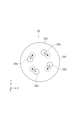
- FIG. 4 is a diagram showing the tip surface of the MCF 20.
- each MCF 20 has multiple cores 20a arranged at equal intervals around the central axis.
- Each MCF 20 has a cladding 20b that covers the multiple cores 20a.
- each MCF 20 has a tip portion 21 including a tip surface 20c, a coating portion 22, and a coating removal portion 23.
- the multiple MCFs 20 are held in each of the multiple fiber insertion holes 40.
- the multiple MCFs 20 are fixed to the ferrule 30 with an adhesive.
- the coating portion 22 has a plurality of cores 20a, a cladding 20b covering the plurality of cores 20a, and a resin coating covering the cladding.
- the tip portion 21 and the coating removal portion 23 are portions where a predetermined length of the resin coating has been removed from the tip surface 20c of each MCF 20 to expose the cladding 20b.
- the tip portion 21 extends from the tip surface 20c toward the introduction hole 35 along the Z direction.
- the coating removal portion 23 is continuous with the tip portion 21.
- the coating removal portion 23 extends along the Z direction to the first end 22a of the coating portion 22 in the Z direction.
- the coating portion 22 extends from the first end 22a along the Z direction.
- the ferrule 30 includes a ferrule body 31 configured to store multiple holding parts 10 and multiple MCFs 20 therein.
- the ferrule body 31 has a front end 32a (ferrule front end) and a rear end 32b (ferrule rear end) on the opposite side of the front end 32a in the Z direction.
- the ferrule body 31 includes a front end face 33 provided at the front end 32a and an opening 34 provided at the rear end 32b.
- the ferrule 30 further includes an introduction hole 35, multiple fiber insertion holes 40, a pair of guide holes 36, and a window 37.
- the front end face 33 intersects with the Z direction and is inclined with respect to a plane perpendicular to the Z direction. In the example shown in Fig. 2, the front end face 33 is flush with the tip face 20c of each MCF 20.
- the introduction hole 35 is provided in the ferrule body 31 from the rear end 32b toward the front end 32a.
- the introduction hole 35 extends, for example, from the opening 34 to the center position of the ferrule 30 in the Z direction.
- the introduction hole 35 is open at the opening 34.
- the cross section of the introduction hole 35 intersecting the Z direction is, for example, rectangular with the X direction as the longitudinal direction.
- the introduction hole 35 holds each holding part 10 together.
- the holding parts 10 are placed and positioned in the introduction hole 35.
- each of the multiple fiber insertion holes 40 extends from a portion 35a near the front end 32a of the introduction hole 35 to the front end 32a along the Z direction.
- the portion 35a near the front end 32a of the introduction hole 35 is closer to the front end 32a than the center position of the introduction hole 35 in the Z direction.
- Each of the multiple fiber insertion holes 40 holds multiple MCFs 20.
- the multiple fiber insertion holes 40 are configured to be able to hold the tip portions 21 of the multiple MCFs 20 respectively.
- the multiple fiber insertion holes 40 are arranged one-dimensionally or two-dimensionally on the front end surface 33.
- the multiple fiber insertion holes 40 are lined up along at least one of the X direction and the Y direction on the front end surface 33. For example, 16 fiber insertion hole rows lined up along the X direction are arranged in two rows along the Y direction.
- Each fiber insertion hole 40 holds the tip portion 21 of each MCF 20.
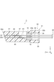
- FIG. 5 is a schematic cross-sectional view showing the cross-sectional shape of the fiber insertion hole 40.
- each of the multiple fiber insertion holes 40 has a fiber holding portion 41, an introduction portion 42, and a tapered portion 43 that connects the fiber holding portion 41 and the introduction portion 42.
- the fiber holding portion 41 extends from the front end 32a toward the introduction hole 35 along the Z direction.
- the fiber holding portion 41 is open at the front end 32a.
- the rear end of the fiber holding portion 41 is connected to the tapered portion 43.
- the fiber holding portion 41 has a constant inner diameter.
- the inner diameter of the fiber holding portion 41 corresponds to the outer diameter of the tip portion 21 of the MCF 20.
- the inner diameter of the fiber holding portion 41 is the same as the outer diameter of the tip portion 21 of the MCF 20 or is slightly larger than the outer diameter of the tip portion 21 of the MCF 20.
- the inner diameter of the fiber holding part 41 is, for example, 0.126 mm.
- the length of the fiber holding part 41 in the Z direction is, for example, 1.7 mm.
- the cross-sectional shape of the fiber holding part 41 intersecting the Z direction corresponds to the cross-sectional shape of the tip part 21 of the MCF 20, and is, for example, a circular shape.
- the introduction section 42 extends from the introduction hole 35 toward the front end 32a along the Z direction.
- the introduction section 42 is open at the introduction hole 35.
- the front end of the introduction section 42 is connected to the tapered section 43.
- the introduction section 42 has a constant inner diameter.
- the inner diameter of the introduction section 42 is larger than the inner diameter of the fiber holding section 41.
- the inner diameter of the introduction section 42 is larger than the outer diameter of the MCF 20.
- the inner diameter of the introduction section 42 is, for example, 2.0 mm.
- the length of the introduction section 42 in the Z direction is, for example, 1.0 mm.
- the cross-sectional shape of the introduction section 42 intersecting the Z direction corresponds to the cross-sectional shape of the tip 21 of the MCF 20, and is, for example, a circular shape.
- the tapered portion 43 has a tapered shape.
- the tapered portion 43 includes a front end 44 (tapered front end) and a rear end 45 (tapered rear end) on the opposite side of the front end 44 in the Z direction.
- the cross section along the center line axis L2 of the fiber insertion hole 40 and the inner surface 43a of the tapered portion 43 have two intersecting lines.
- the front end 44 and the rear end 45 are both ends in the Z direction of one of the two intersecting lines.
- the tapered portion 43 extends from the front end 44 to the rear end 45 along the Z direction.
- the ratio of the length of the tapered portion 43 to the length of the fiber insertion hole 40 in the Z direction may be 1/5 or more and 3/4 or less, or 2/5 or more and 2/3 or less, for example, 2/5.
- the length of the tapered portion 43 in the Z direction is, for example, 1.3 mm.
- the tapered portion 43 is connected to the fiber holding portion 41 at the front end 44. At the front end 44, the inner surface 43a of the tapered portion 43 is continuous with the inner surface 41a of the fiber holding portion 41.
- the inner diameter of the tapered portion 43 at the front end 44 is the same as the inner diameter of the fiber holding portion 41.
- the tapered portion 43 is connected to the introduction portion 42 at the rear end 45. At the rear end 45, the inner surface 43a of the tapered portion 43 is continuous with the inner surface 42a of the introduction portion 42. The inner diameter of the tapered portion 43 at the rear end 45 matches the inner diameter of the introduction portion 42.
- the inner diameter of the tapered portion 43 at the front end 44 is smaller than the inner diameter of the tapered portion 43 at the rear end 45.
- the inner diameter of the tapered portion 43 increases from the front end 44 to the rear end 45.
- the change in the inner diameter of the tapered portion 43 is constant.
- a straight line L1 (taper straight line) connecting the front end 44 and the rear end 45 of the tapered portion 43 coincides with the inner surface 43a of the tapered portion 43.
- the intersection line between the inner surface 43a of the tapered portion 43 and the cross section along the center line axis L2 is linear.
- the angle ⁇ 1 between the straight line L1 and the center line axis L2 of the fiber insertion hole 40 may be 1 degree or more and 14 degrees or less, or 5 degrees or more and 10 degrees or less, or may be, for example, 8 degrees.
- FIG. 6 is a flowchart showing a method for manufacturing the optical connector 1.
- the ferrule 30 is prepared (step S1). Also, a plurality of MCFs 20 are prepared (step S2).
- the corresponding MCF 20 among the multiple MCFs 20 is inserted into each of the multiple fiber insertion holes 40 (step S3).
- the coating removal parts 23 of the multiple MCFs 20 are placed in the multiple V-grooves of the holding part 10, and each MCF 20 is rotated and aligned around the central axis. At this time, each MCF 20 is rotated and aligned one by one with respect to the holding part 10.
- the holding part 10 and each MCF 20 are fixed via adhesive, and the multiple holding parts 10 are stacked in the Y direction.
- the adhesive is, for example, a UV-curable adhesive or a thermosetting adhesive.
- each holding part 10 is inserted into the introduction hole 35 of the ferrule 30.
- a certain degree of rotation can occur on the tip side of the holding part 10.
- the tip 21 of the MCF 20 with its rotational alignment temporarily fixed in this manner is inserted through the introduction hole 35 and then further inserted into the fiber insertion hole 40.
- the tapered portion 43 of the fiber insertion hole 40 has a gentle tapered shape as described above, so that axial misalignment is unlikely to occur when the MCF 20 (tip 21) temporarily fixed to the holding component 10 touches the inner surface of the fiber insertion hole 40. Therefore, the tip 21 of the MCF 20 is stored and held in the fiber holding portion 41 of the fiber insertion hole 40 with axial misalignment of the MCF 20 suppressed.
- the multiple MCFs 20 are fixed to the ferrule 30 (step S4).
- adhesive is introduced through the window 37 of the ferrule 30, and the multiple holding parts 10 and the multiple MCFs 20 are fixed to the ferrule 30 by the adhesive.
- a thermosetting adhesive is introduced through the window 37 provided in the upper part of the ferrule 30, and the adhesive is thermally cured to fix the fiber insertion hole 40 and the tip 21. In this manner, the optical connector shown in Figures 1 and 2 is produced.
- FIG. 7 is a schematic diagram showing a fiber insertion hole of a conventional ferrule.
- Figures 8 and 9 are schematic diagrams for explaining the case where an MCF 20 is inserted into a conventional fiber insertion hole.
- the angle ⁇ 2 between the center line axis L4 of the fiber insertion hole 1040 and the straight line L3 connecting the front end 44 and the rear end 45 of the tapered portion 1043 in a cross section taken along the center line axis L4 is 15 degrees or more and 20 degrees or less.
- the MCF 20 After being guided to the introduction portion 42, the MCF 20 comes into strong contact with the inner surface of the tapered portion 1043 and is guided to the fiber holding portion 41 while receiving a frictional force from the inner surface of the tapered portion 1043 (it is aligned in the direction of the fiber holding portion 41). As shown in Figure 9, this frictional force causes the MCF 20 to rotate at the tapered portion 1043, and the position of the core 20a of the MCF 20 shifts along the circumferential direction of the MCF 20. If the MCF 20 is fixed in this shifted state to form the optical connector 1, the optical coupling efficiency between the MCF 20 of this optical connector 1 and the MCF held in another ferrule will decrease.
- the angle between the centerline axis L2 of each of the multiple fiber insertion holes 40 and the straight line L1 connecting the front end 44 and the rear end 45 of the tapered portion 43 in the cross section along the centerline axis L2 is 1 degree or more and 14 degrees or less, and the shape of the tapered portion 43 is a gentle tapered shape.
- the frictional force received from the inner surface 43a of the tapered portion 43 when the MCF 20 is inserted into the fiber insertion hole 40 and contacts the inner surface 43a of the tapered portion 43 is reduced compared to a ferrule having a conventional fiber insertion hole 1040.
- the MCF 20 when the MCF 20 is inserted into the fiber insertion hole 40, the MCF 20 is prevented from rotating and causing a circumferential shift (axial shift) of the multiple cores 20a of the MCF 20 (is less likely to rotate).
- the axial misalignment of the MCF 20 is suppressed, thereby suppressing a decrease in the optical coupling efficiency between the MCF 20 and the MCF 20 of another ferrule 30.
- the straight line L1 coincides with the inner surface 43a of the tapered portion 43.
- the inner surface 43a of the tapered portion 43 is flat, the MCF 20 in contact with the inner surface 43a of the tapered portion 43 is further prevented from rotating and causing axial misalignment.
- axial misalignment of the MCF 20 is further suppressed, thereby further suppressing a decrease in the optical coupling efficiency between the MCF 20 and MCFs 20 held in other ferrules 30.
- each of the multiple fiber insertion holes 40 further has an introduction portion 42.
- the introduction portion 42 extends from the introduction hole 35 along the Z direction and communicates with the tapered portion 43 at the rear end 45.
- the introduction portion 42 has a constant inner diameter.
- the introduction portion 42 that first receives the MCF 20 introduced from the introduction hole 35 has a constant inner diameter, the MCF 20 can be inserted into the fiber insertion hole 40 while preventing the MCF 20 from contacting the inner surface 42a of the introduction portion 42.
- the MCF 20 is further prevented from rotating and causing axial misalignment when the MCF 20 is inserted into the fiber insertion hole 40.
- the ratio of the length of the tapered portion 43 to the length of each of the multiple fiber insertion holes 40 in the Z direction is 1/5 or more and 3/4 or less.
- the above length ratio is 3/4 or less, it is possible to make the fiber holding portion 41 of the fiber insertion hole 40 sufficiently long in the Z direction. This allows each fiber holding portion 41 to stably support each MCF 20.
- the above length ratio is 1/5 or more, it is possible to make the tapered portion 43 sufficiently long in the Z direction.
- the angle between the center line axis L2 of each of the multiple fiber insertion holes 40 and the straight line L1 in the cross section along the center line axis L2 may be 5 degrees or more and 10 degrees or less.
- rotation of the MCF 20 and axial misalignment caused when the MCF 20 is inserted into the fiber insertion hole 40 is further suppressed.
- axial misalignment of the MCF 20 is further suppressed, thereby further suppressing a decrease in optical coupling efficiency between the MCF 20 and MCFs 20 held in other ferrules 30.
- the inner diameter of the introduction section 42 is larger than the inner diameter of the fiber holding section 41. In this case, it is possible for each fiber holding section 41 to stably hold the tip section 21 of each MCF 20, while improving the ease of inserting the MCF 20 into the introduction section 42.
- the optical connector 1 includes a ferrule 30 and a plurality of MCFs 20 each having a plurality of cores 20a.
- the plurality of MCFs 20 are held in each of a plurality of fiber insertion holes 40.
- the plurality of MCFs 20 are fixed to the above-mentioned ferrule 30. This configuration prevents the MCF 20 from rotating and causing axial misalignment when the MCF 20 is inserted into the fiber insertion hole 40. This prevents axial misalignment of the MCF 20 when inserting an MCF 20 that requires rotational alignment into the ferrule 30, thereby preventing a decrease in optical coupling efficiency between the MCF 20 and MCFs 20 held in other ferrules 30.
- the manufacturing method of the optical connector 1 includes the steps of preparing a ferrule 30, preparing a plurality of MCFs 20 each having a plurality of cores 20a, and inserting a corresponding one of the plurality of MCFs 20 into each of the plurality of fiber insertion holes 40.
- a ferrule 30 having a fiber insertion hole 40 with a gentle tapered shape is used, and the MCF 20 is inserted into such a fiber insertion hole 40. This further suppresses the MCF 20 from rotating and causing axial misalignment.
- a plurality of MCFs 20 are inserted into a plurality of fiber insertion holes 40, but the present invention is not limited to this.
- a plurality of optical fibers 20 are inserted into the plurality of fiber insertion holes 40, and the optical fibers 20 may be optical fibers that require rotational alignment.
- the optical fiber 20 may be either a polarization-maintaining fiber or a bundle fiber, or may be other optical fibers other than those described above.
- the optical fiber 20 is an optical fiber that requires rotational alignment, when the optical fiber 20 is inserted into the ferrule 30, the axial misalignment of the optical fiber 20 is suppressed, thereby suppressing a decrease in the optical coupling efficiency between the optical fiber 20 and the optical fiber 20 held in the other ferrule 30.
- the ferrule 30 has multiple fiber insertion holes 40, but this is not limited to this.
- Figures 10 to 12 are schematic diagrams showing various shapes of fiber insertion holes of ferrules 30 according to modified examples.
- the fiber insertion hole 140 does not have the introduction portion 42. That is, the fiber insertion hole 140 is configured to have only the fiber holding portion 41 and the tapered portion 143.
- the fiber holding portion 41 extends from the front end 32a toward the introduction hole 35 along the Z direction.
- the tapered portion 143 communicates with the fiber holding portion 41 at the front end 44.
- the tapered portion 143 extends from the front end 44 to the rear end 45 along the Z direction.
- the tapered portion 143 communicates with the introduction hole 35 at the rear end 45.
- the inner diameter of the tapered portion 143 at the front end 44 is smaller than the inner diameter of the tapered portion 143 at the rear end 45.
- the inner diameter of the tapered portion 143 increases from the front end 44 toward the rear end 45.
- the change in the inner diameter of the tapered portion 143 is constant.
- the angle ⁇ 3 between a straight line L5 (taper straight line) connecting the front end 44 and the rear end 45 of the tapered portion 143 in a cross section taken along the centerline axis L6 of the fiber insertion hole 140 and the centerline axis L6 of the fiber insertion hole 140 is the same as the angle ⁇ 1 in the above embodiment.
- the straight line L5 coincides with the inner surface 143a of the tapered portion 143.
- the intersection line between the inner surface 143a of the tapered portion 143 and the cross section taken along the centerline axis L6 is linear.
- a fiber insertion hole 240 has a fiber holding portion 41, an introduction portion 42, and a tapered portion 243 connecting the fiber holding portion 41 and the introduction portion 42.
- the inner diameter of the tapered portion 243 at the front end 44 is smaller than the inner diameter of the tapered portion 243 at the rear end 45.
- the inner diameter of the tapered portion 243 increases from the front end 44 toward the rear end 45.
- the change in the inner diameter of the tapered portion 243 is not constant.
- the inclination of the inner surface 243a of the tapered portion 243 becomes gentler as it approaches the front end 44 (the gradient of the inner surface 243a changes continuously toward the front end 44).
- a virtual straight line L7 tapeer straight line
- the angle between the tangent at the contact point on the inner surface 243a of the tapered portion 243 and the center line axis L8 of the fiber insertion hole 240 decreases as the contact point approaches the front end 44 in the Z direction.
- the inner surface 243a of the tapered portion 243 is continuous with the inner surface 41a of the fiber holding portion 41.
- the inner surface 243a of the tapered portion 243 is flush with the inner surface 41a of the fiber holding portion 41.
- the angle ⁇ 4 between the virtual straight line L7 in the cross section taken along the center line axis L8 of the fiber insertion hole 240 and the center line axis L8 of the fiber insertion hole 240 is the same as the angle ⁇ 1 in the above embodiment.
- the angle between the tangent at the contact point on the inner surface 243a of the tapered portion 243 and the center line axis L8 of the fiber insertion hole 240 decreases as the contact point approaches the front end 44 in the Z direction.
- the inclination of the inner surface 243a of the tapered portion 243 becomes gentler as it approaches the front end 44 of the tapered portion 243. This makes it possible to further reduce the friction force that the MCF 20 receives from the inner surface 243a of the tapered portion 243 near the front end 44 of the tapered portion 243.
- the inner diameter at the rear end 45 of the tapered portion 243 can be made larger without changing the length of the tapered portion 243 in the Z direction. This prevents the MCF 20 from contacting the inner surface 243a of the tapered portion 243 near the rear end 45 when the MCF 20 is inserted into the fiber insertion hole 40. From the above, the MCF 20 is further prevented from rotating and causing axial misalignment when it is inserted into the fiber insertion hole 40. As a result, when an MCF 20 that requires rotational alignment is inserted into a ferrule 30, axial misalignment of the MCF 20 is further suppressed, which further suppresses the decrease in optical coupling efficiency between the MCF 20 and MCFs 20 held in other ferrules 30.
- the fiber insertion hole 340 according to the third modification does not have the introduction portion 42.
- This fiber insertion hole 340 is configured to have only the fiber holding portion 41 and the tapered portion 343.
- the tapered portion 343 extends from the front end 32a toward the introduction hole 35 along the Z direction.
- the tapered portion 343 communicates with the fiber holding portion 41 at the front end 44.
- the tapered portion 343 extends from the front end 44 to the rear end 45 along the Z direction.
- the tapered portion 343 communicates with the introduction hole 35 at the rear end 45.
- the inner diameter of the tapered portion 343 at the front end 44 is smaller than the inner diameter of the tapered portion 343 at the rear end 45.
- the inner diameter of the tapered portion 343 increases from the front end 44 to the rear end 45.
- the change in the inner diameter of the tapered portion 343 is not constant.
- the inner surface 343a of the tapered portion 343 may become more gentle as it approaches the front end 44 (the gradient of the inner surface 343a may change continuously toward the front end 44).
- the angle ⁇ 5 between the center line axis L10 of the fiber insertion hole 340 and the imaginary line L9 (taper line) connecting the front end 44 and the rear end 45 of the tapered portion 343 in the cross section along the center line axis L10 is the same angle as the angle ⁇ 1 in the above embodiment.
- the angle between the tangent at the contact point on the inner surface 343a of the tapered portion 343 and the center line axis L10 of the fiber insertion hole 340 may decrease as the contact point approaches the front end 44 in the Z direction.
- the inner surface 343a of the tapered portion 343 is continuous with the inner surface 41a of the fiber holding portion 41 at the front end 44.
- the inner surface 343a of the tapered portion 343 is flush with the inner surface 41a of the fiber holding portion 41 at the front end 44.
Landscapes
- Physics & Mathematics (AREA)
- General Physics & Mathematics (AREA)
- Optics & Photonics (AREA)
- Mechanical Coupling Of Light Guides (AREA)
Priority Applications (3)
| Application Number | Priority Date | Filing Date | Title |
|---|---|---|---|
| JP2025502176A JPWO2024176680A1 (https=) | 2023-02-21 | 2024-01-22 | |
| EP24759987.1A EP4671838A1 (en) | 2023-02-21 | 2024-01-22 | FERRULE, OPTICAL CONNECTOR AND METHOD FOR MANUFACTURING OPTICAL CONNECTORS |
| CN202480013513.8A CN120731388A (zh) | 2023-02-21 | 2024-01-22 | 插芯、光连接器以及光连接器的制造方法 |
Applications Claiming Priority (2)
| Application Number | Priority Date | Filing Date | Title |
|---|---|---|---|
| JP2023025311 | 2023-02-21 | ||
| JP2023-025311 | 2023-02-21 |
Publications (1)
| Publication Number | Publication Date |
|---|---|
| WO2024176680A1 true WO2024176680A1 (ja) | 2024-08-29 |
Family
ID=92500655
Family Applications (1)
| Application Number | Title | Priority Date | Filing Date |
|---|---|---|---|
| PCT/JP2024/001663 Ceased WO2024176680A1 (ja) | 2023-02-21 | 2024-01-22 | フェルール、光コネクタ、及び光コネクタの製造方法 |
Country Status (4)
| Country | Link |
|---|---|
| EP (1) | EP4671838A1 (https=) |
| JP (1) | JPWO2024176680A1 (https=) |
| CN (1) | CN120731388A (https=) |
| WO (1) | WO2024176680A1 (https=) |
Citations (10)
| Publication number | Priority date | Publication date | Assignee | Title |
|---|---|---|---|---|
| JPH07253521A (ja) * | 1993-09-27 | 1995-10-03 | Toto Ltd | 光ファイバコネクタ用キャピラリ及びその製造方法 |
| JPH09133837A (ja) * | 1995-09-08 | 1997-05-20 | Seiko Seiki Co Ltd | 光ファイバコネクタと、光ファイバコネクタ用フェルール及びその製造方法 |
| JP2002311290A (ja) * | 2000-08-21 | 2002-10-23 | Seiko Instruments Inc | フェルール射出成形用金型およびフェルール成形素材 |
| JP3455692B2 (ja) * | 1999-03-09 | 2003-10-14 | 住友電気工業株式会社 | 光コネクタ用フェルール |
| JP2005338517A (ja) * | 2004-05-27 | 2005-12-08 | Kyocera Corp | 光コネクタ用フェルール及び成形コアピン |
| JP2007163626A (ja) | 2005-12-12 | 2007-06-28 | Furukawa Electric Co Ltd:The | 光コネクタ |
| JP2009151338A (ja) * | 2009-04-03 | 2009-07-09 | Furukawa Electric Co Ltd:The | フェルール |
| WO2016031678A1 (ja) * | 2014-08-29 | 2016-03-03 | 古河電気工業株式会社 | 多心コネクタ、コネクタおよびコネクタ接続構造 |
| WO2018135368A1 (ja) * | 2017-01-17 | 2018-07-26 | 住友電気工業株式会社 | 光ファイバ保持部品、光コネクタ、及び光結合構造 |
| JP2023025311A (ja) | 2020-02-05 | 2023-02-22 | 味の素株式会社 | タンパク質の製造方法 |
-
2024
- 2024-01-22 EP EP24759987.1A patent/EP4671838A1/en active Pending
- 2024-01-22 WO PCT/JP2024/001663 patent/WO2024176680A1/ja not_active Ceased
- 2024-01-22 CN CN202480013513.8A patent/CN120731388A/zh active Pending
- 2024-01-22 JP JP2025502176A patent/JPWO2024176680A1/ja active Pending
Patent Citations (10)
| Publication number | Priority date | Publication date | Assignee | Title |
|---|---|---|---|---|
| JPH07253521A (ja) * | 1993-09-27 | 1995-10-03 | Toto Ltd | 光ファイバコネクタ用キャピラリ及びその製造方法 |
| JPH09133837A (ja) * | 1995-09-08 | 1997-05-20 | Seiko Seiki Co Ltd | 光ファイバコネクタと、光ファイバコネクタ用フェルール及びその製造方法 |
| JP3455692B2 (ja) * | 1999-03-09 | 2003-10-14 | 住友電気工業株式会社 | 光コネクタ用フェルール |
| JP2002311290A (ja) * | 2000-08-21 | 2002-10-23 | Seiko Instruments Inc | フェルール射出成形用金型およびフェルール成形素材 |
| JP2005338517A (ja) * | 2004-05-27 | 2005-12-08 | Kyocera Corp | 光コネクタ用フェルール及び成形コアピン |
| JP2007163626A (ja) | 2005-12-12 | 2007-06-28 | Furukawa Electric Co Ltd:The | 光コネクタ |
| JP2009151338A (ja) * | 2009-04-03 | 2009-07-09 | Furukawa Electric Co Ltd:The | フェルール |
| WO2016031678A1 (ja) * | 2014-08-29 | 2016-03-03 | 古河電気工業株式会社 | 多心コネクタ、コネクタおよびコネクタ接続構造 |
| WO2018135368A1 (ja) * | 2017-01-17 | 2018-07-26 | 住友電気工業株式会社 | 光ファイバ保持部品、光コネクタ、及び光結合構造 |
| JP2023025311A (ja) | 2020-02-05 | 2023-02-22 | 味の素株式会社 | タンパク質の製造方法 |
Non-Patent Citations (1)
| Title |
|---|
| See also references of EP4671838A1 |
Also Published As
| Publication number | Publication date |
|---|---|
| JPWO2024176680A1 (https=) | 2024-08-29 |
| CN120731388A (zh) | 2025-09-30 |
| EP4671838A1 (en) | 2025-12-31 |
Similar Documents
| Publication | Publication Date | Title |
|---|---|---|
| JP7040464B2 (ja) | 光ファイバ保持部品、光コネクタ、及び光結合構造 | |
| EP3734339B1 (en) | Optical connector and optical connection structure | |
| US4919509A (en) | Mechanical connection for polarization-maintaining optical fiber and methods of making | |
| WO2023199632A1 (ja) | 光ファイバ保持部品、光ファイバ結合構造体、光コネクタ、及び光結合構造 | |
| WO2024176680A1 (ja) | フェルール、光コネクタ、及び光コネクタの製造方法 | |
| JP7388368B2 (ja) | フェルール及び光コネクタ | |
| JPWO2024176680A5 (https=) | ||
| JP3843842B2 (ja) | 光コネクタ用フェルール | |
| WO2024142472A1 (ja) | 光ファイバ保持部品およびフェルールアセンブリ | |
| WO2024171993A1 (ja) | 光コネクタおよび光コネクタの製造方法 | |
| US20260016643A1 (en) | Optical connector, ferrule, and optical coupling structure | |
| US10578811B2 (en) | Methods of forming ferrules for optical fiber connectors, and optical fiber cable assemblies related to such methods | |
| JP6930170B2 (ja) | 光接続部品の製造方法 | |
| JP7784453B2 (ja) | バンドルファイバコネクタ及びファイバコネクタの製造方法 | |
| WO2024147241A1 (ja) | 光コネクタフェルール、光コネクタ、及び光結合構造 | |
| US20020102068A1 (en) | Ferrule for optical connector | |
| WO2024252931A1 (ja) | 光ファイバ保持部品、光ファイバアセンブリ、光コネクタ、および光結合デバイス | |
| JPWO2024029270A5 (https=) | ||
| CN118056148A (zh) | 光连接器 | |
| JP2026031202A (ja) | フェルール、光コネクタおよびフェルールの製造方法 | |
| WO2025075062A1 (ja) | 光コネクタ、光接続アセンブリ、および光コネクタの製造方法 | |
| WO2025239152A1 (ja) | 光コネクタ | |
| JP2026023810A (ja) | フェルールおよび光コネクタ | |
| CN121359061A (zh) | 光纤保持部件、光纤耦合结构体、光连接器、光耦合结构以及光纤耦合结构体的制造方法 | |
| JP2024106690A5 (https=) |
Legal Events
| Date | Code | Title | Description |
|---|---|---|---|
| 121 | Ep: the epo has been informed by wipo that ep was designated in this application |
Ref document number: 24759987 Country of ref document: EP Kind code of ref document: A1 |
|
| ENP | Entry into the national phase |
Ref document number: 2025502176 Country of ref document: JP Kind code of ref document: A |
|
| WWE | Wipo information: entry into national phase |
Ref document number: 2025502176 Country of ref document: JP |
|
| WWE | Wipo information: entry into national phase |
Ref document number: 202480013513.8 Country of ref document: CN |
|
| WWE | Wipo information: entry into national phase |
Ref document number: 2024759987 Country of ref document: EP |
|
| NENP | Non-entry into the national phase |
Ref country code: DE |
|
| WWP | Wipo information: published in national office |
Ref document number: 202480013513.8 Country of ref document: CN |
|
| ENP | Entry into the national phase |
Ref document number: 2024759987 Country of ref document: EP Effective date: 20250922 |
|
| ENP | Entry into the national phase |
Ref document number: 2024759987 Country of ref document: EP Effective date: 20250922 |
|
| WWP | Wipo information: published in national office |
Ref document number: 2024759987 Country of ref document: EP |