WO2024176556A1 - 摩擦ディスク、多板クラッチ、トランスミッション、および作業機械 - Google Patents
摩擦ディスク、多板クラッチ、トランスミッション、および作業機械 Download PDFInfo
- Publication number
- WO2024176556A1 WO2024176556A1 PCT/JP2023/042568 JP2023042568W WO2024176556A1 WO 2024176556 A1 WO2024176556 A1 WO 2024176556A1 JP 2023042568 W JP2023042568 W JP 2023042568W WO 2024176556 A1 WO2024176556 A1 WO 2024176556A1
- Authority
- WO
- WIPO (PCT)
- Prior art keywords
- groove
- inlet
- circumferential direction
- path
- lubricating oil
- Prior art date
- Legal status (The legal status is an assumption and is not a legal conclusion. Google has not performed a legal analysis and makes no representation as to the accuracy of the status listed.)
- Ceased
Links
Images






Classifications
-
- F—MECHANICAL ENGINEERING; LIGHTING; HEATING; WEAPONS; BLASTING
- F16—ENGINEERING ELEMENTS AND UNITS; GENERAL MEASURES FOR PRODUCING AND MAINTAINING EFFECTIVE FUNCTIONING OF MACHINES OR INSTALLATIONS; THERMAL INSULATION IN GENERAL
- F16D—COUPLINGS FOR TRANSMITTING ROTATION; CLUTCHES; BRAKES
- F16D13/00—Friction clutches
- F16D13/58—Details
- F16D13/60—Clutching elements
- F16D13/62—Clutch-bands; Clutch shoes; Clutch-drums
Definitions
- the present invention relates to a friction disc, a multi-plate clutch, a transmission, and a work machine.
- Multi-plate clutches have multiple friction discs and multiple separator plates, and shift speeds by controlling rotational motion by engaging or disengaging the friction discs and separator plates.
- Patent Document 1 there is a demand for further reduction in power transmission loss, and the structure shown in Patent Document 1 above does not sufficiently reduce drag torque.
- An object of the present disclosure is to provide a friction disc, a multi-plate clutch, a transmission, and a work machine that are capable of further reducing drag torque. (Means for solving the problem)
- the friction disc of the first aspect of the present disclosure is a friction disc used in a power transmission device, and includes a lubricating oil groove through which lubricating oil passes.
- the lubricating oil groove has a plurality of first groove paths and a plurality of second groove paths.
- the plurality of first groove paths are formed on the surface in a line in the circumferential direction.
- the plurality of second groove paths are formed on the surface in a line in the circumferential direction.
- Each of the first groove paths has a first inlet, a second outlet, and a first A groove portion.
- the first inlet is disposed on the inner peripheral edge side, through which the lubricating oil flows in.
- the first outlet is disposed on the outer peripheral edge side, through which the lubricating oil flows out.
- the first A groove portion is formed from the first inlet and is inclined toward the first circumferential direction side in the circumferential direction with respect to the radial direction.
- Each of the second groove paths is disposed on the inner peripheral edge side, has a second inlet through which the lubricating oil flows in, is inclined toward the second circumferential direction side opposite the first circumferential direction with respect to the radial direction, and merges with the first A groove portion.
- the junction where the second groove path joins the first A groove portion forms a three-way intersection and is located between the first inlet and first outlet of the first groove path, closer to the first inlet.
- a friction disk according to a second aspect of the present disclosure is a friction disk used in a power transmission device, and includes a lubricant groove through which a lubricant passes.
- the lubricant groove has a plurality of third groove paths and a plurality of fourth groove paths.
- the plurality of third groove paths are formed on the surface in a line in the circumferential direction.
- the fourth groove path is formed on the surface in a line in the circumferential direction.
- Each of the third groove paths has a third inlet, a second outlet, and a third A groove portion.
- the third inlet is disposed on the inner peripheral edge side, through which the lubricant flows in.
- the second outlet is disposed on the outer peripheral edge side, through which the lubricant flows out.
- the third A groove portion is formed from the third inlet, and is inclined toward the second circumferential direction side of the circumferential direction with respect to the radial direction.
- Each of the fourth groove paths branches off from the third A groove portion, and is inclined toward the first circumferential direction side opposite to the second circumferential direction with respect to the radial direction.
- the branching portion where the fourth groove path branches off from the thirdA groove portion forms a three-way intersection and is disposed between the third inlet and the second outlet of the third groove path, closer to the third inlet.
- the present disclosure provides a friction disc, a multi-plate clutch, a transmission, and a work machine that can further reduce drag torque.
- FIG. 1 is a perspective view showing a bulldozer according to an embodiment of the present disclosure.
- 1 is a diagram showing a configuration of a power transmission device of a bulldozer according to an embodiment of the present disclosure.
- FIG. 2 is a diagram showing a configuration of a transmission of a bulldozer according to an embodiment of the present disclosure.
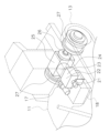
- FIG. 2 is a partial perspective view of a reverse clutch for a bulldozer according to an embodiment of the present disclosure.
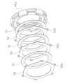
- FIG. 5 is an exploded perspective view of FIG. 4 .
- FIG. 2 is a perspective view of a friction disk according to an embodiment of the present disclosure.
- FIG. 2 is a partially enlarged perspective view of a friction disk according to an embodiment of the present disclosure.
- FIG. 1 is a perspective view showing a bulldozer according to an embodiment of the present disclosure.
- 1 is a diagram showing a configuration of a power transmission device of a bulldozer according to an embodiment of the present disclosure.
- FIG. 2
- FIG. 2 is a plan view of a friction disk according to an embodiment of the present disclosure.
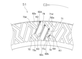
- FIG. 2 is a partially enlarged plan view of a friction disk according to an embodiment of the present disclosure.
- FIG. 2 is a schematic diagram of a friction disc according to an embodiment of the present disclosure, showing an inner circumference, an outer circumference, a curve, and an inner peripheral edge.
- FIG. 2 is a plan view illustrating a flow of lubricant oil when a friction disc in an embodiment according to the present disclosure is rotated in a first circumferential direction.
- FIG. 13 is a plan view illustrating the flow of lubricant oil when the friction disc in the embodiment disclosed herein is rotated in a second circumferential direction.
- 1A is an enlarged plan view showing a friction disk of Comparative Example 1, FIG.
- FIG. 1B is an enlarged plan view showing a friction disk of Comparative Example 2
- FIG. 1C is an enlarged plan view showing a friction disk of Comparative Example 3.
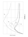
- FIG. 11 is a graph showing the change in drag torque with respect to the rotation speed in an example and comparative examples 1 to 3.
- the friction disc, multi-plate clutch, transmission, and work machine of the embodiment disclosed herein will be described with reference to the drawings.
- the friction disc of this embodiment is used, for example, in the drive system of the work machine.
- ⁇ Configuration> 1 is a perspective view of a bulldozer 1, which is an example of a work machine according to the present disclosure.
- the bulldozer 1 includes a vehicle body 11 and a work implement 12.
- the vehicle body 11 has tracks 13. Power from an engine is transmitted to rotate the tracks 13, causing the bulldozer 1 to travel.
- the work machine 12 is attached to the vehicle body 11.
- the work machine 12 includes a lift frame 14, a blade 15, and a lift cylinder 16.
- the lift frame 14 is attached to the vehicle body 11 so as to be movable up and down.
- the lift frame 14 supports the blade 15.
- the blade 15 moves up and down in conjunction with the movement of the lift frame 14.
- the lift cylinder 16 is connected to the vehicle body 11 and the lift frame 14.
- the lift cylinder 16 extends and retracts, causing the lift frame 14 to move up and down.
- FIG. 2 is a schematic diagram for explaining the configuration of the power transmission device 17 of the bulldozer 1.
- the bulldozer 1 has the power transmission device 17.
- the power transmission device 17 transmits power from the engine 18 to the tracks 13.
- the power transmission device 17 has a universal joint 21, a torque converter 22, a power take-off 23, a transmission 24, an HSS (Hydrostatic Steering system) 25, a horizontal shaft 26, and a final drive 27.
- HSS Hydrostatic Steering system
- the universal joint 21 transmits the power from the engine 18 to the torque converter 22.
- the universal joint 21 outputs the power from the engine 18 to the power take-off 23.
- the power take-off 23 outputs the power from the engine 18 to a hydraulic oil pump that supplies hydraulic oil to the lift cylinder 16.
- the torque converter 22 outputs the power of the engine 18, which is input via the universal joint 21, to the transmission 24.
- the transmission 24 changes the gear ratio when the vehicle body 11 switches between forward and reverse, and when the vehicle is in forward or reverse.
- the HSS 25 has a steering pump, steering motor, steering planetary mechanism, etc., and turns the vehicle by creating a difference in left and right output rotations using the differential mechanism of the planetary gear train, which uses the linear power from the transmission 24 and the turning power from the hydraulic motor.
- the horizontal shaft 26 transmits the power from the HSS 25 to the final drive 27.
- the final drives 27 are arranged on the left and right, and the tracks 13 are wrapped around them. The rotation of the final drive 27 rotates the tracks 13, causing the vehicle body 11 to move.
- Transmission 24 3 is a diagram showing the configuration of the transmission 24.
- the transmission 24 has a case 31, an input shaft 32, an output shaft 33, a reverse planetary gear mechanism 34, a forward planetary gear mechanism 35, a first-speed planetary gear mechanism 36, a second-speed planetary gear mechanism 37, a third-speed planetary gear mechanism 38, a reverse clutch 41, a forward clutch 42, a first-speed clutch 43, a second-speed clutch 44, and a third-speed clutch 45.
- the input shaft 32 transmits power from the torque converter 22.
- the input shaft 32 is rotatably supported by the case 31.
- the output shaft 33 transmits an output, the rotation direction and gear ratio of which have been controlled, to the HSS 25.
- the output shaft 33 is disposed coaxially with the input shaft 32.
- the reverse planetary gear mechanism 34 is arranged around the input shaft 32. In the power transmission direction, the reverse planetary gear mechanism 34 is arranged on the most upstream side.
- the reverse planetary gear mechanism 34 has a reverse sun gear 34a, a reverse carrier 34b, a reverse ring gear 34c, and multiple reverse planetary gears 34d.
- the reverse sun gear 34a is fixed to the input shaft 32.
- the reverse carrier 34b rotatably supports multiple reverse planetary gears 34d arranged at approximately equal intervals in the circumferential direction.
- the multiple reverse planetary gears 34d are each meshed with the reverse sun gear 34a.
- the reverse ring gear 34c is arranged on the outer periphery of the multiple reverse planetary gears 34d journaled on the reverse carrier 34b, and meshes with the multiple reverse planetary gears 34d.
- the forward planetary gear mechanism 35 is arranged around the input shaft 32. In the power transmission direction, the forward planetary gear mechanism 35 is arranged downstream of the reverse planetary gear mechanism 34.
- the forward planetary gear mechanism 35 has a forward sun gear 35a, a forward carrier 35b, a forward ring gear 35c, and multiple forward planetary gears 35d.
- the forward sun gear 35a is fixed to the input shaft 32.
- the forward carrier 35b rotatably supports multiple forward planetary gears 35d arranged at approximately equal intervals in the circumferential direction.
- the multiple forward planetary gears 35d are each meshed with the forward sun gear 35a.
- the forward ring gear 35c is arranged on the outer periphery of the multiple forward planetary gears 35d journaled on the forward carrier 35b, and meshes with the multiple forward planetary gears 35d.
- the first-speed planetary gear mechanism 36 is arranged around the output shaft 33.
- the first-speed planetary gear mechanism 36 is arranged at the most downstream side of the output shaft 33 in the power transmission direction.
- the first-speed planetary gear mechanism 36 has a first-speed sun gear 36a, a first-speed carrier 36b, a first-speed ring gear 36c, and a plurality of first-speed planetary gears 36d.
- the first-speed sun gear 36a is fixed to the output shaft 33.
- the first-speed carrier 36b rotatably supports a plurality of first-speed planetary gears 36d arranged at approximately equal intervals in the circumferential direction.
- the multiple first-speed planetary gears 36d are each meshed with the first-speed sun gear 36a.
- the first-speed ring gear 36c is disposed on the outer periphery of a plurality of first-speed planetary gears 36d journaled on the first-speed carrier 36b, and is in mesh with the plurality of first-speed planetary gears 36d.
- the second-speed planetary gear mechanism 37 is arranged around the output shaft 33.
- the second-speed planetary gear mechanism 37 is arranged upstream of the first-speed planetary gear mechanism 36 in the power transmission direction.
- the second-speed planetary gear mechanism 37 has a second-speed sun gear 37a, a second-speed and third-speed carrier 37b, a second-speed ring gear 37c, and a plurality of second-speed planetary gears 37d.
- the second-speed sun gear 37a is fixed to the output shaft 33.
- the second-speed and third-speed carrier 37b rotatably supports a plurality of second-speed planetary gears 37d arranged at approximately equal intervals in the circumferential direction.
- the multiple second-speed planetary gears 37d are each meshed with the second-speed sun gear 37a.
- the second-speed ring gear 37c is disposed on the outer periphery of multiple second-speed planetary gears 37d journaled on the second-speed/third-speed carrier 37b, and is engaged with the multiple second-speed planetary gears 37d.
- the third-speed planetary gear mechanism 38 is arranged around the output shaft 33.
- the third-speed planetary gear mechanism 38 is arranged upstream of the second-speed planetary gear mechanism 37 in the power transmission direction.
- the third-speed planetary gear mechanism 38 has a third-speed sun gear 38a, a second-speed/third-speed carrier 37b, a third-speed ring gear 38c, and a plurality of third-speed planetary gears 38d.
- the third-speed sun gear 38a is fixed to the output shaft 33.
- the second-speed/third-speed carrier 37b rotatably supports a plurality of third-speed planetary gears 38d arranged at approximately equal intervals in the circumferential direction.
- the second-speed/third-speed carrier 37b also serves as a planetary carrier for both the second-speed planetary gear mechanism 37 and the third-speed planetary gear mechanism 38.
- the plurality of third-speed planetary gears 38d are each meshed with the third-speed sun gear 38a.
- the third-speed ring gear 38c is disposed on the outer periphery of a plurality of third-speed planetary gears 38d journaled on the second-speed/third-speed carrier 37b, and is engaged with the plurality of third-speed planetary gears 38d.
- forward planetary gear mechanism 34 the forward planetary gear mechanism 35, the first-speed planetary gear mechanism 36, the second-speed planetary gear mechanism 37, and the third-speed planetary gear mechanism 38 correspond to examples of power transmission mechanisms.
- the reverse clutch 41 is disposed on the outer periphery of the reverse planetary gear mechanism 34.
- the reverse clutch 41 fixes or releases the reverse carrier 34b to the case 31.
- the output shaft 33 can be rotated in the opposite direction relative to the input shaft 32 to move the bulldozer 1 in reverse.
- the reverse clutch 41 has a plurality of friction discs 51, a plurality of separator plates 52, a reverse clutch housing 41a, and a piston 41b.
- Figure 4 is a partial perspective view of the reverse clutch 41.
- Figure 5 is an exploded perspective view of Figure 4.
- Figures 4 and 5 show a portion of the reverse clutch housing 41a.
- the friction disc 51 is annular.
- the friction disc 51 is arranged to be rotatable.
- the separator plate 52 is annular.
- the separator plate 52 has a protrusion 52a on its outer periphery and is fixed to the case 31.
- the friction disc 51 rotates together with the reverse carrier 34b.
- the friction discs 51 and the separator plates 52 are arranged alternately along the axial direction of the input shaft 32.
- the reverse clutch housing 41a houses a plurality of friction discs 51 and a plurality of separator plates 52.
- the piston 41b presses the separator plates 52 and the friction discs 51 against the reverse clutch housing 41a along the axial direction of the input shaft 32.
- a gap d1 is provided between the separator plates 52 and the friction discs 51, and the friction discs 51 can rotate together with the reverse carrier 34b.
- the configuration of the friction discs 51 will be described in detail later.
- the forward clutch 42 is disposed on the outer periphery of the forward planetary gear mechanism 35.
- the forward clutch 42 fixes or releases the forward ring gear 35c to the case 31.
- the output shaft 33 can be rotated in the same direction as the input shaft 32 to move the bulldozer 1 forward.
- the forward clutch 42 like the reverse clutch 41, has multiple friction discs 51, multiple separator plates 52, a forward clutch housing 42a, and a piston 42b.
- the forward clutch 42 has a different number of friction discs 51 and separator plates 52, but has the same configuration as the reverse clutch 41, so a description of the forward clutch housing 42a and piston 42b will be omitted.
- the first-speed clutch 43 is disposed on the outer periphery of the first-speed planetary gear mechanism 36.
- the first-speed clutch 43 fixes or releases the first-speed ring gear 36c to the case 31.
- the output shaft 33 can be rotated relative to the input shaft 32 at the first-speed gear ratio to move the bulldozer 1 forward or backward.
- the first-speed clutch 43 has a plurality of friction discs 51, a plurality of separator plates 52, a first-speed clutch housing 43a, and a piston 43b, similar to the reverse clutch 41.
- the first-speed clutch 43 differs from the reverse clutch 41 in the number of friction discs 51 and the number of separator plates 52.
- the configurations of the first-speed clutch housing 43a and the piston 43b are similar to those of the reverse clutch 41, and therefore will not be described.
- the second-speed clutch 44 is disposed on the outer periphery of the second-speed planetary gear mechanism 37.
- the second-speed clutch 44 fixes or releases the second-speed ring gear 37c to the case 31.
- the output shaft 33 can be rotated relative to the input shaft 32 at a second-speed gear ratio to move the bulldozer 1 forward or backward.
- the second-speed clutch 44 has a plurality of friction discs 51, a plurality of separator plates 52, a second-speed clutch housing 44a, and a piston 44b.
- the second-speed clutch 44 has a different number of friction discs 51 and separator plates 52, but has the same configuration as the first-speed clutch 43, so a description of the second-speed clutch housing 44a and piston 44b will be omitted.
- the third-speed clutch 45 is disposed on the outer periphery of the third-speed planetary gear mechanism 38.
- the third-speed clutch 45 fixes or releases the third-speed ring gear 38c to the case 31.
- the output shaft 33 can be rotated relative to the input shaft 32 at a third-speed gear ratio to move the bulldozer 1 forward or backward.
- the third-speed clutch 45 has a plurality of friction discs 51, a plurality of separator plates 52, a third-speed clutch housing 45a, and a piston 45b.
- the third-speed clutch 45 has a different number of friction discs 51 and separator plates 52, but has the same configuration as the first-speed clutch 43, so a description of the third-speed clutch housing 45a and piston 45b will be omitted.
- the reverse clutch 41, the forward clutch 42, the first-speed clutch 43, the second-speed clutch 44, and the third-speed clutch 45 are examples of multiple-plate clutches.
- the transmission 24 of this embodiment has five sets of planetary gear mechanisms and clutches, and is a transmission with three forward gears and three reverse gears.
- the transmission 24 of this embodiment has five sets of planetary gear mechanisms and clutches, and is a transmission with three forward gears and three reverse gears.
- the vehicle can be set to reverse 1.
- the reverse ring gear 34c, the forward carrier 35b, and the second- and third-speed carrier 37b are connected, so the output from the reverse ring gear 34c is transmitted to the second- and third-speed carrier 37b.
- the rotation of the second- and third-speed carrier 37b is transmitted to the second-speed ring gear 37c via the second-speed planetary gear 37d, and the first-speed carrier 36b connected to the second-speed ring gear 37c rotates.
- the first-speed ring gear 36c is fixed to the case 31 by the first-speed clutch 43, so the rotation of the first-speed carrier 36b rotates the first-speed sun gear 36a via the first-speed planetary gear 36d, and the output shaft 33 to which the first-speed sun gear 36a is fixed rotates.
- friction discs 51 of the reverse clutch 41 rotate in only one direction.
- the friction discs 51 of the forward clutch 42 rotate in only one direction.
- the friction discs 51 of the first-speed clutch 43, second-speed clutch 44, and third-speed clutch 45 rotate in both directions.
- Fig. 6A is a perspective view of the friction disc 51.
- Fig. 6B is a partially enlarged perspective view of the friction disc 51.
- Fig. 7A is a front view of the friction disc 51.
- Fig. 7B is a partially enlarged front view of the friction disc 51.
- the friction disc 51 has a plate member 61, a plurality of friction portions 62a, 62b, 62c, 62d, and 62e, and a lubricating oil groove 63.
- the plate member 61 is annular and has an inner peripheral edge 61a and an outer peripheral edge 61b.
- the plate member 61 is made of metal.
- the direction along the circumference of the friction disc 51 is shown as the circumferential direction C, and the direction approaching or receding from the center is shown as the radial direction B.
- one of the circumferential directions C is shown as a first circumferential direction C1
- the opposite direction of the first circumferential direction C1 is shown as a second circumferential direction C2.
- the center of the friction disc 51 is shown as O.
- the multiple frictional portions 62a, 62b, 62c, 62d, and 62e are arranged in the same manner on both sides of the plate member 61.
- Lubricating oil grooves 63 are formed between the frictional portions 62a, 62b, 62c, 62d, and 62e. After a frictional material is applied to the surface of the plate member 61, the lubricating oil grooves 63 are burned off by laser processing, thereby forming the multiple frictional portions 62a, 62b, 62c, 62d, and 62e along with the lubricating oil grooves 63.
- the frictional portions 62a, 62b, 62c, 62d, and 62e are arranged around the entire circumference in a circular ring shape.
- the frictional portions 62a, 62b, 62c, 62d, and 62e are arranged between the outer circumference G and the inner circumference F in FIG. 7B.
- the multiple frictional portions 62a, 62b, 62c, 62d, and 62e come into contact with the separator plate 52 when the friction disc 51 and the separator plate 52 are pressed against each other (the clutch is in an on state).
- the frictional materials that form the frictional portions 62a, 62b, 62c, 62d, and 62e can be, for example, carbon paper, resin molded material, sintered metal, etc.
- the friction portion 62a is bent from the inner circumference F to the outer circumference G in front view. As shown in Figs. 6B and 7B, the friction portion 62a has a first portion 62a1, a second portion 62a2, and a third portion 62a3.
- the first portion 62a1 extends from the inner circumferential edge 61a side toward the outer circumferential edge 61b side, inclining toward the second circumferential direction C2 side with respect to the radial direction B.
- the second portion 62a2 extends from the end of the outer circumferential edge 61b side of the first portion 62a1 toward the outer circumferential edge 61b side, inclining toward the first circumferential direction C1 side with respect to the radial direction B.
- the third portion 62a3 extends from the end of the outer circumferential edge 61b side of the second portion 62a2 toward the outer circumference G, inclining toward the second circumferential direction C2 side with respect to the radial
- the friction portion 62b is substantially triangular in front view.
- the friction portion 62b is arranged along the inner circumference F.
- the friction portion 62b is arranged on the second circumferential direction C2 side of the first portion 62a1 of the friction portion 62a with a predetermined distance between them.
- the friction portion 62c is substantially a parallelogram when viewed from the front.
- the end of the friction portion 62c on the inner circumference F side is cut out along the inner circumference F.
- the friction portion 62c is on the second circumferential direction C2 side of the friction portions 62a and 62b, and is disposed at a predetermined distance from the friction portions 62a and 62b.
- the friction portion 62d is substantially a parallelogram when viewed from the front.
- the end of the friction portion 62d on the outer circumference G side is cut out along the outer circumference G.
- the friction portion 62d is on the second circumferential direction C2 side of the friction portions 62a and 62c, and is disposed at a predetermined distance from the friction portions 62a and 62c.
- the friction portion 62e is substantially triangular in front view.
- the friction portion 62e is arranged along the outer circumference G.
- the friction portion 62e is arranged on the second circumferential direction C2 side of the friction portion 62d with a gap therebetween.
- the lubricating oil groove 63 is formed by the spacing between the friction portions 62a, 62b, 62c, 62d, and 62e described above. Lubricating oil passes through the lubricating oil groove 63. The lubricating oil flows through the lubricating oil groove 63 from the inner circumferential edge 61a side toward the outer circumferential edge 61b side. The lubricating oil is supplied from, for example, the input shaft 32.
- the lubricating oil groove 63 has a side wall 63a, a side wall 63b, and a bottom surface 63c.
- the side wall 63a is disposed on the first circumferential direction C1 side.
- the side wall 63b is disposed on the second circumferential direction C2 side.
- the bottom surface 63c forms the surface of the plate member 61.
- the lubricating oil groove 63 has a plurality of first groove paths 71, a plurality of second groove paths 72, a plurality of third groove paths 73, a plurality of fourth groove paths 74, and a plurality of fifth groove paths 75.
- the first groove path 71, the second groove path 72, the third groove path 73, the fourth groove path 74, and the fifth groove path 75 are grouped as a set S (surrounded by a dotted line in Figure 7B), and the multiple sets are arranged in a line in the circumferential direction C all around the circumference.
- the multiple first groove paths 71 are arranged on the surface 51a of the friction disc 51 in a line in the circumferential direction C.
- the first groove path 71 has a first inlet 71a, a first outlet 71b, a first A groove portion 71c, and a first B groove portion 71d.
- the first inlet 71a is where the lubricating oil flows in.
- the first inlet 71a opens on the inner circumferential edge 61a side.
- the first outlet 71b is where the lubricating oil flows out.
- the first outlet 71b opens on the outer circumferential edge 61b side.
- the first A groove portion 71c is formed from the first inlet 71a toward the outer circumferential edge 61b.
- the first A groove portion 71c is inclined toward the first circumferential direction C1 with respect to the radial direction B.
- the first A groove portion 71c is formed between the friction portion 62b and the friction portion 62c, and between the friction portion 62c and the friction portion 62a.
- the first B groove portion 71d is formed from the end of the first A groove portion 71c on the outer circumferential edge 61b side to the first outlet 71b toward the outer circumferential edge 61b.
- the first B groove portion 71d is inclined toward the second circumferential direction C2 with respect to the radial direction B.
- the first B groove portion 71d is formed between the friction portion 62a and the friction portion 62d, and between the friction portion 62a and the friction portion 62c.
- the multiple second groove paths 72 are arranged in the circumferential direction C on the surface 51a of the friction disc 51.
- the second groove path 72 has a second inlet 72a.
- the second inlet 72a allows lubricating oil to flow in.
- the second inlet 72a opens to the inner circumferential edge 61a.
- the second inlet 72a is arranged on the first circumferential direction C1 side of the first inlet 71a.
- the second groove path 72 extends from the second inlet 72a toward the outer circumferential edge 61b.
- the second groove path 72 is inclined toward the second circumferential direction C2 side with respect to the radial direction B.
- the second groove path 72 merges with the first A groove portion 71c of the first groove path 71 at the junction 76.
- the junction 76 forms a three-way intersection.
- the junction 76 is located between the first inlet 71a and the first outlet 71b of the first groove path 71, closer to the first inlet 71a.
- the multiple third groove paths 73 are arranged on the surface 51a of the friction disc 51 in a line in the circumferential direction C.
- the third groove path 73 has a third inlet 73a, a second outlet 73b, a third A groove portion 73c, and a third B groove portion 73d.
- the third inlet 73a is where the lubricating oil flows in.
- the third inlet 73a opens on the inner circumferential edge 61a side.
- the second outlet 73b is where the lubricating oil flows out.
- the second outlet 73b opens on the outer circumferential edge 61b side.
- the third A groove portion 73c is formed from the third inlet 73a toward the outer circumferential edge 61b side.
- the third A groove portion 73c is inclined toward the second circumferential direction C2 side with respect to the radial direction B.
- the third A groove portion 73c is formed between the friction portion 62a and the friction portion 62c, and between the friction portion 62a and the friction portion 62d.
- the third B groove portion 73d is formed from the end of the third A groove portion 73c on the outer peripheral edge 61b side to the second outlet 73b toward the outer peripheral edge 61b.
- the third B groove portion 73d is inclined toward the first circumferential direction C1 side with respect to the radial direction B.
- the third B groove portion 73d is formed between the friction portion 62a and the friction portion 62d, and between the friction portion 62d and the friction portion 62e.
- the multiple fourth groove paths 74 are arranged in the circumferential direction C on the surface 51a of the friction disc 51.
- the fourth groove path 74 branches from the third A groove portion 73c at a branching portion 77, is formed toward the outer circumferential edge 61b, and merges with the first B groove portion 71d at a merging portion 78.
- the fourth groove path 74 is inclined toward the first circumferential direction C1 with respect to the radial direction B.
- the branching portion 77 forms a three-way intersection.
- the merging portion 78 forms a three-way intersection.
- the branching portion 77 is arranged between the third inlet 73a and the second outlet 73b of the third groove path 73, closer to the third inlet 73a.
- the merging portion 78 is arranged between the first inlet 71a and the first outlet 71b of the first groove path 71, closer to the first outlet 71b.
- the plurality of fifth groove paths 75 are arranged in the circumferential direction C on the surface 51a of the friction disc 51.
- the fifth groove path 75 has a third outlet 75b, which is arranged closer to the second circumferential direction C2 than the second outlet 73b.
- the fifth groove path 75 branches from the third B groove portion 73d at the branching portion 79, extends toward the outer circumferential edge 61b, and is formed up to the third outlet 75b.
- the fifth groove path 75 is inclined from the branching portion 79 toward the second circumferential direction C2 with respect to the radial direction B.
- the fifth groove path 75 is formed between the third portion 62a3 of the friction portion 62a and the friction portion 62e.
- the branching portion 79 forms a three-way intersection.
- the branching portion 79 is arranged closer to the second outlet 73b between the third inlet 73a and the second outlet 73b of the third groove path 73.
- the first inlet 71a, the second inlet 72a, and the third inlet 73a are arranged on an inner circumference F centered on the center O of the friction disc 51.
- the inner circumference F is arranged closer to the outer circumference 61b than the inner circumferential edge 61a.
- the first outlet 71b, the second outlet 73b, and the third outlet 75b are arranged on an outer circumference G centered on the center O of the friction disc 51.
- the junction 76 is arranged closer to the inner circumference F than the outer circumference G.
- the branching portion 77 is arranged closer to the inner circumference F than the outer circumference G.
- the junction 78 is arranged closer to the outer circumference G than the inner circumference F.
- the branching portion 79 is arranged closer to the outer circumference G than the inner circumference F.
- Side walls 63a and 63b are not formed with any irregularities that could cause oil to pool, except at junctions 76, 78 and branching sections 77, 79.
- side walls 63a and 63b are formed in a straight line when viewed from the front, except at junctions 76, 78 and branching sections 77, 79.
- the width of the first groove path 71 is approximately constant. From the viewpoint of frictional force and cooling performance, the width of the first groove path 71 is preferably 0.3% to 1.2% of the radius of the friction disc 51.
- the width of the third groove path 73 is approximately constant. From the viewpoint of frictional force and cooling performance, the width of the third groove path 73 is preferably 0.3% to 1.2% of the radius of the friction disc 51.
- the width between the side walls 63a and 63b of the lubricating oil groove 63 is formed to be approximately constant.
- the groove widths of the first groove path 71, the second groove path 72, the third groove path 73, the fourth groove path 74, and the fifth groove path 75 are formed to be approximately constant, but the groove widths may be varied.
- the lubricating oil groove 63 does not have a dead end, and the first inlet 71a, the second inlet 72a, and the third inlet 73a are connected to either the first outlet 71b, the second outlet 73b, or the third outlet 75b.
- the first groove path 71, the second groove path 72, the third groove path 73, the fourth groove path 74, and the fifth groove path 75 are arranged to be rotationally symmetrical about the position P0.
- Fig. 7C is a schematic diagram showing the inner circumference F, outer circumference G, and inner peripheral edge 61a described above.
- Fig. 7C shows a straight line Q1a passing through the center of the width of the firstA groove portion 71c, a straight line Q1b passing through the center of the width of the firstB groove portion 71d, a straight line Q2 passing through the center of the width of the second groove path 72, a straight line Q3a passing through the center of the width of the thirdA groove portion 73c, a straight line Q3b passing through the center of the width of the thirdB groove portion 73d, a straight line Q4 passing through the center of the width of the fourth groove path 74, and a straight line Q5 passing through the center of the width of the fifth groove path 75.
- the position of the straight line Q1a at the first inlet 71a is defined as P1
- the position of the straight line Q1b at the first outlet 71b is defined as P2.
- the direction along the straight line Q1a from the position P1 toward the outside (the opposite side to the center O) is defined as the inlet direction V1.
- the acute angle between the tangent L1 of the inner circumference F at the position P1 and the straight line Q1a is defined as the inlet angle ⁇ 1.
- the direction along the straight line Q1b from the position P2 toward the outside is defined as the outlet direction V2.
- the acute angle between the tangent L2 of the outer circumference G at the position P2 and the straight line Q1b is defined as the outlet angle ⁇ 2. It is preferable to set the inlet angle ⁇ 1 to 30 degrees or more and 70 degrees or less. It is preferable to set the outlet angle ⁇ 2 to 30 degrees or more and 70 degrees or less. If the smaller angle between the straight lines Q1a and Q1b is the bending angle ⁇ 3, it is preferable to set the bending angle ⁇ 3 to be greater than or equal to 80 degrees and less than or equal to 160 degrees.
- the position of the straight line Q3a at the third inlet 73a is P3, and the position of the straight line Q3b at the second outlet 73b is P4.
- the direction along the straight line Q3a from the position P3 toward the outside (the opposite side of the center O) is the inlet direction V3.
- the acute angle between the tangent L3 of the inner circumference F at the position P3 and the straight line Q3a is the inlet angle ⁇ 4.
- the direction along the straight line Q3b from the position P4 toward the outside (the opposite side of the center O) is the outlet direction V4.
- the acute angle between the tangent L4 of the outer circumference G at the position P4 and the straight line Q3b is the outlet angle ⁇ 5.
- inlet angle ⁇ 4 it is preferable to set the inlet angle ⁇ 4 to 30 degrees or more and 70 degrees or less. It is preferable to set the outlet angle ⁇ 5 to 30 degrees or more and 70 degrees or less. If the smaller angle between the straight lines Q3a and Q3b is the bending angle ⁇ 6, it is preferable to set the bending angle ⁇ 6 to be greater than or equal to 80 degrees and less than or equal to 160 degrees.
- FIG. 7D is a diagram showing the flow of lubricant when the friction disc 51 rotates in the first circumferential direction C1.
- a flow (arrow J1) along the rotation direction is generated in the first B groove portion 71d of the first groove path 71
- a flow (arrow J2) along the rotation direction is generated in the second groove path 72
- a flow (arrow J3) along the rotation direction is generated in the third A groove portion 73c of the third groove path 73
- a flow (arrow J4) along the rotation direction is generated in the fifth groove path 75.
- the lubricating oil that flows into the second groove path 72 flows into the first A groove portion 71c of the first groove path 71 and then runs up onto the friction portion 62c (see arrow J5), flows into the fourth groove path 74, and then runs up onto the friction portion 62d (see arrow J6).
- This running up mixes the lubricating oil and air, increasing the air content in the lubricating oil and promoting the peeling of the oil film.
- Figure 7E shows the flow of lubricating oil when the friction disc 51 rotates in the second circumferential direction C2.
- the effect of reducing drag torque was confirmed using the above-mentioned friction disc 51.
- the change in drag torque with respect to the rotation speed was measured when the friction disc 51 was rotated in the first circumferential direction C1 and when it was rotated in the second circumferential direction C2.
- friction disks 101, 102, and 103 shown in Figures 8(a) to 8(c) were used as Comparative Examples 1 to 3.
- groove paths 101a, 102a, and 103a are hatched. Friction portions 101b, 102b, and 103b are shown.
- a friction disk 101 shown in FIG. 8(a) was used.
- a groove path 101a is formed surrounded by a plurality of friction portions 101b.
- the groove path 101a has a first portion 101c along the first direction X and a second portion 101d along the second direction Y.
- the first direction X and the second direction Y intersect at 90 degrees.
- a plurality of first portions 101c are arranged side by side in the second direction Y.
- a plurality of second portions 101d are arranged side by side in the first direction X.
- the friction disk 102 shown in FIG. 8(b) was used.
- the groove path 102a is formed surrounded by multiple friction portions 102b.
- the groove path 102a has a first portion 102c formed along the circumferential direction and a second portion 102d formed along the second direction Y.
- the first portions 102c are arranged in a row along the radial direction.
- the second portions 102d are arranged in a row along the first direction X perpendicular to the second direction Y.
- the friction disk 103 shown in FIG. 8(c) was used.
- the groove path 103a is formed surrounded by a plurality of friction portions 103b.
- the groove path 103a has a first portion 103c formed along the second direction Y, and a second portion 103d formed at an angle to the second direction Y.
- a plurality of the first portions 103c are arranged side by side in the first direction X perpendicular to the second direction Y.
- the second portions 103d intersect with some of the first portions 103c.
- FIG. 9 is a graph showing the change in drag torque with respect to the rotation speed in the embodiment and comparative examples 1 to 3.
- the horizontal axis shows the rotation speed (rpm)
- the vertical axis shows the drag torque (Nm).
- Graph g1a in the case where the friction disc 51 of the embodiment is rotated in the second circumferential direction C2 is shown by a solid line
- graph g1b in the case where it is rotated in the first circumferential direction C1 is shown by a thick dotted line.
- Graph g2 in comparative example 1 is shown by a thin dotted line
- graph g3 in comparative example 2 is shown by a two-dot chain line
- graph g4 in comparative example 3 is shown by a dashed dotted line.
- the grooves are formed symmetrically in FIGS. 8(a) to (c), so similar results are obtained regardless of the rotation direction.
- the friction disc 51 of the embodiment reduces the drag torque at all rotation speeds in both Comparative Example 1 and Comparative Example 2. It can also be seen that the friction disc 51 of the embodiment increases the drag torque slightly at low rotation speeds compared to Comparative Example 3, but the drag torque is significantly reduced as the rotation speed increases.
- the lubricating oil groove 63 through which the lubricating oil passes has a plurality of first groove paths 71 and a plurality of second groove paths 72.
- the plurality of first groove paths 71 are formed on the surface 51a in a line in the circumferential direction C.
- the plurality of second groove paths 72 are formed on the surface 51a in a line in the circumferential direction C.
- Each of the first groove paths 71 has a first inlet 71a, a first outlet 71b, and a first A groove portion 71c.
- the first inlet 71a is disposed on the inner circumferential edge 61a side, and the lubricating oil flows in.
- the first outlet 71b is disposed on the outer circumferential edge 61b side, and the lubricating oil flows out.
- the first A groove portion 71c is formed from the first inlet 71a, and is inclined toward the first circumferential direction C1 side of the circumferential direction C with respect to the radial direction B.
- Each of the second groove paths 72 is disposed on the inner circumferential edge 61a side and has a second inlet 72a through which the lubricating oil flows in.
- Each of the second groove paths 72 is inclined toward a second circumferential direction C2 opposite to the first circumferential direction C1 with respect to the radial direction B, and merges with the first A groove portion 71c.
- a junction 76 where the second groove path 72 merges with the first A groove portion 71c forms a three-way intersection.
- the junction 76 is disposed between the first inlet 71a and the first outlet 71b of the first groove path 71, closer to the first inlet 71a.
- the first A groove portion 71c of the first groove path 71 is inclined to follow the direction of rotation. Therefore, the lubricating oil easily flows into the first A groove portion 71c, the pressure gain can be increased, and the force of transporting the fluid can be increased. This allows the lubricating oil to be efficiently discharged and the drag torque to be reduced.
- the second groove path 72 is inclined to follow the direction opposite to the direction of rotation, when the separator plate 52 and the friction disc 51 are separated, the lubricating oil moves to overcome the second groove path 72. This mixes the lubricating oil and air, increasing the air content in the lubricating oil and promoting the peeling of the oil film.
- the second groove path 72 is inclined along the direction of rotation. Therefore, the lubricating oil easily flows into the second groove path 72, the pressure gain can be increased, and the force of transporting the fluid can be increased. This allows the lubricating oil to be efficiently discharged and the drag torque to be reduced.
- the first A groove portion 71c of the first groove path 71 is inclined along the direction opposite to the direction of rotation, when the separator plate 52 and the friction disc 51 are separated, the lubricating oil that has flowed into the second groove path 72 moves so as to overcome the first A groove portion 71c. This mixes the lubricating oil and air, increasing the air content in the lubricating oil and promoting the peeling of the oil film.
- the lubricating oil groove 63 through which the lubricating oil passes has a plurality of third groove paths 73 and a plurality of fourth groove paths 74.
- the plurality of third groove paths 73 are formed on the surface 51a in a line in the circumferential direction C.
- the plurality of fourth groove paths 74 are formed on the surface 51a in a line in the circumferential direction C.
- the third groove path 73 has a third inlet 73a, a second outlet 73b, and a third A groove portion 73c.
- the third inlet 73a is disposed on the inner peripheral edge 61a side, through which the lubricating oil flows in.
- the second outlet 73b is disposed on the outer peripheral edge 61b side, through which the lubricating oil flows out.
- the third A groove portion 73c is formed from the third inlet 73a, and is inclined toward the second circumferential direction C2 side of the circumferential direction C with respect to the radial direction B.
- Each of the fourth groove paths 74 branches off from the third A groove portion 73c and is inclined toward the first circumferential direction C1, which is opposite to the second circumferential direction C2, with respect to the radial direction B.
- the branching portion 77 where the fourth groove path 74 branches off from the third A groove portion 73c forms a three-way intersection. The branching portion 77 is located between the third inlet 73a and the second outlet 73b of the third groove path 73, closer to the third inlet 73a.
- the third A groove portion 73c of the third groove path 73 is inclined to follow the direction of rotation. Therefore, the lubricating oil easily flows into the third A groove portion 73c, the pressure gain can be increased, and the force of transporting the fluid can be increased. This allows the lubricating oil to be efficiently discharged and the drag torque to be reduced.
- the fourth groove path 74 is inclined to follow the direction opposite to the direction of rotation, when the separator plate 52 and the friction disc 51 are separated, the lubricating oil moves to overcome the fourth groove path 74. This mixes the lubricating oil and air, increasing the air content in the lubricating oil and promoting the peeling of the oil film.
- the fourth groove path 74 is inclined to follow the direction of rotation. Therefore, the lubricating oil easily flows into the fourth groove path 74, the pressure gain can be increased, and the force of transporting the fluid can be increased. This allows the lubricating oil to be efficiently discharged and the drag torque to be reduced.
- the third A groove portion 73c of the third groove path 73 is inclined to follow the direction opposite to the direction of rotation, when the separator plate 52 and the friction disc 51 are separated, the lubricating oil moves to overcome the third A groove portion 73c. This mixes the lubricating oil and air, increasing the air content in the lubricating oil and promoting the peeling of the oil film.
- the side walls 63a and 63b of the lubricating oil groove 63 are formed as straight lines when viewed from the front, but this is not limited thereto and the side walls 63a and 63b may be formed as curved lines.
- the bottom surface of the lubricating oil groove 63 is the surface of the plate member 61, but a friction material may be disposed thereon.
- the lubricating oil groove 63 is formed by laser processing, but this is not the only option.
- the groove path may be formed by attaching friction material formed into the shape of the friction portions 62a, 62b, 62c, 62d, and 62e to the surface of the plate member 61.
- the lubricating oil groove 63 may be formed by machining such as pressing and cutting.
- the friction disc 51 is used in the transmission 24, but is not limited to the transmission and can be used in any power transmission device.
- the friction disc 51 is used in a bulldozer, but the present invention is not particularly limited thereto, and can be applied to a shovel, a wheel loader, a forklift, and the like.
- the friction disc, multi-plate clutch, transmission, and work machine disclosed herein can achieve the effect of further reducing drag torque.
- Friction disk 71 First groove path 71a: First inlet 71b: First outlet 71c: First A groove portion 72: Second groove path 72a: Second inlet 76: Junction
Landscapes
- Engineering & Computer Science (AREA)
- General Engineering & Computer Science (AREA)
- Mechanical Engineering (AREA)
- General Details Of Gearings (AREA)
- Mechanical Operated Clutches (AREA)
Abstract
摩擦ディスク(51)では、各々の第1溝経路(71)は、第1流入口(71a)と、第1流出口(71b)と、第1A溝部分(71c)と、を有する。第1流入口(71a)は、内周縁(61a)側に配置され、潤滑油が流入する。第1流出口(71b)は、外周縁(61b)側に配置され、潤滑油が流出する。第1A溝部分(71c)は、第1流入口(71a)から形成され、径方向(B)に対して第1円周方向(C1)側に傾斜している。各々の第2溝経路(72)は、内周縁(61a)側に配置され、潤滑油が流入する第2流入口(72a)を有する。各々の第2溝経路(72)は、径方向(B)に対して第2円周方向(C2)側に傾斜し、第1A溝部分(71c)に合流する。第2溝経路(72)が第1A溝部分(71c)に合流する合流部(76)は、三叉路を形成し、第1溝経路(71)の第1流入口(71a)と第1流出口(71b)の間において第1流入口(71a)寄りに配置されている。
Description
本発明は、摩擦ディスク、多板クラッチ、トランスミッション、および作業機械に関する。
遊星歯車機構を備えたトランスミッションには、多板クラッチが用いられている。多板クラッチは、複数の摩擦ディスクと複数のセパレータプレートを備えており、摩擦ディスクとセパレータプレートを係合または解放することによって回転運動を制御して変速を行っている。
このような多板クラッチでは、解放時に摩擦ディスクとセパレータプレートが相対運動することで、潤滑油の粘性によってドラグ(引き摺り)トルクが発生する。ドラグトルクの低減のために摩擦ディスクに油を排出するための溝が形成されている(例えば、特許文献1参照。)。
しかしながら、更なる動力伝達損失の低減が求められており、上記特許文献1に示す構造では、ドラグトルクの低減が不十分であった。
本開示は、ドラグトルクをより低減することが可能な摩擦ディスク、多板クラッチ、トランスミッション、および作業機械を提供することを目的とする。
(課題を解決するための手段)
(課題を解決するための手段)
本開示にかかる第1の態様の摩擦ディスクは、動力伝達装置に用いられる摩擦ディスクであって、潤滑油が通過する潤滑油溝を備える。潤滑油溝は、複数の第1溝経路と、複数の第2溝経路と、を有する。複数の第1溝経路は、円周方向に並んで表面に形成されている。複数の第2溝経路は、円周方向に並んで表面に形成されている。各々の第1溝経路は、第1流入口と、第2流出口と、第1A溝部分と、を有する。第1流入口は、内周縁側に配置され、潤滑油が流入する。第1流出口は、外周縁側に配置され、潤滑油が流出する。第1A溝部分は、第1流入口から形成され、径方向に対して円周方向のうち第1円周方向側に傾斜している。各々の第2溝経路は、内周縁側に配置され、潤滑油が流入する第2流入口を有し、径方向に対して第1円周方向とは反対の第2円周方向側に傾斜し、第1A溝部分に合流する。第2溝経路が第1A溝部分に合流する合流部は、三叉路を形成し、第1溝経路の第1流入口と第1流出口の間において、第1流入口寄りに配置されている。
本開示にかかる第2の態様の摩擦ディスクは、動力伝達装置に用いられる摩擦ディスクであって、潤滑油が通過する潤滑油溝を備える。潤滑油溝は、複数の第3溝経路と、複数の第4溝経路と、を有する。複数の第3溝経路は、円周方向に並んで表面に形成されている。第4溝経路は、円周方向に並んで表面に形成されている。各々の第3溝経路は、第3流入口と、第2流出口と、第3A溝部分と、を有する。第3流入口は、内周縁側に配置され、潤滑油が流入する。第2流出口は、外周縁側に配置され、潤滑油が流出する。第3A溝部分は、第3流入口から形成され、径方向に対して円周方向のうち第2円周方向側に傾斜している。各々の第4溝経路は、第3A溝部分から分岐し、径方向に対して、第2円周方向とは反対の第1円周方向側に傾斜する。第4溝経路が第3A溝部分から分岐する分岐部は、三叉路を形成し、第3溝経路の第3流入口と第2流出口の間において、第3流入口寄りに配置されている。
(発明の効果)
(発明の効果)
本開示によれば、ドラグトルクをより低減することが可能な摩擦ディスク、多板クラッチ、トランスミッション、および作業機械を提供することができる。
本開示にかかる実施形態の摩擦ディスク、多板クラッチ、トランスミッション、および作業機械について図面を参照しながら説明する。本実施形態の摩擦ディスクは、例えば、作業機械の駆動系に用いられる。
<構成>
図1は、本開示の作業機械の一例であるブルドーザ1の斜視図である。ブルドーザ1は、車体11と、作業機12とを含む。車体11は、履帯13を有している。エンジンからの動力が伝達されて履帯13が回転することによって、ブルドーザ1が走行する。
図1は、本開示の作業機械の一例であるブルドーザ1の斜視図である。ブルドーザ1は、車体11と、作業機12とを含む。車体11は、履帯13を有している。エンジンからの動力が伝達されて履帯13が回転することによって、ブルドーザ1が走行する。
作業機12は、車体11に取り付けられている。作業機12は、リフトフレーム14と、ブレード15と、リフトシリンダ16とを含む。リフトフレーム14は、上下に動作可能に車体11に取り付けられている。リフトフレーム14は、ブレード15を支持している。ブレード15は、リフトフレーム14の動作に伴って上下に移動する。リフトシリンダ16は、車体11とリフトフレーム14とに連結されている。リフトシリンダ16が伸縮することによって、リフトフレーム14は、上下に動作する。
図2は、ブルドーザ1の動力伝達装置17の構成を説明するための模式図である。ブルドーザ1は、動力伝達装置17を有する。動力伝達装置17は、エンジン18からの動力を履帯13に伝達する。
動力伝達装置17は、ユニバーサルジョイント21と、トルクコンバータ22と、パワーテイクオフ(Power Take Off)23と、トランスミッション24と、HSS(Hydrostatic Steering system)25と、横軸26と、ファイナルドライブ27と、を有する。
ユニバーサルジョイント21は、エンジン18からの動力をトルクコンバータ22に伝達する。ユニバーサルジョイント21は、エンジン18からの動力をパワーテイクオフ23に出力する。パワーテイクオフ23は、エンジン18からの動力を、リフトシリンダ16に作動油を供給する作動油ポンプに出力する。
トルクコンバータ22は、ユニバーサルジョイント21を介して入力されるエンジン18の動力をトランスミッション24に出力する。トランスミッション24は、車体11の前進と後進の切り替え、前進または後進の状態において変速比を変える。HSS25は、ステアリングポンプ、ステアリングモータおよびステアリング遊星機構等を有し、トランスミッション24からの直進動力と油圧モータからの旋回動力を遊星ギヤ列の差動機構により左右の出力回転に差を与え旋回させる。横軸26は、HSS25からの動力をファイナルドライブ27に伝達する。ファイナルドライブ27は、左右に配置されており、履帯13が巻き掛けられている。ファイナルドライブ27の回転によって履帯13が回転し、車体11が走行する。
(トランスミッション24)
図3は、トランスミッション24の構成を示す図である。トランスミッション24は、ケース31と、入力シャフト32と、出力シャフト33と、後進用遊星歯車機構34と、前進用遊星歯車機構35と、1速用遊星歯車機構36と、2速用遊星歯車機構37と、3速用遊星歯車機構38と、後進用クラッチ41と、前進用クラッチ42と、1速用クラッチ43と、2速用クラッチ44と、3速用クラッチ45と、を有する。
図3は、トランスミッション24の構成を示す図である。トランスミッション24は、ケース31と、入力シャフト32と、出力シャフト33と、後進用遊星歯車機構34と、前進用遊星歯車機構35と、1速用遊星歯車機構36と、2速用遊星歯車機構37と、3速用遊星歯車機構38と、後進用クラッチ41と、前進用クラッチ42と、1速用クラッチ43と、2速用クラッチ44と、3速用クラッチ45と、を有する。
入力シャフト32は、トルクコンバータ22からの動力を伝達する。入力シャフト32は、ケース31に回転可能に支持されている。出力シャフト33は、回転方向および変速比の制御が行われた出力をHSS25に伝達する。出力シャフト33は、入力シャフト32と同軸上に配置されている。
後進用遊星歯車機構34は、入力シャフト32の周囲に配置されている。動力伝達方向において、後進用遊星歯車機構34は、最も上流側に配置されている。後進用遊星歯車機構34は、後進用サンギヤ34aと、後進用キャリア34bと、後進用リングギヤ34cと、複数の後進用遊星ギヤ34dと、を有する。後進用サンギヤ34aは、入力シャフト32に固定されている。後進用キャリア34bは、円周方向にほぼ等間隔で配置された複数の後進用遊星ギヤ34dを回転可能に支持する。複数の後進用遊星ギヤ34dは、それぞれ後進用サンギヤ34aに噛み合っている。後進用リングギヤ34cは、後進用キャリア34bに軸支された複数の後進用遊星ギヤ34dの外周側に配置され、複数の後進用遊星ギヤ34dに噛み合っている。
前進用遊星歯車機構35は、入力シャフト32の周囲に配置されている。動力伝達方向において、前進用遊星歯車機構35は、後進用遊星歯車機構34の下流側に配置されている。前進用遊星歯車機構35は、前進用サンギヤ35aと、前進用キャリア35bと、前進用リングギヤ35cと、複数の前進用遊星ギヤ35dと、を有する。前進用サンギヤ35aは、入力シャフト32に固定されている。前進用キャリア35bは、円周方向にほぼ等間隔で配置された複数の前進用遊星ギヤ35dを回転可能に支持する。複数の前進用遊星ギヤ35dは、それぞれ前進用サンギヤ35aに噛み合っている。前進用リングギヤ35cは、前進用キャリア35bに軸支された複数の前進用遊星ギヤ35dの外周側に配置され、複数の前進用遊星ギヤ35dに噛み合っている。
1速用遊星歯車機構36は、出力シャフト33の周囲に配置されている。1速用遊星歯車機構36は、動力伝達方向において出力シャフト33の最も下流側に配置されている。1速用遊星歯車機構36は、1速用サンギヤ36aと、1速用キャリア36bと、1速用リングギヤ36cと、複数の1速用遊星ギヤ36dと、を有する。1速用サンギヤ36aは、出力シャフト33に固定されている。1速用キャリア36bは、円周方向にほぼ等間隔で配置された複数の1速用遊星ギヤ36dを回転可能に支持する。複数の1速用遊星ギヤ36dは、それぞれ1速用サンギヤ36aに噛み合っている。1速用リングギヤ36cは、1速用キャリア36bに軸支された複数の1速用遊星ギヤ36dの外周側に配置され、複数の1速用遊星ギヤ36dに噛み合っている。
2速用遊星歯車機構37は、出力シャフト33の周囲に配置されている。2速用遊星歯車機構37は、動力伝達方向において1速用遊星歯車機構36の上流側に配置されている。2速用遊星歯車機構37は、2速用サンギヤ37aと、2速・3速用キャリア37bと、2速用リングギヤ37cと、複数の2速用遊星ギヤ37dと、を有する。2速用サンギヤ37aは、出力シャフト33に固定されている。2速・3速用キャリア37bは、円周方向にほぼ等間隔で配置された複数の2速用遊星ギヤ37dを回転可能に支持する。複数の2速用遊星ギヤ37dは、それぞれ2速用サンギヤ37aに噛み合っている。2速用リングギヤ37cは、2速・3速用キャリア37bに軸支された複数の2速用遊星ギヤ37dの外周側に配置され、複数の2速用遊星ギヤ37dに噛み合っている。
3速用遊星歯車機構38は、出力シャフト33の周囲に配置されている。3速用遊星歯車機構38は、動力伝達方向において2速用遊星歯車機構37の上流側に配置されている。3速用遊星歯車機構38は、3速用サンギヤ38aと、2速・3速用キャリア37bと、3速用リングギヤ38cと、複数の3速用遊星ギヤ38dと、を有する。3速用サンギヤ38aは、出力シャフト33に固定されている。2速・3速用キャリア37bは、円周方向にほぼ等間隔で配置された複数の3速用遊星ギヤ38dを回転可能に支持する。2速・3速用キャリア37bは、2速用遊星歯車機構37と3速用遊星歯車機構38の双方の遊星キャリアを兼ねている。複数の3速用遊星ギヤ38dは、それぞれ3速用サンギヤ38aに噛み合っている。3速用リングギヤ38cは、2速・3速用キャリア37bに軸支された複数の3速用遊星ギヤ38dの外周側に配置され、複数の3速用遊星ギヤ38dに噛み合っている。
なお、進用遊星歯車機構34、前進用遊星歯車機構35、1速用遊星歯車機構36、2速用遊星歯車機構37、または3速用遊星歯車機構38は、動力伝達機構の一例に対応する。
後進用クラッチ41は、後進用遊星歯車機構34の外周側に配置されている。後進用クラッチ41は、後進用キャリア34bをケース31に固定または固定を解除する。後進用キャリア34bをケース31に固定することによって、例えば入力シャフト32に対して出力シャフト33を反対方向に回転させてブルドーザ1を後進させることができる。
後進用クラッチ41は、複数の摩擦ディスク51と、複数のセパレータプレート52と、後進用クラッチハウジング41aと、ピストン41bと、を有する。図4は、後進用クラッチ41の部分斜視図である。図5は、図4の分解斜視図である。図4および図5では、後進用クラッチハウジング41aの一部が示されている。
図5に示すように、摩擦ディスク51は、環状である。摩擦ディスク51は回転可能に配置されている。セパレータプレート52は、環状である。セパレータプレート52は、外周に突起52aを有し、ケース31に固定されている。摩擦ディスク51は、後進用キャリア34bとともに回転する。摩擦ディスク51とセパレータプレート52は、入力シャフト32の軸方向に沿って交互に配置されている。
後進用クラッチハウジング41aは、複数の摩擦ディスク51と複数のセパレータプレート52を収納する。ピストン41bは、セパレータプレート52および摩擦ディスク51を入力シャフト32の軸方向に沿って後進用クラッチハウジング41aに押し付ける。ピストン41bによって押し付けられていない状態では、図4のA部拡大図に示すように、セパレータプレート52と摩擦ディスク51の間には隙間d1が設けられ、摩擦ディスク51は後進用キャリア34bとともに回転可能である。摩擦ディスク51の構成については後段にて詳述する。油圧によってピストン41bが駆動してセパレータプレート52および摩擦ディスク51が後進用クラッチハウジング41aに押し付けられると、摩擦ディスク51がセパレータプレート52に接触するため、摩擦ディスク51が回転できなくなる。これにより、後進用キャリア34bが回転できなくなり、後進用キャリア34bをケース31に固定することができる。なお、セパレータプレート52の突起52aに形成された穴部には、ピンが貫通されており、隣り合うセパレータプレート52の間のピン上にはリターンスプリングが設けられている。リターンスプリングの付勢力により、ピストン41bの解放時にセパレータプレート52の間隔が開けられ、摩擦ディスク51が空転可能となる。
前進用クラッチ42は、前進用遊星歯車機構35の外周側に配置されている。前進用クラッチ42は、前進用リングギヤ35cをケース31に固定またはその固定を解除する。前進用リングギヤ35cをケース31に固定することによって、例えば入力シャフト32に対して出力シャフト33を同方向に回転させてブルドーザ1を前進させることができる。前進用クラッチ42は、後進用クラッチ41と同様に、複数の摩擦ディスク51と、複数のセパレータプレート52と、前進用クラッチハウジング42aと、ピストン42bと、を有する。前進用クラッチ42は、摩擦ディスク51の数とセパレータプレート52の数が異なるが、後進用クラッチ41と同様の構成であるため、前進用クラッチハウジング42a、およびピストン42bの説明は省略する。
1速用クラッチ43は、1速用遊星歯車機構36の外周側に配置されている。1速用クラッチ43は、1速用リングギヤ36cをケース31に固定またはその固定を解除する。1速用リングギヤ36cをケース31に固定することによって、1速の変速比で入力シャフト32に対して出力シャフト33を回転させてブルドーザ1を前進または後進させることができる。1速用クラッチ43は、後進用クラッチ41と同様に、複数の摩擦ディスク51と、複数のセパレータプレート52と、1速用クラッチハウジング43aと、ピストン43bと、を有する。1速用クラッチ43は、後進用クラッチ41と、摩擦ディスク51の数とセパレータプレート52の数も異なっている。1速用クラッチハウジング43a、およびピストン43bの構成は、後進用クラッチ41と同様であるため説明を省略する。
2速用クラッチ44は、2速用遊星歯車機構37の外周側に配置されている。2速用クラッチ44は、2速用リングギヤ37cをケース31に固定またはその固定を解除する。2速用リングギヤ37cをケース31に固定することによって、2速の変速比で入力シャフト32に対して出力シャフト33を回転させてブルドーザ1を前進または後進させることができる。2速用クラッチ44は、複数の摩擦ディスク51と、複数のセパレータプレート52と、2速用クラッチハウジング44aと、ピストン44bと、を有する。2速用クラッチ44は、摩擦ディスク51の数とセパレータプレート52の数が異なるが、1速用クラッチ43と同様の構成であるため、2速用クラッチハウジング44a、およびピストン44bの説明は省略する。
3速用クラッチ45は、3速用遊星歯車機構38の外周側に配置されている。3速用クラッチ45は、3速用リングギヤ38cをケース31に固定またはその固定を解除する。3速用リングギヤ38cをケース31に固定することによって、3速の変速比で入力シャフト32に対して出力シャフト33を回転させてブルドーザ1を前進または後進させることができる。3速用クラッチ45は、複数の摩擦ディスク51と、複数のセパレータプレート52と、3速用クラッチハウジング45aと、ピストン45bと、を有する。3速用クラッチ45は、摩擦ディスク51の数とセパレータプレート52の数が異なるが、1速用クラッチ43と同様の構成であるため、3速用クラッチハウジング45a、およびピストン45bの説明は省略する。後進用クラッチ41と、前進用クラッチ42と、1速用クラッチ43と、2速用クラッチ44と、3速用クラッチ45は、多板クラッチの一例に相当する。
以上のように、本実施形態のトランスミッション24は、遊星歯車機構とクラッチを5組有し、前進3段・後進3段のトランスミッションである。5組の遊星歯車機構とクラッチのうち、2つのクラッチを油圧によってケース31に固定することによって、1つの回転方向と1つの回転数を選択することができる。なお、上述したように後進用クラッチ41のピストン41bを駆動すると、後進用キャリア34bがケース31に固定され、後進用リングギヤ34cから動力が出力される。これにより、出力の回転方向が入力と反対となる。後進用クラッチ41以外のクラッチ42、43、44、45では、ピストンが駆動すると各々のリングギヤがケース31に固定され、キャリアから動力が出力されるため、出力と入力の回転方向が同じとなる。
例えば、後進用クラッチ41を固定状態にして1速用クラッチ43を固定状態にすることによって、走行を後進1段に設定することができる。この場合、後進用リングギヤ34c、前進用キャリア35b、および2速・3速用キャリア37bは結合されているため、後進用リングギヤ34cからの出力は、2速・3速用キャリア37bに伝達される。2速・3速用キャリア37bの回転は、2速用遊星ギヤ37dを介して2速用リングギヤ37cへ伝達され、2速用リングギヤ37cと結合されている1速用キャリア36bが回転する。1速用リングギヤ36cは1速用クラッチ43によってケース31に固定されているため、1速用キャリア36bの回転により1速用遊星ギヤ36dを介して1速用サンギヤ36aが回転し、1速用サンギヤ36aが固定されている出力シャフト33が回転する。
なお、後進用クラッチ41の摩擦ディスク51は1方向にのみ回転する。前進用クラッチ42の摩擦ディスク51は、1方向にのみ回転する。1速用クラッチ43、2速用クラッチ44および3速用クラッチ45の摩擦ディスク51は両方向に回転する。
(摩擦ディスク51)
図6Aは、摩擦ディスク51の斜視図である。図6Bは、摩擦ディスク51の部分拡大斜視図である。図7Aは、摩擦ディスク51の正面図である。図7Bは、摩擦ディスク51の部分拡大正面図である。
図6Aは、摩擦ディスク51の斜視図である。図6Bは、摩擦ディスク51の部分拡大斜視図である。図7Aは、摩擦ディスク51の正面図である。図7Bは、摩擦ディスク51の部分拡大正面図である。
摩擦ディスク51は、図6Aおよび図6Bに示すように、プレート部材61と、複数の摩擦部62a、62b、62c、62d、62eと、潤滑油溝63と、を有する。プレート部材61は、円環状であり、プレート部材61は、内周縁61aと外周縁61bを有する。プレート部材61は、金属製である。図7Aに示すように、摩擦ディスク51の円周に沿った方向が円周方向Cとして示され、中心に近づくまたは遠ざかる方向が、径方向Bとして示されている。また、円周方向Cのうち、一方の方向が第1円周方向C1で示され、第1円周方向C1の反対方向が第2円周方向C2で示されている。摩擦ディスク51の中心がOで示されている。
複数の摩擦部62a、62b、62c、62d、62eは、プレート部材61の両面に同様に配置されている。摩擦部62a、62b、62c、62d、62eの間に潤滑油溝63が形成されている。プレート部材61の表面に摩擦材を貼り付けた後にレーザ加工によって潤滑油溝63の部分を焼却することで、潤滑油溝63とともに複数の摩擦部62a、62b、62c、62d、62eも形成される。
複数の摩擦部62a、62b、62c、62d、62eは、円環形状に全周に亘って配置されている。複数の摩擦部62a、62b、62c、62d、62eは、図7Bの外側円周Gと内側円周Fの間に配置されている。
複数の摩擦部62a、62b、62c、62d、62eは、摩擦ディスク51とセパレータプレート52が互いに押し付けられた状態(クラッチのオン状態)にした際にセパレータプレート52に当接する。摩擦部62a、62b、62c、62d、62eを形成する摩擦材としては、例えば、カーボンペーパー材、樹脂モールド材、焼結金属等を用いることができる。
摩擦部62aは、正面視において内側円周Fから外側円周Gまで折れ曲がって形成されている。摩擦部62aは、図6Bおよび図7Bに示すように、第1部分62a1と、第2部分62a2と、第3部分62a3と、を有する。第1部分62a1は、内周縁61a側から径方向Bに対して第2円周方向C2側に傾斜して外周縁61b側に延びている。第2部分62a2は、第1部分62a1の外周縁61b側の端から径方向Bに対して第1円周方向C1側に傾斜して外周縁61b側に延びている。第3部分62a3は、第2部分62a2の外周縁61b側の端から径方向Bに対して第2円周方向C2側に傾斜して外側円周Gまで延びている。
摩擦部62bは、正面視において略三角形である。摩擦部62bは、内側円周Fに沿って配置されている。摩擦部62bは、摩擦部62aの第1部分62a1の第2円周方向C2側に第1部分62a1と所定の間隔を空けて配置されている。
摩擦部62cは、正面視において略平行四辺形である。摩擦部62cの内側円周F側の端は、内側円周Fに沿って切り欠かれている。摩擦部62cは、摩擦部62aおよび摩擦部62bの第2円周方向C2側であって、摩擦部62aおよび摩擦部62bと所定の間隔を空けて配置されている。
摩擦部62dは、正面視において略平行四辺形である。摩擦部62dの外側円周G側の端は、外側円周Gに沿って切り欠かれている。摩擦部62dは、摩擦部62aおよび摩擦部62cの第2円周方向C2側であって、摩擦部62aおよび摩擦部62cと所定の間隔を空けて配置されている。
摩擦部62eは、正面視において略三角形である。摩擦部62eは、外側円周Gに沿って配置されている。摩擦部62eは、摩擦部62dの第2円周方向C2側に摩擦部62dと間隔を空けて配置されている。
上述した摩擦部62a、62b、62c、62d、62eの間隔によって、潤滑油溝63が形成されている。潤滑油溝63は、潤滑油が通過する。潤滑油は、内周縁61a側から外周縁61b側に向かって潤滑油溝63を流れる。潤滑油は、例えば、入力シャフト32等から供給される。潤滑油溝63は、側壁63aと、側壁63bと、底面63cと、を有する。側壁63aは、第1円周方向C1側に配置されている。側壁63bは、第2円周方向C2側に配置されている。底面63cは、プレート部材61の表面となっている。
潤滑油溝63は、図6Bおよび図6Cに示すように、複数の第1溝経路71と、複数の第2溝経路72と、複数の第3溝経路73と、複数の第4溝経路74と、複数の第5溝経路75と、を有する。第1溝経路71、第2溝経路72、第3溝経路73、第4溝経路74および第5溝経路75を一組S(図7Bで点線で囲まれている)として、円周方向Cに複数組が全周に亘って並んで配置されている。
複数の第1溝経路71は、円周方向Cに並んで摩擦ディスク51の表面51aに配置されている。第1溝経路71は、図7Bに示すように、第1流入口71aと、第1流出口71bと、第1A溝部分71cと、第1B溝部分71dと、を有する。第1流入口71aは、潤滑油が流入する。第1流入口71aは、内周縁61a側に開口している。第1流出口71bは、潤滑油が流出する。第1流出口71bは、外周縁61b側に開口している。
第1A溝部分71cは、第1流入口71aから外周縁61b側に向かって形成されている。第1A溝部分71cは、径方向Bに対して第1円周方向C1側に傾斜している。第1A溝部分71cは、摩擦部62bと摩擦部62cの間、および摩擦部62cと摩擦部62aの間によって形成されている。第1B溝部分71dは、第1A溝部分71cの外周縁61b側の端から第1流出口71bまで外周縁61bに向かって形成されている。第1B溝部分71dは、径方向Bに対して第2円周方向C2側の傾斜している。第1B溝部分71dは、摩擦部62aと摩擦部62dの間と、摩擦部62aと摩擦部62cの間に形成されている。
複数の第2溝経路72は、円周方向Cに並んで摩擦ディスク51の表面51aに配置されている。第2溝経路72は、第2流入口72aを有する。第2流入口72aは、潤滑油が流入する。第2流入口72aは、内周縁61a側に開口している。第2流入口72aは、第1流入口71aの第1円周方向C1側に配置されている。第2溝経路72は、第2流入口72aから外周縁61b側に向かって延びている。第2溝経路72は、径方向Bに対して第2円周方向C2側に傾斜して設けられている。第2溝経路72は、合流部76において、第1溝経路71の第1A溝部分71cに合流する。合流部76は、三叉路を形成する。合流部76は、第1溝経路71の第1流入口71aと第1流出口71bの間において、第1流入口71a寄りに配置されている。
複数の第3溝経路73は、円周方向Cに並んで摩擦ディスク51の表面51aに配置されている。第3溝経路73は、第3流入口73aと、第2流出口73bと、第3A溝部分73cと、第3B溝部分73dと、を有する。第3流入口73aは、潤滑油が流入する。第3流入口73aは、内周縁61a側に開口している。第2流出口73bは、潤滑油が流出する。第2流出口73bは、外周縁61b側に開口している。第3A溝部分73cは、第3流入口73aから外周縁61b側に向かって形成されている。第3A溝部分73cは、径方向Bに対して第2円周方向C2側に傾斜している。第3A溝部分73cは、摩擦部62aと摩擦部62cとの間、および摩擦部62aと摩擦部62dとの間によって形成されている。第3B溝部分73dは、第3A溝部分73cの外周縁61b側の端から第2流出口73bまで外周縁61bに向かって形成されている。第3B溝部分73dは、径方向Bに対して第1円周方向C1側に傾斜している。第3B溝部分73dは、摩擦部62aと摩擦部62dとの間、および摩擦部62dと摩擦部62eの間によって形成されている。
複数の第4溝経路74は、円周方向Cに並んで摩擦ディスク51の表面51aに配置されている。第4溝経路74は、分岐部77において第3A溝部分73cから分岐し、外周縁61b側に向かって形成され、合流部78において第1B溝部分71dに合流する。第4溝経路74は、径方向Bに対して第1円周方向C1側に傾斜している。分岐部77は三叉路を形成する。合流部78は、三叉路を形成する。分岐部77は、第3溝経路73の第3流入口73aと第2流出口73bの間において、第3流入口73a寄りに配置されている。合流部78は、第1溝経路71の第1流入口71aと第1流出口71bの間において、第1流出口71b寄りに配置されている。
複数の第5溝経路75は、円周方向Cに並んで摩擦ディスク51の表面51aに配置されている。第5溝経路75は、第3流出口75bを有する、第3流出口75bは、第2流出口73bよりも第2円周方向C2側に配置されている。第5溝経路75は、分岐部79において第3B溝部分73dから分岐し、外周縁61b側に向かって延び、第3流出口75bまで形成されている。第5溝経路75は、分岐部79から径方向Bに対して第2円周方向C2側に傾斜している。第5溝経路75は、摩擦部62aの第3部分62a3と摩擦部62eの間に形成されている。分岐部79は、三叉路を形成する。分岐部79は、第3溝経路73の第3流入口73aと第2流出口73bの間において第2流出口73b寄りに配置されている。
第1流入口71a、第2流入口72a、および第3流入口73aは、摩擦ディスク51の中心Oを中心とする内側円周F上に配置されている。内側円周Fは、内周縁61aよりも外周縁61b側に配置されている。また、第1流出口71b、第2流出口73b、および第3流出口75bは、摩擦ディスク51の中心Oを中心とする外側円周G上に配置されている。合流部76は、外側円周Gよりも内側円周Fに近く配置されている。分岐部77は、外側円周Gよりも内側円周Fに近く配置されている。合流部78は、内側円周Fよりも外側円周Gに近く配置されている。分岐部79は、内側円周Fよりも外側円周Gに近く配置されている。
側壁63aおよび側壁63bには、合流部76、78、および分岐部77、79を除いて、油溜まりとなる凹凸が形成されていない。本実施形態では、側壁63aおよび側壁63bは、合流部76、78、分岐部77、79を除いて正面視において直線状に形成されている。
第1溝経路71の幅は略一定である。摩擦力と冷却性の観点から、第1溝経路71の幅の長さは、摩擦ディスク51の半径の0.3%以上1.2%以下が好ましい。第3溝経路73の幅は略一定である。摩擦力と冷却性の観点から、第3溝経路73の幅の長さは、摩擦ディスク51の半径の0.3%以上1.2%以下が好ましい。
本実施形態では、潤滑油溝63の側壁63aと側壁63bの間の幅は、略一定に形成されている。本実施形態では、第1溝経路71、第2溝経路72、第3溝経路73、第4溝経路74、および第5溝経路75の溝幅は略一定に形成されているが、溝幅が変化されていてもよい。
また、上述したように、潤滑油溝63には、行き止まりは形成されておらず、第1流入口71a、第2流入口72aおよび第3流入口73aは、第1流出口71b、第2流出口73b、および第3流出口75bのいずれかに連通している。
図7Bに示すように、第4溝経路74の長手方向における中央の位置をP0とすると、第1溝経路71、第2溝経路72、第3溝経路73、第4溝経路74、および第5溝経路75は、位置P0を中心として回転対称になるように配置されている。
図7Cは、上述した内側円周Fと外側円周Gと内周縁61aを示す模式図である。図7Cでは、第1A溝部分71cの幅の中心を通る直線Q1a、第1B溝部分71dの幅の中心を通る直線Q1b、第2溝経路72の幅の中心を通る直線Q2、第3A溝部分73cの幅の中心を通る直線Q3a、第3B溝部分73dの幅の中心を通る直線Q3b、第4溝経路74の幅の中心を通る直線Q4、および第5溝経路75の幅の中心を通る直線Q5が示されている。
図7Cに示すように、直線Q1aの第1流入口71aにおける位置をP1とし、直線Q1bの第1流出口71bにおける位置をP2とする。直線Q1aに沿った方向のうち位置P1から外側(中心Oと反対側)に向かう方向を、流入方向V1とする。位置P1における内側円周Fの接線L1と、直線Q1aとの成す角度の鋭角を流入角度β1とする。直線Q1bに沿った方向のうち位置P2から外側(中心Oと反対側)に向かう方向を、流出方向V2とする。位置P2における外側円周Gの接線L2と、直線Q1bとの成す角度の鋭角を流出角度β2とする。流入角度β1は、30度以上70度以下に設定する方が好ましい。流出角度β2は、30度以上70度以下に設定する方が好ましい。直線Q1aと直線Q1bの成す角度のうち小さい方向の角度を折れ曲がり角度β3とすると、折れ曲がり角度β3は、80度以上160度以下に設定する方が好ましい。
図7Cに示すように、直線Q3aの第3流入口73aにおける位置をP3とし、直線Q3bの第2流出口73bにおける位置をP4とする。直線Q3aに沿った方向のうち位置P3から外側(中心Oと反対側)に向かう方向を、流入方向V3とする。位置P3における内側円周Fの接線L3と、直線Q3aとの成す角度の鋭角を流入角度β4とする。直線Q3bに沿った方向のうち位置P4から外側(中心Oと反対側)に向かう方向を、流出方向V4とする。位置P4における外側円周Gの接線L4と、直線Q3bとの成す角度の鋭角を流出角度β5とする。流入角度β4は、30度以上70度以下に設定する方が好ましい。流出角度β5は、30度以上70度以下に設定する方が好ましい。直線Q3aと直線Q3bの成す角度のうち小さい方向の角度を折れ曲がり角度β6とすると、折れ曲がり角度β6は、80度以上160度以下に設定する方が好ましい。
(摩擦ディスク51の回転)
図7Dは、摩擦ディスク51が第1円周方向C1に回転した際の潤滑油の流れを示す図である。
図7Dは、摩擦ディスク51が第1円周方向C1に回転した際の潤滑油の流れを示す図である。
図7Dに示すように、第1円周方向C1に回転する場合、第1溝経路71の第1B溝部分71dに回転方向に沿った流れ(矢印J1)が発生し、第2溝経路72に回転方向に沿った流れ(矢印J2)が発生し、第3溝経路73の第3A溝部分73cに回転方向に沿った流れ(矢印J3)が発生し、第5溝経路75に回転方向に沿った流れ(矢印J4)が発生する。また、セパレータプレート52と摩擦ディスク51が離間した状態では、第2溝経路72に流入した潤滑油は、第1溝経路71の第1A溝部分71cに流入してから摩擦部62cに乗り上げ(矢印J5参照)、第4溝経路74に流入して更に摩擦部62dに乗り上げる(矢印J6参照)。この乗り上げによって、潤滑油と空気が攪拌され、潤滑油中の空気含有量が増え、油膜の剥離を促進することができる。
図7Eは、摩擦ディスク51が第2円周方向C2に回転した際の潤滑油の流れを示す図である。
図7Eに示すように、第2円周方向C2に回転する場合、第1溝経路71の第1A溝部分71cに回転方向に沿った流れ(矢印K1)が発生し、第3溝経路73の第3B溝部分73dに回転方向に沿った流れ(矢印K2)が発生し、第4溝経路74に回転方向に沿った流れ(矢印K3)が発生する。また、セパレータプレート52と摩擦ディスク51が離間した状態では、第2溝経路72を流入した潤滑油は、摩擦部62aに乗り上げる(矢印K4参照)。この乗り上げによって、潤滑油と空気が攪拌され、潤滑油中の空気含有量が増え、油膜の剥離を促進することができる。
(実施例)
次に、実施例について説明する。
次に、実施例について説明する。
実施例として上述した摩擦ディスク51を用いてドラグトルクの低減効果を確認した。摩擦ディスク51を第1円周方向C1に回転させた場合と、第2円周方向C2に回転させた場合において回転数に対するドラグトルクの変化を計測した。
また、比較例1~3として、図8(a)~図8(c)に示す摩擦ディスク101、102、103を用いた。図8(a)~図8(c)では、溝経路101a、102a、103aにハッチングを施している。摩擦部101b、102b、103bが示されている。
比較例1として図8(a)に示す摩擦ディスク101を用いた。図8(a)に示す摩擦ディスク101において、溝経路101aは、複数の摩擦部101bに囲まれて形成されている。正面視において、溝経路101aは、第1方向Xに沿った第1部分101cと、第2方向Yに沿った第2部分101dと、有する。第1方向Xと第2方向Yは90度で交わっている。第1部分101cは、第2方向Yに並んで複数配置されている。第2部分101dは、第1方向Xに並んで複数配置されている。
比較例2として図8(b)に示す摩擦ディスク102を用いた。図8(b)に示す摩擦ディスク102において、溝経路102aは、複数の摩擦部102bに囲まれて形成されている。溝経路102aは、円周方向に沿って形成された第1部分102cと、第2方向Yに沿って形成された第2部分102dと、を有する。第1部分102cは、径方向に沿って複数並んで配置されている。第2部分102dは、第2方向Yに対して垂直な第1方向Xに並んで複数配置されている。
比較例3として図8(c)に示す摩擦ディスク103を用いた。図8(c)に示す摩擦ディスク103において、溝経路103aは、複数の摩擦部103bに囲まれて形成されている。溝経路103aは、第2方向Yに沿って形成された第1部分103cと、第2方向Yに対して斜めに形成された第2部分103dと、を有する。第1部分103cは、第2方向Yに対して垂直な第1方向Xに並んで複数配置されている。第2部分103dは、一部の第1部分103cと交差している。
図9は、実施例および比較例1~3における回転速度に対するドラグトルクの変化のグラフを示す図である。図9では、横軸が回転速度(rpm)を示し、縦軸がドラグトルク(Nm)と示す。実施例の摩擦ディスク51を第2円周方向C2に回転させた場合のグラフg1aを実線で示し、第1円周方向C1に回転させた場合のグラフg1bを太点線で示した。比較例1のグラフg2は細点線で示し、比較例2のグラフg3は二点鎖線で示し、比較例3のグラフg4は一点鎖線で示した。なお、比較例1~3の場合、図8(a)~(c)において溝が左右対称に形成されているため、いずれの回転方向であっても同様の結果が得られる。
図9のグラフに示すように、実施例の摩擦ディスク51は、いずれの回転においても、比較例1および比較例2ともに回転数の全域においてドラグトルクが低減されることがわかる。また、実施例の摩擦ディスク51は、比較例3よりも低回転において若干ドラグトルクは増加するものの、回転速度が高くなるとドラグトルクが顕著に低減されることがわかる。
<特徴等>
本実施形態の摩擦ディスク51では、潤滑油が通過する潤滑油溝63は、複数の第1溝経路71と、複数の第2溝経路72と、を有する。複数の第1溝経路71は、円周方向Cに並んで表面51aに形成されている。複数の第2溝経路72は、円周方向Cに並んで表面51aに形成されている。各々の第1溝経路71は、第1流入口71aと、第1流出口71bと、第1A溝部分71cと、を有する。第1流入口71aは、内周縁61a側に配置され、潤滑油が流入する。第1流出口71bは、外周縁61b側に配置され、潤滑油が流出する。第1A溝部分71cは、第1流入口71aから形成され、径方向Bに対して円周方向Cのうち第1円周方向C1側に傾斜している。各々の第2溝経路72は、内周縁61a側に配置され、潤滑油が流入する第2流入口72aを有する。各々の第2溝経路72は、径方向Bに対して第1円周方向C1とは反対の第2円周方向C2側に傾斜し、第1A溝部分71cに合流する。第2溝経路72が第1A溝部分71cに合流する合流部76は、三叉路を形成する。合流部76は、第1溝経路71の第1流入口71aと第1流出口71bの間において、第1流入口71a寄りに配置されている。
本実施形態の摩擦ディスク51では、潤滑油が通過する潤滑油溝63は、複数の第1溝経路71と、複数の第2溝経路72と、を有する。複数の第1溝経路71は、円周方向Cに並んで表面51aに形成されている。複数の第2溝経路72は、円周方向Cに並んで表面51aに形成されている。各々の第1溝経路71は、第1流入口71aと、第1流出口71bと、第1A溝部分71cと、を有する。第1流入口71aは、内周縁61a側に配置され、潤滑油が流入する。第1流出口71bは、外周縁61b側に配置され、潤滑油が流出する。第1A溝部分71cは、第1流入口71aから形成され、径方向Bに対して円周方向Cのうち第1円周方向C1側に傾斜している。各々の第2溝経路72は、内周縁61a側に配置され、潤滑油が流入する第2流入口72aを有する。各々の第2溝経路72は、径方向Bに対して第1円周方向C1とは反対の第2円周方向C2側に傾斜し、第1A溝部分71cに合流する。第2溝経路72が第1A溝部分71cに合流する合流部76は、三叉路を形成する。合流部76は、第1溝経路71の第1流入口71aと第1流出口71bの間において、第1流入口71a寄りに配置されている。
例えば、第2円周方向C2に回転した場合には、図7Eに示すように、第1溝経路71の第1A溝部分71cが回転方向に沿うように傾斜している。そのため、潤滑油が第1A溝部分71cに流れ込みやすく、圧力利得を大きくすることができ、流体を輸送する力を大きくすることができる。これにより、潤滑油を効率よく排出することができ、ドラグトルクを低減することができる。また、第2溝経路72が回転方向と反対方向に沿うように傾斜しているため、セパレータプレート52と摩擦ディスク51が離間した状態では、潤滑油が第2溝経路72を乗り越えるように移動する。これにより、滑油と空気が攪拌され、潤滑油中の空気含有量が増え、油膜の剥離を促進することができる。
例えば、第1円周方向C1に回転した場合には、図7Dに示すように、第2溝経路72が回転方向に沿うように傾斜している。そのため、潤滑油が第2溝経路72に流れ込みやすく、圧力利得を大きくすることができ、流体を輸送する力を大きくすることができる。これにより、潤滑油を効率よく排出することができ、ドラグトルクを低減することができる。また、第1溝経路71の第1A溝部分71cが回転方向と反対方向に沿うように傾斜しているため、セパレータプレート52と摩擦ディスク51が離間した状態では、第2溝経路72に流れ込んだ潤滑油が第1A溝部分71cを乗り越えるように移動する。これにより、滑油と空気が攪拌され、潤滑油中の空気含有量が増え、油膜の剥離を促進することができる。
本実施形態の摩擦ディスク51では、潤滑油が通過する潤滑油溝63は、複数の第3溝経路73と、複数の第4溝経路74と、を有する。複数の第3溝経路73は、円周方向Cに並んで表面51aに形成されている。複数の第4溝経路74は、円周方向Cに並んで表面51aに形成されている。第3溝経路73は、第3流入口73aと、第2流出口73bと、第3A溝部分73cと、を有する。第3流入口73aは、内周縁61a側に配置され、潤滑油が流入する。第2流出口73bは、外周縁61b側に配置され、潤滑油が流出する。第3A溝部分73cは、第3流入口73aから形成され、径方向Bに対して円周方向Cのうち第2円周方向C2側に傾斜している。各々の第4溝経路74は、第3A溝部分73cから分岐し、径方向Bに対して、第2円周方向C2とは反対の第1円周方向C1側に傾斜している。第4溝経路74が第3A溝部分73cから分岐する分岐部77は、三叉路を形成する。分岐部77は、第3溝経路73の第3流入口73aと第2流出口73bの間において、第3流入口73a寄りに配置されている。
例えば、第1円周方向C1に回転した場合には、図7Dに示すように、第3溝経路73の第3A溝部分73cが回転方向に沿うように傾斜している。そのため、潤滑油が第3A溝部分73cに流れ込みやすく、圧力利得を大きくすることができ、流体を輸送する力を大きくすることができる。これにより、潤滑油を効率よく排出することができ、ドラグトルクを低減することができる。また、第4溝経路74が回転方向と反対方向に沿うように傾斜しているため、セパレータプレート52と摩擦ディスク51が離間した状態では、潤滑油が第4溝経路74を乗り越えるように移動する。これにより、滑油と空気が攪拌され、潤滑油中の空気含有量が増え、油膜の剥離を促進することができる。
例えば、第2円周方向C2に回転した場合には、図7Eに示すように、第4溝経路74が回転方向に沿うように傾斜している。そのため、潤滑油が第4溝経路74に流れ込みやすく、圧力利得を大きくすることができ、流体を輸送する力を大きくすることができる。これにより、潤滑油を効率よく排出することができ、ドラグトルクを低減することができる。また、第3溝経路73の第3A溝部分73cが回転方向と反対方向に沿うように傾斜しているため、セパレータプレート52と摩擦ディスク51が離間した状態では、潤滑油が第3A溝部分73cを乗り越えるように移動する。これにより、滑油と空気が攪拌され、潤滑油中の空気含有量が増え、油膜の剥離を促進することができる。
<他の実施形態>
以上、本発明の一実施形態について説明したが、本発明は上記実施形態に限定されるものではなく、発明の要旨を逸脱しない範囲で種々の変更が可能である。特に、本明細書に書かれた複数の実施形態及び変形例は必要に応じて任意に組み合せ可能である。
以上、本発明の一実施形態について説明したが、本発明は上記実施形態に限定されるものではなく、発明の要旨を逸脱しない範囲で種々の変更が可能である。特に、本明細書に書かれた複数の実施形態及び変形例は必要に応じて任意に組み合せ可能である。
(A)
上記実施形態では、潤滑油溝63は、いずれの側壁63aおよび側壁63bも正面視において直線で形成されているが、これに限らなくてもよくは、曲線で形成されていてもよい。
上記実施形態では、潤滑油溝63は、いずれの側壁63aおよび側壁63bも正面視において直線で形成されているが、これに限らなくてもよくは、曲線で形成されていてもよい。
(B)
上記実施形態では、潤滑油溝63の底面はプレート部材61の表面となっているが、摩擦材が配置されていてもよい。
上記実施形態では、潤滑油溝63の底面はプレート部材61の表面となっているが、摩擦材が配置されていてもよい。
(C)
上記実施形態では、潤滑油溝63をレーザ加工によって形成しているが、これに限らなくてもよい。例えば、摩擦部62a、62b、62c、62d、62eの形状に形成した摩擦材をプレート部材61の表面に貼り付けることによって溝経路を形成してもよい。さらに、プレスおよび切削加工などの機械加工によって潤滑油溝63を形成してもよい。
上記実施形態では、潤滑油溝63をレーザ加工によって形成しているが、これに限らなくてもよい。例えば、摩擦部62a、62b、62c、62d、62eの形状に形成した摩擦材をプレート部材61の表面に貼り付けることによって溝経路を形成してもよい。さらに、プレスおよび切削加工などの機械加工によって潤滑油溝63を形成してもよい。
(D)
上記実施形態では、摩擦ディスク51をトランスミッション24に用いているが、トランスミッションに限られるものではなく、動力伝達装置であれば用いることができる。
上記実施形態では、摩擦ディスク51をトランスミッション24に用いているが、トランスミッションに限られるものではなく、動力伝達装置であれば用いることができる。
(E)
上記実施形態では、摩擦ディスク51ではブルドーザに用いられているが、特に限定されるものでなく、ショベル、ホイールローダ、およびフォークリフト等に適用することができる。
上記実施形態では、摩擦ディスク51ではブルドーザに用いられているが、特に限定されるものでなく、ショベル、ホイールローダ、およびフォークリフト等に適用することができる。
本開示の摩擦ディスク、多板クラッチ、トランスミッション、および作業機械は、ドラグトルクをより低減することが可能な効果を発揮できる。
51 :摩擦ディスク
71 :第1溝経路
71a :第1流入口
71b :第1流出口
71c :第1A溝部分
72 :第2溝経路
72a :第2流入口
76 :合流部
71 :第1溝経路
71a :第1流入口
71b :第1流出口
71c :第1A溝部分
72 :第2溝経路
72a :第2流入口
76 :合流部
Claims (20)
- 動力伝達装置に用いられる摩擦ディスクであって、
円周方向に並んで表面に形成された複数の第1溝経路と、
前記円周方向に並んで前記表面に形成された複数の第2溝経路と、を有し、潤滑油が通過する潤滑油溝を備え、
各々の前記第1溝経路は、
内周縁側に配置され、潤滑油が流入する第1流入口と、
外周縁側に配置され、潤滑油が流出する第1流出口と、
前記第1流入口から形成され、径方向に対して前記円周方向のうち第1円周方向側に傾斜した第1A溝部分と、を有し、
各々の前記第2溝経路は、前記内周縁側に配置され、潤滑油が流入する第2流入口を有し、前記径方向に対して前記第1円周方向とは反対の第2円周方向側に傾斜し、前記第1A溝部分に合流し、
前記第2溝経路が前記第1A溝部分に合流する合流部は、三叉路を形成し、前記第1溝経路の前記第1流入口と前記第1流出口の間において、前記第1流入口寄りに配置されている、
摩擦ディスク。 - 動力伝達装置に用いられる摩擦ディスクであって、
円周方向に並んで表面に形成された複数の第3溝経路と、
前記円周方向に並んで前記表面に形成された複数の第4溝経路と、を有し、潤滑油が通過する潤滑油溝を備え、
各々の前記第3溝経路は、
内周縁側に配置され、潤滑油が流入する第3流入口と、
外周縁側に配置され、潤滑油が流出する第2流出口と、
前記第3流入口から形成され、径方向に対して前記円周方向のうち第2円周方向側に傾斜した第3A溝部分と、を有し、
各々の前記第4溝経路は、前記第3A溝部分から分岐し、前記径方向に対して、前記第2円周方向とは反対の第1円周方向側に傾斜し、
前記第4溝経路が前記第3A溝部分から分岐する分岐部は、三叉路を形成し、前記第3溝経路の前記第3流入口と前記第2流出口の間において、前記第3流入口寄りに配置されている、
摩擦ディスク。 - 前記第1溝経路は、
前記第1A溝部分の前記外周縁側の端から前記第1流出口まで形成され、前記径方向に対して前記第2円周方向側に傾斜した第1B溝部分を更に有する、
請求項1に記載の摩擦ディスク。 - 前記第3溝経路は、
前記第3A溝部分の前記外周縁側の端から前記第2流出口まで形成され、前記径方向に対して前記第1円周方向側に傾斜した第3B溝部分を更に有する、
請求項2に記載の摩擦ディスク。 - 前記第1流出口を通る円周の前記第1流出口での接線と、前記第1流出口から潤滑油が流出する流出方向との成す流出角度は、30度以上70度以下であり、
前記第1流入口を通る円周の前記第1流入口の接線と、前記第1流入口に潤滑油が流入する流入方向との成す流入角度は、30度以上70度以下である、
請求項1に記載の摩擦ディスク。 - 前記第2流出口を通る円周の前記第2流出口での接線と、前記第2流出口から潤滑油が流出する流出方向との成す流出角度は、30度以上70度以下であり、
前記第3流入口を通る円周の前記第3流入口の接線と、前記第3流入口に潤滑油が流入する流入方向との成す流入角度は、30度以上70度以下である、
請求項2に記載の摩擦ディスク。 - 前記第1A溝部分と前記第1B溝部分の成す角度は、80度以上160度以下である、
請求項3に記載の摩擦ディスク。 - 前記第3A溝部分と前記第3B溝部分の成す角度は、80度以上160度以下である、
請求項4に記載の摩擦ディスク。 - 前記合流部以外に、他の溝経路が合流する合流部または他の溝経路に分岐する分岐部が前記溝経路に設けられている場合、いずれの前記合流部または前記分岐部も三叉路を形成する、
請求項1に記載の摩擦ディスク。 - 前記分岐部以外に、他の溝経路が合流する合流部または他の溝経路に分岐する分岐部が前記溝経路に設けられている場合、いずれの前記合流部または前記分岐部も三叉路を形成する、
請求項2に記載の摩擦ディスク。 - 前記溝経路の前記円周方向における両側に配置された両側壁は、前記合流部または前記分岐部以外の部分において凹凸なく形成されており、
前記第1流入口および前記第2流入口は、前記第1流出口に繋がっている、
請求項9に記載の摩擦ディスク。 - 前記溝経路の前記円周方向における両側に配置された両側壁は、前記合流部または前記分岐部以外の部分において凹凸なく形成されており、
前記第3流入口は、前記第2流出口に繋がっている、
請求項10に記載の摩擦ディスク。 - 前記第1溝経路の幅は、一定であり、
前記第1溝経路の幅の長さは、前記摩擦ディスクの半径の0.3%以上1.2%以下である、
請求項1に記載の摩擦ディスク。 - 前記第3溝経路の幅は、一定であり、
前記第3溝経路の幅の長さは、前記摩擦ディスクの半径の0.3%以上1.2%以下である、
請求項2に記載の摩擦ディスク。 - 前記潤滑油溝は、
前記円周方向に並んで前記表面に形成された複数の第3溝経路と、
前記円周方向に並んで前記表面に形成された複数の第4溝経路と、を更に有し、
各々の前記第3溝経路は、
前記内周縁側に配置された、潤滑油が流入する第3流入口と、
前記外周縁側に配置された、潤滑油が流出する第2流出口と、
前記第3流入口から形成され、前記径方向に対して前記第2円周方向側に傾斜した第3A溝部分と、を有し、
各々の前記第4溝経路は、前記第3A溝部分から分岐し、前記径方向に対して前記第1円周方向に傾斜し、前記第1溝経路に合流し、
前記第4溝経路が前記第3A溝部分から分岐する分岐部は、三叉路を形成し、前記第3溝経路の前記第3流入口と前記第2流出口の間において、前記第3流入口寄りに配置されている、
請求項1に記載の摩擦ディスク。 - 前記第1溝経路は、
前記第1A溝部分の前記外周縁側の端から前記第1流出口まで形成され、前記径方向に対して前記第2円周方向側に傾斜した第1B溝部分を更に有し、
前記第4溝経路は、前記第1溝経路のうち前記第1B溝部分に合流し、
前記第3溝経路は、前記第3A溝部分の前記外周縁側の端から前記第2流出口まで形成され、前記径方向に対して、前記第1円周方向に傾斜した第3B溝部分を更に有し、
前記外周縁側に配置され、潤滑油が流出する第3流出口を有し、前記第3B溝部分から分岐し、前記第2円周方向側に傾斜した第5溝経路を更に備えた、
請求項15に記載の摩擦ディスク。 - 前記第4溝経路の長手方向における中央を中心として、前記第1溝経路、前記第2溝経路、前記第3溝経路、前記第4溝経路、および前記第5溝経路は、回転対称になるように配置されている、
請求項16に記載の摩擦ディスク。 - 請求項1または2に記載の摩擦ディスクと、
前記摩擦ディスクの隣に配置されたセパレータプレートと、を備え、
前記摩擦ディスクと前記セパレータプレートは、交互に配置されている、
多板クラッチ。 - 入力シャフトと、
出力シャフトと、
前記入力シャフトの回転を前記出力シャフトに伝達する複数の動力伝達機構と、
複数の前記動力伝達機構の各々に設けられ、動力を伝達または動力の伝達を遮断する請求項18に記載の多板クラッチと、を備えたトランスミッション。 - エンジンと、
前後進の切り替えおよび変速を行う請求項19に記載のトランスミッションと、
前記エンジンからの動力を前記トランスミッションに伝達するトルクコンバータと、
を備えた、作業機械。
Applications Claiming Priority (2)
| Application Number | Priority Date | Filing Date | Title |
|---|---|---|---|
| JP2023-025208 | 2023-02-21 | ||
| JP2023025208A JP2024118751A (ja) | 2023-02-21 | 2023-02-21 | 摩擦ディスク、多板クラッチ、トランスミッション、および作業機械 |
Publications (1)
| Publication Number | Publication Date |
|---|---|
| WO2024176556A1 true WO2024176556A1 (ja) | 2024-08-29 |
Family
ID=92500757
Family Applications (1)
| Application Number | Title | Priority Date | Filing Date |
|---|---|---|---|
| PCT/JP2023/042568 Ceased WO2024176556A1 (ja) | 2023-02-21 | 2023-11-28 | 摩擦ディスク、多板クラッチ、トランスミッション、および作業機械 |
Country Status (2)
| Country | Link |
|---|---|
| JP (1) | JP2024118751A (ja) |
| WO (1) | WO2024176556A1 (ja) |
Citations (4)
| Publication number | Priority date | Publication date | Assignee | Title |
|---|---|---|---|---|
| JP2018119646A (ja) * | 2017-01-27 | 2018-08-02 | 株式会社ダイナックス | 摩擦板 |
| US20190345989A1 (en) * | 2018-05-11 | 2019-11-14 | Borgwarner Inc. | Friction disk and frictionally acting device with such a friction disk |
| JP2020536210A (ja) * | 2017-12-18 | 2020-12-10 | シェフラー テクノロジーズ アー・ゲー ウント コー. カー・ゲーSchaeffler Technologies AG & Co. KG | 摩擦部材 |
| JP2021116827A (ja) * | 2020-01-22 | 2021-08-10 | ジヤトコ株式会社 | 湿式摩擦締結装置 |
-
2023
- 2023-02-21 JP JP2023025208A patent/JP2024118751A/ja active Pending
- 2023-11-28 WO PCT/JP2023/042568 patent/WO2024176556A1/ja not_active Ceased
Patent Citations (4)
| Publication number | Priority date | Publication date | Assignee | Title |
|---|---|---|---|---|
| JP2018119646A (ja) * | 2017-01-27 | 2018-08-02 | 株式会社ダイナックス | 摩擦板 |
| JP2020536210A (ja) * | 2017-12-18 | 2020-12-10 | シェフラー テクノロジーズ アー・ゲー ウント コー. カー・ゲーSchaeffler Technologies AG & Co. KG | 摩擦部材 |
| US20190345989A1 (en) * | 2018-05-11 | 2019-11-14 | Borgwarner Inc. | Friction disk and frictionally acting device with such a friction disk |
| JP2021116827A (ja) * | 2020-01-22 | 2021-08-10 | ジヤトコ株式会社 | 湿式摩擦締結装置 |
Also Published As
| Publication number | Publication date |
|---|---|
| JP2024118751A (ja) | 2024-09-02 |
Similar Documents
| Publication | Publication Date | Title |
|---|---|---|
| JP4656211B2 (ja) | 摩擦係合装置 | |
| CA2386460C (en) | Wet friction plate | |
| US8617026B2 (en) | Face spline clutch | |
| JP3772736B2 (ja) | プラネタリギヤ装置 | |
| US4726246A (en) | Countershaft transmission having two forward and two reverse speeds | |
| US20040159521A1 (en) | Lubricating structure of friction engaging device | |
| JP4588651B2 (ja) | 摩擦係合装置 | |
| WO2024176556A1 (ja) | 摩擦ディスク、多板クラッチ、トランスミッション、および作業機械 | |
| WO2024176554A1 (ja) | 摩擦ディスク、多板クラッチ、トランスミッション、および作業機械 | |
| EP1389696A2 (en) | Speed change mechanism of automatic transmission | |
| CN108843788B (zh) | 一种履带车辆置有倒挡的变速控制方法 | |
| JP2008275032A (ja) | 摩擦係合装置 | |
| JP7829366B2 (ja) | プラネタリギヤ機構 | |
| KR20210032581A (ko) | 차량용 콘 클러치 | |
| CN107435688B (zh) | 牙嵌式离合器装置 | |
| JP7317321B2 (ja) | 変速機 | |
| JP7705566B2 (ja) | ユニット | |
| JP7713112B2 (ja) | ユニット | |
| JP7698802B2 (ja) | ユニット | |
| JP7705565B2 (ja) | ユニット | |
| JP4891867B2 (ja) | 変速伝動装置 | |
| JP2018071764A (ja) | 多板式摩擦係合装置 | |
| JP2009228732A (ja) | ドッグクラッチ | |
| JP3612584B2 (ja) | 作業車の動力伝達装置 | |
| JP7006373B2 (ja) | 車両用変速機 |
Legal Events
| Date | Code | Title | Description |
|---|---|---|---|
| 121 | Ep: the epo has been informed by wipo that ep was designated in this application |
Ref document number: 23924200 Country of ref document: EP Kind code of ref document: A1 |
|
| NENP | Non-entry into the national phase |
Ref country code: DE |
|
| 122 | Ep: pct application non-entry in european phase |
Ref document number: 23924200 Country of ref document: EP Kind code of ref document: A1 |