WO2024176387A1 - 生産管理装置および生産管理方法 - Google Patents
生産管理装置および生産管理方法 Download PDFInfo
- Publication number
- WO2024176387A1 WO2024176387A1 PCT/JP2023/006466 JP2023006466W WO2024176387A1 WO 2024176387 A1 WO2024176387 A1 WO 2024176387A1 JP 2023006466 W JP2023006466 W JP 2023006466W WO 2024176387 A1 WO2024176387 A1 WO 2024176387A1
- Authority
- WO
- WIPO (PCT)
- Prior art keywords
- work
- worker
- response
- management device
- production management
- Prior art date
- Legal status (The legal status is an assumption and is not a legal conclusion. Google has not performed a legal analysis and makes no representation as to the accuracy of the status listed.)
- Ceased
Links
Images





Classifications
-
- H—ELECTRICITY
- H05—ELECTRIC TECHNIQUES NOT OTHERWISE PROVIDED FOR
- H05K—PRINTED CIRCUITS; CASINGS OR CONSTRUCTIONAL DETAILS OF ELECTRIC APPARATUS; MANUFACTURE OF ASSEMBLAGES OF ELECTRICAL COMPONENTS
- H05K13/00—Apparatus or processes specially adapted for manufacturing or adjusting assemblages of electric components
- H05K13/08—Monitoring manufacture of assemblages
- H05K13/0882—Control systems for mounting machines or assembly lines, e.g. centralized control, remote links, programming of apparatus and processes as such
-
- G—PHYSICS
- G05—CONTROLLING; REGULATING
- G05B—CONTROL OR REGULATING SYSTEMS IN GENERAL; FUNCTIONAL ELEMENTS OF SUCH SYSTEMS; MONITORING OR TESTING ARRANGEMENTS FOR SUCH SYSTEMS OR ELEMENTS
- G05B19/00—Program-control systems
- G05B19/02—Program-control systems electric
- G05B19/418—Total factory control, i.e. centrally controlling a plurality of machines, e.g. direct or distributed numerical control [DNC], flexible manufacturing systems [FMS], integrated manufacturing systems [IMS] or computer integrated manufacturing [CIM]
Definitions
- This specification discloses technology relating to a production management device and a production management method.
- the facility/terminal intercommunication system described in Patent Document 1 comprises an event display means and an input means.
- the event display means receives and displays the information at the terminal.
- the input means inputs information regarding the situation as to whether or not the operator can respond to the event.
- the portable terminal comprises a confirmation button, a transfer button, and a designation button.
- the Confirm button is used when an operator is able to take on the task requested in a message received from the mounting device.
- the Transfer button is used when an operator is unable to take on the task (respond directly) in a message received from the mounting device.
- the Specify button is used when an operator is unable to take on the task in a message received from the mounting device and wishes to specify another operator to take on the task.
- the upper system When issuing work instructions to a worker, the upper system cannot grasp the worker's status simply by sending a work notification. As a result, the upper system cannot take action when necessary regarding the worker's work, which can lead to delays in the production of product boards on the production line.
- this specification discloses a production management device and a production management method that can handle the work of workers.
- This specification discloses a production management device that includes a transmission unit and a response unit.
- the transmission unit issues a work instruction to an operator of a substrate-related operation machine that performs a specified substrate-related operation on a substrate
- the transmission unit transmits a work notification to the operator that requires a reply to the work instruction.
- the response unit responds to the operator's work as necessary based on the reply received from the operator.
- This specification also discloses a production management method including a transmission step and a handling step.
- the transmission step when issuing a work instruction to an operator of a substrate-related operation machine that performs a specified substrate-related operation on a substrate, transmits a work notification to the operator that requires a reply to the work instruction.
- the handling step handles the work of the operator as necessary based on the reply received from the operator.
- FIG. 1 is a configuration diagram showing an example of the configuration of a production line and a production management system.
- FIG. 2 is a plan view showing a configuration example of a component mounting machine.
- 2 is a block diagram showing an example of a control block of the production management device.
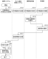
- FIG. 13 is a flowchart showing an example of a control procedure by the production management device.
- FIG. 13 is a schematic diagram showing an example of a display of options for a response that a worker can take;
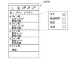
- FIG. 13 is a schematic diagram showing an example of work-related information guidance.
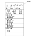
- FIG. 13 is a schematic diagram showing an example of a state after a worker has selected a task.
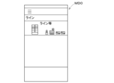
- 1 is a schematic diagram showing an example of guidance for the operating status of a production line and a substrate-related operating machine;
- FIG. 11 is a block diagram showing another example of the control block of the production management device.
- 10 is a flowchart showing another example of a control procedure by the production management device.
- FIG. 13
- Embodiment 1-1 Configuration Example of Production Line WL0
- the production management device 50 can be applied to at least one production line WL0 equipped with a substrate-related operation machine WM0.
- the production facility of the embodiment includes two production lines WL0, a first production line WL1 and a second production line WL2.
- a substrate-related work machine WM0 performs a predetermined substrate-related work on a substrate 90.
- the production line WL0 of the embodiment is equipped with multiple substrate-related work machines WM0, including a printer WM1, a print inspection machine WM2, a component mounting machine WM3, a reflow oven WM4, and a visual inspection machine WM5, and the substrate 90 is transported in the above order by a substrate transport device.
- the printer WM1 prints solder at the mounting positions of multiple components 91 on the board 90.
- the print inspection machine WM2 inspects the printing condition of the solder printed by the printer WM1.
- the component mounting machine WM3 mounts multiple components 91 on the board 90 on which the solder has been printed by the printer WM1.
- multiple components 91 can be mounted by sharing the load between the multiple component mounting machines WM3.
- the reflow furnace WM4 heats the board 90 on which multiple components 91 have been mounted by the component mounting machine WM3, melting the solder and performing soldering.
- the appearance inspection machine WM5 inspects the mounting state of the multiple components 91 mounted by the component mounting machine WM3.
- the production line WL0 can sequentially transport the boards 90 using multiple substrate-related work machines WM0 and produce the product boards 900 by performing production processes including inspection processes.
- the production line WL0 can also be equipped with substrate-related work machines WM0 such as functional inspection machines, buffer devices, substrate supply devices, substrate reversing devices, shield mounting devices, adhesive application devices, and ultraviolet ray irradiation devices as necessary.
- the multiple substrate-related operating machines WM0 and the line management device LC0 that make up the production line WL0 are communicatively connected by a communication unit.
- the line management device LC0 and the management device HC0 are communicatively connected by a communication unit.
- the communication unit only needs to be able to communicatively connect these devices by wire or wirelessly, and various communication methods can be used.
- a local area network is configured by the multiple substrate-related work machines WM0, the line management device LC0, and the management device HC0. Therefore, the multiple substrate-related work machines WM0 can communicate with each other via the communication unit. Also, the multiple substrate-related work machines WM0 can communicate with the line management device LC0 via the communication unit. Furthermore, the line management device LC0 and the management device HC0 can communicate with each other via the communication unit.
- the line management device LC0 controls the multiple substrate-related work machines WM0 that make up the production line WL0, and monitors the operating status of the production line WL0.
- the line management device LC0 stores various control data for controlling the multiple substrate-related work machines WM0.
- the line management device LC0 transmits control data to each of the multiple substrate-related work machines WM0.
- each of the multiple substrate-related work machines WM0 transmits its operating status and production status to the line management device LC0.
- the management device HC0 manages at least one (two in FIG. 1) line management device LC0. For example, the operating status and production status of the substrate-related operating machine WM0 acquired by the line management device LC0 are transmitted to the management device HC0 as necessary.
- the management device HC0 is communicatively connected to the production management system 80 by a wired or wireless communication unit 80a.
- the production management system 80 includes, for example, a maintenance database 81, a core system 82, a location management system 83, a material database 84, a layout management system 85, and a line integration management system 86.
- the maintenance database 81 stores maintenance information (e.g., maintenance timing, number of maintenance operations, etc.) for items used in the production of the product boards 900.
- the core system 82 is a higher-level management system that manages various information.
- the core system 82 can, for example, provide integrated management of the production plan for the product boards 900 using the substrate-related operation machine WM0, the progress of the production of the product boards 900, and the items used in the production of the product boards 900.
- the core system 82 is a known integrated management system, and can be provided in the user's system, for example.
- the location management system 83 manages the location information of the above items on the production floor.
- the location management system 83 manages, for example, the location information of the feeder 12a and the reel described below.
- the material database 84 stores information about the above items.
- the material database 84 stores, for example, part information, the manufacturers of the feeder 12a and the reel, etc. Information on the remaining number of parts, information on the electrical properties of the parts 91, etc. are included in the part information.
- the part information is stored in association with the identification information of the reel.
- the layout management system 85 stores the configuration of the production lines WL0 that produce the product boards 900, the configuration of the substrate-related work machines WM0 on each production line WL0, and the like.
- the line integration management system 86 works in conjunction with the above systems to notify the worker U0, manage remote operation by the worker U0, visualize the status of equipment including the substrate-related work machines WM0, and so on, thereby helping to ensure that production of the product boards 900 continues on the production line WL0.
- the component mounting machine WM3 mounts a plurality of components 91 on a board 90. As shown in Fig. 2, the component mounting machine WM3 includes a board transport device 11, a component supply device 12, a component transfer device 13, a component camera 14, a board camera 15, and a control device 16.
- the board transport device 11 is, for example, a belt conveyor, and transports the board 90 in the transport direction (X-axis direction).
- the board 90 is a circuit board on which electronic circuits, electric circuits, magnetic circuits, etc. are formed.
- the board transport device 11 transports the board 90 into the component mounting machine WM3 and positions the board 90 at a predetermined position within the machine. After the component mounting machine WM3 has completed the mounting process of multiple components 91, the board transport device 11 transports the board 90 out of the component mounting machine WM3.
- the component supply device 12 supplies a plurality of components 91 to be mounted on the board 90.
- the component supply device 12 has a plurality of feeders 12a arranged along the transport direction (X-axis direction) of the board 90.
- Each of the plurality of feeders 12a is equipped with a reel.
- a carrier tape containing a plurality of components 91 is wound around the reel.
- the feeder 12a feeds the carrier tape by a pitch to supply the components 91 so that they can be picked up at a supply position located at the tip side of the feeder 12a.
- the component supply device 12 can also supply electronic components (e.g., lead components) that are relatively large compared to chip components and the like, while they are arranged on a tray.
- the component transfer device 13 is equipped with a head drive device 13a and a movable table 13b.
- the head drive device 13a is configured to be able to move the movable table 13b in the X-axis direction and the Y-axis direction (directions perpendicular to the X-axis direction in a horizontal plane) using a linear motion mechanism.
- a mounting head 20 is detachably (replaceably) attached to the movable table 13b using a clamp member.
- the mounting head 20 uses at least one holding member 30 to pick up and hold a component 91 supplied by the component supply device 12, and mounts the component 91 on a board 90 positioned by the board transport device 11.
- the holding member 30 can be, for example, a suction nozzle, a chuck, etc.
- the component camera 14 and the board camera 15 may be publicly known imaging devices.
- the component camera 14 is fixed to the base of the component mounting machine WM3 so that its optical axis faces upward in the vertical direction (Z-axis direction perpendicular to the X-axis and Y-axis directions).
- the component camera 14 can image the component 91 held by the holding member 30 from below.
- the board camera 15 is mounted on the moving stage 13b of the component transfer device 13 so that its optical axis faces downward in the vertical direction (Z-axis direction).
- the board camera 15 can image the board 90 from above.
- the component camera 14 and the board camera 15 capture images based on control signals sent from the control device 16. Image data of the images captured by the component camera 14 and the board camera 15 are sent to the control device 16.
- the control device 16 is equipped with a known arithmetic device and storage device, and constitutes a control circuit. Information and image data output from various sensors provided in the component mounting machine WM3 are input to the control device 16. The control device 16 sends control signals to each device based on a control program and predetermined mounting conditions that have been set in advance.
- control device 16 causes the board camera 15 to capture an image of the board 90 positioned by the board transport device 11.
- the control device 16 processes the image captured by the board camera 15 to recognize the positioning state of the board 90.
- the control device 16 also causes the holding member 30 to pick up and hold the component 91 supplied by the component supply device 12, and causes the component camera 14 to capture an image of the component 91 held by the holding member 30.
- the control device 16 processes the image captured by the component camera 14 to recognize the holding posture of the component 91.
- the control device 16 moves the holding member 30 toward above the intended mounting position, which is set in advance by a control program or the like.
- the control device 16 also corrects the intended mounting position based on the positioning state of the board 90, the holding posture of the component 91, and the like, and sets the mounting position where the component 91 will actually be mounted.
- the intended mounting position and mounting position include a rotation angle in addition to the position (X-axis coordinate and Y-axis coordinate).
- the control device 16 corrects the target position (X-axis coordinates and Y-axis coordinates) and rotation angle of the holding member 30 to match the mounting position.
- the control device 16 lowers the holding member 30 at the corrected rotation angle in the corrected target position to mount the component 91 on the board 90.
- the control device 16 repeats the above pick-and-place cycle to execute the mounting process of mounting multiple components 91 on the board 90.
- the total time of the time required for a predetermined number of pick-and-place cycles and the time required to load and unload the board 90 corresponds to the cycle time for one board 90.
- Example configuration of production management device 50 For example, in component mounting machine WM3, when the type of product board 900 to be produced is changed, a changeover operation is performed. In addition, in component mounting machine WM3, when the components 91 that can be supplied from component supply device 12 are insufficient, a supply operation of components 91 is performed. The changeover operation and the supply operation are performed, for example, by worker U0, and feeder 12a and the like are replaced. What has been described above about component mounting machine WM3 can also be similarly applied to other substrate-related operation machine WM0. For example, in printing machine WM1, masks and the like are replaced by worker U0.
- the upper system when worker U0 is to perform a task, the upper system sends a task notification to worker U0.
- simply sending a task notification to worker U0 does not allow the upper system to grasp the status of worker U0.
- the upper system is unable to take action when it is necessary to address the task of worker U0, which may result in delays in the production of product boards 900 on production line WL0.
- the production equipment of the embodiment is provided with a production management device 50.
- the production management device 50 When considered as a control block, the production management device 50 is provided with a transmission unit 51 and a handling unit 52.
- the production management device 50 can also be provided with a guidance unit 53.
- the transmission unit 51, the handling unit 52, and the guidance unit 53 can be provided in various control devices.
- at least one of the transmission unit 51, the handling unit 52, and the guidance unit 53 can be provided in the line integrated management system 86.
- At least one of the transmission unit 51, the handling unit 52, and the guidance unit 53 can also be provided in the core system 82, etc. At least one of the transmission unit 51, the handling unit 52, and the guidance unit 53 can also be formed on the cloud. As shown in FIG. 3, in the production management device 50 of the embodiment, the transmission unit 51, the handling unit 52, and the guidance unit 53 are provided in the core system 82. Work notifications are sent from the core system 82 to the worker U0 via the line integrated management system 86 and the mobile terminal MD0.
- the mobile terminal MD0 is not limited as long as it is a communication device that can be carried by the worker U0.
- the production management device 50 of the embodiment executes control according to the flowchart shown in FIG. 4.
- the processes and decisions performed by the core system 82, the line integrated management system 86, the mobile terminal device MD0, and the worker U0 are divided by dashed straight lines.
- the transmission unit 51, the handling unit 52, and the guidance unit 53 are described with reference to the flowchart shown in FIG. 4.
- the matters described in this specification can be selected and applied as appropriate.
- the matters described in this specification can be combined as appropriate.
- the transmitting unit 51 transmits a work notification to the worker U0, which requires a reply to the work instruction.
- the work notification may take various forms as long as it notifies the worker U0 of the work instruction and requests the worker U0 to reply to the work instruction.
- the transmitting unit 51 may transmit the work notification to the worker U0 via the network shown in FIG.
- the transmitting unit 51 creates a work notification and transmits it to the line integrated management system 86 (step S11).
- the work notification includes information about the production line WL0 on which the worker U0 will be working, the substrate-related work machine WM0 (if the production line WL0 is equipped with multiple substrate-related work machines WM0 of the same type, it also includes the module number capable of identifying the substrate-related work machine WM0), and the like.
- the work notification also includes information about the work completion time when the worker U0 should complete the work, the work content, and the like.
- the work notification can be transmitted before the work completion time by an amount of time equal to the time required for the worker U0 to perform the work plus a predetermined slack time.
- the work notification can also be transmitted at any timing.
- the line integrated management system 86 sends a work notification to the portable terminal MD0 of the worker U0 who will be performing the work (step S12).
- the portable terminal MD0 displays the work notification (step S13).
- the worker U0 checks the work notification (step S14) and replies to the work instruction.
- the form of the reply is not limited and can take various forms.
- the worker U0 can reply using the portable terminal MD0 by text input, handwritten input, voice input, etc.
- the reply work of the worker U0 may become cumbersome.
- the processing on the side receiving the reply may become complicated.
- the transmitting unit 51 may therefore transmit a work notification that allows the worker U0 to select from a number of options as a response that he or she can take in response to the work instruction.
- the types and number of the multiple options are not limited, and may include various responses that the worker U0 can take.
- the multiple options may be two or more of an understood response, an impossible response, a delayed response, an unnecessary response, a replacement response, and an unknown response.
- the understanding response is a response in which worker U0 performs the work.
- the impossible response is a response in which worker U0 does not perform the work.
- the delay response is a response in which it takes time for worker U0 to start the work.
- the unnecessary response is a response in which worker U0 determines that the work is unnecessary.
- the substitution response is a response in which the work is handed over to another worker U0.
- the unknown response is a response in which the content of the work instructions is expressed as being unknown.
- FIG. 5 is an example of a display screen of the mobile terminal device MD0, showing an example of the display of options for the response that the worker can take.
- the understood response corresponds to "1. I will work on it.”
- the impossible response corresponds to "2. I cannot work on it.”
- the delayed response corresponds to "3. I will work on it later.”
- the unnecessary response corresponds to "4. No work is required.”
- the replacement response corresponds to "5. I will hand it over to worker B.”
- the unknown response corresponds to "6. I do not understand the instructions.”
- the mobile terminal MD0 displays reply options (step S15). Then, the worker U0 selects one option from the multiple options (step S16). In the example shown in FIG. 5, the worker U0 selects (tap) one option from the six options 1 to 6, and presses (tap) the confirmation button. This results in a reply to the work notification.
- the reply information sent from the mobile terminal MD0 is sent to the line integrated management system 86.
- the reply information is then sent from the line integrated management system 86 to the core system 82 (step S17). Note that when the worker U0 presses (taps) the cancel button on the display screen shown in FIG. 5, the screen returns from the reply selection screen to the normal screen.
- the handling unit 52 handles the work of the worker U0 as necessary based on the contents of the reply received from the worker U0.
- the handling unit 52 may take various forms as long as it can handle the work of the worker U0 as necessary. For example, if the worker U0 replies by handwriting input using the mobile terminal MD0, the handling unit 52 can convert the reply data into text using, for example, an optical character recognition device.
- the handling unit 52 can also perform voice recognition and convert the reply data into text.
- the handling unit 52 can learn the reply data replied by text input and the above-mentioned reply data converted into text, for example, by machine learning, and recognize the reply content received from the worker U0.
- the transmission unit 51 of the embodiment transmits a work notification that allows the worker U0 to select from a number of options which response he or she can take in response to the work instruction.
- the handling unit 52 can handle the response selected by the worker U0 as necessary. Specifically, the handling unit 52 determines whether or not the response selected by the worker U0 requires response (step S18). If response is required (Yes in step S18), the handling unit 52 takes action according to the contents of the reply (step S19). Then, the control ends temporarily. If response is not required (No in step S18), the control ends temporarily without carrying out the processing shown in step S19.
- the handling unit 52 does not need to handle that response. In contrast, if worker U0 selects another response, the handling unit 52 needs to handle the response selected by worker U0. Specifically, if the reply received from worker U0 is a replacement response, the handling unit 52 causes the sending unit 51 to send a work notification to the other worker U0 who will take over the work.
- the transmission unit 51 in this embodiment is provided in the core system 82.
- the core system 82 performs integrated management of the production plan for the product board 900 using the substrate-related operation machine WM0, the progress of the production of the product board 900, and the items used in the production of the product board 900.
- the core system 82 can also manage the work of the worker U0.
- the transmission unit 51 can easily grasp the work status of the worker U0 and can select the worker U0 who will take over the work based on the work status of the worker U0.
- the worker U0 who will take over the work is specified by the transmission unit 51 in the options for the response that the worker U0 can take. In the example shown in FIG. 5, worker B is specified. However, the worker U0 who receives the work notification can also specify another worker U0 who will take over the work.
- the sending unit 51 can send a work notification that allows the worker U0 to select the worker U0 who will take over the work from among the replacement response options.
- the reply includes information about the worker U0 who will take over the work.
- the handling unit 52 can recognize the worker U0 who will take over the work. Note that if there is no problem with the worker U0 designated by the worker U0 performing the work, the handling unit 52 can also approve the handover of the work. If there is a problem with the worker U0 designated by the worker U0 performing the work, the handling unit 52 can also cancel the handover of the work.
- the sending unit 51 can also send a work notification to the appropriate worker U0 at an appropriate time based on the work status of the worker U0. Therefore, as responses that the worker U0 can take, an impossible response, a delayed response, an unnecessary response, or an unknown response are not preferable. Therefore, when the response received from the worker U0 is an impossible response, a delayed response, an unnecessary response, or an unknown response, the handling unit 52 can request the manager A0 to instruct the worker U0.
- manager A0 is not limited to any person who can provide guidance and management for worker U0. For example, engineers, team leaders, etc. are included in manager A0.
- a request for guidance from worker U0 can be made by various methods.
- the handling unit 52 can use a mobile terminal MD0 carried by manager A0 to request guidance for worker U0 from manager A0.
- the handling unit 52 can adjust the work plan of worker U0 when the reply received from worker U0 indicates that the response is not possible, that a delayed response is required, or that a replacement response is required.
- the handling unit 52 assigns the task of worker U0 to another worker U0. In this case, the handling unit 52 causes the transmission unit 51 to send a task notification to the other worker U0 to whom the task has been assigned. Furthermore, if the reply received from worker U0 indicates that the task will be completed due to a delay, the handling unit 52 adjusts the task plan of worker U0 depending on the degree of the delay. For example, if the time required for worker U0 to start the task is within an acceptable range, the handling unit 52 changes the task completion time at which the task should be completed to match the required time.
- the handling unit 52 can also assign the work of worker U0 to another worker U0. In this case, the handling unit 52 causes the transmission unit 51 to send a work notification to the other worker U0 to whom the work has been assigned. In this way, the handling unit 52 can adjust the work plan of worker U0. Furthermore, the handling unit 52 can also adjust the work plan of worker U0 if the reply received from worker U0 is an unnecessary response or an unknown response. Furthermore, the handling unit 52 can also adjust the production plan for the product boards 900.
- the handling unit 52 should alert worker U0. Specifically, if the reply received from worker U0 is a delayed response, the handling unit 52 causes the transmission unit 51 to resend the work notification when a predetermined time has elapsed since the receipt of the delayed response. This reduces the likelihood of worker U0 forgetting to perform the work.
- the above-mentioned predetermined time (the timing for resending the work notification) can be set arbitrarily.
- the handling unit 52 obtains the relationship between the time elapsed since receiving the delayed response and the frequency of work forgetting through verification by the worker U0.
- the handling unit 52 can then set the elapsed time at which the frequency of work forgetting exceeds an acceptable range as the predetermined time (the timing for resending the work notification).
- the transmission unit 51 can also transmit a work notification that allows the worker U0 to select the time until the worker U0 starts the work in the delayed response option.
- the reply includes information regarding the time until the worker U0 starts the work. This allows the handling unit 52 to recognize the time until the worker U0 starts the work. Therefore, when the reply received from the worker U0 is a delayed response, the handling unit 52 can cause the transmission unit 51 to resend the work notification when the time has elapsed from receiving the delayed response to starting the work selected by the worker U0.
- worker U0 can select "3A. Work in 5 minutes” or "3B. Work in 20 minutes” as the delay response. For example, if worker U0 selects the former, handling unit 52 causes transmission unit 51 to resend the work notification 5 minutes after the delay response is received. If worker U0 selects the latter, handling unit 52 causes transmission unit 51 to resend the work notification 20 minutes after the delay response is received. This allows worker U0 to recognize the work at the time it should be started, reducing the chance of worker U0 forgetting to do the work. Note that the resending of the work notification can be repeated until worker U0 replies with an understanding response.
- the handling unit 52 can request the worker U0 to reply again about the reply received from the worker U0. For example, if the reply received from the worker U0 is a response to an unknown, the handling unit 52 can ask the worker U0 whether the work method related to the work instruction is unknown, or whether the location of the parts necessary for the work is unknown. The handling unit 52 can also teach a solution to anticipated unknown points. This is expected to encourage the worker U0 to reply with an understanding response, reducing the burden on the manager A0, for example. The worker U0 can also ask the handling unit 52 about unknown points, regardless of whether a work notification has been received or not.
- the guidance unit 53 provides the worker U0 with work-related information.
- the guidance unit 53 may take various forms as long as it can provide work-related information.
- the notification unit 53 notifies the mobile terminal MD0 carried by the worker U0 of the work-related information.
- the notification unit 53 also notifies the mobile terminal MD0 carried by the worker U0 of the work-related information when the work is to be completed by the worker U0 with a high priority and when the remaining time until the work completion time is short.
- the task-related information is provided to the worker U0 in the order of the tasks. This allows the worker U0 to obtain the task-related information necessary for the order of the tasks to be performed.
- the reply described above can be made while referring to the work-related information in the order of work.
- FIG. 6 is a display screen different from that of FIG. 5, showing an example of guidance for work-related information.
- the work performed by worker U0 is categorized into three categories, abnormal, warning, and information, in descending order of priority.
- Work categorized as abnormal is, for example, work to be done when an abnormality occurs in the substrate-related work machine WM0, and is shown in this figure with an icon of a circle with a cross.
- Work categorized as warning is, for example, work to be done when a problem occurs in the changeover area, and is shown in this figure with an icon of a triangle with an exclamation mark.
- Tasks classified as information are tasks that deal with problems that occur in the warehouse area, for example, and are represented in the diagram by an icon consisting of a circle with the Roman letter i (the initial letter of the English word "information"). The numbers in circles next to each icon indicate the number of tasks in question. Note that the more an task is classified as abnormal, the less time remaining until the task completion time, and the more urgent it is. The remaining time until the task completion time is long for tasks classified as abnormal, followed by tasks classified as warning, and then tasks classified as information.
- two tasks classified as abnormal are displayed in the upper section of the display screen.
- Two tasks classified as warning are displayed in the middle section of the display screen.
- One task classified as information is displayed in the lower section of the display screen.
- the work-related information is not limited to any particular information as long as it is related to the work of worker U0.
- the lines shown in the figure error codes, abnormality details, warning codes, warning details, and information are included in the work-related information.
- the “line, etc.” indicates information that can identify the production line WL0 on which the substrate-related operation machine WM0 is installed and the substrate-related operation machine WM0.
- the "error code” indicates information that can identify the type of abnormality.
- the "abnormality content” indicates the content of the abnormality.
- the "warning code” indicates information that can identify the type of warning.
- the “warning content” indicates the content of the warning.
- the “information” indicates the content of the work classified as information. When the worker U0 presses (tap) a specific work, the guidance unit 53 can display more detailed work-related information about the work.
- the guidance unit 53 can display work-related information such as the cause of the abnormality, countermeasures against the abnormality, a link (internet address) describing the countermeasures, the work process, the response time, and the slot number in which the target feeder 12a is installed.
- work-related information such as the cause of the abnormality, countermeasures against the abnormality, a link (internet address) describing the countermeasures, the work process, the response time, and the slot number in which the target feeder 12a is installed.
- the guidance unit 53 can also change the work-related information to be provided in response to a request from the worker U0.
- the guidance unit 53 can change the information to information on all work, information on only work classified as abnormal, information on only work classified as warning, or information on only work classified as information.
- the guidance unit 53 can change the information to information on all work, information according to the elapsed time, information according to the presence or absence of a reply, or information according to the presence or absence of a transfer.
- a transfer a form in which the worker U0 who receives a work notification designates the worker U0 who will take over the work.
- the guidance unit 53 can change to a display screen related to filters, replies, or forwarding.
- worker U0 can change the task-related information to be guided.
- the reply display screen is similar to the display screen shown in FIG. 5, and worker U0 can reply to the task notification.
- worker U0 can specify another worker U0 to take over the task.
- the worker U0 can select (tap) all, line, or system on the display screens shown in Figures 5 to 7.
- the guidance unit 53 can change the guidance to provide work-related information related to all production lines WL0 and substrate-related operation machines WM0, provide only work-related information related to a specific production line WL0 and substrate-related operation machine WM0, or provide only work-related information related to a specific control system.
- the work-related information includes the operating status of at least one of the production line WL0 on which the substrate-related work machine WM0 is installed and the substrate-related work machine WM0. For example, when the worker U0 selects (tap) an icon that visualizes the equipment status on the display screen that displays the detailed work-related information described above, the screen shown in FIG. 8 is displayed. On the display screen shown in the same figure, the guidance unit 53 provides guidance on the operating status of the production line WL0 on which the substrate-related work machine WM0 is installed and the substrate-related work machine WM0.
- the guidance unit 53 can provide information about the line, etc. (information that can identify the production line WL0, information that can identify the substrate-related operation machine WM0, etc.).
- the guidance unit 53 can also provide information about the substrate-related operation machine WM0 that has become a bottleneck, for example, by using an icon that resembles a cone-shaped ornament with a red body and a white line that is used at construction sites.
- the substrate-related operation machine WM0 that has become a bottleneck is the substrate-related operation machine WM0 that has the longest cycle time.
- the guidance unit 53 can also provide information about the connection status of the substrate-related operation machine WM0 (for example, whether it is started or not) by using an icon that resembles the substrate-related operation machine WM0.
- the guidance unit 53 can also provide information about the status of the boards 90 that have been carried into the substrate-related operation machine WM0 (for example, the number of boards 90, etc.).
- production management device 50 may also include a transmission unit 51 and a transfer unit 54. Also, production management device 50 may also include a guidance unit 53. Production management device 50 shown in the figure includes transmission unit 51, guidance unit 53, and transfer unit 54. Transmission unit 51, guidance unit 53, and transfer unit 54 may be provided in various control devices, communication devices, etc., and may also be formed on the cloud.
- the transmission unit 51 and the guidance unit 53 are provided in the core system 82, and the transfer unit 54 is provided in the mobile terminal MD0.
- the production management device 50 shown in FIG. 9 executes control according to the flowchart shown in FIG. 10. In this figure, the processes and decisions performed by the core system 82, the line integrated management system 86, the mobile terminal MD0, and the worker U0 are divided by dashed straight lines.
- the transmission unit 51 When issuing a work instruction to the worker U0 of the substrate-related operation machine WM0, the transmission unit 51 transmits a work notification to the worker U0. In the form shown in Figures 9 and 10, the work notification does not require a reply to the work instruction.
- the transmission unit 51 creates a work notification and transmits it to the line integrated management system 86 (step S21).
- the work notification can include information similar to that of the work notification already described.
- the line integrated management system 86 sends a work notification to the mobile terminal MD0 of the worker U0 who will be performing the work (step S22).
- the mobile terminal MD0 displays the work notification (step S23).
- the worker U0 checks the work notification (step S24) and determines whether or not to perform the work himself (step S25). If the worker U0 will perform the work himself (Yes in step S25), the worker U0 carries out the work (step S26). Then, control ends for the time being.
- step S25 If worker U0 is not performing the work himself (No in step S25), worker U0 presses (tap) the transfer button on the display screen of the mobile terminal MD0 (step S27). Then, worker U0 selects the transfer destination on the display screen of the mobile terminal MD0 (step S28).
- transfer refers to a form in which worker U0 who has received a work notification designates another worker U0 who will take over the work.
- Figure 11 is an example of the display screen of the mobile terminal MD0, showing an example of a display related to transfer.
- worker U0 selects (tap) the worker U0 who will take over the work from among the three workers U0, workers A to C, and presses (tap) the confirmation button (step S29). This designates the worker U0 who will take over the work, and a work notification is sent to the designated worker U0. Note that when worker U0 presses (tap) the cancel button in the display screen shown in FIG. 11, the screen returns from the transfer destination selection screen to the normal screen.
- the portable terminal MD0 determines whether the transfer process has been completed normally (step S30). If the transfer process has been completed normally (Yes in step S30), the portable terminal MD0 displays the completion of the transfer process (step S31). Then, control ends for the time being. If the transfer process has not been completed normally (No in step S30), the portable terminal MD0 displays a message indicating that the transfer process has not been completed normally (error display) and displays a suggestion for retransmission or other measures (step S32). Then, control ends for the time being.
- the production management method includes a transmission step and a handling step.
- the transmission step corresponds to the control performed by the transmission unit 51.
- the handling step corresponds to the control performed by the handling unit 52.
- the production management method may also include a guidance step.
- the guidance step corresponds to the control performed by the guidance unit 53.
- the production management method can also include a transmission process and a forwarding process.
- the transmission process corresponds to the control performed by the transmission unit 51.
- the forwarding process corresponds to the control performed by the forwarding unit 54.
- the production management method can also include a guidance process.
- the guidance process corresponds to the control performed by the guidance unit 53.
- 50 production management device
- 51 transmission unit
- 52 handling unit
- 53 guidance unit
- 82 Core system
- 90 Board
- 900 Product board
- U0 Worker
- A0 Manager
- WL0 Production line
- WM0 Board-related work machine.
Landscapes
- Engineering & Computer Science (AREA)
- Manufacturing & Machinery (AREA)
- Automation & Control Theory (AREA)
- General Engineering & Computer Science (AREA)
- Quality & Reliability (AREA)
- Physics & Mathematics (AREA)
- General Physics & Mathematics (AREA)
- Operations Research (AREA)
- Microelectronics & Electronic Packaging (AREA)
- General Factory Administration (AREA)
Abstract
Description
1-1.生産ラインWL0の構成例
生産管理装置50は、対基板作業機WM0を備える少なくとも一つの生産ラインWL0に適用することができる。図1に示すように、実施形態の生産設備は、第一生産ラインWL1および第二生産ラインWL2の二つの生産ラインWL0を備えている。
部品装着機WM3は、基板90に複数の部品91を装着する。図2に示すように、部品装着機WM3は、基板搬送装置11、部品供給装置12、部品移載装置13、部品カメラ14、基板カメラ15および制御装置16を備えている。
例えば、部品装着機WM3では、生産する製品基板900の種類が切り替わる場合に、段取り替え作業が行われる。また、部品装着機WM3では、部品供給装置12から供給可能な部品91が不足すると、部品91の補給作業が行われる。段取り替え作業および補給作業は、例えば、作業者U0によって行われ、フィーダ12aなどが交換される。部品装着機WM3について上述されていることは、他の対基板作業機WM0についても同様に言える。例えば、印刷機WM1では、作業者U0によってマスクなどが交換される。
送信部51は、対基板作業機WM0の作業者U0に作業指示を行う場合に、作業指示に対する返信が必要な作業通知を作業者U0に送信する。作業通知は、作業者U0に作業指示を通知し、作業指示に対して作業者U0の返信を要求するものであれば良く、種々の形態をとり得る。例えば、送信部51は、図1に示すネットワークを通じて、作業通知を作業者U0に送信することができる。
案内部53は、作業者U0に作業関連情報を案内する。案内部53は、作業関連情報を案内することができれば良く、種々の形態をとり得る。実施形態の案内部53は、作業者U0が携帯する携帯端末機MD0に作業関連情報を案内する。また、案内部53は、作業者U0が行う作業の優先度が高く、且つ、作業を完了すべき作業完了時刻までの残り時間が少ない作業から順に、作業者U0に作業関連情報を案内する。これにより、作業者U0は、実施すべき作業順に必要な作業関連情報を知得することができる。また、作業者U0は、実施すべき作業順に作業関連情報を参照しつつ、既述されている返信を行うことができる。
例えば、作業者U0が作業指示に対応できない場合、生産ラインWL0において、製品基板900の生産が停止する可能性がある。そこで、図9に示すように、生産管理装置50は、送信部51と、転送部54を備えることもできる。また、生産管理装置50は、案内部53を備えることもできる。同図に示す生産管理装置50は、送信部51と、案内部53と、転送部54とを備えている。送信部51、案内部53および転送部54は、種々の制御装置、通信機器などに設けることができ、クラウド上に形成することもできる。
生産管理装置50について既述されていることは、生産管理方法についても同様に言える。具体的には、生産管理方法は、送信工程と、対処工程とを備えている。送信工程は、送信部51が行う制御に相当する。対処工程は、対処部52が行う制御に相当する。生産管理方法は、案内工程を備えることもできる。案内工程は、案内部53が行う制御に相当する。
生産管理装置50によれば、作業者U0に作業指示を行う場合に、作業指示に対する返信が必要な作業通知を作業者U0に送信することができ、作業者U0から受信した返信内容に基づいて、作業者U0の作業について必要に応じて対処することができる。生産管理装置50について上述されていることは、生産管理方法についても同様に言える。
82:基幹システム、90:基板、900:製品基板、U0:作業者、
A0:管理者、WL0:生産ライン、WM0:対基板作業機。
Claims (12)
- 基板に所定の対基板作業を行う対基板作業機の作業者に作業指示を行う場合に、前記作業指示に対する返信が必要な作業通知を前記作業者に送信する送信部と、
前記作業者から受信した返信内容に基づいて、前記作業者の作業について必要に応じて対処する対処部と、
を備える生産管理装置。 - 前記送信部は、前記作業指示に対して前記作業者がとり得る対応を複数の選択肢の中から選択可能な前記作業通知を送信し、
前記対処部は、前記作業者によって選択された前記対応について、必要に応じて対処する請求項1に記載の生産管理装置。 - 前記複数の選択肢は、前記作業者が前記作業を行う了解対応、前記作業者が前記作業を行わない不可対応、前記作業者の前記作業の開始に時間を要する遅延対応、前記作業者が前記作業を不要と判断する不要対応、他の前記作業者に前記作業を引き継ぐ交代対応、および、前記作業指示の内容が不明であることを表明する不明対応のうちの二つ以上である請求項2に記載の生産管理装置。
- 前記対処部は、前記作業者から受信した前記返信内容が前記交代対応の場合に、前記作業を引き継ぐ他の前記作業者に対して、前記送信部に前記作業通知を送信させる請求項3に記載の生産管理装置。
- 前記対処部は、前記作業者から受信した前記返信内容が前記不可対応、前記遅延対応、前記不要対応または前記不明対応の場合に、管理者に対して前記作業者の指導を依頼する請求項3に記載の生産管理装置。
- 前記対処部は、前記作業者から受信した前記返信内容が前記不可対応、前記遅延対応または前記交代対応の場合に、前記作業者の作業計画を調整する請求項3に記載の生産管理装置。
- 前記対処部は、前記作業者から受信した前記返信内容が前記遅延対応の場合に、前記遅延対応の受信から所定時間が経過したタイミングで、前記送信部に前記作業通知を再送信させる請求項3に記載の生産管理装置。
- 前記作業者が行う前記作業の優先度が高く、且つ、前記作業を完了すべき作業完了時刻までの残り時間が少ない前記作業から順に、前記作業者に作業関連情報を案内する案内部を備える請求項1に記載の生産管理装置。
- 前記案内部は、前記作業者の要求に応じて案内する前記作業関連情報を変更する請求項8に記載の生産管理装置。
- 前記作業関連情報には、前記対基板作業機が設けられている生産ラインおよび前記対基板作業機のうちの少なくとも一つの稼働状況が含まれる請求項8または請求項9に記載の生産管理装置。
- 前記送信部は、前記対基板作業機を使用した製品基板の生産計画、前記製品基板の生産の進捗状況、および、前記製品基板の生産で使用される物品を統合管理する基幹システムに設けられる請求項1に記載の生産管理装置。
- 基板に所定の対基板作業を行う対基板作業機の作業者に作業指示を行う場合に、前記作業指示に対する返信が必要な作業通知を前記作業者に送信する送信工程と、
前記作業者から受信した返信内容に基づいて、前記作業者の作業について必要に応じて対処する対処工程と、
を備える生産管理方法。
Priority Applications (4)
| Application Number | Priority Date | Filing Date | Title |
|---|---|---|---|
| DE112023005853.9T DE112023005853T5 (de) | 2023-02-22 | 2023-02-22 | Produktionsverwaltungsvorrichtung und Produktionsverwaltungsverfahren |
| JP2025502010A JPWO2024176387A1 (ja) | 2023-02-22 | 2023-02-22 | |
| PCT/JP2023/006466 WO2024176387A1 (ja) | 2023-02-22 | 2023-02-22 | 生産管理装置および生産管理方法 |
| CN202380094216.6A CN120642591A (zh) | 2023-02-22 | 2023-02-22 | 生产管理装置及生产管理方法 |
Applications Claiming Priority (1)
| Application Number | Priority Date | Filing Date | Title |
|---|---|---|---|
| PCT/JP2023/006466 WO2024176387A1 (ja) | 2023-02-22 | 2023-02-22 | 生産管理装置および生産管理方法 |
Publications (1)
| Publication Number | Publication Date |
|---|---|
| WO2024176387A1 true WO2024176387A1 (ja) | 2024-08-29 |
Family
ID=92500398
Family Applications (1)
| Application Number | Title | Priority Date | Filing Date |
|---|---|---|---|
| PCT/JP2023/006466 Ceased WO2024176387A1 (ja) | 2023-02-22 | 2023-02-22 | 生産管理装置および生産管理方法 |
Country Status (4)
| Country | Link |
|---|---|
| JP (1) | JPWO2024176387A1 (ja) |
| CN (1) | CN120642591A (ja) |
| DE (1) | DE112023005853T5 (ja) |
| WO (1) | WO2024176387A1 (ja) |
Citations (3)
| Publication number | Priority date | Publication date | Assignee | Title |
|---|---|---|---|---|
| JP2000214905A (ja) * | 1999-01-25 | 2000-08-04 | Mitsubishi Electric Corp | 作業管理支援装置 |
| JP2002149747A (ja) * | 2000-11-10 | 2002-05-24 | Aqura Home Co Ltd | 電子的な工程表を用いた工程管理方法 |
| WO2022097360A1 (ja) * | 2020-11-09 | 2022-05-12 | パナソニックIpマネジメント株式会社 | 搬送作業システム、作業管理装置、搬送ロボット制御装置、および搬送作業システムの制御方法 |
-
2023
- 2023-02-22 WO PCT/JP2023/006466 patent/WO2024176387A1/ja not_active Ceased
- 2023-02-22 JP JP2025502010A patent/JPWO2024176387A1/ja active Pending
- 2023-02-22 DE DE112023005853.9T patent/DE112023005853T5/de active Pending
- 2023-02-22 CN CN202380094216.6A patent/CN120642591A/zh active Pending
Patent Citations (3)
| Publication number | Priority date | Publication date | Assignee | Title |
|---|---|---|---|---|
| JP2000214905A (ja) * | 1999-01-25 | 2000-08-04 | Mitsubishi Electric Corp | 作業管理支援装置 |
| JP2002149747A (ja) * | 2000-11-10 | 2002-05-24 | Aqura Home Co Ltd | 電子的な工程表を用いた工程管理方法 |
| WO2022097360A1 (ja) * | 2020-11-09 | 2022-05-12 | パナソニックIpマネジメント株式会社 | 搬送作業システム、作業管理装置、搬送ロボット制御装置、および搬送作業システムの制御方法 |
Also Published As
| Publication number | Publication date |
|---|---|
| DE112023005853T5 (de) | 2025-12-11 |
| JPWO2024176387A1 (ja) | 2024-08-29 |
| CN120642591A (zh) | 2025-09-12 |
Similar Documents
| Publication | Publication Date | Title |
|---|---|---|
| CN110168458B (zh) | 管理装置、安装关联装置及安装系统 | |
| US8849442B2 (en) | Component mounting line and component mounting method | |
| JP6622801B2 (ja) | 案内装置及び案内システム | |
| WO2015079560A1 (ja) | 対回路基板作業システムのデータ更新方法及び対回路基板作業システム | |
| JP2012129449A (ja) | 部品実装装置および部品実装装置における機種切替え方法 | |
| CN113647208A (zh) | 生产数据制成装置以及生产数据制成方法 | |
| JP2022160528A (ja) | 生産計画作成方法および生産計画作成装置並びに生産計画作成プログラム | |
| JP2018055342A (ja) | 管理システムおよび管理方法 | |
| JPWO2015029244A1 (ja) | 基板作業機が用いるデータの処理装置とそれを有する基板作業システム | |
| JPWO2018020556A1 (ja) | 基板生産管理装置および基板生産管理方法 | |
| EP4071567B1 (en) | Operation state display device and operation state display method | |
| JP2018124848A (ja) | 生産管理装置および生産状況表示方法 | |
| CN120642591A (zh) | 生产管理装置及生产管理方法 | |
| JP7065294B2 (ja) | 製造システムおよび製造方法 | |
| JP2023008625A (ja) | 作業者支援システムおよび作業者支援方法 | |
| US20260057756A1 (en) | Work machine guidance device and work machine guidance method | |
| US20260044794A1 (en) | Remote operation notification system and remote operation notification method | |
| CN117356176A (zh) | 作业装置 | |
| JP2022053087A (ja) | 検査支援装置および検査支援方法 | |
| JP7573714B2 (ja) | 管理装置、実装システム及びエラー対処方法 | |
| JP7261935B2 (ja) | データ管理装置およびデータ管理方法 | |
| WO2025134177A1 (ja) | 作業支援装置および作業支援方法 | |
| WO2026042164A1 (ja) | 生産管理装置 | |
| WO2025187042A1 (ja) | 案内装置および案内方法 | |
| JP2018142186A (ja) | 作業指示システムおよび作業指示方法 |
Legal Events
| Date | Code | Title | Description |
|---|---|---|---|
| 121 | Ep: the epo has been informed by wipo that ep was designated in this application |
Ref document number: 23924041 Country of ref document: EP Kind code of ref document: A1 |
|
| WWE | Wipo information: entry into national phase |
Ref document number: 2025502010 Country of ref document: JP |
|
| WWE | Wipo information: entry into national phase |
Ref document number: 202380094216.6 Country of ref document: CN |
|
| WWP | Wipo information: published in national office |
Ref document number: 202380094216.6 Country of ref document: CN |
|
| WWE | Wipo information: entry into national phase |
Ref document number: 112023005853 Country of ref document: DE |
|
| WWP | Wipo information: published in national office |
Ref document number: 112023005853 Country of ref document: DE |
|
| 122 | Ep: pct application non-entry in european phase |
Ref document number: 23924041 Country of ref document: EP Kind code of ref document: A1 |