WO2024176308A1 - 摺動部材、及び、転がり軸受 - Google Patents
摺動部材、及び、転がり軸受 Download PDFInfo
- Publication number
- WO2024176308A1 WO2024176308A1 PCT/JP2023/006019 JP2023006019W WO2024176308A1 WO 2024176308 A1 WO2024176308 A1 WO 2024176308A1 JP 2023006019 W JP2023006019 W JP 2023006019W WO 2024176308 A1 WO2024176308 A1 WO 2024176308A1
- Authority
- WO
- WIPO (PCT)
- Prior art keywords
- sheet
- metal ring
- ring
- disposed
- rubber
- Prior art date
- Legal status (The legal status is an assumption and is not a legal conclusion. Google has not performed a legal analysis and makes no representation as to the accuracy of the status listed.)
- Ceased
Links
Images






Classifications
-
- F—MECHANICAL ENGINEERING; LIGHTING; HEATING; WEAPONS; BLASTING
- F16—ENGINEERING ELEMENTS AND UNITS; GENERAL MEASURES FOR PRODUCING AND MAINTAINING EFFECTIVE FUNCTIONING OF MACHINES OR INSTALLATIONS; THERMAL INSULATION IN GENERAL
- F16C—SHAFTS; FLEXIBLE SHAFTS; ELEMENTS OR CRANKSHAFT MECHANISMS; ROTARY BODIES OTHER THAN GEARING ELEMENTS; BEARINGS
- F16C33/00—Parts of bearings; Special methods for making bearings or parts thereof
- F16C33/72—Sealings
- F16C33/76—Sealings of ball or roller bearings
Definitions
- This disclosure relates to sliding members and rolling bearings.
- Patent Document 1 A rolling bearing with an anti-electrolytic corrosion function is disclosed in Patent Document 1.
- the rolling bearing described in Patent Document 1 is a bearing that supports the rotating shaft of an electric motor mounted on an electric vehicle or the like.
- This rolling bearing comprises an outer ring, an inner ring, a number of balls arranged between the outer ring and the inner ring, and an annular seal (sliding member) that closes the end opening of the bearing internal space between the outer ring and the inner ring.
- the seal comprises conductive rubber.
- the inner and outer peripheries of this rubber are in contact with the inner ring and the outer ring, respectively.
- the rubber contacting the inner ring and the outer ring electrically connects the inner ring to the outer ring through the rubber.
- the rubber contacting the inner ring and the outer ring prevents current from flowing between the inner ring and the balls and between the outer ring and the balls, thereby preventing electrolytic corrosion of the inner ring raceway, the outer ring raceway, and the
- the rubber of the seal (sliding member) in Patent Document 1 has a certain degree of conductivity due to the carbon fibers kneaded into it.
- the present disclosure aims to increase the conductivity of the sliding member.
- the slide member of the present disclosure comprises: A metal ring; A sheet which is a nonwoven or woven fabric formed of conductive fibers; A rubber;
- the sheet is a fixing portion that is fixed in contact with a first member made of a steel material on a first side in a radial direction of the metal ring; a sliding portion that is in slidable contact with a second member made of a steel material on a second radial side of the metal ring; and an intermediate portion located between the fixed portion and the sliding portion
- the metal ring has a first surface disposed on a first axial side or on the first axial side and a first radial side, and a second surface disposed on a second axial side or on the second axial side and a second radial side, the intermediate portion is disposed on the first surface;
- the fixing portion is disposed on a first side in a radial direction relative to an end portion on a first side in a radial direction of the metal ring, the sliding portion is
- the rolling bearing of the present disclosure comprises: an inner ring having an inner ring raceway; an outer ring having an outer ring raceway disposed radially outward of the inner ring raceway; a plurality of rolling elements rollably disposed between the inner ring raceway and the outer ring raceway;
- the above-mentioned sliding member, one of the inner ring and the outer ring is the first member, The other of the inner ring and the outer ring is the second member.
- the sliding member of the present disclosure includes a nonwoven or woven sheet formed from conductive fibers.
- the sheet has a lower electrical resistance than rubber containing carbon fibers kneaded into it, and can electrically connect a first member and a second member.
- the sliding member of the present disclosure can pass an electric current from one of the first member and the second member to the other via the sheet.
- the sliding member of the present disclosure can firmly bond the first portion of the rubber, the sheet, and the metal ring by the second and third portions of the rubber.
- FIG. 1 is a cross-sectional view showing an example of a rolling bearing according to the present disclosure.
- FIG. 2 is a side view of the sliding member as viewed from a second axial side.
- FIG. 3 is a cross-sectional view taken along line AA of FIG.
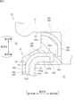
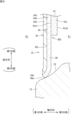
- FIG. 4 is a cross-sectional view taken along line BB of FIG. 5 is an enlarged cross-sectional view of a radially outer portion of the sliding member shown in FIG. 3.
- FIG. 6 is an enlarged cross-sectional view of a radially inner portion of the sliding member shown in FIG. 3.
- FIG. 7 is an enlarged cross-sectional view of a radially outer portion of the sliding member shown in FIG.
- FIG. 8 is an enlarged cross-sectional view of a radially inner portion of the sliding member shown in FIG.
- FIG. 9 is a cross-sectional view showing a part of a molding die for the sliding member.
- FIG. 10 is a cross-sectional view showing a part of a molding die for a sliding member.
- FIG. 11 is an enlarged photograph showing the radially inner end portion of the sliding member.
- the slide member of the present disclosure is A metal ring; A sheet which is a nonwoven or woven fabric formed of conductive fibers; A rubber;
- the sheet is a fixing portion that is fixed in contact with a first member made of a steel material on a first side in a radial direction of the metal ring; a sliding portion that is in slidable contact with a second member made of a steel material on a second radial side of the metal ring; and an intermediate portion located between the fixed portion and the sliding portion
- the metal ring has a first surface disposed on a first axial side or on the first axial side and a first radial side, and a second surface disposed on a second axial side or on the second axial side and a second radial side, the intermediate portion is disposed on the first surface;
- the fixing portion is disposed on a first side in a radial direction relative to an end portion on a first side in a radial direction of the metal ring, the sliding portion is disposed
- the sliding member includes a sheet that is a nonwoven or woven fabric formed from conductive fibers, the sheet being a member with lower electrical resistance than rubber in which carbon fibers are kneaded, and the sliding member can electrically connect the first member and the second member.
- the sliding member can pass an electric current from one of the first member and the second member to the other via the sheet.
- the sliding member can firmly bond the first part of the rubber, the sheet, and the metal ring by the second and third parts of the rubber.
- the sheet has holes through which the second portion and the third portion each penetrate.
- the sliding member can have the second and third portions disposed on the second surface of the metal ring through the holes in the sheet from the first portion of the rubber.
- the rolling bearing of the present disclosure has an inner ring having an inner ring raceway; an outer ring having an outer ring raceway disposed radially outward of the inner ring raceway; a plurality of rolling elements rollably disposed between the inner ring raceway and the outer ring raceway;
- the rolling bearing can electrically connect the outer ring and inner ring with a sheet, and current can be passed from one of the outer ring and inner ring to the other via this sheet, suppressing electrical corrosion of the outer ring raceway and inner ring raceway.
- FIG. 1 is a cross-sectional view showing an example of a rolling bearing according to the present disclosure.
- a rolling bearing 10 shown in Fig. 1 supports a rotating shaft S of a motor mounted in, for example, an electric vehicle or a hybrid vehicle.
- the rotating shaft S is indicated by a virtual line (two-dot chain line).
- the rolling bearing 10 includes an outer ring 11, an inner ring 12, a plurality of rolling elements 13, a cage 14, and a sliding member 15.
- the rolling elements 13 are balls.
- the rolling bearing 10 is a deep groove ball bearing.
- the outer ring 11 is attached to a housing H of a motor.
- the inner ring 12 is fitted to and fixed on the outer circumferential surface of a rotating shaft S.
- the housing H is shown by a virtual line (two-dot chain line).
- the outer ring 11 is a fixed ring
- the inner ring 12 is a rotating ring.
- the outer ring 11 and the inner ring 12 are formed of a steel material such as bearing steel.
- the bearing steel may be high carbon chromium bearing steel (for example, SUJ2 or SUJ3 as specified by the JIS standard).
- the outer ring 11 and the inner ring 12 may be other steel materials such as carburized bearing steel, carbon steel, chromium steel, and stainless steel.
- the outer ring 11 and the inner ring 12 are arranged concentrically.
- the central axis of the outer ring 11 and the inner ring 12 coincides with the central axis C of the rolling bearing 10.
- the direction along the central axis C and the direction parallel to the central axis C are defined as the "axial direction”.
- the direction perpendicular to the central axis C is defined as the "radial direction”.
- the direction along the circle centered on the central axis C is defined as the "circumferential direction”.
- the left side of FIG. 1 is the axial first side
- the right side of FIG. 1 is the axial second side.
- one of the radial outer side and the radial inner side may be referred to as the radial first side, and the other may be referred to as the radial second side.
- the radial outer side is the radial first side
- the radial inner side is the radial second side.
- the outer ring raceway 21 is provided on the inner peripheral surface of the outer ring 11.
- the balls 13 roll on this outer ring raceway 21.
- Two shoulders 22 are provided on both axial sides of the outer ring raceway 21.
- Two annular grooves 23 are provided between the shoulders 22 and the side surfaces of the outer ring 11.
- the annular grooves 23 have a circumferentially continuous annular groove shape.
- the sliding member 15 is attached to the annular groove 23 arranged on the first axial side of the outer ring 11.
- the sliding member 15 is not attached to the annular groove 23 arranged on the second axial side of the outer ring 11.
- the sliding member 15 may be attached to the annular groove 23 arranged on the second axial side of the outer ring 11. If the sliding member 15 is not attached to the annular groove 23, the annular groove 23 arranged on the second axial side of the outer ring 11 may be omitted.
- the inner ring raceway 31 is provided on the outer peripheral surface of the inner ring 12.
- the balls 13 roll on this inner ring raceway 31.
- Two shoulders 32 are provided on both axial sides of the inner ring raceway 31.
- Two sliding member contact surfaces 33 are provided between the shoulders 32 and the side surfaces of the inner ring 12.
- the sliding member contact surface 33 is provided in an annular shape around the entire circumference of the inner ring 12.
- the sliding member contact surface 33 is groove-shaped in a cross section including the central axis of the inner ring 12.
- the radial inner end of the sliding member 15 is in contact with the sliding member contact surface 33.
- the balls 13 are arranged between the outer ring 11 and the inner ring 12.
- the balls 13 roll and contact the outer ring raceway 21 and the inner ring raceway 31.
- the multiple balls 13 are held at intervals in the circumferential direction by the annular cage 14.
- the cage 14 has an annular body 16 and a number of horns (pillars) 17.
- the annular body 16 is provided on the second axial side of the balls 13.
- the multiple horns (pillars) 17 are provided extending from the annular body 16 to the first axial side.
- the pocket 18 is a space between two circumferentially adjacent horns 17 on the first axial side of the annular body 16.
- the pocket 18 accommodates the balls 13.
- the pocket 18 is open on the first axial side.
- the sliding member 15 is formed in an annular shape.
- the sliding member 15 is fixed to the outer ring (first member) 11 and slides against the inner ring (second member) 12. Specifically, the sliding member 15 is fixed to the outer ring 11 by fitting its radial outer end (end on the first radial side) into the annular groove 23 on the first axial side of the outer ring 11. The radial inner end (end on the second radial side) of the sliding member 15 contacts the sliding member contact surface 33 of the inner ring 12.
- the sliding member 15 is provided only on the first axial side of the rolling bearing 10, and is not provided on the second axial side of the rolling bearing 10.
- the bearing internal space K1 which is an annular space between the outer ring 11 and the inner ring 12 and in which the balls 13 are present, opens to the second axial side.
- the sliding member 15 divides the bearing internal space K1, in which the balls 13 exist, from the bearing external space K2, which is the space on the first axial side of the rolling bearing 10.
- the sliding member 15 is conductive between its radially outer end and its radially inner end.
- the sliding member 15 includes a conductive sheet 43, and a fixed portion 45 of the sheet 43 is exposed on the surface at the radially outer end of the sliding member 15, and a sliding portion 46 of the sheet 43 is exposed on the surface at the radially inner end of the sliding member 15. Therefore, the sliding member 15 forms a current path for preventing current generated by a motor or the like from flowing between the outer ring 11 and the inner ring 12 via the rolling elements 13.
- An oil film made of lubricating oil or grease is formed between the balls 13 and the inner ring raceway 31, and between the balls 13 and the outer ring raceway 21.
- the oil film has insulating properties. Due to the insulating properties of the oil film, the balls 13 and the inner ring raceway 31, and the balls 13 and the outer ring raceway 21 are insulated from each other. When an oil film is formed between the balls 13 and the inner ring raceway 31 and a potential difference of a predetermined value or less occurs between the balls 13 and the inner ring raceway 31, no current flows between the inner ring raceway 31 and the balls 13.
- Fig. 2 is a side view of the sliding member as viewed from a second axial side.
- Fig. 3 is a cross-sectional view taken along line A-A in Fig. 2.
- Fig. 4 is a cross-sectional view taken along line B-B in Fig. 2.
- Fig. 5 is an enlarged cross-sectional view of a radially outer portion of the sliding member shown in Fig. 3.
- Fig. 6 is an enlarged cross-sectional view of a radially inner portion of the sliding member shown in Fig. 3.
- Fig. 7 is an enlarged cross-sectional view of a radially outer portion of the sliding member shown in Fig. 4.
- Fig. 8 is an enlarged cross-sectional view of a radially inner portion of the sliding member shown in Fig. 4.
- the sliding member 15 has a metal ring 41, rubber 42, and a sheet 43.
- the metal ring 41, rubber 42, and sheet 43 are all annular.
- the metal ring 41, rubber 42, and sheet 43 are bonded together to form a single unit.
- the metal ring 41 is made of metal such as galvanized steel or stainless steel.
- the metal ring 41 is formed by processing a plate material.
- the metal ring 41 includes an annular portion 41a formed in an annular shape and a cylindrical portion 41b formed in a cylindrical shape.
- the annular portion 41a is arranged perpendicular to the axial direction.
- the cylindrical portion 41b is arranged parallel to the axial direction.
- the cylindrical portion 41b is arranged at the radial outer end of the annular portion 41a.
- the cylindrical portion 41b extends from the radial outer end of the annular portion 41a to the second axial side (the bearing internal space K1 side).
- the annular portion 41a and the cylindrical portion 41b of the metal ring 41 are formed by plastic processing the plate material into a substantially L-shape.
- the side surface 41a1 on the first axial side of the annular portion 41a of the metal ring 41 and the peripheral surface 41b1 on the radially outer side (first radial side) of the cylindrical portion 41b are referred to as the "first surface 41a1, 41b1".
- the side surface 41a2 on the second axial side of the annular portion 41a of the metal ring 41 and the peripheral surface 41b2 on the radially inner side (second radial side) of the cylindrical portion 41b are referred to as the "second surface 41a2, 41b2". Therefore, the first surface 41a1, 41b1 and the second surface 41a2, 41b2 face in opposite directions to each other in the axial and radial directions.
- the rubber 42 is conductive.
- the rubber 42 is manufactured, for example, by blending a conductive material with synthetic rubber.
- the conductive material is carbon black, metal powder, etc. The specific structure of the rubber 42 will be described later, along with the structure of the sheet 43.
- the sheet 43 is made of a nonwoven or woven fabric made of conductive fibers.
- the sheet 43 uses carbon fibers as the conductive fibers.
- the conductive fibers may be made of other materials, such as fibers made of conductive metals such as copper and nickel.
- the electrical resistance of the sheet 43 is lower than the electrical resistance of the rubber 42.
- the sheet 43 further contains a synthetic resin as a binder.
- the binder is fixed to the surface of a portion of the conductive fibers contained in the sheet 43.
- the sheet 43 in this embodiment is a nonwoven fabric or woven fabric made of conductive fibers with the binder fixed thereto.
- the sliding member 15 can use, for example, DonaCarbo (registered trademark) paper manufactured by Osaka Gas Chemicals Co., Ltd. as the sheet 43.
- the sheet 43 has an intermediate portion 44, a fixed portion 45, and a sliding portion 46 integrally.
- the intermediate portion 44 is a portion that is mainly adhered to the metal ring 41.
- the binder fixed to the surface of the conductive fiber contained in the sheet 43 and the metal ring 41 are easily adhered by adhesive.
- the intermediate portion 44 has a first portion 44a and a second portion 44b.
- the first portion 44a extends in the radial direction.
- the first portion 44a is adhered to the side surface 41a1 (first surface) on the axial first side (bearing external space K2 side) of the annular portion 41a of the metal ring 41.
- the second portion 44b of the sheet 43 is adhered to the outer peripheral surface 41b1 (first surface) of the cylindrical portion 41b of the metal ring 41.
- the shape of the intermediate portion 44 of the sheet 43 is maintained mainly by the metal ring 41 and the rubber 42.
- the fixed portion 45 of the seat 43 is formed at least partially continuous with the second portion 44b, which is the intermediate portion 44. As shown in Figs. 5 and 7, the fixed portion 45 has a third portion 45a and a fourth portion 45b.
- the third portion 45a curves from the end of the second portion 44b of the intermediate portion 44 on the second axial side (the bearing internal space K1 side) and extends further radially outward.
- the fourth portion 45b curves from the radial outer end of the third portion 45a toward the first axial side.
- the tip of the fourth portion 45b constitutes the radial outer end of the seat 43.
- the tips of the third portion 45a and the fourth portion 45b are in direct contact with the annular groove 23 of the outer ring 11.
- the sliding portion 46 of the seat 43 is formed at least partially continuous with the radially inner side of the first portion 44a, which is the intermediate portion 44.
- the sliding portion 46 has a fifth portion 46a at its radially inner end, which is in direct contact with the sliding member contact surface 33 of the inner ring 12.
- the rubber 42 is bonded to the sheet 43.
- the rubber 42 has first portions 42a, 42b, and 42c that are provided on substantially the entire side surface of the sheet 43 on the first axial side. As shown in Figures 5 and 7, a portion 42a of the first portion of the rubber 42 is provided in an area surrounded by the second portion 44b, the third portion 45a, and the fourth portion 45b of the sheet 43.
- the other part 42b of the first part of the rubber 42 is provided with a substantially constant thickness along the side surface of the first axial direction side of the first part 44a of the intermediate part 44 of the sheet 43, as shown in Figures 5 to 8.
- the other part 42c of the first part of the rubber 42 is provided with a substantially constant thickness along the side surface of the first axial direction side of the sliding part 46 of the sheet 43.
- the rubber 42 further has a second portion 42d and a third portion 42e.
- the second portions 42d and the third portions 42e are each provided in a plurality of portions at intervals in the circumferential direction.
- the rubber 42 has four second portions 42d and four third portions 42e.
- the four second portions 42d and the four third portions 42e are arranged in the same phase in the circumferential direction.
- the second portion 42d of the rubber 42 is disposed on the second surface 41b2 of the metal ring 41 beyond the first portion 42a of the rubber 42, beyond the radially outer end of the metal ring 41 (the end of the cylindrical portion 41b on the second axial side). More specifically, the second portion 42d is provided so as to cover the end face on the second axial side of the cylindrical portion 41b of the metal ring 41 and the inner peripheral surface 41b2 of the cylindrical portion 41b. The second portion 42d passes through the hole 43a formed in the sheet 43 from the first portion 42a and reaches the second surface 41b2 of the metal ring 41.
- the third portion 42e of the rubber 42 is disposed on the second surface 41a2 of the metal ring 41, extending from the first portions 42b and 42c of the rubber 42 beyond the radially inner end of the annular portion 41a of the metal ring 41. More specifically, the third portion 42e covers the end face on the second radial side of the annular portion 41a and the side surface 41a2 on the second axial side. The third portion 42e is bonded to the side surface 41a2 of the annular portion 41a. The third portion 42e extends from the first portions 42b and 42c through a hole 43b formed in the sheet 43 to the second surface 41a2 of the metal ring 41.
- the second portion 42d and the third portion 42e of the rubber 42 firmly bond the first portions 42a, 42b, and 42c of the rubber 42 to the sheet 43 and the metal ring 41. Therefore, the second portion 42d and the third portion 42e of the rubber 42 prevent the sheet 43 from peeling off from the metal ring 41, and prevent the rubber 42 from peeling off from the sheet 43.
- the shape of the sheet 43 is maintained not only by the metal ring 41 but also by the rubber 42.
- a portion 42a of the first portion of the rubber 42 elastically supports the fourth portion 45b of the sheet 43 from the radially inner side.
- the cylindrical portion 41b of the metal ring 41 supports the portion 42a of the rubber 42 from the radially inner side. Therefore, the fixed portion (radial outer end portion) 45 of the sheet 43 is pressed against the annular groove 23 of the outer ring 11 by the elasticity of the portion 42a of the rubber 42 supported by the cylindrical portion 41b of the metal ring 41, and is securely brought into contact with the annular groove 23.
- the sheet 43 includes a nonwoven fabric or a woven fabric formed of conductive fibers.
- the sheet 43 contains voids inside in the material state before the sliding member 15 is manufactured.
- the rubber 42 also exists in the voids of the sheet 43.
- the sliding member 15 is manufactured by inserting the metal ring 41 and the sheet 43 into a mold, vulcanizing the rubber material constituting the rubber 42 while molding it into a predetermined shape, and bonding the rubber material to the metal ring 41 and the sheet 43.
- this manufacturing process is also referred to as "vulcanization adhesion".
- the rubber 42 enters the voids in the sheet 43.
- the rubber 42 is easily bonded to the binder.
- At least a portion of the fixed portion 45 of the seat 43 contacts the annular groove 23 of the outer ring 11.
- at least a portion of the sliding portion 46 of the seat 43 contacts the sliding member contact surface 33 of the inner ring 12.
- the second portions 42d of the rubber 42 are spaced apart in the circumferential direction. Therefore, the intermediate portion 44 and the fixed portion 45 of the sheet 43 are continuous between the second portions 42d adjacent in the circumferential direction.
- This continuous portion is indicated by the reference symbol 43c and is called the first continuous portion 43c.
- the first continuous portion 43c is provided in four locations spaced apart in the circumferential direction.
- the third portions 42e of the rubber 42 are spaced apart in the circumferential direction. Therefore, between the third portions 42e adjacent in the circumferential direction, the middle portion 44 and the sliding portion 46 of the sheet 43 are continuous.
- This continuous portion is indicated by the reference symbol 43d and is called the second continuous portion 43d.
- the second continuous portion 43d is provided in four locations spaced apart in the circumferential direction.
- the first continuous portion 43c and the second continuous portion 43d are arranged in the same phase in the circumferential direction. In other words, the first continuous portion 43c and the second continuous portion 43d are located on a common radial line passing through the central axis C.
- each second portion 42d is greater than the circumferential length of each first continuous portion 43c.
- the circumferential length of each third portion 42e is greater than the circumferential length of each second continuous portion 43d. Therefore, the rubber 42, the sheet 43, and the metal ring 41 are firmly bonded over a wide circumferential range by the second portion 42d and the third portion 42e.
- the sheet 43 includes a nonwoven fabric or a woven fabric in which a plurality of conductive fibers are in contact with each other.
- the conductive fibers in contact with each other are electrically conductive.
- the fixed portion 45, the intermediate portion 44, and the sliding portion 46 of the sheet 43 are radially continuous via the first and second continuous portions 43c and 43d. Therefore, the sheet 43 is conductive throughout the entire radial direction from the fixed portion 45 to the sliding portion 46 due to the contact between the conductive fibers. Since the sheet 43 is in contact with the outer ring 11 and the inner ring 12, the outer ring 11 and the inner ring 12 are electrically connected via the sheet 43.
- the metal ring 41 and the rubber 42, which are conductive are in contact with the sheet 43.
- the outer ring 11 and the inner ring 12 are electrically connected via the metal ring 41 and the rubber 42, which are conductive, in addition to the sheet 43.
- the sliding member 15 of this embodiment can dissipate electric charge from one of the fixed portion 45 and the sliding portion 46 to the other.
- the sliding member 15 of this embodiment can also dissipate electric charge from one of the member fixed to the fixed portion 45 and the member sliding on the sliding portion 46 to the other.
- the rolling bearing 10 of this embodiment can dissipate electric charge from one of the outer ring 11 and the inner ring 12 to the other of the outer ring 11 and the inner ring 12 via the sliding member 15, making it possible to suppress electrolytic corrosion of the balls 13 and the outer ring raceway 21 and the inner ring raceway 31 on which the balls 13 roll.
- the first continuous portion 43c and the second continuous portion 43d which serve as the path of electric charge, are arranged in the same phase in the circumferential direction, so the distance between them is the shortest. This makes it possible to further increase the conductivity between the fixed portion 45 and the sliding portion 46.
- each second portion 42d and the circumferential length of each first continuous portion 43c can be changed as appropriate.
- the circumferential length of each second portion 42d may be the same as the circumferential length of each first continuous portion 43c, or it may be smaller than this.
- the relationship between the circumferential length of each third portion 42e and the circumferential length of each second continuous portion 43d can also be changed as appropriate.
- the circumferential length of each third portion 42e may be the same as the circumferential length of each second continuous portion 43d, or it may be smaller than this.
- the second portion 42d and the third portion 42e may be out of phase with each other in the circumferential direction. At least one of the second portion 42d and the third portion 42e can be present at any circumferential phase, in which case the bond between the rubber 42, the sheet 43, and the metal ring 41 can be further enhanced. In addition, when the second portion 42d and the third portion 42e are out of phase with each other in the circumferential direction, in the manufacturing process of the sliding member 15 described later with reference to FIG.
- the second cavity 52b for molding the second portion 42d and the third cavity 52c for molding the third portion 42e are arranged in different phases in the circumferential direction, so that insufficient filling of the rubber material G in each of the cavities 52b and 52c is less likely to occur, making it possible to reduce manufacturing defects.
- the second portions 42d and the first continuous portions 43c may differ in number from the third portions 42e and the second continuous portions 43d.
- the second portions 42d may have different circumferential lengths, and the first continuous portions 43c may have different circumferential lengths.
- the third portions 42e may have different circumferential lengths, and the second continuous portions 43d may have different circumferential lengths.
- FIG. 11 is an enlarged photograph showing the radially inner end portion of the sliding member.
- rubber 42 is present inside most of sheet 43.
- conductive fibers of sheet 43 (the linear portions in FIG. 5 (e.g., the portions indicated by reference symbol F)) are exposed on the surface of the portion of sliding portion 46 of sheet 43 that contacts inner ring 12 and the surface of the portion of fixed portion 45 of sheet 43 that contacts outer ring 11. Therefore, sliding member 15 has excellent conductivity (low electrical resistance and/or impedance) between the surface of the portion of sliding portion 46 of sheet 43 that contacts inner ring 12 and the surface of the portion of fixed portion 45 of sheet 43 that contacts outer ring 11.
- the sliding member 15 of this embodiment has superior electrical conductivity compared to a conventional sliding member that has the same shape as the sliding member 15 but does not include the sheet 43 and in which the space where the sheet 43 exists is replaced with the rubber 42.
- the sliding member 15 of this embodiment is interposed between the outer ring 11 and the inner ring 12, so that the occurrence of electrolytic corrosion in the balls 13, the outer ring raceway 21, and the inner ring raceway 31 can be suppressed compared to conventional sliding members.
- the rubber 42 is a conductive rubber with a volume resistivity greater than that of the conductive fibers of the sheet 43.
- the rubber 42 has a greater electrical resistance than the sheet 43. Although only a small portion of the rubber 42 can electrically connect the outer ring 11 and the inner ring 12 together with the sheet 43.
- the surface of the metal ring 41 is covered with an adhesive film.
- the rubber 42 and the sheet 43 are bonded to the metal ring 41 via the adhesive film.
- the volume resistivity of the metal ring 41 without the adhesive film is smaller than the volume resistivity of the sheet 43.
- the electrical resistance of the metal ring 41 through the adhesive film may be greater than the electrical resistance of the sheet 43. Even if the electrical resistance of the metal ring 41 through the adhesive film is large, the sliding member 15 electrically connects the outer ring 11 and the inner ring 12 through the sheet 43.
- FIG. 9 and Fig. 10 are cross-sectional views showing parts of a molding die for a sliding member.
- Fig. 9 shows a molding die for molding a portion of the sliding member 15 shown in the cross section along line A-A in Fig. 2.
- Fig. 10 shows a molding die for molding a portion of the sliding member 15 shown in the cross section along line B-B in Fig. 2.
- the molding die 50 for the sliding member 15 has an upper die 51 and a lower die 52.
- the upper die 51 has a cavity 51a.
- the lower die 52 has a first cavity 52a, a second cavity 52b, and a third cavity 52c.
- the sliding member 15 is manufactured by compression molding.
- the metal ring 41 has an adhesive applied to its surface.
- the metal ring 41 is immersed in the adhesive. With the upper and lower dies 51 and 52 separated and the die opened, the metal ring 41, the sheet 43 and the unvulcanized rubber material G are placed in these cavities 51a, 52a, 52b and 52c.
- the cavity 51a of the upper die 51 molds the first portions 42a, 42b, and 42c of the rubber 42 shown in Figures 3 and 4, which are arranged on the first axial side (the bearing external space K2 side) of the sheet 43.
- the first cavity 52a of the lower die 52 molds a portion 42a of the first portions 42a, 42b, and 42c.
- the first cavity 52a of the lower die 52 is formed in the lower die 52 so as to correspond to the entire circumference of the sliding member 15.
- the second cavity 52b of the lower mold 52 molds the second portion 42d of the rubber 42.
- the second cavities 52b are formed at multiple locations spaced apart in the circumferential direction to correspond to the multiple (four) second portions 42d shown in FIG. 2.
- the second cavities 52b communicate with the first cavity 52a.
- the second cavities 52b are not provided at positions where the second portions 42d of the rubber 42 are not provided, that is, positions corresponding to positions between the second portions 42d adjacent in the circumferential direction (positions corresponding to the first continuous portions 43c).
- the third cavity 52c of the lower mold molds the third portion 42e of the rubber 42.
- the third cavities 52c are formed at multiple locations spaced apart in the circumferential direction to correspond to the multiple (four) third portions 42e shown in FIG. 2.
- the third cavities 52c are not provided at positions where the third portions 42e of the rubber 42 are not provided, that is, positions corresponding to between adjacent third portions 42e in the circumferential direction (positions corresponding to the second continuous portions 43d).
- the sliding member 15 is manufactured by placing the metal ring 41, the sheet 43, and the unvulcanized rubber material G in the cavities 51a, 52a, 52b, and 52c, closing the upper and lower dies 51 and 52, and applying pressure and heat.
- the pressurized unvulcanized rubber material G flows inside the mold.
- the unvulcanized rubber material G is filled into the cavity 51a of the upper die 51, and also into the first to third cavities 52a to 52c of the lower die 52.
- the unvulcanized rubber material G also fills the gaps in the sheet 43.
- the sheet 43 deforms to conform to the inner surface of the first cavity 52a.
- the sheet 43 does not have sufficient flexibility and extensibility to penetrate into the second cavity 52b, so the rubber material G breaks through the sheet 43 and fills into the second cavity 52b. This forms the aforementioned hole 43a (see FIG. 5) in the sheet 43.
- the sheet 43 does not have sufficient flexibility and extensibility to penetrate into the third cavity 52c, so the rubber material G breaks through the sheet 43 and fills into the third cavity 52c. This forms the aforementioned hole 43b (see FIG. 6) in the sheet 43.
- unvulcanized rubber material G When unvulcanized rubber material G is impregnated into the gaps in sheet 43 and filled into each of cavities 51a, 52a-52c, it is heated, causing the adhesive to harden and turning the unvulcanized rubber material G into rubber 42. As the adhesive hardens and the unvulcanized rubber material G turns into vulcanized rubber, the metal ring 41, sheet 43, and rubber 42 become one piece. Unnecessary portions of the combined piece are cut away to turn it into the sliding member 15.
- holes 43a, 43b may be formed in advance in the sheet 43, or cuts or the like that serve as the bases for the holes 43a, 43b may be formed.
- the outer ring 11 is a fixed ring and the inner ring 12 is a rotating ring.
- the present invention may also be applicable to a case in which the outer ring 11 is a rotating ring and the inner ring 12 is a fixed ring.
- the sliding member 15 in the above embodiment is fixed to the outer ring 11, which is the first member, and is in sliding contact with the inner ring 12, which is the second member.
- it may be fixed to the inner ring 12, which is the first member, and in sliding contact with the outer ring 11, which is the second member.
- a synthetic resin is fixed as a binder to the conductive fibers that make up the sheet 43.
- the sheet of the present invention does not need to have a synthetic resin as a binder in the conductive fibers that make up the sheet.
- the metal ring 41 of the sliding member 15 has an annular portion 41a and a cylindrical portion 41b, but it does not have to have the cylindrical portion 41b.
- the first surface and the second surface are formed by a side surface 41a1 on the first axial side of the annular portion 41a and a side surface 41a2 on the second axial side.
- the sliding member 15 in the above embodiment was used in the rolling bearing 10.
- the sliding member 15 of the present invention may be used in a device in which it is fixed to one of two members that move relative to one another and is in sliding contact with the other member.
- the sliding members 15 may be provided at both axial ends of the rolling bearing 10 .
- the rolling bearing 10 is a deep groove ball bearing.
- the rolling bearing 10 may be an angular ball bearing, a roller bearing in which the rolling elements are rollers, or the like.
Landscapes
- Engineering & Computer Science (AREA)
- General Engineering & Computer Science (AREA)
- Mechanical Engineering (AREA)
- Rolling Contact Bearings (AREA)
Abstract
摺動部材は、金属環と、導電性繊維で形成された不織布又は織布であるシートと、ゴムと、を備え、シートは、金属環の径方向の第1の側において鋼材からなる第1の部材に接触した状態で固定される固定部と、金属環の径方向の第2の側において鋼材からなる第2の部材に摺動可能に接触する摺動部と、固定部及び摺動部の間に位置する中間部と、を一体に有し、金属環は、軸方向の第1の側、又は、軸方向の第1の側及び径方向の第1の側に配置された第1表面と、軸方向の第2の側、又は、軸方向の第2の側及び径方向の第2の側に配置された第2表面と、を有し、中間部が、第1表面に配置され、固定部が、金属環の径方向の第1の側の端部よりも径方向の第1の側に配置され、摺動部が、金属環の径方向の第2の側の端部よりも径方向の第2の側に配置され、ゴムは、第1の部分と、周方向に間隔をあけて設けられた複数の第2の部分と、周方向に間隔をあけて設けられた複数の第3の部分とを備え、第1の部分は、中間部、固定部、及び摺動部の軸方向の第1の側に配置され、第2の部分は、第1の部分から金属環の径方向の第1の側の端部を越えて金属環の第2表面に配置され、第3の部分は、第1の部分から金属環の径方向の第2の側の端部を越えて金属環の第2表面に配置され、中間部と固定部とは、周方向に隣接する第2の部分の間で連続し、中間部と摺動部とは、周方向に隣接する第3の部分の間で連続している。
Description
本開示は、摺動部材、及び、転がり軸受に関する。
電食防止機能を有する転がり軸受が、特許文献1に開示されている。特許文献1に記載された転がり軸受は、電動車両等に搭載された電動モータの回転軸を支持する軸受である。この転がり軸受は、外輪と、内輪と、外輪及び内輪の間に配置されている複数の玉と、外輪及び内輪の間の軸受内部空間の端部開口を塞ぐ環状のシール(摺動部材)とを備えている。シールは、導電性を有するゴムを備える。このゴムの内周縁及び外周縁は、それぞれ内輪及び外輪に接触している。ゴムが内輪と外輪とに接触することにより、内輪は、外輪にゴムを通じて電気的に接続される。ゴムが内輪と外輪とに接触することにより、内輪と玉との間及び外輪と玉との間で電流が流れることを抑制し、内輪の軌道、外輪の軌道、玉の電食を抑制している。
特許文献1におけるシール(摺動部材)のゴムは、炭素繊維が練り込まれることによってある程度の導電性を有している。一方、軌道の電食をさらに抑制するために、シールの導電性をさらに高めることが求められている。したがって、本開示は、摺動部材の導電性を高めることを目的とする。
本開示の摺動部材は、
金属環と、
導電性繊維で形成された不織布又は織布であるシートと、
ゴムと、を備え、
前記シートは、
前記金属環の径方向の第1の側において鋼材からなる第1の部材に接触した状態で固定される固定部と、
前記金属環の径方向の第2の側において鋼材からなる第2の部材に摺動可能に接触する摺動部と、
前記固定部及び前記摺動部の間に位置する中間部と、を一体に有し、
前記金属環は、軸方向の第1の側、又は、軸方向の第1の側及び径方向の第1の側に配置された第1表面と、軸方向の第2の側、又は、軸方向の第2の側及び径方向の第2の側に配置された第2表面と、を有し、
前記中間部が、前記第1表面に配置され、
前記固定部が、前記金属環の径方向の第1の側の端部よりも径方向の第1の側に配置され、
前記摺動部が、前記金属環の径方向の第2の側の端部よりも径方向の第2の側に配置され、
前記ゴムは、第1の部分と、周方向に間隔をあけて設けられた複数の第2の部分と、周方向に間隔をあけて設けられた複数の第3の部分とを備え、
前記第1の部分は、前記中間部、前記固定部、及び前記摺動部の軸方向の第1の側に配置され、
前記第2の部分は、前記第1の部分から前記金属環の径方向の第1の側の端部を越えて前記金属環の前記第2表面に配置され、
前記第3の部分は、前記第1の部分から前記金属環の径方向の第2の側の端部を越えて前記金属環の前記第2表面に配置され、
前記中間部と前記固定部とは、周方向に隣接する前記第2の部分の間で連続し、
前記中間部と前記摺動部とは、周方向に隣接する前記第3の部分の間で連続している。
金属環と、
導電性繊維で形成された不織布又は織布であるシートと、
ゴムと、を備え、
前記シートは、
前記金属環の径方向の第1の側において鋼材からなる第1の部材に接触した状態で固定される固定部と、
前記金属環の径方向の第2の側において鋼材からなる第2の部材に摺動可能に接触する摺動部と、
前記固定部及び前記摺動部の間に位置する中間部と、を一体に有し、
前記金属環は、軸方向の第1の側、又は、軸方向の第1の側及び径方向の第1の側に配置された第1表面と、軸方向の第2の側、又は、軸方向の第2の側及び径方向の第2の側に配置された第2表面と、を有し、
前記中間部が、前記第1表面に配置され、
前記固定部が、前記金属環の径方向の第1の側の端部よりも径方向の第1の側に配置され、
前記摺動部が、前記金属環の径方向の第2の側の端部よりも径方向の第2の側に配置され、
前記ゴムは、第1の部分と、周方向に間隔をあけて設けられた複数の第2の部分と、周方向に間隔をあけて設けられた複数の第3の部分とを備え、
前記第1の部分は、前記中間部、前記固定部、及び前記摺動部の軸方向の第1の側に配置され、
前記第2の部分は、前記第1の部分から前記金属環の径方向の第1の側の端部を越えて前記金属環の前記第2表面に配置され、
前記第3の部分は、前記第1の部分から前記金属環の径方向の第2の側の端部を越えて前記金属環の前記第2表面に配置され、
前記中間部と前記固定部とは、周方向に隣接する前記第2の部分の間で連続し、
前記中間部と前記摺動部とは、周方向に隣接する前記第3の部分の間で連続している。
本開示の転がり軸受は、
内輪軌道を有する内輪と、
前記内輪軌道の径方向外側に配置される外輪軌道を有する外輪と、
前記内輪軌道と前記外輪軌道との間に転動可能に配置される複数の転動体と、
上記の摺動部材と、を備え、
前記内輪と前記外輪との一方が前記第1の部材であり、
前記内輪と前記外輪との他方が前記第2の部材である。
内輪軌道を有する内輪と、
前記内輪軌道の径方向外側に配置される外輪軌道を有する外輪と、
前記内輪軌道と前記外輪軌道との間に転動可能に配置される複数の転動体と、
上記の摺動部材と、を備え、
前記内輪と前記外輪との一方が前記第1の部材であり、
前記内輪と前記外輪との他方が前記第2の部材である。
本開示の摺動部材は、導電性繊維で形成された不織布又は織布シートを備えている。シートは、ゴムに炭素繊維を練り込んだゴムよりも電気抵抗の小さい部材であり、第1の部材と第2の部材とを電気的に接続することができる。本開示の摺動部材は、このシートを介して第1部材及び第2部材の一方から他方へ電流を流すことができる。本開示の摺動部材は、ゴムの第2の部分及び第3の部分によりゴムの第1部分とシートと金属環とを強固に結合することができる。
<本開示の発明の実施形態の概要>
以下、本開示の発明の実施形態の概要を列記して説明する。
以下、本開示の発明の実施形態の概要を列記して説明する。
(1)本開示の摺動部材は、
金属環と、
導電性繊維で形成された不織布又は織布であるシートと、
ゴムと、を備え、
前記シートは、
前記金属環の径方向の第1の側において鋼材からなる第1の部材に接触した状態で固定される固定部と、
前記金属環の径方向の第2の側において鋼材からなる第2の部材に摺動可能に接触する摺動部と、
前記固定部及び前記摺動部の間に位置する中間部と、を一体に有し、
前記金属環は、軸方向の第1の側、又は、軸方向の第1の側及び径方向の第1の側に配置された第1表面と、軸方向の第2の側、又は、軸方向の第2の側及び径方向の第2の側に配置された第2表面と、を有し、
前記中間部が、前記第1表面に配置され、
前記固定部が、前記金属環の径方向の第1の側の端部よりも径方向の第1の側に配置され、
前記摺動部が、前記金属環の径方向の第2の側の端部よりも径方向の第2の側に配置され、
前記ゴムは、第1の部分と、周方向に間隔をあけて設けられた複数の第2の部分と、周方向に間隔をあけて設けられた複数の第3の部分とを備え、
前記第1の部分は、前記中間部、前記固定部、及び前記摺動部の軸方向の第1の側に配置され、
前記第2の部分は、前記第1の部分から前記金属環の径方向の第1の側の端部を越えて前記金属環の前記第2表面に配置され、
前記第3の部分は、前記第1の部分から前記金属環の径方向の第2の側の端部を越えて前記金属環の前記第2表面に配置され、
前記中間部と前記固定部とは、周方向に隣接する前記第2の部分の間で連続し、
前記中間部と前記摺動部とは、周方向に隣接する前記第3の部分の間で連続している。
金属環と、
導電性繊維で形成された不織布又は織布であるシートと、
ゴムと、を備え、
前記シートは、
前記金属環の径方向の第1の側において鋼材からなる第1の部材に接触した状態で固定される固定部と、
前記金属環の径方向の第2の側において鋼材からなる第2の部材に摺動可能に接触する摺動部と、
前記固定部及び前記摺動部の間に位置する中間部と、を一体に有し、
前記金属環は、軸方向の第1の側、又は、軸方向の第1の側及び径方向の第1の側に配置された第1表面と、軸方向の第2の側、又は、軸方向の第2の側及び径方向の第2の側に配置された第2表面と、を有し、
前記中間部が、前記第1表面に配置され、
前記固定部が、前記金属環の径方向の第1の側の端部よりも径方向の第1の側に配置され、
前記摺動部が、前記金属環の径方向の第2の側の端部よりも径方向の第2の側に配置され、
前記ゴムは、第1の部分と、周方向に間隔をあけて設けられた複数の第2の部分と、周方向に間隔をあけて設けられた複数の第3の部分とを備え、
前記第1の部分は、前記中間部、前記固定部、及び前記摺動部の軸方向の第1の側に配置され、
前記第2の部分は、前記第1の部分から前記金属環の径方向の第1の側の端部を越えて前記金属環の前記第2表面に配置され、
前記第3の部分は、前記第1の部分から前記金属環の径方向の第2の側の端部を越えて前記金属環の前記第2表面に配置され、
前記中間部と前記固定部とは、周方向に隣接する前記第2の部分の間で連続し、
前記中間部と前記摺動部とは、周方向に隣接する前記第3の部分の間で連続している。
この構成によれば、摺動部材は、導電性繊維で形成された不織布又は織布であるシートを備えており、シートは、ゴムに炭素繊維を練り込んだゴムよりも電気抵抗の小さい部材であり、摺動部材は、第1の部材と第2の部材とを電気的に接続することができる。摺動部材は、このシートを介して第1部材及び第2部材の一方から他方へ電流を流すことができる。摺動部材は、ゴムの第2の部分及び第3の部分によりゴムの第1の部分とシートと金属環とを強固に結合することができる。
(2)本開示の上記(1)の摺動部材において、前記シートは、前記第2の部分と前記第3の部分とをそれぞれ貫通させる孔を有している。
この構成によれば、摺動部材は、ゴムの第1の部分からシートの孔を通して第2の部分と第3の部分とをそれぞれ金属環の第2表面に配置することができる。
この構成によれば、摺動部材は、ゴムの第1の部分からシートの孔を通して第2の部分と第3の部分とをそれぞれ金属環の第2表面に配置することができる。
(3)本開示の転がり軸受は、
内輪軌道を有する内輪と、
前記内輪軌道の径方向外側に配置される外輪軌道を有する外輪と、
前記内輪軌道と前記外輪軌道との間に転動可能に配置される複数の転動体と、
上記(1)又は(2)に記載の摺動部材と、を備え、
前記内輪と前記外輪との一方が前記第1の部材であり、
前記内輪と前記外輪との他方が前記第2の部材である。
内輪軌道を有する内輪と、
前記内輪軌道の径方向外側に配置される外輪軌道を有する外輪と、
前記内輪軌道と前記外輪軌道との間に転動可能に配置される複数の転動体と、
上記(1)又は(2)に記載の摺動部材と、を備え、
前記内輪と前記外輪との一方が前記第1の部材であり、
前記内輪と前記外輪との他方が前記第2の部材である。
この構成によれば、転がり軸受は、外輪と内輪とをシートで電気的に接続することができ、このシートを介して外輪及び内輪の一方から他方へ電流を流し、外輪軌道及び内輪軌道の電食を抑制することができる。
<本開示の発明の実施形態の詳細>
以下、本開示の発明の実施形態を説明する。
図1は、本開示の転がり軸受の一例を示す断面図である。
図1に示す転がり軸受10は、例えば電気自動車またはハイブリッド自動車に搭載されるモータの回転軸Sを支持する。図1において、回転軸Sは仮想線(二点鎖線)で示されている。
以下、本開示の発明の実施形態を説明する。
図1は、本開示の転がり軸受の一例を示す断面図である。
図1に示す転がり軸受10は、例えば電気自動車またはハイブリッド自動車に搭載されるモータの回転軸Sを支持する。図1において、回転軸Sは仮想線(二点鎖線)で示されている。
転がり軸受10は、外輪11、内輪12、複数の転動体13、保持器14、及び摺動部材15を備える。本実施形態において、転動体13は玉である。転がり軸受10は深溝玉軸受である。外輪11は、モータのハウジングHに取り付けられる。内輪12は、回転軸Sの外周面に嵌合され、固定される。図1において、ハウジングHは、仮想線(二点鎖線)で示されている。本実施形態において、外輪11は固定輪であり、内輪12は回転輪である。外輪11と内輪12とは、軸受鋼等の鋼材により形成されている。軸受鋼は、高炭素クロム軸受鋼(例えば、JIS規格に定めるSUJ2又はSUJ3)を採用することができる。ただし、外輪11及び内輪12は、浸炭軸受鋼、炭素鋼、クロム鋼、ステンレス鋼等のその他の鋼材であってもよい。
外輪11と内輪12とは同心状に配置されている。本実施形態において、外輪11と内輪12との中心軸は、転がり軸受10の中心軸Cと一致する。さらに、本実施形態において、中心軸Cに沿った方向、及び中心軸Cに平行な方向が「軸方向」と定義される。同様に、中心軸Cに直交する方向が「径方向」と定義される。同様に、中心軸Cを中心とする円に沿った方向が「周方向」と定義される。本実施形態において、図1の左側が軸方向第1の側とされ、図1の右側が軸方向第2の側とされる。また、本明細書において、径方向の外側及び内側の一方を径方向第1の側ということがあり、他方を径方向第2の側ということがある。具体的に本実施形態において、径方向外側が径方向第1の側とされ、径方向内側が径方向第2の側とされる。
外輪軌道21は、外輪11の内周面に備えられる。玉13は、この外輪軌道21を転動する。二つの肩22は、外輪軌道21の軸方向両側にそれぞれ備えられる。二つの環状溝23は、肩22と外輪11の側面との間にそれぞれ設けられている。環状溝23は、周方向に連続する環状の溝形状を有している。摺動部材15は、外輪11の軸方向第1の側に配置された環状溝23に取り付けられている。摺動部材15は、外輪11の軸方向第2の側に配置された環状溝23に取り付けられていない。しかし、摺動部材15は、外輪11の軸方向第2の側に配置された環状溝23に取り付けられてもよい。環状溝23に摺動部材15が取り付けられていない場合、外輪11の軸方向第2の側に配置された環状溝23は省略されてもよい。
内輪軌道31は、内輪12の外周面に備えられる。玉13は、この内輪軌道31を転動する。二つの肩32は、内輪軌道31の軸方向両側にそれぞれ備えられる。二つの摺動部材当たり面33は、肩32と内輪12の側面との間にそれぞれ設けられている。摺動部材当たり面33は、内輪12の全周に環状に設けられている。摺動部材当たり面33は、内輪12の中心軸を含む断面において、溝形状である。摺動部材15の径方向内端部は、摺動部材当たり面33に接触している。
玉13は、外輪11と内輪12との間に配置されている。玉13は、外輪軌道21及び内輪軌道31に転がり接触する。複数の玉13は、環状の保持器14によって周方向に間隔をあけて保持される。
保持器14は、環状体16と、複数のつの(柱)17とを有する。環状体16は、玉13の軸方向第2の側に設けられている。複数のつの(柱)17は、環状体16から軸方向第1の側に延びて設けられている。ポケット18は、環状体16の軸方向第1の側であって周方向に隣り合う2つのつの17の間の空間である。ポケット18は、玉13が収容される。ポケット18は、軸方向第1の側で開口している。
摺動部材15は、環状に形成されている。摺動部材15は、外輪(第1の部材)11に固定され、内輪(第2の部材)12に摺接する。具体的に、摺動部材15は、その径方向外端部(径方向第1の側の端部)が外輪11の軸方向第1の側の環状溝23に嵌合されることで外輪11に固定されている。摺動部材15の径方向内端部(径方向第2の側の端部)は、内輪12の摺動部材当たり面33に接触している。摺動部材15は、転がり軸受10の軸方向第1の側のみに設けられ、転がり軸受10の軸方向第2の側に設けられていない。このため、外輪11と内輪12との間の環状空間であって玉13が存在する軸受内部空間K1は、軸方向第2の側に開口している。摺動部材15は、玉13が存在する軸受内部空間K1と、転がり軸受10よりも軸方向第1の側の空間である軸受外部空間K2とを区画する。
摺動部材15は、径方向外端部と径方向内端部との間に導電性を有している。具体的に、摺動部材15は、導電性を有するシート43を含み、このシート43の固定部45が、摺動部材15の径方向外端部において表面に露出し、シート43の摺動部46が、摺動部材15の径方向内端部において表面に露出している。そのため、摺動部材15は、モータ等で発生した電流が転動体13を経由して外輪11と内輪12との間に流れることを抑制するための通電経路を構成する。
玉13と内輪軌道31及び玉13と外輪軌道21との間に、潤滑油やグリースによる油膜が形成される。油膜は、絶縁性を有する。油膜の絶縁性によって、玉13と内輪軌道31及び玉13と外輪軌道21とは絶縁された状態となる。玉13と内輪軌道31との間に油膜が形成されていて、玉13と内輪軌道31との間に所定値以下の電位差が生じたとき、電流は、内輪軌道31と玉13との間に流れない。玉13と外輪軌道21との間に油膜が形成されていて、玉13と外輪軌道21との間に所定値以下の電位差が生じたとき、電流は、玉13と外輪軌道21との間に流れない。しかしながら、玉13と内輪軌道31との間の油膜が部分的に破壊されたとき、あるいは、玉13と内輪軌道31との間に所定値を超えた電位差が生じたとき、電流は、玉13と内輪軌道31との間で流れ、電流は、玉13及び/又は内輪軌道31に電食を生じる可能性がある。玉13と外輪軌道21との間の油膜が部分的に破壊されたとき、あるいは、玉13と外輪軌道21との間に所定値を超えた電位差が生じたとき、電流は、玉13と外輪軌道21との間で流れ、電流は、玉13及び/又は外輪軌道21に電食を生じる可能性がある。本実施形態の転がり軸受10は、通電経路を形成する摺動部材15を設けているので、玉13と内輪軌道31との間の電位差や玉13と外輪軌道21との間の電位差が大きくなる前に、外輪11と内輪12との間の電位差は、摺動部材15を経由して外輪11と内輪12との間に電流を流すことで、小さくなる。外輪11と内輪12との間の電位差が小さくなることにより、玉13、内輪軌道31及び外輪軌道21の電食の発生は、抑制される。
[摺動部材15の具体的構造]
図2は、摺動部材を軸方向第2の側から見た側面図である。図3は、図2のA-A線断面図である。図4は、図2のB-B線断面図である。図5は、図3に示す摺動部材の径方向外側部分の拡大断面図である。図6は、図3に示す摺動部材の径方向内側部分の拡大断面図である。図7は、図4に示す摺動部材の径方向外側部分の拡大断面図である。図8は、図4に示す摺動部材の径方向内側部分の拡大断面図である。
図2は、摺動部材を軸方向第2の側から見た側面図である。図3は、図2のA-A線断面図である。図4は、図2のB-B線断面図である。図5は、図3に示す摺動部材の径方向外側部分の拡大断面図である。図6は、図3に示す摺動部材の径方向内側部分の拡大断面図である。図7は、図4に示す摺動部材の径方向外側部分の拡大断面図である。図8は、図4に示す摺動部材の径方向内側部分の拡大断面図である。
図3及び図4に示すように、摺動部材15は、金属環41と、ゴム42と、シート43とを有する。金属環41、ゴム42、及びシート43は、いずれも環状である。金属環41、ゴム42、及びシート43は、互いに接着されることによって一体となっている。
金属環41は、亜鉛メッキ鋼板や、ステンレス鋼等の金属によって形成されている。金属環41は、板材を加工して形成されている。金属環41は、円環状に形成された円環部41aと、円筒状に形成された円筒部41bとを含む。円環部41aは、軸方向に対して垂直に配置されている。円筒部41bは、軸方向と平行に配置されている。円筒部41bは、円環部41aの径方向外端部に配置されている。円筒部41bは、円環部41aの径方向外端部から軸方向第2の側(軸受内部空間K1側)に延びている。金属環41の円環部41a及び円筒部41bは、板材を略L字状に塑性加工することによって形成されている。
図5及び図7に示すように、本実施形態において、金属環41の円環部41aにおける軸方向第1の側の側面41a1と、円筒部41bにおける径方向外側(径方向の第1の側)の周面41b1とは、「第1表面41a1,41b1」と呼称される。金属環41の円環部41aにおける軸方向第2の側の側面41a2と、円筒部41bにおける径方向内側(径方向の第2の側)の周面41b2とは、「第2表面41a2,41b2」と呼称される。したがって、第1表面41a1,41b1と第2表面41a2,41b2とは、軸方向及び径方向において互いに反対方向に向いている。
ゴム42は、導電性を有する。ゴム42は、例えば合成ゴムに導電性を有する材料を配合することによって製造される。導電性を有する材料は、カーボンブラック、金属粉末等である。このゴム42の具体的な構造は、シート43の構造とともに後述する。
シート43は、導電性を有する繊維を素材とする不織布又は織布により構成されている。本実施形態において、シート43は、導電性繊維として炭素繊維が用いられる。ただし、導電性繊維は、他の素材、例えば銅、ニッケル等の導電性を有する金属で形成された繊維が用いられていてもよい。シート43の電気抵抗は、ゴム42の電気抵抗よりも低い。
本実施形態において、シート43は、さらにバインダとして合成樹脂を含んでいる。バインダは、シート43に含まれる導電性繊維の一部の表面に固定されている。本実施形態のシート43は、バインダが固定された状態の導電性繊維で作られた不織布又は織布である。本実施形態において、摺動部材15は、シート43として、例えば、大阪ガスケミカル社製のドナカーボ(登録商標)・ペーパーを用いることができる。
図3及び図4に示すように、シート43は、中間部44、固定部45、及び摺動部46を一体に有する。中間部44は、主に金属環41に接着されている部分である。シート43に含まれる導電性繊維の表面に固定されたバインダと、金属環41とは、接着剤によって接着されやすい。中間部44は、図5及び図7にも示すように、第1部分44aと、第2部分44bとを有する。第1部分44aは、径方向に延在する。第1部分44aは、金属環41の円環部41aの軸方向第1の側(軸受外部空間K2側)の側面41a1(第1表面)に接着されている。シート43の第2部分44bは、金属環41の円筒部41bの外周面41b1(第1表面)に接着されている。シート43の中間部44は、専ら金属環41とゴム42とによって形状が保持されている。
シート43の固定部45は、中間部44である第2部分44bに少なくとも一部が連続して形成されている。固定部45は、図5及び図7に示すように、第3部分45aと第4部分45bとを有する。第3部分45aは、中間部44の第2部分44bにおける軸方向第2の側(軸受内部空間K1側)の端部から湾曲してさらに径方向外方に延びている。第4部分45bは、第3部分45aの径方向外端部から軸方向第1の側へ向けて湾曲している。第4部分45bの先端は、シート43の径方向外端を構成している。第3部分45a及び第4部分45bの先端は、外輪11の環状溝23に直接的に接触している。
図3及び図4に示すように、シート43の摺動部46は、中間部44である第1部分44aの径方向の内側に少なくとも一部が連続して形成されている。摺動部46は、径方向の内側の端部に内輪12の摺動部材当たり面33に直接的に接触する第5部分46aを有する。
図3及び図4に示すように、ゴム42は、シート43に接着されている。ゴム42は、シート43における軸方向第1の側の側面の略全体に設けられた第1の部分42a,42b,42cを有している。図5及び図7に示すように、ゴム42の第1の部分の一部42aは、シート43における第2部分44b、第3部分45a、及び第4部分45bによって囲まれた領域に設けられている。
ゴム42の第1の部分の他の一部42bは、図5~図8に示すように、シート43の中間部44の第1部分44aの軸方向第1の側の側面に沿って略一定の厚さで設けられている。ゴム42の第1の部分の他の一部42cは、シート43の摺動部46の軸方向第1の側の側面に沿って略一定の厚さで設けられている。
図2及び図3に示すように、ゴム42は、さらに第2の部分42dと第3の部分42eとを有している。第2の部分42dと第3の部分42eとは、それぞれ周方向に間隔をあけて複数設けられている。本実施形態のゴム42は、4つの第2の部分42dと4つの第3の部分42eとを有している。4つの第2の部分42dと4つの第3の部分42eとは、周方向において同じ位相に配置されている。
図3及び図5に示すように、ゴム42の第2の部分42dは、ゴム42の第1の部分42aから金属環41の径方向外側の端部(円筒部41bの軸方向第2の側の端部)を越えて金属環41の第2表面41b2に配置されている。より詳しくいうと、第2の部分42dは、金属環41における円筒部41bの軸方向第2の側の端面と円筒部41bの内周面41b2とを被覆するように設けられている。第2の部分42dは、円筒部41bの内周面41b2に接着されている。第2の部分42dは、第1の部分42aからシート43に形成された孔43aを通過し金属環41の第2表面41b2に到っている。
図3及び図6に示すように、ゴム42の第3の部分42eは、ゴム42の第1の部分42b,42cから金属環41の円環部41aにおける径方向内側の端部を越えて金属環41の第2表面41a2に配置されている。より詳しくいうと、第3の部分42eは、円環部41aの径方向第2の側の端面と軸方向第2の側の側面41a2とを被覆している。第3の部分42eは、円環部41aの側面41a2に接着されている。第3の部分42eは、第1の部分42b,42cからシート43に形成された孔43bを通過し金属環41の第2表面41a2に到っている。
ゴム42の第2の部分42d及び第3の部分42eは、ゴム42の第1の部分42a,42b,42cとシート43と金属環41とを強固に結合する。そのため、ゴム42の第2の部分42d及び第3の部分42eは、金属環41からのシート43の剥がれを抑制し、シート43からのゴム42の剥がれを抑制する。
ゴム42はシート43よりも高い剛性を有しているため、シート43は、金属環41だけでなくゴム42によっても形状が保持される。図5及び図7に示すように、ゴム42の第1の部分の一部42aは、シート43の第4部分45bを径方向内側から弾性的に支持する。金属環41の円筒部41bは、ゴム42の一部42aを径方向内側から支持する。そのためシート43の固定部(径方向外端部)45は、金属環41の円筒部41bに支持されるゴム42の一部42aの弾性によって外輪11の環状溝23に押し付けられて環状溝23に確実に接触させられる。
シート43は、導電性繊維で形成された不織布又は織布を含む。シート43は、摺動部材15の製造前の材料の状態において、内部に空隙を含んでいる。摺動部材15の製造後において、ゴム42はシート43の空隙にも存在している。後述するように、摺動部材15は、金属環41及びシート43を金型内にインサートした状態でゴム42を構成するゴム材料を加硫しつつ所定の形状に成形し、かつ金属環41及びシート43にゴム材料を接着することによって製造される。以下、この製造工程を「加硫接着」ともいう。この加硫接着の際に、ゴム42は、シート43の空隙に入り込む。加硫接着の際、ゴム42は、バインダと接着されやすい。
シート43の固定部45の少なくとも一部は、外輪11の環状溝23に接触する。また、シート43の摺動部46の少なくとも一部(特にシート43の径方向内端部46a)は、内輪12の摺動部材当たり面33に接触する。
図2に示すように、ゴム42の第2の部分42dは、周方向に間隔をあけて設けられている。そのため、周方向に隣接する第2の部分42dの間において、シート43の中間部44と固定部45とが連続している。この連続した部分を符号43cで示し、第1連続部43cと呼ぶ。第1連続部43cは、周方向に間隔をあけて4箇所に設けられる。
同様に、ゴム42の第3の部分42eは、周方向に間隔をあけて設けられている。そのため、周方向に隣接する第3の部分42eの間において、シート43の中間部44と摺動部46とが連続している。この連続した部分を符号43dで示し、第2連続部43dと呼ぶ。第2連続部43dは、周方向に間隔をあけて4箇所に設けられる。第1連続部43cと第2連続部43dとは、周方向に同じ位相に配置されている。言い換えると、第1連続部43cと第2連続部43dとは、中心軸Cを通る共通の径方向の線上に位置している。
各第2の部分42dの周方向の長さは、各第1連続部43cの周方向の長さよりも大きい。各第3の部分42eの周方向の長さは、各第2連続部43dの周方向の長さよりも大きい。そのため、ゴム42とシート43と金属環41とは、第2の部分42d及び第3の部分42eによって周方向の広い範囲で強固に結合させられている。
シート43は、複数の導電性繊維が接触しあった不織布又は織布を含む。接触しあった導電性繊維同士は導通する。シート43の固定部45、中間部44、及び摺動部46は、第1、第2連続部43c,43dを介して径方向に連続している。そのため、シート43は、固定部45から摺動部46までの径方向の全体で導電性繊維同士の接触によって導電性を有する。シート43は、外輪11と内輪12とに接触しているため、外輪11と内輪12とは、シート43を介して電気的に接続される。また、導電性を有している金属環41及びゴム42は、シート43に接触する。外輪11と内輪12とは、シート43に加えて導電性を有している金属環41及びゴム42を介して、電気的に接続される。
したがって、本実施形態の摺動部材15は、電荷を、固定部45と摺動部46との一方から他方に逃すことができる。また、本実施形態の摺動部材15は、電荷を、固定部45に固定された部材と摺動部46に摺動する部材との一方から他方に逃すことができる。本実施形態の転がり軸受10は、電荷を、外輪11と内輪12との一方から、摺動部材15を介して外輪11と内輪12との他方に逃がすことができ、玉13及び玉13が転動する外輪の軌道21、内輪の軌道31の電食を抑制することが可能となる。
電荷の通り道となる第1連続部43cと第2連続部43dとは、周方向に同じ位相に配置されているので、両者の距離は最短となる。そのため、固定部45と摺動部46との間の導電性をより高めることができる。
各第2の部分42dの周方向の長さと、各第1連続部43cの周方向の長さとの関係は適宜変更することができる。例えば、各第2の部分42dの周方向の長さは、各第1連続部43cの周方向の長さと同じであってもよいし、これよりも小さくてもよい。各第3の部分42eの周方向の長さと、各第2連続部43dの周方向の長さとの関係も適宜変更することができる。例えば、各第3の部分42eの周方向の長さは、各第2連続部43dの周方向の長さと同じであってもよいし、これよりも小さくてもよい。
第2の部分42dと第3の部分42eとは、周方向の位相が互いにずれていてもよい。周方向のどの位相においても、第2の部分42dと第3の部分42eとの少なくとも一方が存在するようにでき、この場合、ゴム42とシート43と金属環41との結合をより高めることができる。また、第2の部分42dと第3の部分42eとの周方向の位相が互いにずれている場合、図9を参照して後述する摺動部材15の製造過程において、第2の部分42dを成形する第2キャビティ52bと、第3の部分42eを成形する第3キャビティ52cとが周方向で異なる位相に配置されるので、各キャビティ52b,52cに対するゴム材料Gの充填不足が生じ難くなり、製造不良を削減することが可能となる。
第2の部分42d及び第1連続部43cと、第3の部分42e及び第2連続部43dとは、互いに数が異なっていてもよい。複数の第2の部分42dは互いに周方向の長さが異なっていてもよく、複数の第1連続部43cは、互いに周方向の長さが異なっていてもよい。複数の第3の部分42eは、互いに周方向の長さが異なっていてもよく、複数の第2連続部43dは、互いに周方向の長さが異なっていてもよい。
図11は、摺動部材の径方向内端部を示す拡大写真である。
前述したように、大部分のシート43の内部は、ゴム42が存在した状態となっている。一方、シート43の摺動部46の内輪12と接触する部分の表面と、シート43の固定部45の外輪11に接触する部分の表面とは、シート43の導電性繊維(図5において線状に現れた部分(例えば符号Fで示す部分))が露出している。そのため、摺動部材15は、シート43の摺動部46の内輪12と接触する部分の表面と、シート43の固定部45の外輪11に接触する部分の表面との間で、優れた導電性(低い電気抵抗及び/又はインピーダンス)を有する。
前述したように、大部分のシート43の内部は、ゴム42が存在した状態となっている。一方、シート43の摺動部46の内輪12と接触する部分の表面と、シート43の固定部45の外輪11に接触する部分の表面とは、シート43の導電性繊維(図5において線状に現れた部分(例えば符号Fで示す部分))が露出している。そのため、摺動部材15は、シート43の摺動部46の内輪12と接触する部分の表面と、シート43の固定部45の外輪11に接触する部分の表面との間で、優れた導電性(低い電気抵抗及び/又はインピーダンス)を有する。
また、シート43の電気抵抗は、ゴム42の電気抵抗よりも小さい。よって、本実施形態の摺動部材15は、摺動部材15と同じ形状でシート43を備えず、シート43の存在する空間をゴム42に置き換えた従来の摺動部材に比べて優れた導電性を有する。本実施形態の転がり軸受10は、外輪11と内輪12との間に本実施形態の摺動部材15を介在させているので、従来の摺動部材に比べて、玉13、外輪軌道21、内輪軌道31に電食が発生することを抑制できる。
ゴム42は、シート43の導電性繊維よりも体積抵抗率が大きい導電性を有するゴムである。ゴム42は、シート43よりも電気抵抗が大きい。ゴム42は、ごく一部ではあるが、シート43とともに外輪11と内輪12とを電気的に接続することができる。また、金属環41の表面は、接着剤の皮膜で覆われている。ゴム42及びシート43は、その接着剤の皮膜を介して金属環41に接着されている。接着剤の皮膜のない状態の金属環41の体積抵抗率は、シート43の体積抵抗率よりも小さい。一方、接着剤の皮膜を介した金属環41の電気抵抗は、シート43の電気抵抗よりも大きくなる場合がある。たとえ接着剤の皮膜を介した金属環41の電気抵抗が大きい場合であっても、摺動部材15は、シート43によって外輪11と内輪12との間を電気的に接続する。
[摺動部材の製造方法]
図9及び図10は、摺動部材の成形金型の一部を示す断面図である。図9は、摺動部材15のうち図2のA-A線断面で示す部分を成形する成形金型を示している。図10は、摺動部材15のうち図2のB-B線断面で示す部分を成形する成形金型を示している。
図9及び図10は、摺動部材の成形金型の一部を示す断面図である。図9は、摺動部材15のうち図2のA-A線断面で示す部分を成形する成形金型を示している。図10は、摺動部材15のうち図2のB-B線断面で示す部分を成形する成形金型を示している。
図9及び図10に示すように、摺動部材15の成形金型50は、上型51と下型52とを有する。上型51は、キャビティ51aを備える。下型52は、第1キャビティ52a、第2キャビティ52b、及び第3キャビティ52cを備える。
摺動部材15は、圧縮成形により製造される。金属環41は、表面に接着剤を塗布される。金属環41は、接着剤に浸漬される。
上型51と下型52とが分離され金型が開かれた状態で、金属環41と、シート43と、未加硫のゴム材料Gとは、これらのキャビティ51a、52a、52b、52c内に配置される。
上型51と下型52とが分離され金型が開かれた状態で、金属環41と、シート43と、未加硫のゴム材料Gとは、これらのキャビティ51a、52a、52b、52c内に配置される。
上型51のキャビティ51aは、図3及び図4に示すゴム42のうちシート43の軸方向第1の側(軸受外部空間K2側)に配置された第1の部分42a、42b、42cを成形する。下型52の第1キャビティ52aは、第1の部分42a、42b、42cのうちの一部42aを成形する。下型52の第1キャビティ52aは、摺動部材15の全周に対応するように下型52に形成されている。
図9に示すように、下型52の第2キャビティ52bは、ゴム42の第2の部分42dを成形する。第2キャビティ52bは、図2に示す複数(4つ)の第2の部分42dに対応するように周方向に間隔をあけて複数箇所に形成されている。この第2キャビティ52bは、第1キャビティ52aに連通している。この第2キャビティ52bは、図10に示すように、ゴム42の第2の部分42dが設けられない位置、すなわち周方向に隣接する第2の部分42dの間に相当する位置(第1連続部43cに対応する位置)に設けられていない。
図9に示すように、下型の第3キャビティ52cは、ゴム42の第3の部分42eを成形する。第3キャビティ52cは、図2に示す複数(4つ)の第3の部分42eに対応するように周方向に間隔をあけて複数箇所に形成されている。この第3キャビティ52cは、図10に示すように、ゴム42の第3の部分42eが設けられない位置、すなわち周方向に隣接する第3の部分42eの間に相当する位置(第2連続部43dに対応する位置)に設けられていない。
摺動部材15は、金属環41と、シート43と、未加硫のゴム材料Gとをキャビティ51a、52a、52b、52c内に配置した状態で上型51と下型52とを閉じ、加圧、加熱することで製造される。加圧された未加硫のゴム材料Gは、金型内を流動する。未加硫のゴム材料Gは、上型51のキャビティ51a内に充填されるとともに、下型52の第1~第3キャビティ52a~52c内に充填される。未加硫のゴム材料Gは、シート43の空隙にも入り込む。
ゴム材料Gが第1キャビティ52aに充填されるとき、シート43は第1キャビティ52aの内面に沿うように変形する。ゴム材料Gが第2キャビティ52bに充填されるとき、シート43は第2キャビティ52b内に侵入するほどの柔軟性及び伸長性を有していないので、ゴム材料Gはシート43を突き破って第2キャビティ52b内に充填される。これにより、シート43に前述した孔43a(図5参照)が形成される。同様に、ゴム材料Gが第3キャビティ52cに充填されるとき、シート43は、第3キャビティ52cに侵入するほどの柔軟性及び伸長性を有していないので、ゴム材料Gはシート43を突き破って第3キャビティ52c内に充填される。これにより、シート43に前述した孔43b(図6参照)が形成される。
未加硫のゴム材料Gが、シート43の空隙に含浸され及び各キャビティ51a、52a~52cに充填された状態で加熱されることで、接着剤は硬化し、未加硫のゴム材料Gはゴム42になる。接着剤が硬化し、未加硫のゴム材料Gが加硫されたゴムになることで、金属環41と、シート43と、ゴム42とは一体になる。一体になったものは、不要な部分を切除されることで、摺動部材15となる。
このようにシート43に未加硫のゴム材料Gを含浸させて加硫することで、シート43の剛性は高められ、シート43とゴム42とは一体となる。
なお、摺動部材15の製造過程において、ゴム材料Gを第2キャビティ52b及び第3キャビティ52cに充填させやすくするために、シート43に予め孔43a,43bが形成されていてもよく、あるいは孔43a、43bの基となる切れ目等が形成されていてもよい。
[その他の実施形態]
前記実施形態の転がり軸受10は、外輪11が固定輪であり、内輪12が回転輪である場合である。一方、本発明は、外輪11が回転輪であり、内輪12が固定輪である場合であってもよい。
前記実施形態の転がり軸受10は、外輪11が固定輪であり、内輪12が回転輪である場合である。一方、本発明は、外輪11が回転輪であり、内輪12が固定輪である場合であってもよい。
前記実施形態の摺動部材15は、第1の部材である外輪11に固定され、第2の部材である内輪12に摺動可能に接触している。一方、本発明は、第1の部材である内輪12に固定され、第2の部材である外輪11に摺動可能に接触していてもよい。
前記実施形態の摺動部材15は、シート43を構成する導電性繊維にバインダとしての合成樹脂が固定されていた。一方、本発明のシートは、シートを構成する導電性繊維にバインダとしての合成樹脂がなくてもよい。
摺動部材15の金属環41は、円環部41aと円筒部41bとを有していたが、円筒部41bを備えていなくてもよい。この場合、第1表面及び第2表面は、円環部41aの軸方向第1の側の側面41a1と軸方向第2の側の側面41a2とにより構成される。
前記実施形態の摺動部材15は転がり軸受10に使用されていた。一方、本発明の摺動部材15は、相対的に移動する二つの部材の一方の部材に固定され、他方の部材に摺動可能に接触する装置に使用されてもよい。
摺動部材15は、転がり軸受10の軸方向両端部に設けられていてもよい。
前記実施形態において、転がり軸受10が深溝玉軸受である場合について説明した。一方、本発明は、転がり軸受10は、アンギュラ玉軸受、又は転動体がころであるころ軸受等であってもよい。
前記実施形態において、転がり軸受10が深溝玉軸受である場合について説明した。一方、本発明は、転がり軸受10は、アンギュラ玉軸受、又は転動体がころであるころ軸受等であってもよい。
前記実施形態は、すべての点で例示であって制限的なものではない。本発明の権利範囲は、前記実施形態ではなく請求の範囲によって示され、請求の範囲に記載された構成と均等の範囲内でのすべての変更を含む。
10 :転がり軸受
11 :外輪
12 :内輪
13 :転動体
15 :摺動部材
21 :外輪軌道
31 :内輪軌道
41 :金属環
41a :円環部
41a1 :第1表面
41a2 :第2表面
41b1 :第1表面
41b2 :第2表面
42 :ゴム
42a :第1の部分
42b :第1の部分
42c :第1の部分
42d :第2の部分
42e :第3の部分
43 :シート
43a :孔
43b :孔
44 :中間部
45 :固定部
46 :摺動部
11 :外輪
12 :内輪
13 :転動体
15 :摺動部材
21 :外輪軌道
31 :内輪軌道
41 :金属環
41a :円環部
41a1 :第1表面
41a2 :第2表面
41b1 :第1表面
41b2 :第2表面
42 :ゴム
42a :第1の部分
42b :第1の部分
42c :第1の部分
42d :第2の部分
42e :第3の部分
43 :シート
43a :孔
43b :孔
44 :中間部
45 :固定部
46 :摺動部
Claims (3)
- 金属環と、
導電性繊維で形成された不織布又は織布であるシートと、
ゴムと、を備え、
前記シートは、
前記金属環の径方向の第1の側において鋼材からなる第1の部材に接触した状態で固定される固定部と、
前記金属環の径方向の第2の側において鋼材からなる第2の部材に摺動可能に接触する摺動部と、
前記固定部及び前記摺動部の間に位置する中間部と、を一体に有し、
前記金属環は、軸方向の第1の側、又は、軸方向の第1の側及び径方向の第1の側に配置された第1表面と、軸方向の第2の側、又は、軸方向の第2の側及び径方向の第2の側に配置された第2表面と、を有し、
前記中間部が、前記第1表面に配置され、
前記固定部が、前記金属環の径方向の第1の側の端部よりも径方向の第1の側に配置され、
前記摺動部が、前記金属環の径方向の第2の側の端部よりも径方向の第2の側に配置され、
前記ゴムは、第1の部分と、周方向に間隔をあけて設けられた複数の第2の部分と、周方向に間隔をあけて設けられた複数の第3の部分とを備え、
前記第1の部分は、前記中間部、前記固定部、及び前記摺動部の軸方向の第1の側に配置され、
前記第2の部分は、前記第1の部分から前記金属環の径方向の第1の側の端部を越えて前記金属環の前記第2表面に配置され、
前記第3の部分は、前記第1の部分から前記金属環の径方向の第2の側の端部を越えて前記金属環の前記第2表面に配置され、
前記中間部と前記固定部とは、周方向に隣接する前記第2の部分の間で連続し、
前記中間部と前記摺動部とは、周方向に隣接する前記第3の部分の間で連続している、摺動部材。 - 前記シートは、前記第2の部分と前記第3の部分とをそれぞれ貫通させる孔を有している、請求項1に記載の摺動部材。
- 内輪軌道を有する内輪と、
前記内輪軌道の径方向外側に配置される外輪軌道を有する外輪と、
前記内輪軌道と前記外輪軌道との間に転動可能に配置される複数の転動体と、
請求項1又は2に記載の摺動部材と、を備え、
前記内輪と前記外輪との一方が前記第1の部材であり、
前記内輪と前記外輪との他方が前記第2の部材である、転がり軸受。
Priority Applications (2)
| Application Number | Priority Date | Filing Date | Title |
|---|---|---|---|
| PCT/JP2023/006019 WO2024176308A1 (ja) | 2023-02-20 | 2023-02-20 | 摺動部材、及び、転がり軸受 |
| JP2025501938A JP7799136B2 (ja) | 2023-02-20 | 2023-02-20 | 摺動部材、及び、転がり軸受 |
Applications Claiming Priority (1)
| Application Number | Priority Date | Filing Date | Title |
|---|---|---|---|
| PCT/JP2023/006019 WO2024176308A1 (ja) | 2023-02-20 | 2023-02-20 | 摺動部材、及び、転がり軸受 |
Publications (1)
| Publication Number | Publication Date |
|---|---|
| WO2024176308A1 true WO2024176308A1 (ja) | 2024-08-29 |
Family
ID=92500325
Family Applications (1)
| Application Number | Title | Priority Date | Filing Date |
|---|---|---|---|
| PCT/JP2023/006019 Ceased WO2024176308A1 (ja) | 2023-02-20 | 2023-02-20 | 摺動部材、及び、転がり軸受 |
Country Status (2)
| Country | Link |
|---|---|
| JP (1) | JP7799136B2 (ja) |
| WO (1) | WO2024176308A1 (ja) |
Citations (5)
| Publication number | Priority date | Publication date | Assignee | Title |
|---|---|---|---|---|
| JP2006161897A (ja) * | 2004-12-03 | 2006-06-22 | Nsk Ltd | 転がり軸受 |
| JP2009079643A (ja) * | 2007-09-26 | 2009-04-16 | Nsk Ltd | 通電式転がり軸受 |
| JP2015102200A (ja) * | 2013-11-27 | 2015-06-04 | 日本精工株式会社 | 車載モータ用転がり軸受 |
| JP2016194348A (ja) * | 2015-04-01 | 2016-11-17 | 日本精工株式会社 | 転がり軸受 |
| JP2019190588A (ja) * | 2018-04-26 | 2019-10-31 | 中西金属工業株式会社 | 回転用シール |
-
2023
- 2023-02-20 WO PCT/JP2023/006019 patent/WO2024176308A1/ja not_active Ceased
- 2023-02-20 JP JP2025501938A patent/JP7799136B2/ja active Active
Patent Citations (5)
| Publication number | Priority date | Publication date | Assignee | Title |
|---|---|---|---|---|
| JP2006161897A (ja) * | 2004-12-03 | 2006-06-22 | Nsk Ltd | 転がり軸受 |
| JP2009079643A (ja) * | 2007-09-26 | 2009-04-16 | Nsk Ltd | 通電式転がり軸受 |
| JP2015102200A (ja) * | 2013-11-27 | 2015-06-04 | 日本精工株式会社 | 車載モータ用転がり軸受 |
| JP2016194348A (ja) * | 2015-04-01 | 2016-11-17 | 日本精工株式会社 | 転がり軸受 |
| JP2019190588A (ja) * | 2018-04-26 | 2019-10-31 | 中西金属工業株式会社 | 回転用シール |
Also Published As
| Publication number | Publication date |
|---|---|
| JP7799136B2 (ja) | 2026-01-14 |
| JPWO2024176308A1 (ja) | 2024-08-29 |
Similar Documents
| Publication | Publication Date | Title |
|---|---|---|
| US11002315B2 (en) | Rolling bearing having electrical insulating material, and manufacturing process of such rolling bearing | |
| EP3734123B1 (en) | Sealing apparatus | |
| JP3122775U (ja) | 回転弾性カップリング | |
| JP2019106875A (ja) | 冷却機能を備える回転子 | |
| US8632251B2 (en) | Bearing closure/shield for current passage in electric equipment | |
| JPH0526963B2 (ja) | ||
| CN114651136A (zh) | 导电轴承 | |
| WO2023233652A1 (ja) | 摺動部材、及び、転がり軸受 | |
| JP7799136B2 (ja) | 摺動部材、及び、転がり軸受 | |
| WO2023008181A1 (ja) | 密封装置 | |
| JP2024542443A (ja) | リブを有する導電性軸受及びその製造方法と使用方法 | |
| WO2023100477A1 (ja) | 密封装置および電動機 | |
| WO2024176537A1 (ja) | 摺動部材、及び、転がり軸受 | |
| WO2025262750A1 (ja) | 摺動部材、及び、転がり軸受 | |
| CN117948347A (zh) | 轴承 | |
| JP5692719B2 (ja) | 球面滑り軸受およびその製造方法 | |
| JP2007292119A (ja) | 軸受、転動部材および転動部材の製造方法 | |
| CN101842944B (zh) | 用于制造电机辊式换向器的换向器环的方法以及电机 | |
| WO2025069775A1 (ja) | 軸受シール | |
| JP7752273B1 (ja) | 導電構造体及び導電方法 | |
| US12378999B2 (en) | Insulated bearing | |
| CN222910548U (zh) | 一种压缩机组件 | |
| WO2026074896A1 (ja) | 導電性樹脂組成物、導電摺動体、及び導電構造体 | |
| CN214429377U (zh) | 一种绝缘托架 | |
| WO2025173329A1 (ja) | 軸受シール |
Legal Events
| Date | Code | Title | Description |
|---|---|---|---|
| 121 | Ep: the epo has been informed by wipo that ep was designated in this application |
Ref document number: 23923964 Country of ref document: EP Kind code of ref document: A1 |
|
| WWE | Wipo information: entry into national phase |
Ref document number: 2025501938 Country of ref document: JP |
|
| NENP | Non-entry into the national phase |
Ref country code: DE |
|
| 122 | Ep: pct application non-entry in european phase |
Ref document number: 23923964 Country of ref document: EP Kind code of ref document: A1 |