WO2024171754A1 - 車載用制御システム - Google Patents
車載用制御システム Download PDFInfo
- Publication number
- WO2024171754A1 WO2024171754A1 PCT/JP2024/002321 JP2024002321W WO2024171754A1 WO 2024171754 A1 WO2024171754 A1 WO 2024171754A1 JP 2024002321 W JP2024002321 W JP 2024002321W WO 2024171754 A1 WO2024171754 A1 WO 2024171754A1
- Authority
- WO
- WIPO (PCT)
- Prior art keywords
- resistance value
- connector
- resistor
- wiring board
- circuit
- Prior art date
- Legal status (The legal status is an assumption and is not a legal conclusion. Google has not performed a legal analysis and makes no representation as to the accuracy of the status listed.)
- Ceased
Links
Images




Classifications
-
- B—PERFORMING OPERATIONS; TRANSPORTING
- B60—VEHICLES IN GENERAL
- B60R—VEHICLES, VEHICLE FITTINGS, OR VEHICLE PARTS, NOT OTHERWISE PROVIDED FOR
- B60R16/00—Electric or fluid circuits specially adapted for vehicles and not otherwise provided for; Arrangement of elements of electric or fluid circuits specially adapted for vehicles and not otherwise provided for
- B60R16/02—Electric or fluid circuits specially adapted for vehicles and not otherwise provided for; Arrangement of elements of electric or fluid circuits specially adapted for vehicles and not otherwise provided for electric constitutive elements
-
- G—PHYSICS
- G06—COMPUTING OR CALCULATING; COUNTING
- G06F—ELECTRIC DIGITAL DATA PROCESSING
- G06F3/00—Input arrangements for transferring data to be processed into a form capable of being handled by the computer; Output arrangements for transferring data from processing unit to output unit, e.g. interface arrangements
Definitions
- This disclosure relates to an in-vehicle control system.
- Patent Document 1 discloses a power supply control system for a vehicle.
- This power supply control system for a vehicle includes a power supply control box. Either an electrical device of specification A or an electrical device of specification B is connected to this power supply control box via a wire harness.
- the power supply control box is equipped with a non-volatile memory and a power supply control unit.
- the non-volatile memory stores customization information corresponding to the specifications of both electrical devices.
- the power supply control unit refers to the customization information corresponding to the specifications of the connected electrical device and performs control according to those specifications.
- Patent document 1 shows the following configuration as an example.
- An ECU is mounted inside the electrical equipment. When an electrical equipment is connected to the power supply control box, this ECU is also connected to the power supply control box and notifies the power supply control unit of information for identifying the specifications of the electrical equipment. This allows the power supply control unit to automatically identify the specifications of the electrical equipment when the electrical equipment is connected to the power supply control box.
- an ECU is required to communicate information for identifying the specifications of the electrical equipment.
- the present disclosure aims to provide a technology that makes it easy to realize a configuration in which the type of electrical equipment connected to the wiring board is identified on the wiring board side, without the need for an ECU that notifies information for identifying the type of electrical equipment.
- the in-vehicle control system of the present disclosure comprises: A wiring board; a connector for connecting an electrical device to the wiring board; A detection circuit provided on the wiring board; Equipped with The connector has a first resistor, The detection circuit is electrically connected to the first resistor portion when the connector is connected to the wiring board, and outputs a resistance value signal according to a resistance value of the first resistor portion.
- the in-vehicle control system disclosed herein makes it easy to realize a configuration in which the type of electrical equipment connected to the wiring board is identified on the wiring board side, without the need for an ECU that notifies information for identifying the type of electrical equipment.
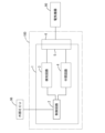
- FIG. 1 is an explanatory diagram conceptually showing the electrical configuration of an in-vehicle control system according to a first embodiment.
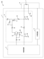
- FIG. 2 is a block diagram of an in-vehicle control system in which the detection circuit is more specifically embodied.
- FIG. 3 is an explanatory diagram showing the configuration of the control circuit, the detection circuit, and the intermediate circuit in more detail.
- FIG. 4 is an explanatory diagram showing a first example in which a connector is connected to a wiring board.
- FIG. 5 is an explanatory diagram showing a second example in which a connector is connected to a wiring board.
- FIG. 6 is a flowchart showing the flow of processing performed by the control circuit.
- FIG. 1 is an explanatory diagram conceptually showing the electrical configuration of an in-vehicle control system according to a first embodiment.
- FIG. 2 is a block diagram of an in-vehicle control system in which the detection circuit is more specifically embodied.
- FIG. 3 is an explanatory diagram showing the
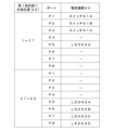
- FIG. 7 is an explanatory diagram showing the correspondence relationship between the resistance value of the first resistor, the electrical device, and the port.
- FIG. 8 is an explanatory diagram conceptually showing the electrical configuration of the vehicle-mounted control system according to the second embodiment.
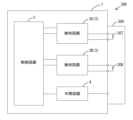
- FIG. 9 is an explanatory diagram conceptually showing the electrical configuration of the vehicle-mounted control system according to the third embodiment.
- FIG. 10 is an explanatory diagram showing the correspondence between combinations of resistance value information of a plurality of first resistor units and control patterns.
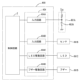
- FIG. 11 is an explanatory diagram conceptually showing the electrical configuration of an in-vehicle control system according to the fourth embodiment.
- a wiring board a connector for connecting an electrical device to the wiring board;
- a detection circuit provided on the wiring board; Equipped with The connector has a first resistor, The detection circuit is electrically connected to the first resistor portion when the connector is connected to the wiring board, and outputs a resistance value signal corresponding to a resistance value of the first resistor portion.
- the above-mentioned in-vehicle control system is configured so that the resistance value of the first resistor corresponds to the type of electrical equipment, and thus information for identifying the type of electrical equipment can be output from the detection circuit as a resistance value signal.
- the above-mentioned in-vehicle control system makes it possible to identify the type of electrical equipment on the wiring board side based on the resistance value signal. Therefore, the above-mentioned in-vehicle control system can easily realize a configuration in which the type of electrical equipment connected to the wiring board is identified on the wiring board side without providing an ECU that notifies information for identifying the type of electrical equipment.
- the above-mentioned in-vehicle control system makes it easy to simplify the configuration for outputting a resistance value signal in the detection circuit.
- the connector has a plurality of the first resistors,
- the connector can generate information for identifying the type of electrical device by combining the resistance value information of multiple first resistors. Therefore, the in-vehicle control system can easily realize a configuration that allows many types of electrical devices to be identified on the wiring board side.
- a control circuit is provided on the wiring board, The in-vehicle control system according to any one of [1] to [3], wherein the detection circuit outputs the resistance value signal in response to an instruction signal output from the control circuit.
- the control circuit can obtain a resistance value signal corresponding to the resistance value of the first resistor section by outputting an instruction signal.
- the control circuit can perform control corresponding to the resistance value signal output from the detection circuit. Therefore, in the above-mentioned in-vehicle control system, the resistance value of the first resistor portion is configured to correspond to the type of electrical equipment, so that the resistance value signal becomes a signal corresponding to the type of electrical equipment, and the control circuit can perform control according to the type of electrical equipment.
- the connector has a plurality of the first resistors, the detection circuit is electrically connected to each of the first resistor portions when the connector is connected to the wiring board, and outputs a resistance value signal corresponding to a resistance value of each of the first resistor portions;
- the in-vehicle control system according to [4] or [5], wherein the control circuit performs control according to a combination of resistance value information identified from each of the resistance value signals.
- the above-mentioned in-vehicle control system is configured so that the combination of resistance value information of the multiple first resistors corresponds to the type of electrical equipment, thereby allowing the control circuit to selectively perform control in accordance with many types of electrical equipment.
- the above-mentioned vehicle-mounted control system does not require the first resistor portion to be electrically connected to ground in the connector.
- the above-mentioned vehicle-mounted control system does not require the other end of the first resistor to be connected to the detection circuit, making it easy to simplify the connection structure between the connector and the detection circuit.
- First Embodiment 1 discloses an in-vehicle control system 100.
- the in-vehicle control system 100 includes a wiring board 1, a control circuit 2, a detection circuit 3, an intermediate circuit 4, a board-side connector 5, and a connector 6.
- the control circuit 2, the detection circuit 3, the intermediate circuit 4, and the board-side connector 5 are provided on the wiring board 1.
- the wiring board 1, the control circuit 2, the detection circuit 3, the intermediate circuit 4, and the board-side connector 5 configure an ECU (Electronic Control Unit).
- the wiring board 1 is configured by printing a conductive wiring pattern on an insulating board body such as resin.
- the control circuit 2 is a circuit that controls controlled objects such as loads mounted on the vehicle.
- the control circuit 2 includes, for example, a microcomputer.
- the control circuit 2 is configured as, for example, an MCU (Micro Controller Unit).
- the control circuit 2 includes a CPU, memory, etc.
- the control circuit 2 is mounted on the wiring board 1.
- the control circuit 2 has multiple input/output ports, and transmits and receives signals to and from external devices via these input/output ports.
- the board-side connector 5 is mounted on the wiring board 1.
- the board-side connector 5 is connected to the connector 6.
- the connector 6 is connected to an electric device 90.
- the electric device 90 may be, for example, a device that is controlled by the control circuit 2, such as a switch, a load, or an ECU.
- the load may be, for example, an LED, a display, a buzzer, a speaker, or a motor.
- the electric device 90 may be, for example, a device that outputs a signal to the control circuit 2.
- the electric device 90 may be a sensor or a status monitoring device that outputs a signal according to the on/off state of the monitored object. In this embodiment, an example is described in which the electric device 90 is a switch or an LED.
- the connector 6 is connected to the wiring board 1 via the board-side connector 5.
- the connector 6 connects the electrical device 90 to the wiring board 1 via the board-side connector 5.
- the connector 6 has a first resistor 7.
- the first resistor 7 is set to a resistance value according to the type of electrical device 90 connected to the connector 6.
- the detection circuit 3 is provided between the control circuit 2 and the board-side connector 5 (see FIG. 1).
- the detection circuit 3 is provided between the control circuit 2 and the connector 6 connected to the board-side connector 5.
- the detection circuit 3 is electrically connected to the first resistor portion 7 when the connector 6 is connected to the wiring board 1.
- the detection circuit 3 is electrically connected to both ends of the first resistor portion 7.
- the detection circuit 3 outputs a resistance value signal according to the resistance value of the first resistor section 7.
- the detection circuit 3 has a second resistor section 10 that is connected in series to the first resistor section 7 when the connector 6 is connected to the wiring board 1.
- the detection circuit 3 outputs a voltage obtained by dividing the power supply voltage Vcc between the first resistor section 7 and the second resistor section 10 as a resistance value signal.
- the detection circuit 3 outputs a resistance value signal in response to receiving an instruction signal output from the control circuit 2.
- the instruction signal is a high-level signal.
- the detection circuit 3 has a detection switch 11, capacitors 12 and 14, and a resistor section 13.
- the detection switch 11 is an N-channel MOSFET, but may be a switch other than an N-channel MOSFET.
- a power supply voltage Vcc is applied to the high-potential terminal (specifically, the drain) of the detection switch 11.
- One end of the second resistor section 10 is electrically connected to the low-potential terminal (specifically, the source) of the detection switch 11.
- One end of the first resistor section 7, one end of the capacitor 12, and one end of the resistor section 13 are electrically connected to the other end of the second resistor section 10. In other words, one end of the resistor section 13 is electrically connected to the path between the first resistor section 7 and the second resistor section 10.
- the other end of the resistor section 13 is electrically connected to one end of the capacitor 14.
- the other end of the first resistor section 7, the other end of the capacitor 12, and the other end of the capacitor 14 are electrically connected to ground 95.
- the detection switch 11 is turned on when an on signal (specifically, a high-level signal) is input to the input section (specifically, a gate), and is turned off when an off signal is input to the input section.
- the detection circuit 3 switches the detection switch 11 to the on state and outputs a resistance value signal via the resistor section 13. Note that the detection circuit 3 does not output a resistance value signal when the detection switch 11 is in the off state.
- the detection circuit 3 has a backflow prevention unit 15 and resistor units 16, 17, 18, and 19.
- the backflow prevention unit 15 prevents current from the power supply from flowing to the control circuit 2.
- the backflow prevention unit 15 is provided between the input unit of the detection switch 11 and the control circuit 2.
- the backflow prevention unit 15 is an NPN-type bipolar transistor.
- One end of the resistor unit 16 and one end of the resistor unit 17 are electrically connected to the base of the bipolar transistor.
- the other end of the resistor unit 17 and the emitter of the bipolar transistor are electrically connected to ground 95.
- the collector of the bipolar transistor is electrically connected to one end of the resistor unit 18.
- the other end of the resistor unit 18 is electrically connected to one end of the resistor unit 19 and the input unit of the detection switch 11.
- the other end of the resistor unit 19 is electrically connected to the high potential terminal of the detection switch 11.
- the instruction signal input to the detection circuit 3 is input to the base of the bipolar transistor. This causes current to flow between the collector and emitter of the bipolar transistor, turning on the detection switch 11.
- the intermediate circuit 4 is provided between the control circuit 2 and the board-side connector 5. That is, the intermediate circuit 4 is provided between the control circuit 2 and the connector 6 connected to the board-side connector 5.
- the intermediate circuit 4 outputs a signal to the connector 6 side in response to a signal being input from the control circuit 2 side, and outputs a signal to the control circuit 2 side in response to a signal being input from the connector 6 side.
- the intermediate circuit 4 has a switch drive circuit 31 and an LED drive circuit 32.
- the switch drive circuit 31 is, for example, a known switch drive circuit.
- the switch drive circuit 31 is provided corresponding to the ports P1, P2, P3, and P4 of the control circuit 2.
- the control circuit 2 controls the switches corresponding to the ports P1, P2, P3, and P4 by outputting drive instruction signals from the ports P1, P2, P3, and P4.
- the LED drive circuit 32 is, for example, a known LED drive circuit.
- the LED drive circuit 32 is provided corresponding to the ports P5, P6, P7, and P8 of the control circuit 2.
- the control circuit 2 controls the LEDs corresponding to the ports P5, P6, P7, and P8 by outputting drive instruction signals from the ports P5, P6, P7, and P8.
- FIG. 4 shows the state in which the connector 6A is connected to the wiring board 1.
- the switches 91A, 91B, 91C, and the LED 92A are connected to the connector 6A.
- the connector 6A connects the switches 91A, 91B, 91C, and the LED 92A to the wiring board 1.
- the connector 6A has a first resistor 7A.
- the resistance value of the first resistor 7A is set to a resistance value corresponding to the type of the electrical device 90 (i.e., the switches 91A, 91B, 91C, and the LED 92A).
- the resistance value of the first resistor 7A is, for example, 2 k ⁇ .
- the first resistor 7A is electrically connected to the detection circuit 3.
- FIG. 5 shows the state in which the connector 6B is connected to the wiring board 1.
- the LEDs 92A, 92B, 92C, and 92D are connected to the connector 6B.
- the connector 6B connects the LEDs 92A, 92B, 92C, and 92D to the wiring board 1.
- the connector 6B has a first resistor 7B.
- the resistance value of the first resistor 7B is set to a resistance value corresponding to the type of electrical device 90 (i.e., the LEDs 92A, 92B, 92C, and 92D).
- the resistance value of the first resistor 7B is, for example, 6 k ⁇ .
- the first resistor 7B is electrically connected to the detection circuit 3.
- the control circuit 2 performs the process shown in FIG. 6 when a predetermined start condition is met.
- the start condition may be receipt of a start command from the external ECU 96 (see FIG. 1), receipt of a start command output from the connector 6 when the connector 6 is connected to the wiring board 1, or another condition.
- the control circuit 2 When the process of FIG. 6 is started, the control circuit 2 first outputs an instruction signal from instruction port P11 (see FIG. 3) in step S101. The instruction signal output from instruction port P11 is input to the detection circuit 3. In response to the instruction signal being input, the detection circuit 3 outputs a resistance value signal corresponding to the first resistor section 7. The resistance value signal is input to the detection port P12 (see FIG. 3) of the control circuit 2. The control circuit 2 acquires the resistance value signal in step S102.
- the control circuit 2 may use R1 as the resistance value of the first resistor section 7 as is, or may use a value corrected based on the resistance value of the resistor section 13, temperature, etc., as the resistance value of the first resistor section 7.
- the control circuit 2 stores multiple control patterns in advance and performs control using the control pattern that corresponds to the identified resistance value of the first resistor unit 7.
- the control circuit 2 determines the resistance value of the first resistor portion 7 (specifically, the first resistor portion 7A) to be 2 k ⁇ .
- the control circuit 2 then performs control using a control pattern corresponding to 2 k ⁇ .
- the control pattern corresponding to 2 k ⁇ is included in the control patterns corresponding to 1 k ⁇ to 2.7 k ⁇ .
- the control pattern corresponding to 1 k ⁇ to 2.7 k ⁇ is a control pattern that controls the switches 91A, 91B, 91C, and LED 92A using signals output from ports P1, P2, P3, and P5.
- the control circuit 2 specifies the resistance value of the first resistor portion 7 (specifically, the first resistor portion 7B) as 6 k ⁇ .
- the control circuit 2 then performs control using a control pattern corresponding to 6 k ⁇ .
- the control pattern corresponding to 6 k ⁇ is included in the control patterns corresponding to 4.7 k ⁇ to 6.8 k ⁇ .
- the control pattern corresponding to 4.7 k ⁇ to 6.8 k ⁇ is a control pattern that controls LEDs 92A, 92B, 92C, and 92D using signals output from ports P5, P6, P7, and P8.
- the in-vehicle control system 100 is configured so that the resistance value of the first resistor section 7 corresponds to the type of electrical device 90, and thus information for identifying the type of electrical device 90 can be output from the detection circuit 3 as a resistance value signal.
- the in-vehicle control system 100 makes it possible to identify the type of electrical device 90 on the wiring board 1 side based on the resistance value signal. Therefore, the in-vehicle control system 100 can easily realize a configuration in which the type of electrical device 90 connected to the wiring board 1 is identified on the wiring board 1 side, without providing an ECU that notifies information for identifying the type of electrical device 90.
- control circuit 2 performs control according to a control pattern corresponding to the resistance value without identifying the type of electrical device 90, thereby performing control corresponding to the type of electrical device 90 connected to the wiring board 1.
- control circuit 2 may identify the type of electrical device 90 based on the resistance value signal, and perform control according to the identified type of electrical device 90.
- the in-vehicle control system 100 is configured to output the voltage obtained by dividing the power supply voltage Vcc between the first resistor section 7 and the second resistor section 10 as a resistance value signal, so it is easy to simplify the configuration for outputting the resistance value signal in the detection circuit 3.
- the control circuit 2 can obtain a resistance value signal corresponding to the resistance value of the first resistor section 7 by outputting an instruction signal.
- the control circuit 2 can perform control corresponding to the resistance value signal output from the detection circuit 3. Therefore, in the in-vehicle control system 100, the resistance value of the first resistor 7 is configured to correspond to the type of electrical device 90, so that the resistance value signal becomes a signal corresponding to the type of electrical device 90, and the control circuit 2 can perform control according to the type of electrical device 90.
- the vehicle control system 100 does not need to electrically connect the first resistor portion 7 to ground 95 in the connector 6.
- both ends of the first resistor portion 7 are connected to the detection circuit 3, but this is not limited to the configuration.
- a configuration in which only one end of the first resistor portion 7 is connected to the detection circuit 3 will be described. Note that the same components as those in the first embodiment are denoted by the same reference numerals and detailed description thereof will be omitted.
- the in-vehicle control system 200 of the second embodiment differs from the in-vehicle control system 100 of the first embodiment in that the other end of the first resistor unit 7 is electrically connected to ground 95 within the connector 206 as shown in FIG. 8, but is otherwise common.
- the ground 95 within the connector 206 is not particularly limited as long as it is connected to the body earth of the vehicle, and may be connected to the body earth via the electrical device 90 side or directly to the body earth.
- One end of the first resistor unit 7 is electrically connected to the detection circuit 3. More specifically, one end of the first resistor unit 7 is electrically connected to the other end of the second resistor unit 10, one end of the capacitor 12, and one end of the resistor unit 13.
- the in-vehicle control system 200 of the second embodiment does not need to connect the other end of the first resistor 7 to the detection circuit 3, making it easier to simplify the connection structure between the connector 206 and the detection circuit 3.
- the in-vehicle control system 300 of the third embodiment includes a wiring board 1, a control circuit 2, a plurality of detection circuits 3, an intermediate circuit 4, and a connector 306.
- the in-vehicle control system 300 of the third embodiment includes the board-side connector 5 described in the first embodiment.
- the plurality of detection circuits 3 include detection circuits 3A and 3B.
- the connector 306 has a plurality of first resistors 307, 308. Each of the first resistors 307, 308 is electrically connected to each detection circuit 3. Specifically, the first resistor 307 is electrically connected to the detection circuit 3A, and the first resistor 308 is electrically connected to the detection circuit 3B.
- the detection circuit 3 When the connector 306 is connected to the wiring board 1, the detection circuit 3 is electrically connected to each of the first resistor parts 307, 308, and outputs a resistance value signal corresponding to the resistance value of each of the first resistor parts 307, 308. Specifically, the detection circuit 3A outputs a resistance value signal corresponding to the resistance value of the first resistor part 307. In response to an instruction signal being input from the control circuit 2, the detection circuit 3A outputs a resistance value signal corresponding to the resistance value of the first resistor part 307. The detection circuit 3B outputs a resistance value signal corresponding to the resistance value of the first resistor part 308. In response to an instruction signal being input from the control circuit 2, the detection circuit 3B outputs a resistance value signal corresponding to the resistance value of the first resistor part 308.
- the control circuit 2 performs control according to a combination of resistance value information determined from the resistance value signals from the detection circuits 3A and 3B.
- the resistance value information may be any information indicating a resistance value, and may not be the resistance value itself but may be, for example, the voltage of the resistance value signal.
- the control circuit 2 determines the resistance value of the first resistor unit 307 based on the resistance value signal from the detection circuit 3A, and determines the resistance value of the first resistor unit 308 based on the resistance value signal from the detection circuit 3B.
- the control circuit 2 selects a control pattern according to the combination of the resistance value of the first resistor unit 307 and the resistance value of the first resistor unit 308, and performs control according to the selected control pattern.
- the control circuit 2 stores a table that specifies the correspondence between the combination of the resistance value of the first resistor unit 307 and the resistance value of the first resistor unit 308 and the control pattern, as shown in FIG. 10.
- the control circuit 2 selects control pattern A when the resistance value of the first resistor unit 307 is 1 k ⁇ or more and 2.7 k ⁇ or less, and the resistance value of the first resistor unit 308 is 1 k ⁇ or more and 2.7 k ⁇ or less.
- the control circuit 2 selects control pattern B when the resistance value of the first resistor unit 307 is 1 k ⁇ or more and 2.7 k ⁇ or less, and the resistance value of the first resistor unit 308 is 4.7 k ⁇ or more and 6.8 k ⁇ or less.
- the control circuit 2 selects control pattern C when the resistance value of the first resistor unit 307 is 4.7 k ⁇ or more and 6.8 k ⁇ or less, and the resistance value of the first resistor unit 308 is 1 k ⁇ or more and 2.7 k ⁇ or less.
- the control circuit 2 selects control pattern D when the resistance value of the first resistor unit 307 is 4.7 k ⁇ or more and 6.8 k ⁇ or less, and the resistance value of the first resistor unit 308 is 4.7 k ⁇ or more and 6.8 k ⁇ or less.
- the connector 306 can configure information for identifying the type of electrical device 90 by combining the resistance values of the multiple first resistors 307, 308. Therefore, the in-vehicle control system 300 can easily realize a configuration that allows many types of electrical device 90 to be identified on the wiring board 1 side.
- the in-vehicle control system 300 is configured so that the combination of resistance values of the multiple first resistors 307, 308 corresponds to the type of electrical device 90, allowing the control circuit 2 to selectively perform control in accordance with many types of electrical device 90.
- the electrical device includes a device that outputs a signal to the control circuit 2. Note that the same components as those in the first embodiment are given the same reference numerals and detailed description thereof will be omitted.
- the electrical device of the fourth embodiment includes a status monitor 491A, a sensor 491B, an LED 491C, and a buzzer 491D.
- the status monitoring device 491A monitors the on/off state of the object to be monitored, and outputs a signal corresponding to the on/off state to the control circuit 2.
- the object to be monitored is, for example, a right turn indicator.
- the switch 492A When the object to be monitored is in the on state, the switch 492A is in the on state, and when the object to be monitored is in the off state, the switch 492A is in the off state. Therefore, the status monitoring device 491A outputs a low level signal when the object to be monitored is in the on state, and outputs a high level signal when the object to be monitored is in the off state.
- Sensor 491B is a sensor that detects, for example, whether or not another vehicle is present diagonally to the right rear of the vehicle. If sensor 491B detects another vehicle, it outputs a detection signal to control circuit 2.
- LED491C is controlled by control circuit 2. LED491C is used for warnings.
- the buzzer 491D is controlled by the control circuit 2.
- the buzzer 491D is used for warnings.
- the in-vehicle control system 400 shown in FIG. 11 includes a control circuit 2 and an intermediate circuit 404.
- the intermediate circuit 404 includes an input circuit 404A, an input circuit 404B, an LED drive circuit 404C, and a buzzer drive circuit 404D.
- a signal output from the state monitoring device 491A is input to the control circuit 2 via the input circuit 404A.
- a signal input from the sensor 491B is input to the control circuit 2 via the input circuit 404B.
- the control circuit 2 controls the LED 491C by providing a control signal to the LED drive circuit 404C.
- the control circuit 2 drives the buzzer 491D by providing a control signal to the buzzer drive circuit 404D.
- the control circuit 2 selects a control pattern corresponding to these electrical devices using the methods described in the first to third embodiments above, and performs control using the selected control pattern. For example, when the control circuit 2 receives a detection signal from the sensor 491B while the right turn indicator is on, it turns on the LED 491C and sounds the buzzer 491D to warn the driver.
- the first resistance portion is configured to be positioned closer to the ground than the second resistance portion.
- the second resistance portion may be configured to be positioned closer to the ground than the first resistance portion.
- the control circuit switches the control pattern of an electrical device connected to a wiring board by a connector as a method for performing control corresponding to a resistance value signal.
- other methods may be adopted.
- the in-vehicle control system may be configured such that the control circuit identifies a control pattern corresponding to a resistance value signal, outputs a signal indicating the identified control pattern to an external ECU, and causes the external ECU to perform control according to the control pattern.
- the configuration in which "the control circuit identifies a control pattern corresponding to a resistance value signal, and outputs a signal indicating the identified control pattern to an external ECU" corresponds to "the configuration in which the control circuit performs control corresponding to a resistance value signal.”
- In-vehicle control system 200 In-vehicle control system 206... Connector 300
- In-vehicle control system 306 Connector 307... First resistor unit 308... First resistor unit 400
- In-vehicle control system 404 Intermediate circuit 404A
- Input circuit 404B Input circuit 404C
Landscapes
- Engineering & Computer Science (AREA)
- Theoretical Computer Science (AREA)
- Human Computer Interaction (AREA)
- Physics & Mathematics (AREA)
- General Engineering & Computer Science (AREA)
- General Physics & Mathematics (AREA)
- Mechanical Engineering (AREA)
- Testing Of Short-Circuits, Discontinuities, Leakage, Or Incorrect Line Connections (AREA)
Priority Applications (1)
| Application Number | Priority Date | Filing Date | Title |
|---|---|---|---|
| CN202480011933.2A CN120693586A (zh) | 2023-02-16 | 2024-01-26 | 车载用控制系统 |
Applications Claiming Priority (2)
| Application Number | Priority Date | Filing Date | Title |
|---|---|---|---|
| JP2023-022652 | 2023-02-16 | ||
| JP2023022652A JP2024116838A (ja) | 2023-02-16 | 2023-02-16 | 車載用制御システム |
Publications (2)
| Publication Number | Publication Date |
|---|---|
| WO2024171754A1 true WO2024171754A1 (ja) | 2024-08-22 |
| WO2024171754A9 WO2024171754A9 (ja) | 2025-06-19 |
Family
ID=92421586
Family Applications (1)
| Application Number | Title | Priority Date | Filing Date |
|---|---|---|---|
| PCT/JP2024/002321 Ceased WO2024171754A1 (ja) | 2023-02-16 | 2024-01-26 | 車載用制御システム |
Country Status (3)
| Country | Link |
|---|---|
| JP (1) | JP2024116838A (https=) |
| CN (1) | CN120693586A (https=) |
| WO (1) | WO2024171754A1 (https=) |
Citations (4)
| Publication number | Priority date | Publication date | Assignee | Title |
|---|---|---|---|---|
| JP2004320246A (ja) * | 2003-04-14 | 2004-11-11 | Olympus Corp | 撮像装置 |
| JP2013051753A (ja) * | 2011-08-30 | 2013-03-14 | Toyota Motor Corp | 車両から外部の被給電装置への給電用コネクタ、同コネクタの識別方法、同コネクタの識別システム、及び同コネクタを利用する給電システム、並びに同システムにおいて給電可能な車両 |
| JP2020012769A (ja) * | 2018-07-19 | 2020-01-23 | 東亜ディーケーケー株式会社 | 計測装置及び計測装置の本体装置 |
| JP2022145002A (ja) * | 2021-03-19 | 2022-10-03 | 古河電気工業株式会社 | 車載システム |
-
2023
- 2023-02-16 JP JP2023022652A patent/JP2024116838A/ja active Pending
-
2024
- 2024-01-26 CN CN202480011933.2A patent/CN120693586A/zh active Pending
- 2024-01-26 WO PCT/JP2024/002321 patent/WO2024171754A1/ja not_active Ceased
Patent Citations (4)
| Publication number | Priority date | Publication date | Assignee | Title |
|---|---|---|---|---|
| JP2004320246A (ja) * | 2003-04-14 | 2004-11-11 | Olympus Corp | 撮像装置 |
| JP2013051753A (ja) * | 2011-08-30 | 2013-03-14 | Toyota Motor Corp | 車両から外部の被給電装置への給電用コネクタ、同コネクタの識別方法、同コネクタの識別システム、及び同コネクタを利用する給電システム、並びに同システムにおいて給電可能な車両 |
| JP2020012769A (ja) * | 2018-07-19 | 2020-01-23 | 東亜ディーケーケー株式会社 | 計測装置及び計測装置の本体装置 |
| JP2022145002A (ja) * | 2021-03-19 | 2022-10-03 | 古河電気工業株式会社 | 車載システム |
Also Published As
| Publication number | Publication date |
|---|---|
| JP2024116838A (ja) | 2024-08-28 |
| CN120693586A (zh) | 2025-09-23 |
| WO2024171754A9 (ja) | 2025-06-19 |
Similar Documents
| Publication | Publication Date | Title |
|---|---|---|
| JP6488930B2 (ja) | 電子制御装置 | |
| US20230182752A1 (en) | Interface circuit, electronic control unit system, and methods of operating devices using an electronic control unit | |
| JP3315131B2 (ja) | 車載用電子機器 | |
| US8959256B2 (en) | Peripheral equipment and parallel bus system | |
| WO2024171754A1 (ja) | 車載用制御システム | |
| JPH10341524A (ja) | 車載用信号伝送装置と信号伝送方法及び車載用電力供給制御装置と電力制御方法及び車載ケーブル異常検出装置 | |
| JP3314922B2 (ja) | 負荷駆動システム及びその故障検出方法 | |
| JP2022527520A (ja) | 車両用センサ装置 | |
| US20070069695A1 (en) | Power controller for vehicle | |
| JP6562882B2 (ja) | 通信システム | |
| JP2020173137A (ja) | ハーネス故障診断装置及びハーネス故障診断方法 | |
| WO2010100754A1 (ja) | 検出システム及び電気システム | |
| US20190113559A1 (en) | Disconnection sensing circuit and electrical connection box | |
| US11498377B2 (en) | Systems and methods for determining an identity of a trailer | |
| KR101593513B1 (ko) | 전자 파킹 브레이크 시스템의 스위치 상태 판단 장치 | |
| WO2024176747A1 (ja) | コネクタ、及び車載用制御システム | |
| CN107003146B (zh) | 机动车中的电子装置 | |
| CN119325690A (zh) | 车载装置 | |
| US20250309884A1 (en) | Switch device, load drive system, and switch system | |
| JP2025148785A (ja) | モータ制御システム | |
| KR20000015704A (ko) | 자동차의 서스펜션 전자제어시스템 진단장치 | |
| KR100781811B1 (ko) | 차량용 경음기 | |
| KR100365234B1 (ko) | 경고등 구동 시스템 | |
| WO2023136128A1 (ja) | 電気機器及び車載システム | |
| JP2012218585A (ja) | 信号衝突検知装置、電子制御装置、及び、バスシステム |
Legal Events
| Date | Code | Title | Description |
|---|---|---|---|
| 121 | Ep: the epo has been informed by wipo that ep was designated in this application |
Ref document number: 24756605 Country of ref document: EP Kind code of ref document: A1 |
|
| WWE | Wipo information: entry into national phase |
Ref document number: 202480011933.2 Country of ref document: CN |
|
| NENP | Non-entry into the national phase |
Ref country code: DE |
|
| WWP | Wipo information: published in national office |
Ref document number: 202480011933.2 Country of ref document: CN |
|
| 122 | Ep: pct application non-entry in european phase |
Ref document number: 24756605 Country of ref document: EP Kind code of ref document: A1 |