WO2024171296A1 - コイル部品 - Google Patents
コイル部品 Download PDFInfo
- Publication number
- WO2024171296A1 WO2024171296A1 PCT/JP2023/004980 JP2023004980W WO2024171296A1 WO 2024171296 A1 WO2024171296 A1 WO 2024171296A1 JP 2023004980 W JP2023004980 W JP 2023004980W WO 2024171296 A1 WO2024171296 A1 WO 2024171296A1
- Authority
- WO
- WIPO (PCT)
- Prior art keywords
- protruding
- terminal
- recess
- wall
- coil component
- Prior art date
- Legal status (The legal status is an assumption and is not a legal conclusion. Google has not performed a legal analysis and makes no representation as to the accuracy of the status listed.)
- Ceased
Links
Images




Classifications
-
- H—ELECTRICITY
- H01—ELECTRIC ELEMENTS
- H01F—MAGNETS; INDUCTANCES; TRANSFORMERS; SELECTION OF MATERIALS FOR THEIR MAGNETIC PROPERTIES
- H01F27/00—Details of transformers or inductances, in general
- H01F27/28—Coils; Windings; Conductive connections
- H01F27/29—Terminals; Tapping arrangements for signal inductances
-
- H—ELECTRICITY
- H01—ELECTRIC ELEMENTS
- H01F—MAGNETS; INDUCTANCES; TRANSFORMERS; SELECTION OF MATERIALS FOR THEIR MAGNETIC PROPERTIES
- H01F27/00—Details of transformers or inductances, in general
- H01F27/02—Casings
-
- H—ELECTRICITY
- H01—ELECTRIC ELEMENTS
- H01F—MAGNETS; INDUCTANCES; TRANSFORMERS; SELECTION OF MATERIALS FOR THEIR MAGNETIC PROPERTIES
- H01F27/00—Details of transformers or inductances, in general
- H01F27/28—Coils; Windings; Conductive connections
- H01F27/2823—Wires
- H01F27/2828—Construction of conductive connections, of leads
-
- H—ELECTRICITY
- H01—ELECTRIC ELEMENTS
- H01F—MAGNETS; INDUCTANCES; TRANSFORMERS; SELECTION OF MATERIALS FOR THEIR MAGNETIC PROPERTIES
- H01F27/00—Details of transformers or inductances, in general
- H01F27/28—Coils; Windings; Conductive connections
- H01F27/29—Terminals; Tapping arrangements for signal inductances
- H01F27/292—Surface mounted devices
-
- H—ELECTRICITY
- H01—ELECTRIC ELEMENTS
- H01F—MAGNETS; INDUCTANCES; TRANSFORMERS; SELECTION OF MATERIALS FOR THEIR MAGNETIC PROPERTIES
- H01F27/00—Details of transformers or inductances, in general
- H01F27/28—Coils; Windings; Conductive connections
- H01F27/32—Insulating of coils, windings, or parts thereof
- H01F27/324—Insulation between coil and core, between different winding sections, around the coil; Other insulation structures
- H01F27/325—Coil bobbins
-
- H—ELECTRICITY
- H01—ELECTRIC ELEMENTS
- H01F—MAGNETS; INDUCTANCES; TRANSFORMERS; SELECTION OF MATERIALS FOR THEIR MAGNETIC PROPERTIES
- H01F5/00—Coils
- H01F5/04—Arrangements of electric connections to coils, e.g. leads
Definitions
- the present invention relates to coil components.
- Patent Document 1 discloses a coil component (100) in which a terminal protrusion hole (45) that opens downward is provided in the underside (40a) of an insulating frame body (24), and an electrode terminal member (47) protrudes downward from the terminal protrusion hole (45).
- the electrode terminal member (47) also has a mounting terminal (50) at one end.
- the coil component (100) is mounted on a board by bringing the underside of the mounting terminal (50) into contact with the board.
- the insulating frame (24) in the coil component (100) of Patent Document 1 is generally formed by injection molding. That is, the electrode terminal member (47) is placed in a mold that corresponds to the outer shape of the insulating frame (24), and liquid resin or the like is fed into the mold. More specifically, the shape of the mold corresponds to the shape of the part of the electrode terminal member (47) that is to protrude from the insulating frame (24) and the shapes of the top wall and surrounding wall of the terminal protrusion hole (45). The mold is arranged so that the surface of the electrode terminal member (47) is aligned with the outer surface of the electrode terminal member (47), and liquid resin is poured into the mold so that a part of the electrode terminal member (47) is embedded.
- the resin When resin is poured into a mold, if there is a gap between the outer surface of the electrode terminal member (47) and the corresponding surface of the mold, the resin may enter the gap and spread along the electrode terminal member (47) so as to cover a part of the mounting surface, which is the lower surface of the mounting terminal (50). If a part of the mounting surface is covered with resin, this is not preferable because it is likely to cause poor contact between the mounting terminal (50) and the board.
- the present invention was made in consideration of the above-mentioned problems, and provides a coil component with a structure that can suppress the amount of resin leaking out of the mold during injection molding. Furthermore, this problem is not limited to resin, but also occurs with other raw materials used in injection molding.
- the coil component of the present invention has a base portion, a terminal protruding from the underside of the base portion, and a coil electrically connected to the terminal, the underside of the base portion includes a lowest portion located at the lowest position and a protruding surface located above the lowest portion, and the terminal has an embedded portion embedded in the base portion, a protruding portion that is continuous from the embedded portion and protrudes downward from the protruding surface and is linear, a bent portion that is continuous from the protruding portion and is bent toward the side of the base portion, and a mounting portion that is continuous from the bent portion and includes a mounting surface facing downward.
- the protruding portion protruding from the protruding surface is straight. If the protruding portion is straight, the mold and the protruding portion can be aligned during injection molding, making the gap between the mold and the protruding portion sufficiently small, compared to when the protruding portion is curved. This is because if the protruding portion is straight, there is less variation in the shape of the protruding portion compared to when the protruding portion is curved. This makes it possible to suppress the amount of resin that spreads through the gap.
- the coil component of the present invention can reduce the gap between the mold and the outer surface of the terminal during injection molding. This can prevent the resin from spreading onto the mounting surface of the terminal.
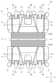
- FIG. 1 is a perspective view showing an example of a coil component according to a first embodiment of the present invention.
- FIG. 2 is an exploded perspective view of the coil component according to the first embodiment.
- 1 is a top view of a coil component according to a first embodiment, in which an upper core, a terminal, and an opening of a terminal recess are indicated by dotted lines.
- FIG. 2 is a bottom view of the coil component according to the first embodiment. 2 is a vertical cross-sectional view taken at the center in the width direction of the coil component according to the first embodiment.
- FIG. Fig. 6(a) is an enlarged view of the terminal and its vicinity in Fig. 5.
- Fig. 6(b) is an enlarged view of the terminal and its vicinity in Fig. 4.
- 1 is a front view of a coil component according to a first embodiment, in which the outer shapes of a terminal recess and a recess are indicated by dotted lines;
- the various components of the coil component of the present invention do not need to be independent entities, and it is acceptable for multiple components to be formed as a single member, for one component to be formed from multiple members, for one component to be part of another component, or for part of one component to overlap with part of another component, etc.
- the front-rear, left-right, top-bottom directions are defined as shown in the figure. However, this is defined for convenience in order to easily explain the relative relationship between components, and does not limit the directions during manufacture or use of the product embodying the present invention.
- the lower side is the board side when the coil component is mounted on a board (not shown), and the top-bottom direction coincides with the height direction of the coil component.
- the front-rear direction coincides with the winding axis direction of the coil component in the first embodiment.
- the left-right direction coincides with the width direction of the coil component.
- the winding axis direction or the width direction refers to the winding axis direction of the coil component or the width direction of the coil component, respectively.
- the direction from the outer edge of the coil component toward the center is referred to as the inside, inward, or inward direction
- the direction from the center of the coil component toward the outer edge is referred to as the outside, outward, or outward direction.
- the term "flat surface” as used herein means a shape that is physically formed with a flat surface as a goal, and it is not necessarily required that the surface be a geometrically perfect flat surface.
- FIG. 1 is a perspective view showing an example of a coil component according to a first embodiment of the present invention.
- the coil component 100 has a base portion 10, a terminal 20 protruding from the lower surface of the base portion 10, and a coil 30 electrically connected to the terminal 20.
- the lower surface of the base portion 10 includes a lowermost portion located at the bottom and a protruding surface 13a (in this embodiment, a top wall defining a terminal recess 13 described later) located above the lowermost portion.
- the terminal 20 has an embedded portion 21b, a protruding portion 21a, a bent portion (a first bent portion 22), and a mounting portion 25.
- the embedded portion 21b is embedded in the base portion 10.
- the protruding portion 21a is continuous with the embedded portion 21b and protrudes downward from the protruding surface 13a, and is linear.
- the first bent portion 22 is continuous from the protruding portion 21a and bent toward the side of the base portion 10.
- the mounting portion 25 includes a mounting surface 25a facing downward and is continuous from the first bent portion 22.
- the die and the protrusion 21a can be aligned sufficiently during injection molding, and the gap between the die and the protrusion 21a can be reduced, compared to when the protrusion 21a is curved. This is because if the protrusion 21a is linear, the variation in the shape of the protrusion 21a can be suppressed compared to when the protrusion 21a is curved. This reduces the amount of resin that spreads through the gap. In particular, it is possible to prevent the resin from reaching the mounting surface 25a of the mounting portion 25 through the gap along the surface of the terminal 20 (such as the inner surface 21a1 described later).
- the protruding portion 21a protrudes downward from the protruding surface 13a disposed above the lowest portion of the base portion 10.
- the distance along the surface of the terminal 20 between the upper end of the protruding portion 21a and the mounting surface 25a is sufficiently large compared to the case where the protruding portion 21a protrudes from a height approximately equal to the lowest portion. This makes it possible to prevent the resin that leaks and spreads during injection molding from reaching the mounting surface 25a.
- Fig. 1 is a perspective view of the coil component 100 of this embodiment.
- the coil component 100 is a device having a coil 30 and is a component that forms part of a circuit.
- the coil component 100 is a transformer.
- Other examples of coil components include an antenna and an inductor.
- the base portion 10 is a seat portion in which terminals, which will be described later, are embedded and hold the terminals.
- the base portion 10 is formed of an insulating material such as resin. More specifically, as will be described later, the base portion 10 is formed by injection molding of an insulating material. In the following description, it is assumed that the base portion 10 is molded using resin as the insulating material. As shown in FIG.
- the base portion 10 in this embodiment has a bobbin portion 11 and a pair of flange portion receiving portions 12 .
- the bobbin portion 11 is a portion that becomes a winding axis of the coil 30 described later.
- the bobbin portion 11 has a space that is defined by a pair of side plates 11b, 11b and a bottom plate 11c that are spaced apart in the width direction of the coil component 100 and that is open at the top.
- a winding core portion 42a of a lower core 42 described later is accommodated in the space.
- a partition 11a is provided so as to go substantially around the bobbin portion 11 in the winding axis direction.
- the partition 11a is a plate-shaped flange that is provided across the pair of side plates 11b and the bottom plate 11c and protrudes outward from the bobbin portion 11.
- the partition 11a separates the winding positions of a primary coil 30a and a secondary coil 30b described later.
- a pair of flange accommodating portions 12 are formed integrally with the bobbin portion 11 at both ends of the bobbin portion 11 in the winding axis direction.
- the flange accommodating portion 12 has a space defined by a bottom plate 12a, a wall portion 14, a flange side portion 12b, and an inner wall 12c.
- a flange 42b of a lower core 42 which will be described later, is accommodated in the space.
- the space opens upward, and is adjacent to and communicates with a space provided in the bobbin portion 11 in which a winding core portion 42a is accommodated. That is, the base portion 10 has an overall concave shape that opens upward, and has a space that accommodates the core 40 (particularly the lower core 42).
- the wall portion 14, the bottom plate 12a and the flange side portion 12b are integrally formed.
- the flange side portions 12b are spaced apart in the width direction across the core 40.
- the flange side portions 12b are integrally formed with the inner wall 12c and the side plate 11b. 5 and described later, a portion of the terminal 20 is embedded in the bottom of the flange accommodating portion 12. In this embodiment, the terminal 20 is embedded in the lower portion of the wall portion 14.
- the lowermost part of the base part 10 is a surface or point located at the lowest position of the base part 10.
- the lowermost part of the base part 10 is a surface or point located at the lowest position of the base part 10 in the vicinity where the terminal 20 is embedded.
- the vicinity where the terminal 20 is embedded refers to the flange accommodating part 12 in which the terminal 20 is embedded, and preferably refers to the surrounding wall 13b forming the terminal recess described later.
- the lowermost part of the base part 10 in this embodiment is the lower surface of the flange accommodating part 12 (the downward protruding region 11d described later) and is the opening end (lower end) of the terminal recess 13 described later.
- the protruding surface 13a is a surface from which the terminal 20 protrudes.
- the protruding surface 13a is a top wall (bottom portion disposed above) of the terminal recess 13 described later.
- the protruding surface 13a is disposed around the base end of the terminal (the protruding portion 21a described later). That is, the protruding surface 13a is disposed on the side of the base end of the protruding portion 21a.
- the protruding surface 13a is disposed so as to surround the base end of the protruding portion 21a.
- the base end of the protruding portion 21a and a part of the peripheral wall 13b described later are spaced apart from each other.
- the protruding surface 13a surrounds the base end of the terminal 20 in three directions (both outsides in the width direction and inside in the winding axis direction).
- the protruding surface 13a may be disposed outside the base end of the protruding portion 21a in one direction (either the width direction or the winding axis direction), or may surround the entire periphery of the base end of the protruding portion 21a.
- the coil 30 in this embodiment is formed by winding a coil wire.
- the coil 30 is formed by winding a coil wire directly or indirectly around the winding core portion 42a of the lower core 42 and the bobbin portion 11. In other words, a part of the core 40 and the bobbin portion 11 are disposed inside the coil 30.
- the coil 30 may be an air-core coil that does not have the core 40 or the bobbin portion 11 inside.
- the coil component 100 in this embodiment is a transformer, and has a primary coil 30a and a secondary coil 30b as the coil 30.
- the primary coil 30a and the secondary coil 30b in this embodiment are each formed of two coil wires. In this embodiment, the primary coil 30a is an input side coil, and the secondary coil 30b is an output side coil.
- the primary coil 30a is wound in front of the partition 11a in the bobbin part 11, and the secondary coil 30b is wound in the bobbin part 11 behind the partition 11a.
- two or more coil wires may be wound as the primary coil 30a or the secondary coil 30b, or instead of this embodiment, only one coil wire may be wound.
- the coil wire (pulled-out portion 31) is pulled out from the coil 30 to the front side or the rear side.
- the pulled-out portion 31 is connected to the connecting portion 26 (described later) along the shape of the lower surface of the base portion 10.
- the pulled-out portion 31 connected to the connecting portion 26 of the second terminal 20b passes through a groove formed on the lower surface of the flange housing portion 12 and extending along the winding axis direction.
- a plurality of downward protruding regions 11d are formed on the lower surface of the base portion 10.
- the downward protruding region 11d is a part of the base portion 10 that protrudes downward from the top wall of the groove.
- the groove is defined by the two downward protruding regions 11d so as to be sandwiched between them.
- the pulled-out portion 31 connected to the first terminal 20a or the third terminal 20c is wired so as to be along the side surface of the downward protruding region 11d.
- each of a pair of walls 14, 14 spaced apart in the winding axis direction has three terminals 20 (a first terminal 20a, a second terminal 20b, and a third terminal 20c).
- the first terminal 20a and the third terminal 20c differ from each other in that they have one connecting portion 26, which will be described later, and the second terminal 20b has two connecting portions 26.
- the terminal 20 has the connecting portion 26, a base end portion 24, an intermediate portion 21, and a mounting portion 25.
- the connection portion 26 is a part to which an end of the coil wire (draw-out portion 31) drawn out from the coil 30 is connected.
- the coil component 100 of this embodiment is manufactured by entangling an end of the draw-out portion 31 to the connection portion 26 during the manufacturing process, and welding the connection portion 26 and the end of the draw-out portion 31 together.
- the connection portion 26 and the draw-out portion 31 may be joined by soldering or the like.
- the mounting portion 25 is a part of the terminal 20 that is grounded to a substrate (not shown) when the coil component 100 is mounted.
- the mounting portion 25 includes a mounting surface 25a that faces downward, and the mounting surface 25a and the substrate are in surface contact with each other.
- the mounting portion 25 and the substrate are joined by soldering or the like.
- an upper part (embedded part 21b) of the intermediate part 21 is embedded in the base part 10, and a lower part (protruding part 21a) is exposed from the base part 10.
- the protruding part 21a protrudes downward from a protruding surface 13a of the base part 10, which will be described later.
- “downward” refers to a direction having a vertical component, and includes a direction parallel to the vertical direction, but is not limited to a direction parallel to the vertical direction.
- the protruding part 21a protrudes from the base part 10 at an angle with respect to the vertical direction, as will be described later.
- the embedded portion 21b is a part of the end portion (including the second bent portion 23, the intermediate portion 21, the first bent portion 22, and the mounting portion 25 described later) extending from the base end portion 24 to the mounting portion 25, which is embedded in the base portion 10.
- the embedded portion 21b is a part of the upper side of the intermediate portion 21, but instead of this embodiment, the embedded portion 21b may be the second bent portion 23. In that case, the entire intermediate portion 21 becomes the protruding portion 21a.
- the protruding portion 21a being linear means that the entire protruding portion 21a is substantially linear, and is not limited to being completely linear.
- the shape of the protruding portion 21a may be a substantially linear shape that is slightly curved more gently than the curved shape of the first bent portion 22. More specifically, the protruding portion 21a may be slightly curved laterally to the extent that an inner surface 21a1 of the protruding portion 21a, which will be described later, is substantially flat.
- the protrusion 21a has an inner surface 21a1 and an outer surface 21a2 that face each other.
- the inner surface 21a1 of the protrusion 21a is a surface that faces inward in the winding axis direction
- the outer surface 21a2 is a surface that faces outward in the winding axis direction.
- the inner surface 21a1 and the outer surface 21a2 of the protrusion 21a are main surfaces of the protrusion 21a.
- the inner surface 21a1 of the protrusion 21a faces the inside of the terminal recess 13.
- the outer surface 21a2 faces upward, and the inner surface 21a1 faces downward.
- the terminal 20 is bent at the first bent portion 22 between the mounting portion 25 and the intermediate portion 21, and at the second bent portion 23 between the intermediate portion 21 and the base end portion 24.
- the first bent portion 22 is bent so that the mounting portion 25 faces the side of the base portion 10 from the intermediate portion 21. That is, the bending direction of the first bent portion 22 is the direction from the lower end of the intermediate portion 21 (the base end of the first bent portion 22) toward the side of the base portion 10.
- the side is a direction that includes a component in the width direction or the winding axis direction, and includes a direction perpendicular to the up-down direction, but is not limited to a direction perpendicular to the up-down direction.
- the bending direction of the first bent portion 22 is outward in the winding axis direction.
- the second bent portion 23 is bent in a direction in which the intermediate portion 21 faces downward from the base end portion 24.
- the bending direction of the second bent portion 23 is downward.
- the downward direction is a direction that has a vertical component, and is not limited to a direction parallel to the up-down direction.
- connection portion 26 and the other end including the mounting portion 25 branch off from the base end 24 and extend in the front-rear direction.
- the second terminal 20b which has two connection portions 26 and one mounting portion 25, branches off into three at the base end 24, with the connection portions 26 located on both outer sides in the width direction and the mounting portion 25 located in the center.
- the first terminal 20a and the third terminal 20c which each have one connection portion 26 and one mounting portion 25, have the connection portions 26 located on the outer sides in the width direction and the mounting portion 25 located on the inner sides.
- each wall portion 14 may have one terminal 20 or two or more terminals 20.
- the terminal 20 has a shape obtained by bending a flat plate and a rectangular cross section, but is not limited thereto.
- the terminal may have a shape obtained by bending a wire or a rod-shaped member, in which case a part of the wire or rod-shaped member is crushed to form a flat surface, and the flat surface may be used as the mounting surface 25a (see FIG. 6(a)).
- the core 40 is made of a magnetic material such as ferrite. As shown in FIG. 2, in this embodiment, the core 40 is made of two core members (upper core 41 and lower core 42). The core 40 may be made of one core member, or may be made of two or more core members. In this embodiment, the upper core 41 is a plate-shaped I-shaped core, and the lower core 42 is a U-shaped core, which are combined to form a closed magnetic circuit, but this is not limited to this. Two U-shaped cores may be combined, or the upper core 41, which is a U-shaped core, and the lower core 42, which is an I-shaped core, may be combined.
- the lower core 42 includes a winding core 42a around which the coil 30 is wound, and a pair of flanges 42b formed at both ends of the winding core 42a in the winding axis direction.
- the flanges 42b protrude upward from the upper surface of the winding core 42a. As shown in FIG. 3, the flanges 42b protrude on both sides in the width direction from the winding core 42a.
- both corners (a pair of corners extending in the vertical direction and spaced apart in the width direction) on the inner side in the winding axis direction of each flange 42b are recessed in accordance with the outer shape of the inner wall 12c.
- the upper surface of the flanges 42b is disposed above the upper end of the inner wall 12c.
- the shape of the winding core 42a in the lower core 42 is plate-shaped. As shown in FIG. 2, the upper corners of the winding core 42a along the winding axis direction are chamfered.
- the upper core 41 has a plate shape that is thin in the height direction. As shown in Fig. 3, the upper core 41 has dimensions larger than the lower core 42 in the winding axis direction and width direction. The dimensions of the upper core 41 and the maximum dimensions of the lower core 42 in these directions may be approximately the same. Both ends of the upper core 41 are disposed between a pair of flange side portions 12b (see Fig. 2). As shown in Fig.
- the upper surface of the upper core 41 is disposed above the upper surface of the base portion 10, and the upper portion of the upper core 41 is disposed outside the base portion 10.
- the lower surface of the upper core 41 and the upper surface of the lower core 42 (flange portion 42b), as well as the lower surface of the lower core 42 and the bottom plate 11c of the base portion 10 are bonded with an adhesive, but they do not have to be bonded to each other and may simply have portions abutting each other.
- the base portion 10 has a side wall 13b1 disposed outside the protruding portion 21a in the bending direction of the first bent portion 22 (outward in the winding axis direction).
- the protruding portion 21a and the side wall 13b1 overlap in an overlapping region (first overlapping region 51) when viewed from below.
- the protruding portion 21a and the side wall 13b1 are in contact with each other in the first overlapping region 51.
- the side wall 13b1 is a part of the lower part of the base portion 10, which overlaps with part or all of the protruding portion 21a in the winding axis direction and is a part that is arranged on the outer side of the protruding portion 21a in the winding axis direction. In this embodiment, it is a part of the peripheral wall 13b that defines the terminal recess 13 described later and is arranged on the outer side in the winding axis direction.
- the side wall 13b1 has an inner surface 13b2 that faces inward in the winding axis direction and an outer surface 13b3 that faces outward in the winding axis direction and faces the inner surface 13b2.
- the outer surface 13b3 of the side wall 13b1 is a part of the side surface of the base portion 10 (wall outer surface 14b described later), and the outer surface 13b3 of the side wall 13b1 and the side surface of the base portion 10 are on the same plane.
- the outer surface 13b3 of the side wall 13b1 extends in the vertical direction or is arranged at an angle with respect to the vertical direction so as to be continuously arranged on the outer side in the winding axis direction from the upper end to the lower end. Further, an outer surface 13b3 of the side wall 13b1 is flat, and no recess that opens to the side is provided on the outer surface 13b3.
- intermediate portion 21 (protruding portion 21a) is inclined obliquely with respect to the up-down direction, and the lower end of intermediate portion 21 is disposed further outward in the winding axis direction than the upper end thereof. Therefore, in bottom view, protruding portion 21a overlaps with side wall 13b1 that is disposed outward of protruding portion 21a in the winding axis direction.
- the part of the terminal 20 and the side wall 13b1 are arranged so as to overlap in the up-down direction when viewed in a vertical cross section as shown in Fig. 6(a).
- a top view or a bottom view described below it is not limited to whether a certain aspect can be confirmed with the direct eye, and it is sufficient that the aspect can be confirmed in a cross section such as a vertical cross section.
- the protrusion 21a and the side wall 13b1 are in contact with each other in the first overlap region 51 means that an outer surface 21a2 of the protrusion 21a and an inner surface 13b2 of the side wall 13b1 are in contact with each other in an opposing manner.
- the protrusion 21a and the side wall 13b1 are in contact with each other over almost the entire first overlap region 51.
- the protrusion 21a and the side wall 13b1 may be separated from each other in a very small part due to voids or the like generated during injection molding.
- the entire outer surface 21a2 of the protruding portion 21a is covered by the side wall 13b1 and is in contact with the side wall 13b1, but is not limited thereto. Only a part of the upper side of the outer surface 21a2 of the protruding portion 21a may be covered by the side wall 13b1, and an upper portion of the protruding portion 21a that overlaps with the side wall 13b1 in a bottom view may be in contact with the side wall 13b1.
- the mounting portion 25 and the first bent portion 22 do not overlap with the side wall 13b1 in a bottom view, and are disposed outward in the winding axis direction from the outer surface 13b3 of the side wall 13b1.
- the wall outer surface 14b described later extends parallel to the vertical direction or is formed inclined obliquely outward downward, with the upper end of the wall outer surface 14b being located more inward in the winding axis direction than the lower end.
- the wall outer surface 14b does not have a recess, or if a recess is provided, the recess is a recess whose entire interior is visible when viewed from above.
- the wall outer surface 14b is configured with a part or all of the wall outer surface 14b extending parallel to the vertical direction, or a part or all of the wall outer surface 14b that is visible when viewed from above.
- the fact that the wall outer surface 14b is visible when viewed from above means that in the absence of other members such as the wire connection portion 26, a part of the wall outer surface 14b is not covered by another part of the wall outer surface 14b and cannot be seen.
- the mounting portion 25 and the side wall 13b1 overlap in a second overlapping region (second overlapping region 52) when viewed from below.
- the mounting portion 25 and the side wall 13b1 are in contact with each other in the second overlapping region 52.
- the lower end of the side wall 13b1 has a predetermined thickness in the roll axis direction and has a flat lower surface.
- the overlapping of the mounting portion 25 and the side wall 13b1 in the second overlapping region 52 means that the upper surface of the mounting portion 25 facing upward and the lower surface of the side wall 13b1 face each other and are in contact with each other.
- the mounting portion 25 and the side wall 13b1 are in contact with each other over the entire second overlapping region 52.
- the mounting portion 25 and the side wall 13b1 may be separated from each other in a very small part due to voids or the like generated during injection molding.
- the protruding portion 21a is disposed at an angle with respect to the vertical direction, but is not limited thereto.
- the protruding portion 21a may be disposed parallel to the vertical direction. In this case, the side wall 13b1 and the protruding portion 21a do not overlap each other in a bottom view, and the side wall 13b1 and the mounting portion 25 overlap each other in the second overlap region 52.
- first bent portion 22 and the side wall 13b1 overlap in the third overlap region 53 in a bottom view, and the first bent portion 22 and the side wall 13b1 are in contact with each other throughout the entire third overlap region 53.
- the contact between the first bent portion 22 and the side wall 13b1 means that the upper surface 22a facing the bending center in the first bent portion 22 and a part of the surface of the side wall 13b1 (the boundary between the outer surface 13b3 and the lower surface) are in contact with each other.
- the first overlap region 51 and the third overlap region 53, and further the third overlap region 53 and the second overlap region 52 are adjacent to each other to form a continuous overlap region.
- the first overlap region 51 , the second overlap region 52 and the third overlap region 53 may be collectively referred to as the overlap region 50 .
- the upper surface of the first bent portion 22 may be substantially a line.
- the second overlap region 52 and the first overlap region 51 are substantially adjacent to each other and continuous with each other.
- the lower surface of the base portion 10 is provided with a terminal recess 13 surrounded by a peripheral wall 13b and a protruding surface 13a.
- the protruding portion 21a protrudes from the protruding surface 13a, which is the top wall of the terminal recess 13, and is surrounded by the peripheral wall 13b.
- a part of the peripheral wall 13b is a side wall 13b1 that contacts the protruding portion 21a.
- another part of the peripheral wall 13b is disposed near the protruding portion 21a and is spaced apart from the protruding portion 21a.
- the distance between the base end of the protruding portion 21a and the base end side of the mounting portion 25 along the inner surface 21a1 and the lower surface (facing downward) of the first bent portion 22, and the shortest distance between the base end of the protruding portion 21a and the base end side of the mounting portion 25 along the side end surface (facing outward in the width direction) of the protruding portion 21a and the side end surface of the first bent portion 22 are increased. This makes it possible to prevent the resin from running along the inner surface 21a1 or the side end surface of the terminal recess 13 and reaching the mounting surface 25a during injection molding.
- the terminal recess 13 is a bottomed recess in which the terminal 20 (protrusion 21 a) is disposed and which is provided so as to open downward on the lower surface of the base portion 10.
- the shape of the opening of the peripheral wall 13b is rectangular when viewed from below, but it may be circular or polygonal.
- the surrounding wall 13b surrounds the protruding portion 21a on all four sides (both sides in the winding axis direction and the width direction) without any gaps.
- the side wall 13b1 and the protruding portion 21a are in contact with each other, as described above and illustrated in FIG.
- the surrounding wall 13b is disposed in the vicinity of the protruding portion 21a, as illustrated in FIG. 5, and the terminal recess 13 is provided in the wall portion 14, and the surrounding wall 13b is a part of the lower portion of the wall portion 14.
- the distance between the surrounding wall 13b and the protruding portion 21a is smaller than the distance between the terminal 20 (protruding portion 21a) protruding from the terminal recess 13 and the adjacent terminal 20 (protruding portion 21a).
- the distance between the surrounding wall 13b and the protruding portion 21a is equal to or less than twice the thickness (dimension in the winding axis direction) of the protruding portion 21a.
- the protruding portion 21a being separated from the other part of the peripheral wall 13b means that the protruding portion 21a is separated from the peripheral wall in three directions. Specifically, the protruding portion 21a is separated from a part (opposing portion 13b4) of the peripheral wall 13b that is disposed on the inside of the protruding portion 21a in the roll axis direction and faces the inner surface 13b2 of the protruding portion 21a.
- the protruding portion 21a is also separated from a part (side portion 13b5) of the peripheral wall that is disposed on both outsides of the protruding portion 21a in the width direction and faces the side end surfaces of the protruding portion 21a.
- the distance between the protruding portion 21a (particularly the base end of its inner surface 21a1) and the facing portion 13b4 (particularly the base end) is greater than the distance between the protruding portion 21a (particularly the base end of its side end surface) and each of the pair of side portions 13b5 (particularly the base end).
- the amount of resin leaking along the inner surface 21a1 of the protruding portion 21a during injection molding is greater than the amount of resin leaking along the side end surface of the protruding portion 21a. This is because the width (dimension in the width direction) of the inner surface 21a1 of the protruding portion 21a is greater than the side end surface (dimension in the winding axis direction) of the protruding portion 21a. Since the distance between the protruding portion 21a and the facing portion 13b4 is greater than the distance between the protruding portion 21a and the side portion 13b5, the resin leaking along the inner surface 21a1 of the protruding portion 21a during injection molding is prevented from adhering to the facing portion 13b4 and filling the terminal recess 13. Furthermore, since the leaked resin is unlikely to adhere to the opposing portion 13b4, the covering portion 13c, which will be described later, can be provided in a desired thickness.
- the height (vertical distance) of protruding surface 13a with respect to the lowest part is greater than the vertical dimension of first bent portion 22.
- the distance between protruding surface 13a and mounting surface 25a is ensured to be long, and the resin that flows out during injection molding can be prevented from reaching mounting surface 25a.
- the height of the protruding surface 13a based on the lowest part is the depth of the terminal recess 13, and is the height to the protruding surface 13a based on the lower end of the surrounding wall 13b.
- the dimension of the first bent portion 22 in the vertical direction is the height dimension to the upper end of the first bent portion 22 based on the lower end of the first bent portion 22.
- the dimension of the protruding portion 21a in the vertical direction is larger than the dimension of the first bent portion 22 in the vertical direction.
- the dimension of the protrusion 21a in the vertical direction is the height dimension from the bottom end of the protrusion 21a to the top end of the protrusion 21a. It is preferable that the dimension of the protrusion 21a in the vertical direction is equal to or smaller than the depth of the terminal recess 13.
- the entire protrusion 21a is disposed inside the terminal recess 13 in this manner, so that the protrusion 21a can be sufficiently protected by the surrounding wall 13b.
- the dimension of the protrusion 21a in the vertical direction may be larger than the depth of the terminal recess 13, and the lower part of the protrusion 21a may be disposed outside the envelope volume of the terminal recess 13.
- the bending angle ⁇ 1 of the first bent portion 22 is smaller than 90 degrees, and the protruding portion 21a is disposed obliquely with respect to the mounting portion 25. That is, the angle that a part of the terminal 20 from the mounting portion 25 to the intermediate portion 21 makes with the first bent portion 22 as the center is an obtuse angle (an angle larger than 90 degrees).
- the terminal 20 from the protruding portion 21a to the mounting portion 25 has elasticity that can be easily deformed by an external force having a vertical component.
- the protruding portion 21a, the first bent portion 22, and the mounting portion 25 are deformable so that the bending angle of the first bent portion 22 becomes larger or smaller.
- the protruding portion 21a and the mounting portion 25 are easily deformed to match the shape of the mold for injection molding, and resin leakage during injection molding is better prevented.
- the protruding portion 21a obliquely with respect to the vertical direction, the length along the inner surface 21a1 of the protruding portion 21a from the upper end to the lower end of the surface can be secured large with respect to the height dimension of the protruding portion 21a. This makes it possible to more effectively prevent the resin leaking during injection molding from reaching the mounting surface 25a.
- the bending angle is the angle at which the conductive member is bent when a plate-like or linear conductive member is bent to form a bent portion (first bent portion 22 or second bent portion 23).
- the bending angle is the central angle of the bent portion, and is the angle between the boundary surface between the bent portion of the terminal 20 after bending and a part of the terminal 20 adjacent to the bent portion on one side, and the boundary surface between the bent portion and a part of the terminal 20 adjacent to the bent portion on the other side.
- the bending angle ⁇ 1 is the angle between the boundary surface between the first bent portion 22 and the protruding portion 21a, and the boundary surface between the first bent portion 22 and the mounting portion 25. It can also be said that the bending angle ⁇ 1 is the supplementary angle of the angle between a part of the terminal 20 from the mounting portion 25 to the protruding portion 21a (middle portion 21) with the first bent portion 22 as the center.
- the bending angle ⁇ 2 of the second bent portion 23 is also smaller than 90 degrees, and the intermediate portion 21 is also disposed at an angle with respect to the base end portion 24.
- a portion from the intermediate portion 21 to the base end portion 24 also has elasticity that allows it to be deformed by an external force having a vertical component. That is, in this embodiment, a portion of the terminal from the base end portion 24 to the mounting portion 25 has a restoring force that deforms into a flat shape as a whole due to an external force having a vertical component and attempts to restore it to its original shape by its own elasticity.
- the terminal 20 is formed such that a portion including the mounting portion 25 and the protruding portion 21a and the connection portion 26 to which the end of the coil wire (drawing portion 31) drawn from the coil is connected are branched at the base end 24.
- the terminal 20 is bent at a second bent portion (second bent portion 23) located between the base end 24 and the protruding portion 21a.
- the base end 24 has a lower surface (base end lower surface 24a) that is continuous with the mounting surface 25a and faces downward.
- the base end underside 24a and the mounting surface 25a being continuous means that the base end underside 24a is smoothly continuous with the mounting surface 25a via the surface of the second bent portion 23, the surface of the intermediate portion 21 including the inner surface 21a1 of the protruding portion 21a, and the surface of the first bent portion 22.
- the area that becomes the base end underside 24a and the area that becomes the mounting surface 25a are flush with each other.
- the base end underside 24a is continuous with the lower surface of the wire connection portion 26.
- the base end underside 24a and the lower surface of the wire connection portion 26 are disposed on the same plane.
- the upper surface of base end portion 24 may be continuous with mounting surface 25a and also continuous with the upper surface of connection portion 26. That is, terminal 20 may be formed by bending a plate-shaped conductive member into a C-shape such that one main surface of the plate-shaped conductive member before bending faces the bending center and the other main surface faces the outside of terminal 20.
- the side wall 13b1 is tapered downwards, so that when stress is applied to the terminal 20 by an external force, the stress is prevented from concentrating on the base end of the protrusion 21a, etc., and the terminal 20 is prevented from being damaged or deteriorated.
- the thickness of the side wall 13b1 is the dimension in the winding axis direction.
- the outer surface 13b3 of the side wall 13b1 extends parallel to the vertical direction, and the inner surface 13b2 of the side wall 13b1 extends obliquely to the vertical direction, so that the thickness of the side wall 13b1 changes continuously in the vertical direction.
- the maximum thickness (thickness at the upper end) of the side wall 13b1 is smaller than the thickness of the terminal 20.
- the thickness of the side wall 13b1 may be uniform in the vertical direction.
- the protrusion 21a has an inner surface 21a1 facing downward.
- the upper part of the inner surface 21a1 is covered by the covering part 13c, which is a part of the base part 10 that extends from the protrusion surface 13a and adheres closely to the upper part.
- the lower part of the inner surface 21a1 is exposed from the covering part 13c of the base part 10.
- the upper part of the protrusion 21a is disposed between the side wall 13b1 and the covering part 13c.
- the thickness of the covering part 13c is smaller than the thickness of the side wall 13b1.
- the covering part 13c By covering a part of the base end side of the protrusion 21a with the covering part 13c, the stress applied to the terminal 20 is alleviated, and the base part 10 is prevented from being damaged. Furthermore, since the thickness of the covering portion 13c is smaller than the thickness of the side wall 13b1, it is possible to appropriately alleviate stress applied to the base end side of the protrusion 21a due to an external force while ensuring the flexibility of the protrusion 21a relative to the base portion 10. Furthermore, since a part of the base end side of the protrusion 21a is covered by the covering portion 13c, damage to the part due to corrosion or the like is prevented.
- the covering portion 13c is a part of the base portion 10 that protrudes downward from the protruding surface 13a.
- the covering portion 13c faces the side wall 13b1 across the protruding portion 21a.
- the covering portion 13c and the surrounding wall 13b are spaced apart from each other in the winding axis direction. At least a part or substantially all of the part (hereinafter, the covering region) covered by the covering portion 13c on the inner surface 21a1 of the protruding portion 21a is in close contact with the covering portion 13c.
- a part of the covering region and the covering portion 13c may be spaced apart without being in close contact with each other or may simply be in contact with each other. Both end faces of the protruding portion 21a may be covered by the covering portion 13c or may be exposed from the covering portion 13c.
- the covering length of the covering portion 13c is the length from the protruding surface 13a to the tip (lower end) of the covering portion 13c along the inner surface 21a1 of the protruding portion 21a.
- the covering length of the covering portion 13c is preferably equal to or less than half the dimension of the protruding portion 21a in the vertical direction, and more preferably equal to or less than half the thickness of the terminal 20. Moreover, the covering length of the covering portion 13c is preferably equal to or more than one-quarter of the thickness of the terminal 20. From the viewpoint of stress relaxation when an external force is applied to the terminal 20, it is preferable that the covering portion 13c is thinned from the protruding surface 13a side toward the tip. Alternatively, in this embodiment, the covering portion 13 c may not be provided, and a portion of the base end side of the protrusion 21 a may be exposed from the base portion 10 .
- the terminal 20 has the connection portion 26 to which the end of the coil wire (draw-out portion 31) drawn from the coil 30 is fixed, electrically connected to the mounting portion 25.
- the connection portion 26 protrudes outward from the outer surface (wall outer surface 14b) of the base portion 10 (wall portion 14).
- the coil component 100 has a core 40 held by the base portion 10. As shown in FIG. 3, the core 40 is covered by the wall 14 of the base 10 on the outer side in the protruding direction of the connection portion 26 (outward in the winding axis direction). The core 40 is exposed from the base 10 when viewed from above.
- the upper or outer surface of the wall 14 has a bottomed recess 15.
- the recess 15 opens between the core 40 and the connection portion 26 when viewed from above or in a direction facing the outer surface.
- the creepage distance is the shortest distance between the core 40 or a conductive material such as a coil wire, and is the distance along the surface of another member such as the base 10.
- the creepage distance between the coil wire fixed to the connection portion 26 and the core 40 exposed from the base 10 is the distance between the coil wire and the core 40 along the outer surface and the upper surface of the wall 14, and further along the inside of the recess 15.
- the outer side of the core 40 in the protruding direction of the connection portion 26 being covered by the wall portion 14 means that at least a part of the lower core 42 is covered by the wall portion 14.
- a part of the lower side of the upper core 41 and the lower core 42 are covered by the wall portion 14 on the outer side in the protruding direction.
- the wall outer surface 14b refers to a surface of the side surface of the wall portion 14 that faces outward from the coil device 100.
- the wall outer surface 14b refers to a surface of the side surface of the wall portion 14 that faces outward in the winding axis direction.
- the protruding direction of the connection wire portion 26 is the direction toward the side of the coil component 100.
- connection wire portion 26 protrudes outward in the winding axis direction, but may protrude outward in the width direction.
- corner of the boundary between the flange side portion 12b (see FIG. 2) and the wall portion 14 (see FIG. 2) is chamfered, and the wall portion outer surface 14b (see FIG. 2) includes the C-face (the inclined surface generated by the C-chamfering).
- the connection wire portions 26 of the first terminal 20a and the third terminal 20c protrude from the C-face, but the protruding direction is the same as that of the connection wire portion 26 of the second terminal 20b and is outward in the winding axis direction.
- the core 40 being exposed from the base portion 10 in a top view means that at least a portion of the core 40 (particularly the upper core 41) can be seen from above.
- recess 15 When recess 15 is provided so as to open on the upper surface of wall 14 (wall upper surface 14a), recess 15 opens between core 40 and connecting wire portion 26 when viewed from above.
- recess 15 When recess 15 is provided so as to open on wall outer surface 14b, recess 15 opens between connecting wire portion 26 and core 40 when viewed from a direction facing the outer surface on which recess 15 is provided (a direction facing inward in the winding axis direction).
- a wall portion 14 is provided on each of both outer sides of the core 40 in the winding axis direction.
- a pair of walls 14 arranged to be spaced apart in the winding axis direction are each provided with a recess 15.
- the recess 15 may be provided on the wall outer surface 14b.
- the recess 15 being open between the core 40 and the connection part when viewed from the direction facing the wall outer surface 14b does not necessarily mean that the core 40 is visible when viewed from that direction.
- the upper part (particularly the upper surface) of the core 40 may be disposed below the wall upper surface 14a, and the core 40 may not be visible when viewed from that direction.
- the coil component 100 has a plurality of connection wire portions 26 protruding in the same direction.
- the wall portion 14 has a plurality of recesses 15 corresponding to the plurality of connection wire portions 26, respectively.
- the recesses 15 corresponding to different connection wire portions 26 are spaced apart from each other.
- one recess 15 may be provided in the wall portion 14 to ensure a creepage distance between the core 40 and the plurality of connection wire portions 26 protruding in the same direction.
- a recess 15 that is elongated in the width direction may be provided in the wall portion 14.
- each recess 15 corresponds to a respective one of the connection wire portions 26 means that the recess 15 is disposed between the corresponding connection wire portion 26 and the core 40 when viewed from above or from the side.
- One recess 15 may correspond to one connection wire portion 26 as in this embodiment, or two or more recesses 15 may correspond to one connection wire portion 26.
- the recesses 15 are spaced apart from one another in the width direction, but may be spaced apart from one another in the winding axis direction.
- the recesses 15 may be spaced apart from one another in the winding axis direction. All of the recesses 15 may be provided on only the upper surface or outer surface of the wall portion 14, or some of the recesses 15 may be provided on the upper surface of the wall portion 14 and the remaining some of the recesses 15 may be provided on the outer surface of the wall portion 14.
- the recesses 15a are provided corresponding to the connecting wire portions 26a, 26d of the first terminal 20a or the third terminal 20c, respectively
- the recesses 15b are provided corresponding to the connecting wire portions 26b, 26c of the second terminal 20b, respectively.
- the recesses 15a, 15b are arranged in the width direction, the recesses 15a are arranged on both outer sides in the width direction, and the recesses 15b are arranged on the inner side in the width direction.
- the opening shape of the recess 15a is approximately pentagonal, and the opening shape of the recess 15b is rectangular.
- the opening shape of the recess 15 may be polygonal or circular.
- the recess 15a communicates with the space provided in the flange portion accommodating portion 12 to accommodate the flange portion 42b of the lower core 42.
- the depth of the recess 15a (the dimension from the bottom to the opening end) is smaller than the depth of the recess 15b.
- the recess 15 is recessed downward from the upper surface of the wall portion 14.
- the lateral dimension of the recess 15 decreases or remains constant toward the bottom. This allows the recess 15 to be formed by injection molding without the need for a slide mold.
- the dimensions of the recess 15 in both the axis direction and the width direction of the roll are either smaller toward the bottom or the same.
- each peripheral wall defining the recess 15 is disposed at an angle and inclined, and the horizontal dimension of the recess 15 decreases downward.
- the depth of one recess 15 (recess 15a) among the multiple recesses 15a and 15b is smaller than the depth of the other recess 15 (recess 15b).
- the inclination angle of the peripheral wall of the one recess 15a is larger than the inclination angle of the peripheral wall of the other recess 15b.
- the inclination angle of the peripheral wall is the angle of the peripheral wall with respect to the horizontal plane.
- the inclination angle of the peripheral wall of the recess 15a is equal to or smaller than the inclination angle of the peripheral wall of the recess 15b.
- a part or the whole of the peripheral wall of the recess 15 is inclined.
- At least a part of the peripheral wall facing the protruding direction of the wire connection portion 26 or the opposite direction is inclined, and the inclination angle of the part of the peripheral wall of the recess 15a is larger than the inclination angle of the part of the peripheral wall of the recess 15b.
- the wire connection portion 26 and the mounting portion 25 are misaligned in top view.
- the top wall of the terminal recess 13 and the bottom surface of the recess 15 are misaligned in the same direction as the misalignment between the wire connection portion 26 and the mounting portion 25 in top view. This causes the terminal recess 13 and the recess 15 to largely overlap in the vertical direction, preventing the thickness of part of the wall portion 14 in the vertical direction from becoming extremely small and the base portion 10 from becoming fragile.
- the wire connection portion 26 and the mounting portion 25 are misaligned in the width direction, and the top wall of the terminal recess 13 and the bottom surface of the recess 15 are also misaligned in the width direction.
- the top wall of the terminal recess 13 and the bottom surface of the recess 15 being misaligned in a predetermined direction in top view means that the center of the top wall of the terminal recess 13 in top view and the center of the bottom surface of the recess 15 in top view are misaligned in a predetermined direction.
- a part of the top wall of the terminal recess 13 and a part of the bottom surface of the recess 15 may overlap in the vertical direction, and the top wall of the terminal recess 13 and the bottom surface of the recess 15 may be separated from each other in top view.
- the terminal recess 13 is disposed, in a top view, outside a portion of the recess 15 in the protruding direction of the wire connection portion 26. This makes it possible to prevent the base portion 10 from becoming locally brittle as described above.
- the terminal recess 13 is disposed outward in the protruding direction from a part of the recess 15 on the inner side in the winding axis direction.
- the terminal recess 13 is disposed outward in the protruding direction from a center of the bottom surface of the recess 15 in a top view.
- the space provided inside the base portion 10 to house the core 40 is open at the top, but is not limited to this.
- the space may be closed at the top and open at the other side.
- the space may be open at one or both sides in the winding axis direction, or at one or both sides in the width direction.
- the winding axis direction of the coil may be the same as the vertical direction or the width direction.
- the ends of the coil wire are pulled out on both sides in the winding axis direction, and the coil component 100 is a so-called horizontal coil, but the coil component 100 may also be a so-called vertical coil in which the ends of the coil wire are pulled out in only one direction.
- a magnetic head device having a base portion, a terminal protruding from a bottom surface of the base portion, and a coil electrically connected to the terminal,
- the lower surface of the base portion is A lowermost portion is located at the lowest position, and a protruding surface is located above the lowermost portion,
- the terminal is A buried portion buried in the base portion; a protruding portion that is continuous with the embedded portion and protrudes downward from the protruding surface in a straight line; a bent portion that is bent continuously from the protruding portion toward a side of the base portion;
- a mounting portion that includes a mounting surface facing downward and is continuous with the bent portion.
- the base portion is a side wall disposed outward of the protruding portion in a bending direction of the bent portion, The protrusion and the side wall overlap at an overlapping region when viewed from below, The coil component according to (1), wherein the protrusion and the side wall are in contact with each other in the overlapping region.
- the base portion is a side wall disposed outward of the protruding portion in a bending direction of the bent portion, the mounting portion and the side wall overlap at a second overlap region when viewed from below, The coil component according to (1) or (2), wherein the mounting portion and the side wall are in contact with each other in the second overlap region.
- the lower surface of the base portion is provided with a terminal recess surrounded by a peripheral wall and the protruding surface,
- the protruding portion protrudes from the protruding surface which is a top wall of the terminal recess and is surrounded by the surrounding wall, a portion of the peripheral wall is in contact with the side wall and the protrusion;
- the terminal is formed such that a part including the mounting portion and the protruding portion and a connection portion to which an end of a coil wire drawn from the coil is connected are branched at a base end portion, the terminal is bent at a second bent portion located between the base end and the protruding portion,
- the protrusion has an inner surface facing downward, an upper portion of the inner surface is covered by a covering portion that is a part of the base portion and extends from the protruding surface and is in close contact with the upper portion; a lower portion of the inner surface is exposed from the covering portion of the base portion, an upper portion of the protrusion is disposed between the side wall and the covering portion; The thickness of the covering portion is smaller than the thickness of the side wall.
- a coil component according to any one of (7) to (9).
- the terminal has a connection portion electrically connected to the mounting portion and to which an end of a coil wire drawn from the coil is fixed, the connection portion protrudes outward from the outer surface of the base portion,
- the coil component has a core held by the base portion,
- the core is an outer side of the connection portion in a protruding direction is covered by a wall portion of the base portion, is exposed from the base portion in a top view,
- the upper surface or the outer surface of the wall portion has a recess with a bottom,
- the coil component according to any one of (1) to (10), wherein the recess is open between the core and the connection portion when viewed from above or from a direction facing the outer surface.
- the coil component has a plurality of the connection parts protruding in the same direction, the wall portion has a plurality of recesses corresponding to the plurality of connection portions, The coil component according to (11), wherein the recesses corresponding to the different connection portions are spaced apart from each other. (13) The recess is recessed downward from the upper surface of the wall portion, The coil component according to (11) or (12), wherein a lateral dimension of the recessed portion decreases or remains constant toward the bottom.
- a lateral dimension of each of the recesses decreases downward,
- Each of the peripheral walls defining the plurality of recesses is inclined;
- a depth of one of the plurality of recesses is smaller than a depth of the other recesses,
- connection portion and the mounting portion are misaligned when viewed from above,
Landscapes
- Engineering & Computer Science (AREA)
- Power Engineering (AREA)
- Coils Or Transformers For Communication (AREA)
Priority Applications (5)
| Application Number | Priority Date | Filing Date | Title |
|---|---|---|---|
| PCT/JP2023/004980 WO2024171296A1 (ja) | 2023-02-14 | 2023-02-14 | コイル部品 |
| DE112023005791.5T DE112023005791T5 (de) | 2023-02-14 | 2023-02-14 | Spulenkomponente |
| CN202380092966.XA CN120642010A (zh) | 2023-02-14 | 2023-02-14 | 线圈元件 |
| JP2025500463A JPWO2024171296A1 (https=) | 2023-02-14 | 2023-02-14 | |
| US19/260,198 US20250336593A1 (en) | 2023-02-14 | 2025-07-03 | Coil Component |
Applications Claiming Priority (1)
| Application Number | Priority Date | Filing Date | Title |
|---|---|---|---|
| PCT/JP2023/004980 WO2024171296A1 (ja) | 2023-02-14 | 2023-02-14 | コイル部品 |
Related Child Applications (1)
| Application Number | Title | Priority Date | Filing Date |
|---|---|---|---|
| US19/260,198 Continuation US20250336593A1 (en) | 2023-02-14 | 2025-07-03 | Coil Component |
Publications (1)
| Publication Number | Publication Date |
|---|---|
| WO2024171296A1 true WO2024171296A1 (ja) | 2024-08-22 |
Family
ID=92420918
Family Applications (1)
| Application Number | Title | Priority Date | Filing Date |
|---|---|---|---|
| PCT/JP2023/004980 Ceased WO2024171296A1 (ja) | 2023-02-14 | 2023-02-14 | コイル部品 |
Country Status (5)
| Country | Link |
|---|---|
| US (1) | US20250336593A1 (https=) |
| JP (1) | JPWO2024171296A1 (https=) |
| CN (1) | CN120642010A (https=) |
| DE (1) | DE112023005791T5 (https=) |
| WO (1) | WO2024171296A1 (https=) |
Cited By (1)
| Publication number | Priority date | Publication date | Assignee | Title |
|---|---|---|---|---|
| JP2025032958A (ja) * | 2023-08-28 | 2025-03-12 | 台達電子企業管理(上海)有限公司 | 変圧器 |
Citations (4)
| Publication number | Priority date | Publication date | Assignee | Title |
|---|---|---|---|---|
| WO2005117039A1 (ja) * | 2004-05-31 | 2005-12-08 | Hanwa Alpha Denshi Co., Ltd. | トランス |
| JP2010073778A (ja) * | 2008-09-17 | 2010-04-02 | Sumida Corporation | 面実装型コイル部品 |
| JP2015216302A (ja) * | 2014-05-13 | 2015-12-03 | スミダコーポレーション株式会社 | コイル部品およびコイル部品の製造方法 |
| JP2019050280A (ja) * | 2017-09-08 | 2019-03-28 | Tdk株式会社 | コイル装置 |
-
2023
- 2023-02-14 WO PCT/JP2023/004980 patent/WO2024171296A1/ja not_active Ceased
- 2023-02-14 DE DE112023005791.5T patent/DE112023005791T5/de active Pending
- 2023-02-14 JP JP2025500463A patent/JPWO2024171296A1/ja active Pending
- 2023-02-14 CN CN202380092966.XA patent/CN120642010A/zh active Pending
-
2025
- 2025-07-03 US US19/260,198 patent/US20250336593A1/en active Pending
Patent Citations (4)
| Publication number | Priority date | Publication date | Assignee | Title |
|---|---|---|---|---|
| WO2005117039A1 (ja) * | 2004-05-31 | 2005-12-08 | Hanwa Alpha Denshi Co., Ltd. | トランス |
| JP2010073778A (ja) * | 2008-09-17 | 2010-04-02 | Sumida Corporation | 面実装型コイル部品 |
| JP2015216302A (ja) * | 2014-05-13 | 2015-12-03 | スミダコーポレーション株式会社 | コイル部品およびコイル部品の製造方法 |
| JP2019050280A (ja) * | 2017-09-08 | 2019-03-28 | Tdk株式会社 | コイル装置 |
Cited By (1)
| Publication number | Priority date | Publication date | Assignee | Title |
|---|---|---|---|---|
| JP2025032958A (ja) * | 2023-08-28 | 2025-03-12 | 台達電子企業管理(上海)有限公司 | 変圧器 |
Also Published As
| Publication number | Publication date |
|---|---|
| DE112023005791T5 (de) | 2025-12-04 |
| CN120642010A (zh) | 2025-09-12 |
| US20250336593A1 (en) | 2025-10-30 |
| JPWO2024171296A1 (https=) | 2024-08-22 |
Similar Documents
| Publication | Publication Date | Title |
|---|---|---|
| CN106063033B (zh) | 天线以及制造天线的方法 | |
| CN100520999C (zh) | 泄漏式变压器 | |
| US11532419B2 (en) | Coil component | |
| US5157368A (en) | Thin type transformer | |
| CN103632819B (zh) | 磁性元件 | |
| US8878640B2 (en) | Common-mode choke coil | |
| CN113366592B (zh) | 线圈部件 | |
| US20140085030A1 (en) | Transformer | |
| US6078240A (en) | Isolating cover for transformer | |
| KR20140015993A (ko) | 변압기 | |
| JP6645258B2 (ja) | コイル部品およびコイル部品の製造方法 | |
| WO2024171296A1 (ja) | コイル部品 | |
| KR102601486B1 (ko) | 보빈과 이를 포함하는 변압 장치 | |
| US7446640B2 (en) | Leakage transformer | |
| US8866578B2 (en) | Magnetic element and bobbin thereof | |
| JP7207030B2 (ja) | 電子部品およびその製造方法 | |
| CN101582324A (zh) | 变压器结构 | |
| KR102709246B1 (ko) | 인덕터 및 인덕터 제조 방법 | |
| JP3654888B2 (ja) | 低背型スイッチングトランス | |
| US20240029937A1 (en) | Magnetic assembly | |
| US12260984B1 (en) | Coil component | |
| KR102477029B1 (ko) | 트랜스포머 | |
| EP4621818A1 (en) | Transformer and display device including same | |
| WO2025120793A1 (ja) | コイル部品およびコイル部品の製造方法 | |
| JP2021184437A (ja) | コイル装置 |
Legal Events
| Date | Code | Title | Description |
|---|---|---|---|
| 121 | Ep: the epo has been informed by wipo that ep was designated in this application |
Ref document number: 23922635 Country of ref document: EP Kind code of ref document: A1 |
|
| WWE | Wipo information: entry into national phase |
Ref document number: 2025500463 Country of ref document: JP |
|
| WWE | Wipo information: entry into national phase |
Ref document number: 202517061639 Country of ref document: IN |
|
| WWP | Wipo information: published in national office |
Ref document number: 202517061639 Country of ref document: IN |
|
| WWE | Wipo information: entry into national phase |
Ref document number: 202380092966.X Country of ref document: CN |
|
| WWP | Wipo information: published in national office |
Ref document number: 202380092966.X Country of ref document: CN |
|
| WWE | Wipo information: entry into national phase |
Ref document number: 112023005791 Country of ref document: DE |
|
| WWP | Wipo information: published in national office |
Ref document number: 112023005791 Country of ref document: DE |
|
| 122 | Ep: pct application non-entry in european phase |
Ref document number: 23922635 Country of ref document: EP Kind code of ref document: A1 |