WO2024171266A1 - エアロゾル生成装置の電源ユニット、及び、エアロゾル生成装置 - Google Patents
エアロゾル生成装置の電源ユニット、及び、エアロゾル生成装置 Download PDFInfo
- Publication number
- WO2024171266A1 WO2024171266A1 PCT/JP2023/004837 JP2023004837W WO2024171266A1 WO 2024171266 A1 WO2024171266 A1 WO 2024171266A1 JP 2023004837 W JP2023004837 W JP 2023004837W WO 2024171266 A1 WO2024171266 A1 WO 2024171266A1
- Authority
- WO
- WIPO (PCT)
- Prior art keywords
- temperature
- heating
- unit
- power supply
- power
- Prior art date
- Legal status (The legal status is an assumption and is not a legal conclusion. Google has not performed a legal analysis and makes no representation as to the accuracy of the status listed.)
- Ceased
Links
Images




Classifications
-
- A—HUMAN NECESSITIES
- A24—TOBACCO; CIGARS; CIGARETTES; SIMULATED SMOKING DEVICES; SMOKERS' REQUISITES
- A24F—SMOKERS' REQUISITES; MATCH BOXES; SIMULATED SMOKING DEVICES
- A24F40/00—Electrically operated smoking devices; Component parts thereof; Manufacture thereof; Maintenance or testing thereof; Charging means specially adapted therefor
- A24F40/50—Control or monitoring
- A24F40/57—Temperature control
Definitions
- the present disclosure relates to a power supply unit for an aerosol generating device and an aerosol generating device.
- aerosol generating devices that generate aerosols containing, for example, flavor components and allow a user to inhale the generated aerosol.
- aerosol devices deliver the generated aerosol to a user by heating a substrate that includes an aerosol source with a heating section (also referred to as a "heating element") that is an electric resistance or induction heater.
- Patent Document 1 discloses an aerosol generating device that includes a heater for heating an aerosol source and a heater for heating a flavor source, in which the heater for heating the flavor source is controlled by a control profile having a target temperature.
- Patent Document 2 discloses an aerosol generating device that can change a preheating completion parameter to increase the preheating completion temperature or extend the preheating completion time, in order to supply a sufficient amount of heat to the aerosol source even when the initial temperature of the heater is high.
- This disclosure discloses a power supply unit for an aerosol generating device that can supply a user with an aerosol source imparted with an appropriate flavor, and the aerosol generating device.
- a power source capable of supplying power to a heating unit that heats the flavor source;
- a control unit that controls the power supplied to the heating unit;
- a power supply unit for an aerosol generating device comprising:
- the control unit is
- a flavor source heating control is executed to set a target temperature of the heating unit so that the temperature of the flavor source becomes a predetermined warm temperature, and to supply power from the power source to the heating unit so that the temperature of the heating unit becomes the target temperature.
- An initial temperature of the heating unit at the start of execution of the flavor source heating control is obtained; If the initial temperature of the heating unit is less than a threshold temperature,
- the target temperature is set to a heating temperature higher than the warming temperature, and power is supplied from the power source to the heating section for a predetermined heating time.
- a power source capable of supplying power to a heating unit that heats the flavor source;
- a control unit that controls the power supplied to the heating unit;
- a power supply unit for an aerosol generating device comprising:
- the control unit is
- a flavor source heating control is executed to set a target temperature of the heating unit so that the temperature of the flavor source becomes a predetermined warm temperature, and to supply power from the power source to the heating unit so that the temperature of the heating unit becomes the target temperature.
- the target temperature is set to a heating temperature higher than the warming temperature, and power is supplied from the power source to the heating section for a predetermined heating time.
- a heating unit for heating the flavor source A power source capable of supplying power to the heating unit; A control unit that controls the power supplied to the heating unit;
- An aerosol generating device comprising: The control unit is A flavor source heating control is executed to set a target temperature of the heating unit so that the temperature of the flavor source becomes a predetermined warm temperature, and to supply power from the power source to the heating unit so that the temperature of the heating unit becomes the target temperature.
- An initial temperature of the heating unit at the start of execution of the flavor source heating control is obtained; If the initial temperature of the heating unit is less than a threshold temperature, The target temperature is set to a heating temperature higher than the warming temperature, and power is supplied from the power source to the heating section for a predetermined heating time.
- the power supply unit of the aerosol generating device and the aerosol generating device disclosed herein can provide the user with an aerosol source imparted with an appropriate flavor.
- FIG. 1 is a schematic diagram showing an example of the configuration of an aerosol generating device including a power supply unit according to the present disclosure.
- FIG. 2A is a flowchart (part 1) showing a first example of flavor source heating control executed by the control unit 116 of the aerosol generating device 100.
- FIG. 2B is a flowchart (part 2) showing a first example of the flavor source heating control executed by the control unit 116 of the aerosol generating device 100.
- FIG. 3A is a flowchart (part 1) showing a second example of flavor source heating control executed by the control unit 116 of the aerosol generating device 100.
- FIG. 3B is a flowchart (part 2) showing a second example of the flavor source heating control executed by the control unit 116 of the aerosol generating device 100.
- FIG. 4A is a flowchart showing a first example of the temperature rise time measurement process.
- FIG. 4B is a flowchart showing a second example of the temperature rise time measurement process.
- FIG. 4C is a flowchart showing a third example of the temperature rise time measurement process.
- FIG. 4D is a flowchart showing a fourth example of the temperature rise time measurement process.
- FIG. 5 is a diagram showing an example of temperature transitions of the second heating unit 117 and the flavor source 131 and transitions of the target temperature Tg during flavor source heating control.
- FIG. 6 is a schematic diagram showing another configuration example of an aerosol generating device including a power supply unit according to the present disclosure.
- FIG. 1 is a schematic diagram showing an example of a configuration of an aerosol generating device 100 including a power supply unit according to the present disclosure.
- the aerosol generating device 100 shown in Fig. 1 is a device that generates an aerosol to be inhaled by a user and delivers the generated aerosol so that the user can inhale it.
- the aerosol generating device 100 includes a power supply unit 110, a cartridge 120, and a flavoring cartridge 130.
- the power supply unit 110 includes a power supply section 111, a sensor section 112, a notification section 113, a memory section 114, a communication section 115, and a control section 116.
- the cartridge 120 includes a first heating section 121, a liquid guide section 122, and a liquid storage section 123.
- the flavoring cartridge 130 includes a flavor source 131 and a mouthpiece 124.
- An air flow path 180 is formed in the cartridge 120 and the flavoring cartridge 130.
- the power supply unit 111 stores power.
- the power supply unit 111 supplies power to each component of the aerosol generating device 100 based on the control of the control unit 116.
- the power supply unit 111 may be configured, for example, by a rechargeable battery such as a lithium ion secondary battery.
- the sensor unit 112 acquires various information related to the aerosol generating device 100.
- the sensor unit 112 is composed of, for example, a pressure sensor such as a condenser microphone, a flow rate sensor, or a temperature sensor, and acquires values associated with inhalation by the user.
- the sensor unit 112 includes a puff sensor 112a, which is a pressure sensor that detects changes in pressure (hereinafter also referred to as "internal pressure") inside the aerosol generating device 100 caused by inhalation by the user.
- a puff sensor 112a which is a pressure sensor that detects changes in pressure (hereinafter also referred to as "internal pressure") inside the aerosol generating device 100 caused by inhalation by the user.
- the sensor unit 112 includes a temperature sensor 112b arranged near the second heating unit 117 described later.
- the vicinity of the second heating unit 117 is a position where at least the temperature sensor 112b can detect a temperature change of the second heating unit 117.
- the vicinity of the heating unit 121B may be a position adjacent to the second heating unit 117 or the flavoring cartridge 130.
- the temperature of the second heating unit 117 is obtained based on the temperature sensor 112b.
- the temperature sensor 112b is a thermistor that has a correlation between the electrical resistance value and the temperature and has NTC (Negative Temperature Coefficient) characteristics or PTC (Positive Temperature Coefficient) characteristics.
- the control unit 116 may calculate the resistance value of the second heating unit 117 based on the measured value of the voltage and/or current of a circuit including the second heating unit 117, and calculate the temperature of the second heating unit 117 based on the resistance value of the second heating unit 117. This allows the temperature of the second heating unit 117 to be acquired with a simple configuration.
- the sensor unit 112 may include a flow sensor that detects the flow rate (hereinafter also simply referred to as "flow rate") generated by the user's inhalation. Further, the sensor unit 112 may include a temperature sensor (also referred to as a "puff thermistor”) that detects the temperature of the first heating unit 121 or the area around the first heating unit 121.
- flow rate the flow rate
- temperature sensor also referred to as a "puff thermistor”
- the sensor unit 112 may also be configured to include an input device, such as an operation button or switch, that accepts information input from the user.
- an operation button (not shown) is provided as an example of an input device.
- the notification unit 113 notifies the user of information.
- the notification unit 113 is composed of, for example, a light-emitting device that emits light, a display device that displays an image, a sound output device that outputs sound, or a vibration device that vibrates.
- the storage unit 114 stores various information (e.g., programs and data) for the operation of the aerosol generating device 100.
- the storage unit 114 is configured, for example, by a non-volatile storage medium such as a flash memory.
- the communication unit 115 is a communication interface capable of performing communication conforming to any wired or wireless communication standard.
- Such communication standards may include, for example, standards using Wi-Fi (registered trademark), Bluetooth (registered trademark), BLE (Bluetooth Low Energy (registered trademark)), NFC (Near Field Communication), or LPWA (Low Power Wide Area).
- the control unit 116 is a computer that functions as an arithmetic processing unit and a control unit, and controls the overall operation of the aerosol generating device 100 in accordance with various programs stored in the memory unit 114, etc.
- the control unit 116 is realized, for example, by an electronic circuit such as a CPU (Central Processing Unit) or a microprocessor.
- the liquid storage unit 123 stores the aerosol source.
- the aerosol source is atomized to generate the aerosol.
- the aerosol source is, for example, a liquid such as a polyhydric alcohol such as glycerin and propylene glycol, or water.
- the aerosol source may contain tobacco-derived or non-tobacco-derived flavor components.
- the aerosol generating device 100 is a medical inhaler such as a nebulizer, the aerosol source may contain a medicine.
- the aerosol source may also contain an acid.
- an aerosol (vapor) containing a predetermined amount of acid is generated.
- the aerosol source containing an acid is atomized by heating, and acid vapor, which is a vapor containing the acid, is generated.
- the acid contained in the aerosol source may be an organic acid or an inorganic acid.
- the acid contained in the aerosol source may include a carboxylic acid, an ⁇ -keto acid, a 2-oxo acid, or a lactic acid.
- the liquid guide section 122 guides and holds the aerosol source, which is a liquid stored in the liquid storage section 123, from the liquid storage section 123.
- the liquid guide section 122 is, for example, a wick formed by twisting a fiber material such as glass fiber or a porous material such as porous ceramic. In this case, the aerosol source stored in the liquid storage section 123 is guided by the capillary effect of the wick.
- the first heating unit 121 generates an aerosol by heating the aerosol source and atomizing the aerosol source.
- the first heating unit 121 is configured in any shape, such as a coil, film, or blade, and is made of any material, such as metal or polyimide. In the example shown in FIG. 1, the first heating unit 121 is configured as a coil and is wound around the liquid guide unit 122. When the first heating unit 121 generates heat, the aerosol source held in the liquid guide unit 122 is heated and atomized, and an aerosol is generated. The first heating unit 121 generates heat when power is supplied from the power supply unit 111.
- the sensor unit 112 when the sensor unit 112 detects that the user has started inhaling and/or that specific information has been input, power may be supplied to the first heating unit 121. Then, when the sensor unit 112 detects that the user has stopped inhaling and/or that specific information has been input, power supply to the first heating unit 121 may be stopped.
- the first heating section 121 may be configured to generate aerosols by vibration or induction heating.
- the aerosol generating device 100 includes a vibration section as the first heating section 121.
- the vibration section is configured of a plate-shaped member containing piezoelectric ceramics that functions as an ultrasonic vibrator.
- the aerosol source guided to the surface of the vibration section by the liquid guide section 122 is atomized by ultrasonic waves generated by the vibration of the vibration section, and an aerosol is generated.
- the aerosol generating device 100 When the aerosol is generated by induction heating, the aerosol generating device 100 includes a susceptor and an electromagnetic induction source as the first heating section 121.
- the susceptor generates heat by electromagnetic induction.
- the susceptor is made of a conductive material such as metal.
- the susceptor is arranged close to the liquid guiding section 122.
- the susceptor is made of a metal conductor and is wound around the liquid guiding section 122.
- the electromagnetic induction source heats the susceptor by electromagnetic induction.
- the electromagnetic induction source is made of, for example, a coil-shaped conductor.
- the electromagnetic induction source generates a magnetic field when an alternating current is supplied from the power supply section 111.
- the electromagnetic induction source is arranged at a position where the susceptor is superimposed on the generated magnetic field. Therefore, when a magnetic field is generated, an eddy current is generated in the susceptor, generating Joule heat. Then, the aerosol source held in the liquid guiding section 122 is heated and atomized by the Joule heat, and an aerosol is generated.
- the flavor source 131 is a component for imparting flavor components to the aerosol.
- the flavor source 131 may contain tobacco-derived or non-tobacco-derived flavor components.
- the flavor source 131 may be tobacco-derived, such as a processed product in which cut tobacco or tobacco raw materials are molded into granules, sheets, or powder.
- the flavor source 131 may also contain non-tobacco-derived products made from plants other than tobacco (e.g., mint and herbs).
- the flavor source 131 may contain a flavor component such as menthol.
- the flavor source 131 may also be a stick-shaped member.
- the flavor source 131 may contain a drug for the patient to inhale.
- the flavor source 131 is not limited to a solid, and may be a liquid containing flavor components such as polyhydric alcohols such as glycerin and propylene glycol, and water.
- the flavor source 131 may also contain a base, for example.
- the flavor source 131 may contain, for example, nicotine as a base.
- the flavor source may be disposed inside a container such as a capsule.
- the flavor imparting cartridge 130 includes a flavor source 131.
- An air flow path is formed in the flavor imparting cartridge 130.
- the flavor source 131 is further disposed midway through the air flow path. Therefore, when the mixed fluid of the aerosol and air passes through the flavor source in the air flow path, the flavor components contained in the flavor source are imparted to the aerosol.
- the air flow path 180 is a flow path for air inhaled by the user.
- the air flow path 180 has a tubular structure with an air inlet hole 181, which is an entrance of air into the air flow path 180, and an air outlet hole 182, which is an exit of air from the air flow path 180, at both ends.
- the liquid guide section 122 is arranged on the upstream side (the side closer to the air inlet hole 181), and the flavor source 131 is arranged on the downstream side (the side closer to the air outlet hole 182).
- the air flowing in from the air inlet hole 181 due to the user's inhalation is mixed with the aerosol generated by the first heating section 121, and as shown by the arrow 190, is transported through the flavor source 131 to the air outlet hole 182.
- the mixed fluid of the aerosol and air passes through the flavor source 131, the flavor components contained in the flavor source 131 are imparted to the aerosol.
- the flavor source 131 contains nicotine
- a predetermined amount of nicotine evaporates, and the vaporized nicotine is taken into the aerosol.
- the user inhales the vaporized nicotine, it causes irritation in the user's mouth, and the user feels the irritation in the mouth.
- the aerosol (vapor) generated by the first heating unit 121 contains a predetermined amount of acid (a predetermined number of moles of acid).
- the acid contained in the aerosol and the base from the flavor source 131 react chemically to form a salt.
- the flavor source 131 contains nicotine as a base
- the acid reacts with the vaporized nicotine evaporated from the flavor source 131 to form a salt.
- the salt formed remains in the particle phase in the aerosol. Even if the user inhales nicotine that remains in the particle phase, the irritation caused in the user's oral cavity is reduced, and the irritation felt by the user in the oral cavity is reduced.
- the aerosol generating device 100 further includes a second heating unit 117 that heats the flavor source 131.
- the second heating unit 117 is made of any material such as metal or polyimide.
- the second heating unit 117 is, for example, configured in a film shape and arranged to cover the outer periphery of the flavor imparting cartridge 130.
- the second heating unit 117 generates heat when power is supplied from the power supply unit 111, and heats the flavor source 131 from the outer periphery by resistance heating.
- the second heating unit 117 may be configured to heat the flavor source 131 from the inside.
- the second heating unit 117 may be configured in a blade shape, for example, and may pierce the flavor source 131 to heat the flavor source 131 from the inside.
- the amount of nicotine that evaporates increases when the flavor source 131 is heated by the second heating unit 117. Furthermore, when the heating temperature of the flavor source 131 by the second heating unit 117 is increased, the amount of nicotine that evaporates increases with the increase in the heating temperature.
- the amount of nicotine evaporated increases, the amount of nicotine vapor absorbed into the aerosol (vapor) also increases.
- the increased amount of nicotine vapor becomes greater than the amount of acid contained in the aerosol, some nicotine is unable to form a salt with the acid, and remains in the aerosol as nicotine vapor.
- the nicotine vapor remaining in the aerosol then causes irritation in the user's mouth, causing the user to feel the irritation in their mouth.
- the second heating section 117 is provided in a portion of the power supply unit 110 that houses the flavor imparting cartridge 130, but this is not limited thereto.
- the second heating section 117 may be provided in the flavor imparting cartridge 130.
- the second heating section 117 may also heat the flavor source 131 from the inside.
- the flavor source 131 is a stick-shaped substrate
- the blade-shaped second heating section 117 is inserted into the inside of the flavor source 131 so as to pierce the stick-shaped flavor source 131.
- the second heating section 117 generates heat, the flavor components contained in the flavor source 131 of the stick-shaped substrate are heated from the inside and atomized, generating the flavor components.
- the second heating section 117 may also be configured to heat the flavor source 131 by induction heating.
- the aerosol generating device 100 includes a susceptor and an electromagnetic induction source as the second heating section 117.
- the susceptor generates heat by electromagnetic induction.
- the susceptor is made of a conductive material such as metal.
- the susceptor is arranged close to the flavor source 131.
- the susceptor is made of a metal conductor and is wound around the flavor source 131 or the storage section.
- the electromagnetic induction source heats the susceptor by electromagnetic induction.
- the electromagnetic induction source is made of, for example, a coil-shaped conductor.
- the electromagnetic induction source generates a magnetic field when an alternating current is supplied from the power supply section 111.
- the electromagnetic induction source is arranged in a position where the susceptor is superimposed on the generated magnetic field. Therefore, when a magnetic field is generated, an eddy current is generated in the susceptor, generating Joule heat. The flavor source 131 is then heated by this Joule heat.
- the second heating unit 117 may be configured in any shape, such as a coil, film, or blade, and made of any material, such as metal or polyimide.
- the second heating unit 117 is configured as a coil and wrapped around a liquid guide unit (not shown) provided in the flavor source 131. When the second heating unit 117 generates heat, the liquid flavor source 131 held in the liquid guide unit is heated.
- the mouthpiece 124 is a member that is held by the user when inhaling.
- An air outlet hole 182 is arranged in the mouthpiece 124.
- the configuration of the aerosol generating device 100 is not limited to the above, and various configurations such as those exemplified below are possible.
- the aerosol generating device 100 may include multiple types of aerosol sources. Multiple types of aerosols generated from the multiple types of aerosol sources may be mixed in the air flow path 180 and undergo a chemical reaction to generate further types of aerosols.
- the means for atomizing the aerosol source is not limited to heating by the first heating unit 121.
- the means for atomizing the aerosol source may be vibration atomization or induction heating.
- the control unit 116 may have multiple modes for operating the aerosol generating device 100.
- the control unit 116 may have, as modes for operating the aerosol generating device 100, an active mode in which the aerosol generating device 100 is capable of generating aerosol, and a sleep mode in which the aerosol generating device 100 operates with less power consumption than the active mode.
- the aerosol generating device 100 When the aerosol generating device 100 is operating in active mode, the aerosol generating device 100 is in a state in which it is possible to supply power to the electronic components involved in the generation of aerosol, including the first heating section 121 and the second heating section 117, and is maintained in a state in which it is possible to generate aerosol.
- the aerosol generating device 100 when the aerosol generating device 100 is operating in the sleep mode, the power supply to electronic components other than those involved in the transition to the active mode (e.g., the sensor unit 112 and the control unit 116) is stopped, and the aerosol generating device 100 operates with less power consumption than in the active mode.
- the aerosol generating device 100 When the aerosol generating device 100 is operating in the sleep mode, no aerosol is generated even if the user performs a puffing action.
- control unit 116 switches the operating mode of the aerosol generating device 100 from sleep mode to active mode. On the other hand, the control unit 116 waits for the operating mode of the aerosol generating device 100 to remain in sleep mode until the user performs a specific input operation.
- the predetermined input operation for switching the operation mode of the aerosol generating device 100 from the sleep mode to the active mode is, for example, the user turning on the power of an operation button (not shown) or performing a puffing operation.
- the predetermined input operation for switching the operation mode of the aerosol generating device 100 from the sleep mode to the active mode is not limited to a direct input to the aerosol generating device 100, such as a power-on operation of an operation button or a puffing operation, but may be an indirect input, such as the user operating another device (e.g., the user's smartphone) that can communicate with the aerosol generating device 100, causing the aerosol generating device 100 to receive predetermined information.
- the predetermined input operation for switching the operation mode of the aerosol generating device 100 from the sleep mode to the active mode is the user turning on the power of an operation button (not shown).
- control unit 116 switches the operating mode of the aerosol generating device 100 from active mode to sleep mode.
- the specified input operation for switching the operation mode of the aerosol generating device 100 from the active mode to the sleep mode is, for example, a user operating an operation button (not shown) to turn off the power.
- the specified input operation for switching the operation mode of the aerosol generating device 100 from the sleep mode to the active mode is not limited to a direct input to the aerosol generating device 100, but may be an indirect input, such as a user operating another device (e.g., the user's smartphone) that can communicate with the aerosol generating device 100, causing the aerosol generating device 100 to receive specified information.
- the specified input operation for switching the operation mode of the aerosol generating device 100 from the active mode to the sleep mode is, for example, a user operating an operation button (not shown) to turn off the power.
- the control unit 116 may also switch the operating mode of the aerosol generating device 100 from the active mode to the sleep mode when the user does not perform a puffing action for a predetermined time (e.g., 300 [sec]) while the aerosol generating device 100 is operating in the active mode.
- a predetermined time e.g. 300 [sec]
- the control unit 116 may switch the operating mode of the aerosol generating device 100 from the active mode to the sleep mode when a predetermined time has elapsed since the last puffing action while the aerosol generating device 100 is operating in the active mode.
- the flavor source heating control is a control in which the second heating unit 117 heats the flavor source 131 so that the temperature of the flavor source 131 becomes a predetermined warming temperature Tp that is set in advance.
- the warming temperature Tp is 60 [°C].
- the warming temperature Tp is not limited to 60 [°C], and may be set to any temperature at which an appropriate flavor is imparted depending on the type of flavor source 131, etc.
- the flavor source heating control is started to be executed, for example, when the operation mode of the aerosol generation device 100 is switched to the active mode. As a result, after the operation mode of the aerosol generation device 100 is switched to the active mode, the aerosol source imparted with the appropriate flavor can be quickly supplied to the user.
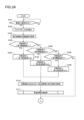
- FIGS. 2A and 2B are flow charts showing a first example of flavor source heating control executed by the control unit 116 of the aerosol generating device 100.
- the initial temperature T0 of the second heating unit 117 is acquired based on the temperature detected by the temperature sensor 112b at the start of the flavor source heating control, and when the initial temperature T0 of the second heating unit 117 is less than the threshold temperature, the target temperature Tg is set to a heating temperature higher than the warming temperature Tp, and power is supplied from the power supply unit 111 to the second heating unit 117 for a predetermined heating time.
- the start of the flavor source heating control here is not limited to the time when the flavor source heating control starts, but may include a period within a predetermined time before and after the time when the flavor source heating control starts.
- the start of the flavor source heating control may be a predetermined period from the time when the operation mode of the aerosol generating device 100 is switched to the active mode until the power supply unit 111 supplies power to the second heating unit 117 and the warming temperature Tp of the flavor source 131 is reached.
- the initial temperature T0 of the second heating section 117 at the start of execution of the flavor source heating control may be obtained at a predetermined point within the period from the point when the operating mode of the aerosol generating device 100 switches to the active mode to before power is supplied from the power supply section 111 to the second heating section 117 and the temperature Tp of the flavor source 131 is reached.
- the control unit 116 first determines whether or not the user has turned on the power (step S101). If it is determined that the user has not turned on the power (step S101: NO), the control unit 116 repeats the processing of step S101 until the user turns on the power. Then, if it is determined that the user has turned on the power (step S101: YES), the control unit 116 switches the mode in which the aerosol generating device 100 operates to the active mode (step S102). This puts the aerosol generating device 100 in a state in which it can generate aerosol.
- control unit 116 obtains the initial temperature T0 of the second heating unit 117 based on the temperature detected by the temperature sensor 112b (step S103).
- the control unit 116 determines whether the initial temperature T0 of the second heating unit 117 acquired in step S103 is less than the first threshold temperature T1 (step S104).
- the first threshold temperature T1 is, for example, 10°C. Note that the first threshold temperature T1 is not limited to 10°C and may be set to any temperature.
- the control unit 116 sets the target temperature Tg for heating the second heating unit 117 to the first heating temperature Tset1 (step S105) and proceeds to step S110.
- the first heating temperature Tset1 is a temperature higher than the insulation temperature Tp (60°C in this embodiment). In this embodiment, the first heating temperature Tset1 is 90°C. Note that the first heating temperature Tset1 is not limited to 90°C and may be set to any temperature higher than the insulation temperature Tp.
- the control unit 116 determines whether the initial temperature T0 of the second heating unit 117 acquired in step S103 is less than the second threshold temperature T2 (step S106).
- the second threshold temperature T2 is a temperature higher than the first threshold temperature T1, for example, 20°C. Note that the second threshold temperature T2 is not limited to 20°C, and may be set to any temperature higher than the first threshold temperature T1.
- the control unit 116 sets the target temperature Tg for heating the second heating unit 117 to the second heating temperature Tset2 (step S107) and proceeds to step S110.
- the second heating temperature Tset2 is higher than the insulation temperature Tp (60°C in this embodiment) and lower than the first heating temperature Tset1. In this embodiment, the second heating temperature Tset2 is 85°C. Note that the second heating temperature Tset2 is not limited to 85°C and may be set to any temperature higher than the insulation temperature Tp and lower than the first heating temperature Tset1.
- the control unit 116 determines whether the initial temperature T0 of the second heating unit 117 acquired in step S103 is less than the third threshold temperature T3 (step S108).
- the third threshold temperature T3 is a temperature higher than the second threshold temperature T2, for example, 40°C. Note that the third threshold temperature T3 is not limited to 40°C, and may be set to any temperature higher than the second threshold temperature T2.
- step S109 the control unit 116 sets the target temperature Tg for heating the second heating unit 117 to the third heating temperature Tset3 (step S109) and proceeds to step S110.
- the third heating temperature Tset3 is higher than the heat retention temperature Tp (60°C in this embodiment) and lower than the second heating temperature Tset2. In this embodiment, the third heating temperature Tset3 is 80°C. Note that the third heating temperature Tset3 is not limited to 80°C and may be set to any temperature higher than the heat retention temperature Tp and lower than the second heating temperature Tset2.
- step S108 If the initial temperature T0 of the second heating unit 117 is not less than the third threshold temperature T3 (step S108: NO), the control unit 116 proceeds to step S112, which will be described later.
- step S110 the control unit 116 supplies a predetermined amount of power to the second heating unit 117 so that the temperature of the second heating unit 117 becomes the target temperature Tg.
- the power supply control to the second heating unit 117 is realized by ON-OFF control. More specifically, when the temperature of the second heating unit 117 is below the target temperature Tg, the control unit 116 supplies power to the second heating unit 117 until the temperature of the second heating unit 117 reaches the target temperature Tg, stops the power supply to the second heating unit 117 when the temperature of the second heating unit 117 reaches the target temperature Tg and is equal to or higher than the target temperature Tg, and restarts the power supply to the second heating unit 117 when the temperature of the second heating unit 117 falls below the target temperature Tg. This makes it possible to supply power to the second heating unit 117 with simple control.
- the control unit 116 may set the voltage of the power supplied to the second heating unit 117 based on the target temperature Tg. In this case, for example, the higher the target temperature Tg, the higher the voltage of the power supplied to the second heating unit 117 is set to. This makes it possible to make the temperature of the second heating unit 117 reach the target temperature Tg in a shorter time, even if the target temperature Tg is high.
- control unit 116 may combine ON-OFF control with proportional control in controlling the power supply to the second heating unit 117.
- the duty ratio is set based on the deviation between the temperature of the second heating unit 117 and the target temperature Tg so that the larger the deviation, the larger the duty ratio, and the smaller the deviation, the smaller the duty ratio. This makes it possible to make the temperature of the second heating unit 117 reach the target temperature Tg in a shorter time even when the target temperature Tg is high, and to prevent the temperature of the second heating unit 117 from overshooting and exceeding the target temperature Tg with simple control.
- the duty ratio may be set to 50% when the temperature difference from the target temperature is less than 5°C, and to 100% when the temperature difference from the target temperature is 5°C or more.
- the power supply control to the second heating section 117 may be realized by feedback control such as PID control (PID: Proportional-Integral-Differential).
- PID control Proportional-Integral-Differential
- the control section 116 may supply power from the power supply section 111 to the second heating section 117 in the form of a power pulse by pulse width modulation (PWM) or pulse frequency modulation (PFM).
- PWM pulse width modulation
- PFM pulse frequency modulation
- the control section 116 can control the temperature of the second heating section 117 by adjusting the duty ratio of the power pulse based on the deviation between the temperature of the second heating section 117 and the target temperature Tg.
- control unit 116 when the control unit 116 detects a puffing action by the user while supplying power to the second heating unit 117 and supplies power to the first heating unit 121, the control unit 116 may temporarily set the power supplied to the second heating unit 117 to zero or to a low level. In this way, it is possible to prevent excessive current from being output from the power supply unit 111 due to the power supply to the first heating unit 121 and the second heating unit 117.
- control unit 116 proceeds to step S111 and executes a temperature rise time measurement process.
- the temperature rise time measurement process determines whether or not a predetermined temperature rise time has ended, and ends when it is determined that the predetermined temperature rise time has ended. Details of the temperature rise time measurement process will be described later.
- step S111 When the heating time measurement process in step S111 is completed, i.e., when the specified heating time has elapsed, the control unit 116 proceeds to step S112 and sets the target temperature Tg to the insulation temperature Tp.
- the manner in which the predetermined amount of power is supplied to the second heating unit 117 is the same as in step S110.
- control unit 116 judges whether or not the user has performed a power-off operation (step S114). If it is judged that the user has not performed a power-off operation (step S114: NO), it judges whether or not a predetermined time has elapsed since the user performed the most recent puffing action (step S115).
- the predetermined time is, for example, 300 [sec].
- control unit 116 determines in step S114 that the user has performed a power-off operation (step S114: YES) or determines in step S115 that a predetermined time has passed since the user performed the most recent puffing action (step S115: YES), it stops the supply of power to the second heating unit 117 (step S116).
- control unit 116 switches the operating mode of the aerosol generating device 100 to a sleep mode (step S117).
- the temperature of the second heating section 117 is maintained at the insulation temperature Tp, and the temperature of the flavor source 131 is also maintained at a temperature close to the insulation temperature Tp.
- an aerosol source with an appropriate flavor can always be supplied to the user.
- the target temperature Tg can be set to a heating temperature higher than the heat retention temperature Tp, and power can be supplied from the power supply section 111 to the second heating section 117 for a predetermined heating time, thereby causing the temperature of the second heating section 117 to reach the heat retention temperature Tp in a short time.
- This allows the temperature of the flavor source 131 to reach the heat retention temperature Tp in a shorter time, and after the aerosol generating device 100 switches to the active mode, an aerosol source imparted with an appropriate flavor can be supplied to the user in a short time.
- first threshold temperature T1 a first threshold temperature T1
- second threshold temperature T2 a third threshold temperature T3
- the target temperatures are set to the first heating temperature Tset1, the second heating temperature Tset2, and the third heating temperature Tset3 corresponding to the respective threshold temperatures, so that an appropriate target temperature can be set according to the initial temperature T0 of the second heating section 117, and the temperature of the second heating section 117 can reach the insulation temperature Tp in a short period of time.
- FIGS. 3A and 3B are flowcharts showing a second example of flavor source heating control executed by the control unit 116 of the aerosol generating device 100.
- a process is described in which the power supply stop time toff to the second heating unit 117 from the most recent power supply stop to the second heating unit 117 to the start of execution of the flavor source heating control is obtained, and if the power supply stop time toff is equal to or longer than a predetermined time, the target temperature Tg is set to a heating temperature higher than the insulation temperature Tp, and power is supplied from the power supply unit 111 to the second heating unit 117 for the predetermined heating time.
- the control unit 116 first determines whether or not the user has turned on the power (step S201). If it is determined that the user has not turned on the power (step S201: NO), the control unit 116 repeats the processing of step S201 until the user turns on the power. Then, if it is determined that the user has turned on the power (step S201: YES), the control unit 116 switches the mode in which the aerosol generating device 100 operates to the active mode (step S202). This puts the aerosol generating device 100 in a state in which it can generate aerosol.
- control unit 116 acquires the power supply stop time toff to the second heating unit 117 from the most recent power supply stop to the second heating unit 117 (step S203).
- the timing for starting counting the power supply stop time toff will be described later.
- the control unit 116 determines whether the power supply stop time toff acquired in step S203 is equal to or greater than a predetermined time ta (step S204).
- the predetermined time ta is, for example, 10 minutes. Note that the predetermined time ta is not limited to 10 minutes and may be set to any temperature. It is desirable that the predetermined time ta be a time during which there is a high probability that the temperature of the second heating unit 117 will have sufficiently dropped to or below the predetermined temperature since the most recent power supply stop to the second heating unit 117.
- the control unit 116 sets the target temperature Tg for heating the second heating unit 117 to the heating temperature Tset (step S205), and proceeds to step S206.
- the heating temperature Tset is a temperature higher than the insulation temperature Tp (60°C in this embodiment). In this embodiment, the heating temperature Tset is 80°C. Note that the heating temperature Tset is not limited to 80°C, and may be set to any temperature higher than the insulation temperature Tp.
- step S204 If the power supply stop time toff is not equal to or longer than the predetermined time ta (step S204: NO), the control unit 116 proceeds to step S208, which will be described later.
- step S206 the control unit 116 supplies a predetermined amount of power to the second heating unit 117 so that the temperature of the second heating unit 117 becomes the target temperature Tg.
- the manner in which the predetermined amount of power is supplied to the second heating unit 117 is the same as in step S110 of the first example of flavor source heating control executed by the control unit described above.
- the control unit 116 proceeds to step S207 and executes a temperature rise time measurement process.
- the temperature rise time measurement process determines whether or not a predetermined temperature rise time has ended, and ends when it is determined that the predetermined temperature rise time has ended.
- the temperature rise time measurement process is similar to the temperature rise time measurement process of the first example of flavor source heating control executed by the control unit, and details will be described later.
- step S207 When the heating time measurement process in step S207 ends, i.e., when the specified heating time ends, the control unit 116 sets the target temperature Tg to the insulation temperature Tp (step S208).
- the manner in which the predetermined amount of power is supplied to the second heating unit 117 is the same as in step S206.
- control unit 116 determines whether or not the user has performed a power-off operation (step S210). If it is determined that the user has not performed a power-off operation (step S210: NO), it determines whether or not a predetermined time has elapsed since the operation mode of the aerosol generating device 100 was switched to the active mode in step S202 (step S211).
- the predetermined time is, for example, 4 minutes and 30 seconds.
- control unit 116 determines in step S210 that the user has performed a power-off operation (step S210: YES) or determines in step S211 that a predetermined time has elapsed since the operation mode of the aerosol generating device 100 was switched to the active mode (step S211: YES), it stops the supply of power to the second heating unit 117 (step S212).
- control unit 116 resets the power supply stop time toff to 0 (step S213) and starts counting the power supply stop time toff (step S214).
- step S257 the operating mode of the aerosol generating device 100 is switched to sleep mode.
- the temperature of the second heating section 117 is maintained at the insulation temperature Tp, and the temperature of the flavor source 131 is also maintained at a temperature close to the insulation temperature Tp.
- an aerosol source with an appropriate flavor can always be supplied to the user.
- the target temperature Tg can be set to a heating temperature higher than the heat retention temperature Tp, and power can be supplied from the power supply unit 111 to the second heating unit 117 for a predetermined heating time, thereby allowing the temperature of the second heating unit 117 to reach the heat retention temperature Tp in a short time.
- the temperature rise time tset is stored in advance in the storage unit 114.
- the temperature rise time tset corresponding to the initial temperature T0 of the second heating unit may be stored in advance in the storage unit 114.
- the temperature rise time tset corresponding to the initial temperature T0 of the second heating unit is shorter as the initial temperature T0 of the second heating unit is higher.
- the temperature rise time tset may be a constant time regardless of the initial temperature T0 of the second heating unit.
- the flavor source heating control is the control flow shown in the first example of the flavor source heating control
- the temperature rise time tset corresponding to the initial temperature T0 of the second heating unit is stored in advance in the storage unit 114.
- control unit 116 first obtains the temperature rise time tset based on the initial temperature T0 of the second heating unit obtained in step S103 of the first example of the flavor source heating control described above, or in step S203 of the second example of the flavor source heating control described above (step S301).
- the control unit 116 then resets the time t to 0 (step S302) and starts counting the time t (step S303).
- step S304 determines whether the time t is equal to or greater than the heating time tset acquired in step S301 (step S304). If it is determined that the time t is not equal to or greater than the heating time tset acquired in step S301 (step S304: NO), the control unit 116 repeats the process of step S304 until the time t becomes equal to the heating time tset acquired in step S301. If it is determined that the time t is equal to or greater than the heating time tset acquired in step S301 (step S304: YES), the control unit 116 determines that the heating time has ended (step S305) and ends the heating time measurement process.
- (4-2. Second Example of Temperature Rise Time Measurement Process) 4B is a flowchart showing a second example of the temperature rise time measurement process.
- the temperature T of the second heating unit 117 is acquired based on the temperature detected by the temperature sensor 112b during the temperature rise process time measurement process.
- the temperature rise time in this example is the time required for the temperature T of the second heating unit 117 to reach the target temperature Tg.
- control unit 116 first obtains the temperature T of the second heating unit 117 based on the temperature detected by the temperature sensor 112b (step S401).
- the control unit 116 determines whether the temperature T of the second heating unit 117 is equal to or higher than the target temperature Tg (step S402). If it is determined that the temperature T of the second heating unit 117 is not equal to or higher than the target temperature Tg (step S402: NO), the control unit 116 returns to step S401 and repeats the processing of steps S401 and S402 until the temperature T of the second heating unit 117 is equal to or higher than the target temperature Tg. If it is determined that the temperature T of the second heating unit 117 is equal to or higher than the target temperature Tg (step S402: YES), the control unit 116 determines that the heating time has ended (step S403) and ends the heating time measurement processing.
- the heating time is the time it takes for the temperature T of the second heating section 117 to reach the target temperature Tg
- the heating time can be set so that the temperature T of the second heating section 117 does not exceed the target temperature Tg.
- 4C is a flowchart showing a third example of the temperature rise time measurement process.
- the temperature T of the second heating unit 117 is acquired based on the temperature detected by the temperature sensor 112b during the temperature rise process time measurement process.
- the temperature rise time in this example is the time until the temperature T of the second heating unit 117 reaches a temperature rise end temperature Te, which is a temperature lower than the target temperature Tg.
- the temperature rise end temperature Te is set to a temperature 5 [°C] lower than the target temperature Tg, for example.
- the temperature rise end temperature Te is not limited to a temperature 5 [°C] lower than the target temperature Tg, and may be set to any temperature lower than the target temperature Tg.
- control unit 116 first sets the heating end temperature Te based on the target temperature Tg (step S501).
- control unit 116 acquires the temperature T of the second heating unit 117 based on the temperature detected by the temperature sensor 112b (step S502).
- the control unit 116 determines whether the temperature T of the second heating unit 117 is equal to or higher than the end temperature Te (step S503). If it is determined that the temperature T of the second heating unit 117 is not equal to or higher than the end temperature Te (step S503: NO), the control unit 116 returns to step S502 and repeats the processing of steps S502 and S503 until the temperature T of the second heating unit 117 is equal to or higher than the end temperature Te. If it is determined that the temperature T of the second heating unit 117 is equal to or higher than the end temperature Te (step S503: YES), the control unit 116 determines that the heating time has ended (step S504) and ends the heating time measurement processing.
- the heating time can be set to more reliably prevent the temperature T of the second heating section 117 from exceeding the target temperature Tg.
- FIG. 4D is a flowchart showing a fourth example of the temperature rise time measurement process.
- the temperature T of the second heating unit 117 is acquired based on the detected temperature of the temperature sensor 112b during the temperature rise process time measurement process.
- the temperature rise time in this example is the time from when the temperature T of the second heating unit 117 reaches the target temperature Tg until a preset fixed time tc has elapsed.
- the fixed time tc is stored in the storage unit 114, and is, for example, 3 seconds. Note that the fixed time tc is not limited to 3 seconds, and may be set to any time.
- the temperature rise time may also be the time from when the temperature T of the second heating unit 117 reaches a predetermined temperature lower than the target temperature Tg (for example, a temperature similar to the temperature rise end temperature Te in the third example of the temperature rise time measurement process) until a preset fixed time tc has elapsed.
- a predetermined temperature lower than the target temperature Tg for example, a temperature similar to the temperature rise end temperature Te in the third example of the temperature rise time measurement process
- control unit 116 first obtains the temperature T of the second heating unit 117 based on the temperature detected by the temperature sensor 112b (step S601).
- control unit 116 determines whether the temperature T of the second heating unit 117 is equal to or higher than the target temperature Tg (step S602). If it is determined that the temperature T of the second heating unit 117 is not equal to or higher than the target temperature Tg (step S602: NO), the control unit 116 returns to step S601 and repeats the processing of steps S601 and S602 until the temperature T of the second heating unit 117 is equal to or higher than the target temperature Tg.
- control unit 116 determines that the temperature T of the second heating unit 117 is equal to or higher than the target temperature Tg (step S602: YES), it resets the time t to 0 (step S603) and starts counting the time t (step S604).
- step S605 determines whether the time t is equal to or greater than the certain time tc stored in the memory unit 114 (step S605). If it is determined that the time t is not equal to or greater than the certain time tc (step S605: NO), the process of step S605 is repeated until the time t becomes equal to or greater than the certain time tc. If it is determined that the time t is equal to or greater than the certain time tc (step S605: YES), the control unit 116 determines that the heating time has ended (step S606), and ends the heating time measurement process.
- the heating time can be set more stably.
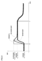
- FIG. 5 is a diagram showing an example of temperature transitions of the second heating unit 117 and the flavor source 131 and transitions of the target temperature Tg during flavor source heating control, where the horizontal axis represents time and the vertical axis represents temperature.
- the flavor source heating control is the control flow shown in the first example of flavor source heating control
- the initial temperature T0 of the second heating unit 117 is equal to or higher than the second threshold temperature T2 and lower than the third threshold temperature T3, for example, the initial temperature T0 is 25°C
- the temperature rise time measurement process is the control flow shown in the second example of the temperature rise time measurement process.
- a thin solid line indicates the transition of the target temperature Tg in the flavor source heating control
- a thick dashed line indicates the transition of the temperature of the second heating unit 117
- a thick solid line indicates the transition of the temperature of the flavor source 131.
- the operation mode of the aerosol generating device 100 is switched to the active mode at time t0. Then, the flavor source heating control is started with the operation mode of the aerosol generating device 100 being switched to the active mode.
- the target temperature Tg of the second heating section 117 is set to the third heating temperature Tset3 (80°C in this example), and power is supplied to the second heating section 117 so that the temperature of the second heating section 117 becomes the third heating temperature Tset3.
- the target temperature Tg is set to the third heating temperature Tset3, which is a temperature higher than the heat retention temperature Tp, the temperature of the second heating section 117 can reach the heat retention temperature Tp in a shorter time than when the target temperature Tg is set to the heat retention temperature Tp.
- the flavor source 131 is heated by the heat generated by the second heating section 117, so it heats up more slowly and later than the second heating section 117.
- the heating time ends and the target temperature Tg is changed to the insulation temperature Tp (60°C in this example), and power is supplied so that the temperature of the second heating section 117 becomes the insulation temperature Tp.
- the temperature rise time is set so that the temperature of the flavor source 131 is close to the warming temperature Tp but does not exceed the warming temperature Tp when the temperature rise time is completed.
- the temperature of the second heating section 117 reaches the third heating temperature Tset3
- the temperature of the second heating section 117 is higher than the heat retention temperature Tp, so the power supply to the second heating section 117 is temporarily halted until the temperature of the second heating section 117 drops to the heat retention temperature Tp. Then, when the temperature of the second heating section 117 reaches the heat retention temperature Tp, power is supplied to the second heating section 117 so that the temperature of the second heating section 117 is maintained at the heat retention temperature Tp.
- the aerosol generating device 100B includes a power supply unit 110B including a power supply unit 111B, a sensor unit 112B, a notification unit 113B, a memory unit 114B, a communication unit 115B, a control unit 116B, a heating unit 121B, a storage unit 140, and a heat insulating unit 144.
- the temperature sensor 112b is disposed near the heating unit 121B.
- the vicinity of the heating unit 121B is a position where at least the temperature sensor 112b can detect a temperature change in the heating unit 121B.
- the vicinity of the heating unit 121B may be a position adjacent to the heating unit 121B or the storage unit 140.
- Each of the power supply unit 111B, the sensor unit 112B, the notification unit 113B, the memory unit 114B, the communication unit 115B, and the control unit 116B is substantially identical to the corresponding components included in the aerosol generating device 100 described above.
- the storage section 140 has an internal space 141 and holds the stick-shaped substrate 150 while storing a part of the stick-shaped substrate 150 in the internal space 141.
- the storage section 140 has an opening 142 that connects the internal space 141 to the outside, and stores the stick-shaped substrate 150 inserted into the internal space 141 through the opening 142.
- the storage section 140 is a cylindrical body with the opening 142 and the bottom 143 as the bottom surface, and defines a columnar internal space 141.
- An air flow path that supplies air to the internal space 141 is connected to the storage section 140.
- An air inlet hole which is an air inlet to the air flow path, is arranged, for example, on the side of the aerosol generating device 100.
- An air outlet hole which is an air outlet from the air flow path to the internal space 141, is arranged, for example, on the bottom 143.
- the stick-type substrate 150 includes a substrate portion 151 and a mouthpiece portion 152.
- the substrate portion 151 includes an aerosol source.
- the aerosol source includes a tobacco-derived or non-tobacco-derived flavor source.
- the aerosol source may include a drug.
- the aerosol source may be, for example, a liquid such as a polyhydric alcohol such as glycerin and propylene glycol, and water, including a tobacco-derived or non-tobacco-derived flavor source, or may be a solid including a tobacco-derived or non-tobacco-derived flavor source.
- the stick-type substrate 150 When the stick-type substrate 150 is held in the storage portion 140, at least a portion of the substrate portion 151 is stored in the internal space 141, and at least a portion of the mouthpiece portion 152 protrudes from the opening 142.
- the suction mouth portion 152 protruding from the opening 142 in their mouth and inhales air flows into the internal space 141 via an air flow path (not shown) and reaches the user's mouth together with the aerosol generated from the base portion 151.
- the heating section 121B is configured in a film shape and is arranged to cover the outer periphery of the storage section 140.
- the heating section 121B generates heat, the substrate section 151 of the stick-shaped substrate 150 is heated from the outer periphery, and an aerosol is generated.
- the insulating section 144 prevents heat transfer from the heating section 121B to other components.
- the insulating section 144 is made of a vacuum insulating material or an aerogel insulating material.
- the configuration of the aerosol generating device 100B is not limited to the above, and various configurations such as those exemplified below are possible.
- the heating section that heats the flavor source is heating section 121B.
- the flavor source is included in substrate section 151 of stick-shaped substrate 150.
- the aerosol generating device 100B can also execute the flavor source heating control described above, similar to the aerosol generating device 100.
- the flavor source heating control is started when the operation mode of the aerosol generating device 100 is switched to the active mode, but it may be started when a heating start instruction is input.
- the heating start instruction may be, for example, detection of a puffing action by a user, operation of an input device such as an operation button or switch by a user, or detection of insertion of the stick-shaped substrate 150 in the other configuration examples of the aerosol generating device described above.
- the acquisition of the initial temperature T0 of the second heating unit 117 at the start of the flavor source heating control may be performed, for example, at a predetermined time within a predetermined period from the time when the heating start instruction is input until the second heating unit 117 is supplied with power from the power supply unit 111 and reaches the insulation temperature Tp of the flavor source 131.
- the first threshold temperature T1 when there is one threshold temperature, there is also one target temperature Tg. Therefore, in the first example of flavor source heating control, when there is one threshold temperature, the heating end temperature Te is a predetermined value that is stored in advance, and the above-mentioned step S501 may be a process of acquiring the stored predetermined value of the heating end temperature Te.
- the control described in the above-mentioned embodiment can be realized by executing a prepared program on a computer (processor).
- This program is stored in a computer-readable storage medium and is executed by reading it from the storage medium.
- This program may be provided in a form stored in a non-transitory storage medium such as a flash memory (e.g., storage unit 114, 114B), or provided via a network such as the Internet.
- the computer that executes this program can be, for example, one included in the aerosol generating device 100, 100B (e.g., the CPU of the control unit 116), but is not limited to this, and may also be one included in another device (e.g., a smartphone or a server) that can communicate with the aerosol generating device 100, 100B.
- a power source capable of supplying power to a heating unit (second heating unit 117, heating unit 121B) that heats a flavor source (flavor source 131, base material unit 151);
- a control unit controls the power supplied to the heating unit;
- a power supply unit power supply unit 110, 110B) of an aerosol generating device (aerosol generating device 100, 100B) comprising:
- the control unit is A flavor source heating control is executed to set a target temperature (target temperature Tg) of the temperature of the heating unit so that the temperature of the flavor source becomes a predetermined warming temperature (warming temperature Tp), and to supply power from the power source to the heating unit so that the temperature of the heating unit becomes the target temperature,
- An initial temperature (initial temperature T0) of the heating unit at the start of execution of the flavor source heating control is acquired;
- a threshold temperature a first threshold temperature T1, a second threshold temperature T2, or a third threshold temperature
- the temperature of the heating section can reach the warming temperature in a short time. This allows the temperature of the flavor source to reach the warming temperature in a shorter time, and an aerosol source with an appropriate flavor can be supplied to the user.
- a power supply unit for the aerosol generating device In the flavor source heating control, the control unit a first threshold temperature (first threshold temperature T1) and a second threshold temperature (second threshold temperature T2) that is higher than the first threshold temperature; When the initial temperature of the heating unit is less than the first threshold temperature, The target temperature is set to a first heating temperature (first heating temperature Tset1) higher than the warming temperature, and power is supplied from the power source to the heating unit for a predetermined heating time; When the initial temperature of the heating unit is less than the second threshold temperature, The target temperature is set to a second heating temperature (second heating temperature Tset2) that is higher than the warming temperature and lower than the first heating temperature, and power is supplied from the power source to the heating unit for a predetermined heating time. Power supply unit for the aerosol generator.
- the target temperature is set to the first heating temperature and the second heating temperature corresponding to the respective threshold temperatures, so that an appropriate target temperature can be set according to the initial temperature of the heating section, and the temperature of the heating section can be made to reach the insulation temperature in a short period of time.
- a power supply unit for the aerosol generating device In the flavor source heating control, the control unit having three or more different threshold temperatures; The target temperatures are set to the heating temperatures corresponding to the respective threshold temperatures. Power supply unit for the aerosol generator.
- an appropriate target temperature can be set according to the initial temperature of the heating section, and the temperature of the heating section can reach the insulation temperature in a short period of time.
- a power source capable of supplying power to a heating unit (second heating unit 117, heating unit 121B) that heats the flavor source (flavor source 131, base material unit 151);
- a control unit controls the power supplied to the heating unit;
- a power supply unit power supply unit 110, 110B) of an aerosol generating device (aerosol generating device 100, 100B) comprising:
- the control unit is A flavor source heating control is executed to set a target temperature (target temperature Tg) of the temperature of the heating unit so that the temperature of the flavor source becomes a predetermined warming temperature (warming temperature Tp), and to supply power from the power source to the heating unit so that the temperature of the heating unit becomes the target temperature,
- a power supply stop time power supply stop time toff) to the heating unit is acquired from the most recent power supply stop to the heating unit to the start of execution of the flavor source heating control; If the power supply stop time is equal to or longer than a predetermined
- the temperature of the heating section can reach the warming temperature in a short time. This allows the temperature of the flavor source to reach the warming temperature in a shorter time, and an aerosol source with an appropriate flavor can be supplied to the user.
- a power supply unit for the aerosol generating device according to any one of (1) to (4),
- the control unit is
- the aerosol generating device has a plurality of operating modes including an active mode in which the aerosol generating device maintains a state in which the aerosol generating device can generate aerosol, and a sleep mode in which the aerosol generating device operates with less power consumption than the active mode, When the mode is switched to the active mode, the flavor source heating control is started.
- Power supply unit for the aerosol generator is the plurality of operating modes including an active mode in which the aerosol generating device maintains a state in which the aerosol generating device can generate aerosol, and a sleep mode in which the aerosol generating device operates with less power consumption than the active mode, When the mode is switched to the active mode, the flavor source heating control is started. Power supply unit for the aerosol generator.
- an aerosol source imparted with an appropriate flavor can be supplied to the user in a short time.
- a power supply unit for the aerosol generating device In the flavor source heating control, the control unit When the temperature of the heating unit is lower than the target temperature, power is supplied to the heating unit, and when the temperature of the heating unit is equal to or higher than the target temperature, power supply to the heating unit is stopped. Power supply to the heating unit is performed by ON-OFF control. Power supply unit for the aerosol generator.
- a power supply unit for the aerosol generating device In the flavor source heating control, the control unit The ON-OFF control is combined with proportional control in which a duty ratio is set based on a deviation between the temperature of the heating unit and the target temperature, and power is supplied to the heating unit. Power supply unit for the aerosol generator.
- the temperature of the heating section can reach the target temperature in a shorter time, and simple control can be used to prevent the temperature of the heating section from overshooting and exceeding the target temperature.
- a power supply unit for the aerosol generating device according to any one of (1) to (7), Further provided with a heating section temperature detection element (temperature sensor 112b), The temperature of the heating part is acquired based on the detected temperature of the heating part temperature detection element. Power supply unit for the aerosol generator.
- the temperature of the heating section can be obtained with a simple configuration.
- a power supply unit for the aerosol generating device according to any one of (1) to (8), The temperature rise time is preset. Power supply unit for the aerosol generator.
- a power supply unit for the aerosol generating device according to any one of (1) to (8),
- the temperature rise time is the time it takes for the temperature of the heating unit to reach the target temperature.
- Power supply unit for the aerosol generator is the power supply unit for the aerosol generator.
- the heating time is the time it takes for the temperature of the heating part to reach the target temperature, so that the heating time can be set so that the temperature of the heating part does not exceed the target temperature.
- a power supply unit for the aerosol generating device according to any one of (1) to (8),
- the temperature rise time is a time until the temperature of the heating part reaches a temperature rise end temperature (temperature rise end temperature Te) which is a temperature lower than the target temperature.
- Power supply unit for the aerosol generator is a temperature rise end temperature (temperature rise end temperature Te) which is a temperature lower than the target temperature.
- the heating time is the time it takes for the temperature of the heating part to reach the heating end temperature, which is a temperature lower than the target temperature, so that the heating time can be set so as to more reliably prevent the temperature of the heating part from exceeding the target temperature.
- a power supply unit for the aerosol generating device according to any one of (1) to (8),
- the temperature rise time is a time from when the temperature of the heating unit reaches the target temperature or a predetermined temperature lower than the target temperature until a preset certain time has elapsed.
- Power supply unit for the aerosol generator is
- the heating time is the time from when the temperature of the heating part reaches the target temperature or a predetermined temperature lower than the target temperature until a preset fixed time has elapsed. This makes it possible to eliminate unintended overshoots in the temperature of the heating part and erroneous detection of the temperature of the heating part due to noise, etc., and allows the heating time to be set more stably.
- a heating section (second heating section 117, heating section 121B) for heating the flavor source (flavor source 131, base material section 151);
- a power source (power source unit 111, 111B) capable of supplying power to the heating unit;
- a control unit (control unit 116, 116B) that controls the power supplied to the heating unit;
- An aerosol generating apparatus (aerosol generating apparatus 100, 100B) comprising:
- the control unit is A flavor source heating control is executed to set a target temperature (target temperature Tg) of the temperature of the heating unit so that the temperature of the flavor source becomes a predetermined warming temperature (warming temperature Tp), and to supply power from the power source to the heating unit so that the temperature of the heating unit becomes the target temperature,
- An initial temperature (initial temperature T0) of the heating unit at the start of execution of the flavor source heating control is acquired;
- a threshold temperature a first threshold temperature T1, a second threshold temperature T2, or a third threshold temperature T3
- the temperature of the heating section can reach the warming temperature in a short time. This allows the temperature of the flavor source to reach the warming temperature in a shorter time, and an aerosol source with an appropriate flavor can be supplied to the user.
Landscapes
- Charge And Discharge Circuits For Batteries Or The Like (AREA)
- Catching Or Destruction (AREA)
Priority Applications (3)
| Application Number | Priority Date | Filing Date | Title |
|---|---|---|---|
| CN202380093412.1A CN120603511A (zh) | 2023-02-13 | 2023-02-13 | 用于气溶胶产生装置的供电单元和气溶胶产生装置 |
| PCT/JP2023/004837 WO2024171266A1 (ja) | 2023-02-13 | 2023-02-13 | エアロゾル生成装置の電源ユニット、及び、エアロゾル生成装置 |
| JP2025500442A JPWO2024171266A1 (https=) | 2023-02-13 | 2023-02-13 |
Applications Claiming Priority (1)
| Application Number | Priority Date | Filing Date | Title |
|---|---|---|---|
| PCT/JP2023/004837 WO2024171266A1 (ja) | 2023-02-13 | 2023-02-13 | エアロゾル生成装置の電源ユニット、及び、エアロゾル生成装置 |
Publications (1)
| Publication Number | Publication Date |
|---|---|
| WO2024171266A1 true WO2024171266A1 (ja) | 2024-08-22 |
Family
ID=92420933
Family Applications (1)
| Application Number | Title | Priority Date | Filing Date |
|---|---|---|---|
| PCT/JP2023/004837 Ceased WO2024171266A1 (ja) | 2023-02-13 | 2023-02-13 | エアロゾル生成装置の電源ユニット、及び、エアロゾル生成装置 |
Country Status (3)
| Country | Link |
|---|---|
| JP (1) | JPWO2024171266A1 (https=) |
| CN (1) | CN120603511A (https=) |
| WO (1) | WO2024171266A1 (https=) |
Citations (4)
| Publication number | Priority date | Publication date | Assignee | Title |
|---|---|---|---|---|
| WO2020044385A1 (ja) * | 2018-08-27 | 2020-03-05 | 日本たばこ産業株式会社 | 香味成分送達装置 |
| US20200146361A1 (en) * | 2018-11-09 | 2020-05-14 | Pax Labs, Inc. | Vaporizing related data protocols |
| JP2022057850A (ja) * | 2020-09-30 | 2022-04-11 | 日本たばこ産業株式会社 | エアロゾル生成装置の電源ユニット、エアロゾル生成装置 |
| WO2022209528A1 (ja) * | 2021-04-01 | 2022-10-06 | 日本たばこ産業株式会社 | エアロゾル生成装置 |
-
2023
- 2023-02-13 JP JP2025500442A patent/JPWO2024171266A1/ja active Pending
- 2023-02-13 WO PCT/JP2023/004837 patent/WO2024171266A1/ja not_active Ceased
- 2023-02-13 CN CN202380093412.1A patent/CN120603511A/zh active Pending
Patent Citations (4)
| Publication number | Priority date | Publication date | Assignee | Title |
|---|---|---|---|---|
| WO2020044385A1 (ja) * | 2018-08-27 | 2020-03-05 | 日本たばこ産業株式会社 | 香味成分送達装置 |
| US20200146361A1 (en) * | 2018-11-09 | 2020-05-14 | Pax Labs, Inc. | Vaporizing related data protocols |
| JP2022057850A (ja) * | 2020-09-30 | 2022-04-11 | 日本たばこ産業株式会社 | エアロゾル生成装置の電源ユニット、エアロゾル生成装置 |
| WO2022209528A1 (ja) * | 2021-04-01 | 2022-10-06 | 日本たばこ産業株式会社 | エアロゾル生成装置 |
Also Published As
| Publication number | Publication date |
|---|---|
| JPWO2024171266A1 (https=) | 2024-08-22 |
| CN120603511A (zh) | 2025-09-05 |
Similar Documents
| Publication | Publication Date | Title |
|---|---|---|
| JP7481444B2 (ja) | 吸引装置、制御方法、及びプログラム | |
| JP7663703B2 (ja) | 吸引装置、基材、及び制御方法 | |
| JP2025175009A (ja) | エアロゾル生成システム、制御方法、及びプログラム | |
| TW202224583A (zh) | 控制方法、吸嚐裝置、終端裝置及程式 | |
| WO2023112247A1 (ja) | エアロゾル生成システム、及び端末装置 | |
| JP7720476B2 (ja) | エアロゾル生成システム、制御方法、及びプログラム | |
| WO2024171266A1 (ja) | エアロゾル生成装置の電源ユニット、及び、エアロゾル生成装置 | |
| US20230371602A1 (en) | Inhalation device, base material, control method, and non-transitory computer readable medium | |
| JP7705956B2 (ja) | 吸引装置 | |
| CN118354689A (zh) | 吸引装置 | |
| WO2023181282A1 (ja) | エアロゾル生成システム、制御方法、及びプログラム | |
| EP4635344A1 (en) | Power supply unit for inhalation device, control method, and control program | |
| EP4427615A1 (en) | Aerosol generation system, control method, and program | |
| JP7646066B2 (ja) | 誘導加熱システム、制御方法、及びプログラム | |
| WO2024127662A1 (ja) | 吸引装置、制御方法、及び制御プログラム | |
| WO2024127658A1 (ja) | 吸引装置の電源ユニット、制御方法、及び制御プログラム | |
| EP4559336A1 (en) | Aerosol generation system, control method, and program | |
| EP4563024A1 (en) | Aerosol generation system, control method, and program | |
| JP7688774B2 (ja) | 誘導加熱システム、制御方法、及びプログラム | |
| JP7813379B2 (ja) | エアロゾル生成システム、制御方法及びプログラム | |
| EP4613138A1 (en) | Information processing device, inhalation system, and information presentation method | |
| WO2026018403A1 (ja) | 吸引装置および方法 | |
| WO2022190211A1 (ja) | 吸引装置、及びプログラム | |
| WO2025126305A1 (ja) | 吸引装置および方法 | |
| CN120769712A (zh) | 气溶胶产生系统、控制方法和非暂时性存储介质 |
Legal Events
| Date | Code | Title | Description |
|---|---|---|---|
| 121 | Ep: the epo has been informed by wipo that ep was designated in this application |
Ref document number: 23922606 Country of ref document: EP Kind code of ref document: A1 |
|
| WWE | Wipo information: entry into national phase |
Ref document number: 202380093412.1 Country of ref document: CN |
|
| ENP | Entry into the national phase |
Ref document number: 2025500442 Country of ref document: JP Kind code of ref document: A |
|
| WWE | Wipo information: entry into national phase |
Ref document number: 2025500442 Country of ref document: JP |
|
| WWP | Wipo information: published in national office |
Ref document number: 202380093412.1 Country of ref document: CN |
|
| NENP | Non-entry into the national phase |
Ref country code: DE |
|
| 122 | Ep: pct application non-entry in european phase |
Ref document number: 23922606 Country of ref document: EP Kind code of ref document: A1 |