WO2024166908A1 - 活物質、固体電解質、電極合剤並びに電池 - Google Patents
活物質、固体電解質、電極合剤並びに電池 Download PDFInfo
- Publication number
- WO2024166908A1 WO2024166908A1 PCT/JP2024/003905 JP2024003905W WO2024166908A1 WO 2024166908 A1 WO2024166908 A1 WO 2024166908A1 JP 2024003905 W JP2024003905 W JP 2024003905W WO 2024166908 A1 WO2024166908 A1 WO 2024166908A1
- Authority
- WO
- WIPO (PCT)
- Prior art keywords
- iron
- solid electrolyte
- active material
- less
- compound
- Prior art date
- Legal status (The legal status is an assumption and is not a legal conclusion. Google has not performed a legal analysis and makes no representation as to the accuracy of the status listed.)
- Ceased
Links
Images







Classifications
-
- H—ELECTRICITY
- H01—ELECTRIC ELEMENTS
- H01B—CABLES; CONDUCTORS; INSULATORS; SELECTION OF MATERIALS FOR THEIR CONDUCTIVE, INSULATING OR DIELECTRIC PROPERTIES
- H01B1/00—Conductors or conductive bodies characterised by the conductive materials; Selection of materials as conductors
- H01B1/06—Conductors or conductive bodies characterised by the conductive materials; Selection of materials as conductors mainly consisting of other non-metallic substances
-
- H—ELECTRICITY
- H01—ELECTRIC ELEMENTS
- H01M—PROCESSES OR MEANS, e.g. BATTERIES, FOR THE DIRECT CONVERSION OF CHEMICAL ENERGY INTO ELECTRICAL ENERGY
- H01M4/00—Electrodes
- H01M4/02—Electrodes composed of, or comprising, active material
- H01M4/36—Selection of substances as active materials, active masses, active liquids
- H01M4/362—Composites
- H01M4/364—Composites as mixtures
-
- H—ELECTRICITY
- H01—ELECTRIC ELEMENTS
- H01M—PROCESSES OR MEANS, e.g. BATTERIES, FOR THE DIRECT CONVERSION OF CHEMICAL ENERGY INTO ELECTRICAL ENERGY
- H01M10/00—Secondary cells; Manufacture thereof
- H01M10/05—Accumulators with non-aqueous electrolyte
- H01M10/052—Li-accumulators
-
- H—ELECTRICITY
- H01—ELECTRIC ELEMENTS
- H01M—PROCESSES OR MEANS, e.g. BATTERIES, FOR THE DIRECT CONVERSION OF CHEMICAL ENERGY INTO ELECTRICAL ENERGY
- H01M10/00—Secondary cells; Manufacture thereof
- H01M10/05—Accumulators with non-aqueous electrolyte
- H01M10/056—Accumulators with non-aqueous electrolyte characterised by the materials used as electrolytes, e.g. mixed inorganic/organic electrolytes
- H01M10/0561—Accumulators with non-aqueous electrolyte characterised by the materials used as electrolytes, e.g. mixed inorganic/organic electrolytes the electrolyte being constituted of inorganic materials only
- H01M10/0562—Solid materials
-
- H—ELECTRICITY
- H01—ELECTRIC ELEMENTS
- H01M—PROCESSES OR MEANS, e.g. BATTERIES, FOR THE DIRECT CONVERSION OF CHEMICAL ENERGY INTO ELECTRICAL ENERGY
- H01M10/00—Secondary cells; Manufacture thereof
- H01M10/05—Accumulators with non-aqueous electrolyte
- H01M10/058—Construction or manufacture
- H01M10/0585—Construction or manufacture of accumulators having only flat construction elements, i.e. flat positive electrodes, flat negative electrodes and flat separators
-
- H—ELECTRICITY
- H01—ELECTRIC ELEMENTS
- H01M—PROCESSES OR MEANS, e.g. BATTERIES, FOR THE DIRECT CONVERSION OF CHEMICAL ENERGY INTO ELECTRICAL ENERGY
- H01M4/00—Electrodes
- H01M4/02—Electrodes composed of, or comprising, active material
- H01M4/13—Electrodes for accumulators with non-aqueous electrolyte, e.g. for lithium-accumulators; Processes of manufacture thereof
- H01M4/136—Electrodes based on inorganic compounds other than oxides or hydroxides, e.g. sulfides, selenides, tellurides, halogenides or LiCoFy
-
- H—ELECTRICITY
- H01—ELECTRIC ELEMENTS
- H01M—PROCESSES OR MEANS, e.g. BATTERIES, FOR THE DIRECT CONVERSION OF CHEMICAL ENERGY INTO ELECTRICAL ENERGY
- H01M4/00—Electrodes
- H01M4/02—Electrodes composed of, or comprising, active material
- H01M4/36—Selection of substances as active materials, active masses, active liquids
- H01M4/58—Selection of substances as active materials, active masses, active liquids of inorganic compounds other than oxides or hydroxides, e.g. sulfides, selenides, tellurides, halogenides or LiCoFy; of polyanionic structures, e.g. phosphates, silicates or borates
-
- H—ELECTRICITY
- H01—ELECTRIC ELEMENTS
- H01M—PROCESSES OR MEANS, e.g. BATTERIES, FOR THE DIRECT CONVERSION OF CHEMICAL ENERGY INTO ELECTRICAL ENERGY
- H01M4/00—Electrodes
- H01M4/02—Electrodes composed of, or comprising, active material
- H01M4/36—Selection of substances as active materials, active masses, active liquids
- H01M4/58—Selection of substances as active materials, active masses, active liquids of inorganic compounds other than oxides or hydroxides, e.g. sulfides, selenides, tellurides, halogenides or LiCoFy; of polyanionic structures, e.g. phosphates, silicates or borates
- H01M4/581—Chalcogenides or intercalation compounds thereof
- H01M4/5815—Sulfides
-
- H—ELECTRICITY
- H01—ELECTRIC ELEMENTS
- H01M—PROCESSES OR MEANS, e.g. BATTERIES, FOR THE DIRECT CONVERSION OF CHEMICAL ENERGY INTO ELECTRICAL ENERGY
- H01M4/00—Electrodes
- H01M4/02—Electrodes composed of, or comprising, active material
- H01M4/62—Selection of inactive substances as ingredients for active masses, e.g. binders, fillers
- H01M4/624—Electric conductive fillers
-
- H—ELECTRICITY
- H01—ELECTRIC ELEMENTS
- H01M—PROCESSES OR MEANS, e.g. BATTERIES, FOR THE DIRECT CONVERSION OF CHEMICAL ENERGY INTO ELECTRICAL ENERGY
- H01M4/00—Electrodes
- H01M4/02—Electrodes composed of, or comprising, active material
- H01M4/62—Selection of inactive substances as ingredients for active masses, e.g. binders, fillers
- H01M4/624—Electric conductive fillers
- H01M4/625—Carbon or graphite
-
- H—ELECTRICITY
- H01—ELECTRIC ELEMENTS
- H01M—PROCESSES OR MEANS, e.g. BATTERIES, FOR THE DIRECT CONVERSION OF CHEMICAL ENERGY INTO ELECTRICAL ENERGY
- H01M4/00—Electrodes
- H01M4/02—Electrodes composed of, or comprising, active material
- H01M2004/026—Electrodes composed of, or comprising, active material characterised by the polarity
- H01M2004/028—Positive electrodes
-
- H—ELECTRICITY
- H01—ELECTRIC ELEMENTS
- H01M—PROCESSES OR MEANS, e.g. BATTERIES, FOR THE DIRECT CONVERSION OF CHEMICAL ENERGY INTO ELECTRICAL ENERGY
- H01M2300/00—Electrolytes
- H01M2300/0017—Non-aqueous electrolytes
- H01M2300/0065—Solid electrolytes
- H01M2300/0068—Solid electrolytes inorganic
-
- Y—GENERAL TAGGING OF NEW TECHNOLOGICAL DEVELOPMENTS; GENERAL TAGGING OF CROSS-SECTIONAL TECHNOLOGIES SPANNING OVER SEVERAL SECTIONS OF THE IPC; TECHNICAL SUBJECTS COVERED BY FORMER USPC CROSS-REFERENCE ART COLLECTIONS [XRACs] AND DIGESTS
- Y02—TECHNOLOGIES OR APPLICATIONS FOR MITIGATION OR ADAPTATION AGAINST CLIMATE CHANGE
- Y02E—REDUCTION OF GREENHOUSE GAS [GHG] EMISSIONS, RELATED TO ENERGY GENERATION, TRANSMISSION OR DISTRIBUTION
- Y02E60/00—Enabling technologies; Technologies with a potential or indirect contribution to GHG emissions mitigation
- Y02E60/10—Energy storage using batteries
Definitions
- the present invention relates to an active material and a solid electrolyte.
- the present invention also relates to an electrode mixture containing the active material and a battery containing the active material and a solid electrolyte.
- the active material produced according to this method makes it possible to improve the performance of lithium-ion batteries more than ever before.
- this active material is also economically advantageous because it does not require rare metals such as cobalt.
- An object of the present invention is to provide an active material and a solid electrolyte that can improve the performance of lithium ion batteries.
- the inventors discovered that by controlling the amount of a specific element, specifically iron (Fe), that is blended into the sulfide used in the active material proposed in the above-mentioned Patent Document 1, and then combining the resulting sulfide with a conductive material to form an active material, or by using the sulfide as a solid electrolyte, it is possible to improve battery performance, such as capacity and rate characteristics, more than ever before.
- a specific element specifically iron (Fe)
- the present invention has been made based on the above findings, and includes a compound and a conductive material,
- the compound contains lithium (Li), sulfur (S), phosphorus (P), iron (Fe) and a halogen (X),
- the present invention provides an active material in which the molar ratio of the lithium (Li) element to the sum of the iron (Fe) element and the phosphorus (P) element, the molar ratio of the halogen (X) element to the sum of the iron (Fe) element and the phosphorus (P) element, the sum of the moles of the halogen (X) element and the iron (Fe) element, and the molar ratio of the iron (Fe) element to the sum of the iron (Fe) element and the phosphorus (P) element satisfy the
- the present invention also includes a compound containing lithium (Li), sulfur (S), phosphorus (P), iron (Fe) and a halogen (X),
- the present invention provides a solid electrolyte in which a molar ratio of the lithium (Li) element to the sum of the iron (Fe) element and the phosphorus (P) element, a molar ratio of the halogen (X) element to the sum of the iron (Fe) element and the phosphorus (P) element, a sum of the moles of the halogen (X) element and the iron (Fe) element, and a molar ratio of the iron (Fe) element to the sum of the iron (Fe) element and the phosphorus (P) element satisfy the following relational expressions: (1) 5.8 ⁇ Li/(Fe+P) ⁇ 10.0 (2) 0.1 ⁇ X/(Fe+P) ⁇ 1.4 (3) 0.2 ⁇ X+Fe ⁇ 2.0 (4) 0.0 ⁇ Fe/(Fe+P) ⁇ 1.0
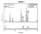
- FIG. 1 shows the X-ray diffraction patterns of the active material and solid electrolyte produced in Example 1.
- FIG. 2 shows the X-ray diffraction patterns of the active material and solid electrolyte produced in Example 2.
- FIG. 3 shows the X-ray diffraction patterns of the active material and solid electrolyte produced in Example 3.
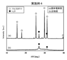
- FIG. 4 shows the X-ray diffraction patterns of the active material and solid electrolyte produced in Example 4.
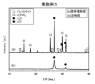
- FIG. 5 shows the X-ray diffraction patterns of the active material and solid electrolyte produced in Example 5.
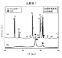
- FIG. 6 shows the X-ray diffraction patterns of the active material and solid electrolyte produced in Comparative Example 1.
- FIG. 1 shows the X-ray diffraction patterns of the active material and solid electrolyte produced in Example 1.
- FIG. 2 shows the X-ray diffraction patterns of the active material and solid electrolyte produced in Example 2.
- FIG. 3 shows the X-ray dif
- FIG. 7 shows the X-ray diffraction patterns of the active material and solid electrolyte produced in Comparative Example 2.
- FIG. 8 shows the X-ray diffraction patterns of the active material and solid electrolyte produced in Comparative Example 3.
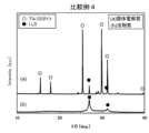
- FIG. 9 shows the X-ray diffraction patterns of the active material and solid electrolyte produced in Comparative Example 4.
- FIG. 10 shows the X-ray diffraction patterns of the active material and solid electrolyte produced in Comparative Example 5.
- FIG. 11 shows charge/discharge curves of a battery using the active material produced in Example 1 as the positive electrode active material.
- FIG. 12 shows charge/discharge curves of a battery using the active material produced in Example 5 as the positive electrode active material.
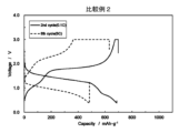
- FIG. 13 shows charge/discharge curves of a battery using the active material produced in Comparative Example 2 as the positive electrode active material.
- FIG. 14 shows charge/discharge curves of a battery using the active material produced in Comparative Example 4 as the positive
- the active material of the present invention contains particles of a specific compound and particles of a conductive material.
- the active material of the present invention preferably contains particles of a specific compound and particles composed of a conductive material that is dispersed on the surface and/or inside the particles of the compound and imparts electronic conductivity to the compound.
- a battery equipped with the active material of the present invention having such a structure has a high initial discharge capacity and is able to maintain a high capacity even when discharged at a high rate.
- the compound and the conductive material are composited.
- the “composite” include a case where particles of the conductive material are inseparably dispersed on the surface and/or inside of the compound particles, and a case where the compound particles and the conductive material particles are chemically reacted and bonded.
- the compound and the conductive material are inseparably composited.
- the term "inseparably dispersed” refers to a state in which, for example, when the active material of the present invention is observed with a scanning electron microscope (SEM-EDS) equipped with an energy dispersive X-ray spectrometer and the constituent elements of the compound (e.g., sulfur element) and the constituent elements of the conductive material are mapped, it can be confirmed that the constituent elements of the compound (e.g., sulfur element) and the constituent elements of the conductive material are present so as to overlap.
- SEM-EDS scanning electron microscope
- the constituent elements of the compound e.g., sulfur element
- the constituent elements of the conductive material are present so as to overlap on the surface or inside of the active material.
- the conductive material is a carbon material
- the fact that the compound is composited with the conductive material can be confirmed from the presence or absence of a C--S bond by, for example, Raman spectroscopy or photoelectron spectroscopy.
- the transfer of electrons between the outside of the active material and the compound is smoothly performed through the conductive material, and the active material acquires electrical conductivity and a lithium ion desorption function.
- the battery having the active material of the present invention has a high initial discharge capacity and can maintain a high capacity even when discharged at a high rate. From this viewpoint, the active material of the present invention is useful as a positive electrode active material for lithium ion batteries.
- sulfur-based positive electrode active materials such as elemental sulfur, lithium sulfide (Li 2 S) and its composite material, or metal sulfide do not exhibit electrical conductivity or have poor electrical conductivity, so that the desired battery performance cannot be obtained even if these materials are used as active materials.
- the compound contains lithium (Li), sulfur (S), phosphorus (P), iron (Fe) and halogen (X).
- this compound is also referred to as an "iron-containing compound” for convenience.
- the X element is at least one element selected from fluorine (F), chlorine (Cl), bromine (Br) and iodine (I).
- F fluorine
- Cl chlorine
- Br bromine
- I iodine
- the iron-containing compound has constituent elements that satisfy a specific relational formula. Specifically, the molar ratio of lithium (Li) element to the sum of iron (Fe) element and phosphorus (P) element in the iron-containing compound satisfies the following relational formula (1): 5.8 ⁇ Li/(Fe+P) ⁇ 10.0 (1)
- a battery containing the active material of the present invention has a high initial discharge capacity and can maintain a high capacity even when discharged at a high rate.
- relational formula (1) preferably satisfies the following (1'), and more preferably satisfies (1"): 6.3 ⁇ Li/(Fe+P) ⁇ 9.0 (1') 7.8 ⁇ Li/(Fe+P) ⁇ 8.5 (1”)
- the iron-containing compound has a molar ratio of halogen (X) element to the sum of iron (Fe) element and phosphorus (P) element, which are constituent elements, that satisfies the following relational expression (2). 0.1 ⁇ X/(Fe+P) ⁇ 1.4 (2)
- relational formula (2) preferably satisfies the following (2'), and more preferably satisfies (2"): 0.2 ⁇ X/(Fe+P) ⁇ 1.0 (2') 0.2 ⁇ X/(Fe+P) ⁇ 0.8 (2”)
- the iron-containing compound has constituent elements that satisfy the following relational formula (3). 0.2 ⁇ X+Fe ⁇ 2.0 (3)
- relational formula (3) preferably satisfies the following (3'), and more preferably satisfies (3"). 0.4 ⁇ X+Fe ⁇ 1.5 (3') 0.6 ⁇ X+Fe ⁇ 1.0 (3”)
- relational formula (4) preferably satisfies the following (4'), and more preferably satisfies (4"): 0.1 ⁇ Fe/(Fe+P) ⁇ 0.8 (4') 0.2 ⁇ Fe/(Fe+P) ⁇ 0.6 (4”)
- composition formula (A) As the iron-containing compound that satisfies the above-mentioned relational formula, it is particularly preferable to use one represented by the following composition formula (A), since this further improves the properties as an active material.
- M is an element selected from the group consisting of germanium (Ge), antimony (Sb), silicon (Si), tin (Sn), aluminum (Al), titanium (Ti), nickel (Ni), cobalt ( At least one element selected from the group consisting of Co (Co) element and manganese (Mn) element.
- a in composition formula (A) is preferably 5.8 or more and 10.0 or less, more preferably 6.5 or more and 9.5 or less, and even more preferably 7.0 or more and 9.0 or less.
- b in composition formula (A) is preferably 3.5 or more and 6.0 or less, more preferably 4.5 or more and 5.9 or less, and even more preferably 5.0 or more and 5.8 or less.
- c in composition formula (A) is preferably 0.1 or more and 1.4 or less, more preferably 0.2 or more and 1.0 or less, and even more preferably 0.4 or more and 0.8 or less.
- composition formula (A) is preferably more than 0 and less than 1, more preferably 0.7 or more and 0.9 or less, and even more preferably 0.6 or more and 0.9 or less, provided that d+e is 1 or less, particularly d+e is 1.
- d is preferably 1-e.
- M in composition formula (A) is at least one of Ge, Sb, Sn, and Si, from the viewpoint of maintaining a high capacity even when discharged at a high rate.
- composition formula (B) Li 7-y+3x Fe x P 1-x S 6-y X y (B)
- x is preferably a number greater than 0 and less than 1, more preferably 0.1 or more and 0.8 or less, still more preferably 0.1 or more and 0.6 or less, and even more preferably 0.2 or more and 0.6 or less.
- y is preferably 0 or more and 1.4 or less, more preferably 0.2 or more and 1.2 or less, even more preferably 0.2 or more and 1.0 or less, and still more preferably 0.2 or more and 0.8 or less.
- composition of each element contained in the iron-containing compound can be measured, for example, by ICP atomic emission spectrometry.
- Patent Document 1 International Publication No. 2022/045302, which is Patent Document 1 mentioned in the Background Art section above, describes an active material obtained by mixing a sulfide containing Li, S, P, etc. and a crystalline phase having an argyrodite crystal structure with a conductive material and compositing the two.
- this active material it is not easy to bring the conductive material into sufficient contact with the entire sulfide, and there is a possibility that a conductive path by the conductive material cannot be sufficiently formed throughout the sulfide.
- the inventor believes that the iron-containing compound used in the present invention contains Fe, which imparts conductivity to the entire iron-containing compound, and that this is the reason why the conductivity is fully expressed by compositing with the conductive material.
- a battery containing the active material of the present invention has a high initial discharge capacity and can maintain a high capacity even when discharged at a high rate.
- the iron-containing compound preferably contains a crystalline phase having an argyrodite-type crystal structure. This further improves the characteristics of the active material of the present invention. Whether or not the active material of the present invention contains a crystalline phase having an argyrodite-type crystal structure can be determined by analyzing the active material of the present invention using an X-ray diffraction method. For example, CuK ⁇ 1 radiation can be used as the CuK ⁇ radiation.
- diffraction peaks are peaks derived from the argyrodite-type crystal phase.
- the positions of the diffraction peaks described above are expressed as a median value ⁇ 1.00°, but the positions of the diffraction peaks are preferably within a range of the median value ⁇ 0.500°, and more preferably within a range of the median value ⁇ 0.300°.
- the above-mentioned diffraction peaks are observed when the iron-containing compound is measured alone before being composited with a conductive material, but are not observed in the active material of the present invention, or are only slightly observed in some cases. The inventors believe that the reason for this is that the crystal structure of the iron-containing compound changes when the iron-containing compound is composited with a conductive material.
- the iron-containing compound may contain other materials and other components as necessary. Therefore, the iron-containing compound may be a single phase consisting of a crystal phase of an Argyrodite-type crystal structure, or may contain other phases in addition to the single phase.
- the iron-containing compound may contain a Li 2 S phase, a Li 3 PS 4 phase, a Li 4 P 2 S 6 phase, a Li 2 FeS 2 phase, a FeS phase, a LiCl or LiBr phase, etc.
- the iron-containing compound contains a Li 2 S phase in addition to the crystal phase of an Argyrodite-type crystal structure, since the capacity of the active material of the present invention is increased.
- the iron-containing compound before being composited with the conductive material preferably contains the elements Li, S, P, Fe, and X, and contains a crystal phase having an argyrodite crystal structure.
- the iron-containing compound may contain impurities to an extent that does not adversely affect the effects of the present invention, for example, less than 5% by mass, and preferably less than 3% by mass.
- the content of Li element in the iron-containing compound is, for example, preferably 10% by mass or more, more preferably 12% by mass or more, and even more preferably 15% by mass or more.
- the content is, for example, preferably 25% by mass or less, more preferably 23% by mass or less, and even more preferably 21% by mass or less.
- any material having electronic conductivity can be used without any particular restrictions.
- conductive materials include various metal materials and conductive nonmetallic materials. Either one of the metal materials and conductive nonmetallic materials may be used, or both may be used in combination.
- the metal materials include various precious metal elements, such as gold (Au), silver (Ag), platinum (Pt), palladium (Pd), rhodium (Rh), iridium (Ir), ruthenium (Ru), and osmium (Os).
- transition metal elements include copper (Cu), iron (Fe), and tin (Sn). These metal elements may be used alone or in combination of two or more.
- a carbon material can be used as the conductive nonmetallic material.
- examples include graphite, acetylene black, carbon black, carbon nanofibers, carbon nanotubes, nanographene, and fullerene nanowhiskers. These carbon materials may be used alone or in combination of two or more.
- the various conductive materials described above act as an electron conduction path when lithium is absorbed and desorbed from the iron-containing compound, so it is preferable that they are uniformly dispersed and adhere to the surface and inside of the iron-containing compound.
- the size of the conductive material is smaller than the size of the iron-containing compound.
- the value of D1/D2 is, for example, preferably 2 or more, more preferably 5 or more, and even more preferably 10 or more.
- the value of D1/D2 is, for example, preferably 1000 or less, more preferably 500 or less, and even more preferably 10 or more and 100 or less.
- the particle diameter D1 of the iron-containing compound is, for example, preferably 0.1 ⁇ m or more, more preferably 0.2 ⁇ m or more, and even more preferably 0.5 ⁇ m or more, while D1 is, for example, preferably 20 ⁇ m or less, more preferably 10 ⁇ m or less, and even more preferably 5 ⁇ m or less.
- the particle diameter D2 of the conductive material is, for example, preferably 1 nm or more, more preferably 10 nm or more, and even more preferably 20 nm or more.
- D2 is, for example, preferably 500 nm or less, more preferably 300 nm or less, and even more preferably 200 nm or less.
- the particle size of the iron-containing compound is the volume cumulative particle size D 50 at 50% cumulative volume measured by a laser diffraction/scattering particle size distribution measurement method (hereinafter, "D 50 " refers to this particle size).
- D 50 refers to this particle size.
- the particle size is measured by directly observing the conductive material dispersed inside the iron-containing compound using a SEM (scanning electron microscope) or a TEM (transmission electron microscope).
- SEM scanning electron microscope
- TEM transmission electron microscope
- a battery containing the active material of the present invention has a high initial discharge capacity and can maintain a high capacity even when discharged at a high rate. In this case, typically, no peaks derived from the argyrodite-type crystal phase are observed at all in the active material of the present invention, or even if they are observed, they are extremely weak. It is presumed that the diffraction peaks appearing at the above angles are diffraction peaks due to lithium sulfide.
- the amount of conductive material per 100 parts by mass of the iron-containing compound is, for example, preferably 1 part by mass or more, more preferably 2 parts by mass or more, and even more preferably 5 parts by mass or more.
- the amount of conductive material per 100 parts by mass of the iron-containing compound is, for example, preferably 50 parts by mass or less, more preferably 20 parts by mass or less, and even more preferably 10 parts by mass or less.
- a solid electrolyte in addition to the above-mentioned active material, a solid electrolyte is also provided.
- the solid electrolyte of the present invention contains the iron-containing compound used in the above-mentioned active material. Therefore, the solid electrolyte of the present invention is also called "iron-containing solid electrolyte". Details of the iron-containing solid electrolyte are the same as those of the iron-containing compound, and detailed explanations here are omitted.
- the iron-containing solid electrolyte contains the iron-containing compound containing Li, S, P, Fe, and X elements, and each element satisfies the above-mentioned composition-related relational formulas (1)-(4).
- This production method is broadly divided into a first step of preparing particles of the iron-containing compound, and a second step of mixing the particles of the iron-containing compound with particles of a conductive material to form a composite of the two.
- first step of preparing particles of the iron-containing compound
- second step of mixing the particles of the iron-containing compound with particles of a conductive material to form a composite of the two.
- first step is included, and the second step is not included.
- the iron-containing compound particles containing the above-mentioned elements and a crystal phase having an argyrodite crystal structure are prepared.
- the iron-containing compound can be manufactured by a known method.
- the compound contains, for example, Li, P, S, Fe, Cl, and Br
- lithium sulfide (Li 2 S) powder, diphosphorus pentasulfide (P 2 S 5 ) powder, iron sulfide (FeS) powder, lithium chloride (LiCl) powder, and lithium bromide (LiBr) powder are mixed and fired to obtain the iron-containing compound particles.
- a method for mixing these powders it is preferable to use, for example, a ball mill, a bead mill, a homogenizer, etc.
- the mixed powder After obtaining a mixed powder by mixing as described above, the mixed powder is dried as necessary, and then calcined in an inert atmosphere or in a flow of hydrogen sulfide gas (H 2 S), and, as necessary, crushed and pulverized, and classified, thereby obtaining the iron-containing compound.
- the calcination temperature is, for example, preferably 350° C. or higher, and more preferably 450° C. or higher.
- the calcination temperature is, for example, preferably 650° C. or lower, more preferably 600° C. or lower, and even more preferably 500° C. or lower.
- the firing temperature is preferably, for example, 350°C or higher.
- the firing temperature is preferably, for example, 550°C or lower, more preferably 500°C or lower, and even more preferably 450°C or lower.
- the iron-containing compound particles can also be produced by amorphizing the raw powder by mechanical milling, and then heat-treating the amorphized raw powder as necessary to crystallize it.
- the processing equipment and processing conditions there are no particular limitations on the processing equipment and processing conditions as long as the raw powder can be sufficiently mixed and amorphized.
- the container filled with the raw powder rotates and revolves at high speed, generating high impact energy between the container and the balls, which are the grinding media placed in the container together with the raw powder, making it possible to amorphize the raw powder efficiently and uniformly.
- the mechanical milling method may be either dry or wet.
- the processing conditions for the mechanical milling method can be appropriately set depending on the processing equipment used, and for example, by processing for 0.1 to 100 hours, the raw material powder can be more efficiently and uniformly amorphized.
- the balls as the grinding media are preferably made of ZrO2 , Al2O3 , Si3N4 (silicon nitride ) or WC (tungsten carbide), and the ball diameter is preferably about 0.2 to 10 mm .
- the raw powder that has been made amorphous by mechanical milling can be heat-treated under the same firing conditions as above to crystallize it, thereby obtaining the iron-containing compound.
- the raw powder that has been subjected to mechanical milling is in a more uniformly mixed state than the raw powder obtained by normal grinding and mixing, so it is possible to further lower the heat treatment temperature.
- the iron-containing compound particles can also be produced by a liquid phase method using an organic solvent.
- the sulfide or halide that is the raw material for the iron-containing compound is dissolved in a solvent such as tetrahydrofuran or ethanol, and the iron-containing compound is precipitated using the solvent as a reaction field.
- the iron-containing compound can also be obtained by synthesizing the iron-containing compound in advance using a different method, dissolving it in a solvent such as ethanol, and then reprecipitating it.
- a liquid phase method makes it possible to produce particles of the iron-containing compound in a shorter time and with less energy than other methods, and it is also relatively easy to reduce the particle size of the particles.
- the particles of the iron-containing compound are obtained in this manner, it is preferable to adjust the particle size of the iron-containing compound to an appropriate size.
- the preferred particle size of the iron-containing compound can be the same as that described above, and therefore the description here is omitted.
- the second step is carried out in which the iron-containing compound is mixed with a conductive material to form a composite.
- the details of the conductive material used have already been explained, so a description of them will be omitted here.
- the composite of the iron-containing compound and the conductive material is achieved, for example, by applying mechanical energy to particles of the iron-containing compound and particles of the conductive material.
- mechanical energy for example, it is preferable to apply a compression or impact force, or a shear or friction force, to the iron-containing compound and the conductive material while they are in a mixed state.
- an apparatus that is mainly used for stirring, mixing, kneading, granulating, crushing, dispersing, and/or surface modifying powders.
- a planetary ball mill, a ball mill, a jet mill, a bead mill, an agitation type crusher, a vibration mill, a hammer mill, a roller mill, and an atomizer can be used.
- the main type of mechanical energy that can be applied using these devices varies depending on the device.
- the compound and conductive material in a mixed state can be compounded by applying mainly compression/impact force to them.
- the centrifugal acceleration obtained during the rotation of the device is not particularly limited as long as it is sufficient to compound the compound and conductive material, but is preferably 10G or more, more preferably 15G or more, and even more preferably 18G or more.
- the centrifugal acceleration is preferably 40G or less, more preferably 30G or less, and even more preferably 25G or less.
- the liquid phase method described above when compounding the iron-containing compound with the conductive material.
- the conductive material is dispersed in an organic solvent beforehand, and then the raw material for the iron-containing compound or the iron-containing compound is placed in the organic solvent, whereby the iron-containing compound precipitates on the surface or inside of the conductive material, resulting in compounding.
- Compounding using this method makes it possible to further reduce the particle size of the compounded particles.
- the active material of the present invention obtained by the various manufacturing methods described above can be made into an electrode mixture by mixing it with an electrolyte, a conductive material, a binder, etc.
- the electrode mixture becomes a positive electrode mixture that constitutes the positive electrode layer.
- the electrolyte may be a solid electrolyte.
- This solid electrolyte may be different from the iron-containing solid electrolyte of the present invention described above, or may be the same.
- the solid electrolyte has ion conductivity such as lithium ion conductivity.
- inorganic solid electrolytes such as sulfide solid electrolytes, oxide solid electrolytes, nitride solid electrolytes, and halide solid electrolytes, and organic polymer electrolytes such as polymer electrolytes can be mentioned.
- the solid electrolyte is a sulfide solid electrolyte.
- the sulfide solid electrolyte can be the same as the sulfide solid electrolyte used in general solid batteries.
- the sulfide solid electrolyte may be, for example, one that contains Li and S elements and has lithium ion conductivity.
- the sulfide solid electrolyte may be any of a crystalline material, a glass ceramic, and a glass.
- the sulfide solid electrolyte may have an argyrodite-type crystal structure.
- Examples of such sulfide solid electrolytes include Li 2 S-P 2 S 5 , Li 2 S-P 2 S 5 -LiX (wherein "X" represents one or more halogen elements), Li 2 S-P 2 S 5 -P 2 O 5 , Li 2 S-Li 3 PO 4 -P 2 S 5 , Li 3 PS 4 , Li 4 P 2 S 6 , Li 10 GeP 2 S 12 , Li 3.25 Ge 0.25 P 0.75 S 4 , Li 7 P 3 S 11 , Li 3.25 P 0.95 S 4 , Li a PS b X c (wherein "X" represents one or more halogen elements; a represents a number of 3.0 or more and 9.0 or less; b represents a number of 3.5 or more and 6.0
- the sulfide solid electrolytes described in WO 2013/099834 and WO 2015/001818 may be used.
- the sulfide solid electrolyte the solid electrolyte of the present invention may be used.
- the active material contained in the electrode mixture may be only the active material of the present invention, or may be used in combination with other active materials. Examples of other active materials include known elemental sulfur and active materials containing sulfur.
- the proportion of the active material of the present invention in the electrode mixture may be, for example, 20% by mass or more, 30% by mass or more, or 40% by mass or more. On the other hand, the proportion may be, for example, 70% by mass or less, or 60% by mass or less.
- the battery of the present invention includes a positive electrode layer including a positive electrode active material, a negative electrode layer including a negative electrode active material, and a solid electrolyte layer located between the positive electrode layer and the negative electrode layer and including a solid electrolyte, and the positive electrode active material is preferably the active material described above. It is also preferable that the solid electrolyte layer of the battery of the present invention contains the solid electrolyte of the present invention.
- the battery of the present invention can be produced, for example, by stacking the three layers of the positive electrode layer, the solid electrolyte layer, and the negative electrode layer produced as described above, and molding them under pressure.
- the battery having the active material and/or solid electrolyte of the present invention is preferably a lithium ion battery.
- batteries include solid-state batteries having a solid electrolyte layer, particularly all-solid-state batteries.
- the battery of the present invention may be a primary battery or a secondary battery, but is preferably used as a secondary battery, and is particularly preferably used as a lithium secondary battery.
- the term "lithium secondary battery” broadly encompasses secondary batteries in which lithium ions move between a positive electrode and a negative electrode to charge and discharge.
- solid-state battery refers not only to solid-state batteries that do not contain any liquid or gel material as an electrolyte, but also to batteries that contain, for example, 50% by mass or less, 30% by mass or less, or 10% by mass or less of a liquid or gel material as an electrolyte.
- the present invention further discloses the following active material and solid electrolyte.
- a compound and a conductive material are included, The compound contains lithium (Li), sulfur (S), phosphorus (P), iron (Fe) and a halogen (X),
- An active material in which a molar ratio of the lithium (Li) element to the sum of the iron (Fe) element and the phosphorus (P) element, a molar ratio of the halogen (X) element to the sum of the iron (Fe) element and the phosphorus (P) element, a sum of the moles of the halogen (X) element and the iron (Fe) element, and a molar ratio of the iron (Fe) element to the
- the compound is represented by a composition formula Li a Fe d P e M 1-de S b X c (wherein M is at least one element selected from germanium (Ge), antimony (Sb), silicon (Si), tin (Sn), aluminum (Al), titanium (Ti), nickel (Ni), cobalt (Co), and manganese (Mn).
- a is 5.8 or more and 10.0 or less.
- b is 3.5 or more and 6.0 or less.
- c is 0.1 or more and 1.4 or less.
- d and e are each independently a number greater than 0 and less than 1, provided that d + e is 1 or less.
- [8] The solid electrolyte according to any one of [5] to [7], wherein the content of lithium element in the compound is 10% by mass or more and 25% by mass or less.
- An electrode mixture comprising the active material according to any one of [1] to [4] and a sulfide solid electrolyte.
- a battery having a positive electrode layer, a negative electrode layer, and a solid electrolyte layer located between the positive electrode layer and the negative electrode layer [11] A battery, wherein the positive electrode layer contains the active material according to any one of [1] to [4].
- a battery having a positive electrode layer, a negative electrode layer, and a solid electrolyte layer between the positive electrode layer and the negative electrode layer A battery, wherein the solid electrolyte layer contains the solid electrolyte according to any one of [5] to [8].
- Example 1 Lithium sulfide (Li 2 S) powder, diphosphorus pentasulfide (P 2 S 5 ) powder, iron sulfide (FeS) powder, and lithium chloride (LiCl) powder were used, and each was weighed out so that the total amount was 2 g, and mixed and pulverized using a planetary ball mill (Fritsch, P-7) at 500 revolutions for 20 hours to prepare a mixed powder with the composition shown in Table 1 below.
- Li 2 S Lithium sulfide
- P 2 S 5 diphosphorus pentasulfide
- FeS iron sulfide
- LiCl lithium chloride
- This mixed powder was packed into a carbon container, which was then heated in a tubular electric furnace at a temperature increase rate of 200° C./h while hydrogen sulfide gas (H 2 S, 100% purity) was circulated at 1.0 L/min, and fired at 500° C. for 4 hours.
- the fired product was then crushed in a mortar, pulverized in a ball mill, and sieved through a sieve with a mesh size of 53 ⁇ m to obtain a powdered iron-containing compound (solid electrolyte) with a particle size D 50 of 6.5 ⁇ m.
- this iron-containing compound (solid electrolyte) had a crystal phase with an argyrodite-type crystal structure.
- Carbon nanotubes (manufactured by Showa Denko, VGCF (registered trademark)-H) were used as the conductive material.
- This conductive material had a particle diameter D 50 of 0.04 ⁇ m.
- 83.3 parts of the iron-containing compound and 16.7 parts of the conductive material were mixed and composited using a planetary ball mill (manufactured by Fritsch, P-7) at 500 revolutions for 10 hours. Thereafter, the composite was crushed in a mortar and sized using a sieve with an opening of 53 ⁇ m to obtain particles of a positive electrode active material with a particle diameter D 50 of 3.2 ⁇ m. All of the above operations were carried out in a glove box in which the atmosphere was replaced with sufficiently dried Ar gas (dew point: ⁇ 60° C. or lower).
- Example 2 to 5 The iron-containing compound (solid electrolyte) powder was obtained in the same manner as in Example 1, except that the raw material powders were mixed to obtain the composition shown in Table 1. As a result of XRD measurement, it was confirmed that the obtained iron-containing compound had a crystal phase with an argyrodite crystal structure.
- the conductive material Ketjen Black (registered trademark, hereinafter also referred to as "KB") EC300, which is a conductive carbon black manufactured by Lion Specialty Chemical, was used. 83.3 parts of the iron-containing compound and 16.7 parts of KB were used. Except for the above, active material particles were obtained in the same manner as in Example 1.
- Comparative Example 1 In this comparative example, instead of the iron-containing compound, the compounds shown in Table 1 were used. Except for this, the same procedure as in Example 1 was carried out to obtain active material particles.
- solid-state battery cells were fabricated using the active materials produced in the examples and comparative examples as the positive electrode active materials, and the initial discharge capacity was measured using the following method. The results are shown in Table 1.
- a solid-state battery was fabricated using the active materials produced in the Examples and Comparative Examples as the positive electrode active materials , Li5.4PS4.4Cl0.8Br0.8 having an argyrodite-type crystal structure as the solid electrolyte powder used in the positive electrode layer and the solid electrolyte layer, and In-Li as the negative electrode active material in the negative electrode layer.
- the positive electrode mixture for the positive electrode layer was prepared by mixing the active material powders obtained in the Examples and Comparative Examples and the solid electrolyte powder in a mass ratio of 60:40 in a mortar.
- the cylinder was turned upside down, the negative electrode was once removed, an In-Li foil was placed on the solid electrolyte layer and blocked again with the negative electrode, and finally, the positive and negative electrodes were sandwiched between them with a load of 6 N ⁇ m using a clasp vise, thereby producing a solid battery cell in which the positive electrode layer, solid electrolyte layer, and negative electrode layer were laminated.
- the thickness of each layer was about 40 ⁇ m for the positive electrode layer, about 600 ⁇ m for the solid electrolyte layer, and about 400 ⁇ m for the negative electrode layer.
- the solid-state battery cell was fabricated in a glove box purged with argon gas at a dew point temperature of -60° C.
- the fabricated solid-state battery was connected to a charge/discharge measuring device in an environmental tester maintained at 25° C., and the battery characteristics were evaluated. The current during charge/discharge was 2.0 mA at a 1C rate.
- [5C/0.1C discharge maintenance rate (%)] The same method as in the measurement of the initial discharge capacity was used, and the third cycle of charge and discharge was performed at 0.1C. From the fourth cycle onwards, the charge and discharge rates were 0.2C (fourth cycle), 0.5C (fifth cycle), Charge and discharge were performed at rates of 1C (6th cycle), 2C (7th cycle), and 5C (8th cycle). The discharge capacity at 5C was calculated by taking the discharge capacity at the 2nd cycle (0.1C) as 100%. The ratio of 5C/0.1C (at the 8th cycle) was defined as the 5C/0.1C discharge maintenance ratio.
- the charge/discharge curves of the batteries using the active materials produced in Examples 1 and 5 and Comparative Examples 2 and 4 are shown in FIGS. 11 to 14. As shown in.
- the batteries using the active materials produced in each example as the positive electrode active material achieve both initial discharge capacity and 5C/0.1C discharge retention rate.
- the iron-containing solid electrolytes produced in each Example had high lithium ion conductivity of 1 ⁇ 10 ⁇ 4 S/cm or more. Since the iron-containing solid electrolytes produced in each Example were provided with electronic conductivity throughout, by using them particularly in the positive electrode layer, the lithium ion conductivity and electronic conductivity of the entire positive electrode layer can be increased, and good battery characteristics can be achieved.
- the active material and solid electrolyte of the present invention can improve the performance of lithium-ion batteries.
Landscapes
- Chemical & Material Sciences (AREA)
- General Chemical & Material Sciences (AREA)
- Chemical Kinetics & Catalysis (AREA)
- Electrochemistry (AREA)
- Engineering & Computer Science (AREA)
- Inorganic Chemistry (AREA)
- Manufacturing & Machinery (AREA)
- Composite Materials (AREA)
- Materials Engineering (AREA)
- Physics & Mathematics (AREA)
- Condensed Matter Physics & Semiconductors (AREA)
- General Physics & Mathematics (AREA)
- Battery Electrode And Active Subsutance (AREA)
- Secondary Cells (AREA)
Priority Applications (4)
| Application Number | Priority Date | Filing Date | Title |
|---|---|---|---|
| CN202480006479.1A CN120457561A (zh) | 2023-02-07 | 2024-02-06 | 活性物质、固体电解质、电极合剂以及电池 |
| JP2024576859A JPWO2024166908A1 (https=) | 2023-02-07 | 2024-02-06 | |
| EP24753351.6A EP4664560A4 (en) | 2023-02-07 | 2024-02-06 | ACTIVE MATERIAL, SOLID ELECTROLYTE, ELECTRODE MIXTURE AND BATTERY |
| KR1020257021980A KR20250141697A (ko) | 2023-02-07 | 2024-02-06 | 활물질, 고체 전해질, 전극 합제 그리고 전지 |
Applications Claiming Priority (2)
| Application Number | Priority Date | Filing Date | Title |
|---|---|---|---|
| JP2023-016489 | 2023-02-07 | ||
| JP2023016489 | 2023-02-07 |
Publications (1)
| Publication Number | Publication Date |
|---|---|
| WO2024166908A1 true WO2024166908A1 (ja) | 2024-08-15 |
Family
ID=92262646
Family Applications (1)
| Application Number | Title | Priority Date | Filing Date |
|---|---|---|---|
| PCT/JP2024/003905 Ceased WO2024166908A1 (ja) | 2023-02-07 | 2024-02-06 | 活物質、固体電解質、電極合剤並びに電池 |
Country Status (5)
| Country | Link |
|---|---|
| EP (1) | EP4664560A4 (https=) |
| JP (1) | JPWO2024166908A1 (https=) |
| KR (1) | KR20250141697A (https=) |
| CN (1) | CN120457561A (https=) |
| WO (1) | WO2024166908A1 (https=) |
Cited By (1)
| Publication number | Priority date | Publication date | Assignee | Title |
|---|---|---|---|---|
| WO2025206032A1 (ja) * | 2024-03-29 | 2025-10-02 | 三井金属鉱業株式会社 | 活物質、電極合剤並びに電池 |
Citations (6)
| Publication number | Priority date | Publication date | Assignee | Title |
|---|---|---|---|---|
| WO2013099834A1 (ja) | 2011-12-28 | 2013-07-04 | 三井金属鉱業株式会社 | 硫化物系固体電解質 |
| WO2015001818A1 (ja) | 2013-07-04 | 2015-01-08 | 三井金属鉱業株式会社 | 結晶性固体電解質及びその製造方法 |
| JP2020522091A (ja) * | 2017-05-24 | 2020-07-27 | シオン・パワー・コーポレーション | イオン導電性化合物およびそれに関連する使用 |
| US20210143468A1 (en) * | 2019-11-07 | 2021-05-13 | Samsung Sdi Co., Ltd. | Solid electrolyte, electrochemical cell including solid electrolyte, and method of preparing solid electrolyte |
| WO2022045302A1 (ja) | 2020-08-28 | 2022-03-03 | 三井金属鉱業株式会社 | 活物質及びその製造方法、電極合剤並びに電池 |
| WO2023163071A1 (ja) * | 2022-02-26 | 2023-08-31 | 三井金属鉱業株式会社 | 複合材料及びその製造方法 |
Family Cites Families (5)
| Publication number | Priority date | Publication date | Assignee | Title |
|---|---|---|---|---|
| JP4924963B2 (ja) * | 2001-03-27 | 2012-04-25 | 独立行政法人物質・材料研究機構 | チオリン酸リチウム鉄化合物、その製造方法及び該化合物を用いたリチウム電池 |
| JP5458740B2 (ja) * | 2009-08-19 | 2014-04-02 | トヨタ自動車株式会社 | 硫化物固体電解質材料 |
| CN109526242B (zh) * | 2016-08-10 | 2022-04-15 | 出光兴产株式会社 | 硫化物固体电解质 |
| WO2019131725A1 (ja) * | 2017-12-28 | 2019-07-04 | 三井金属鉱業株式会社 | 固体電解質 |
| JP7006510B2 (ja) * | 2018-06-01 | 2022-01-24 | トヨタ自動車株式会社 | 正極合材及びその製造方法 |
-
2024
- 2024-02-06 CN CN202480006479.1A patent/CN120457561A/zh active Pending
- 2024-02-06 EP EP24753351.6A patent/EP4664560A4/en active Pending
- 2024-02-06 KR KR1020257021980A patent/KR20250141697A/ko active Pending
- 2024-02-06 JP JP2024576859A patent/JPWO2024166908A1/ja active Pending
- 2024-02-06 WO PCT/JP2024/003905 patent/WO2024166908A1/ja not_active Ceased
Patent Citations (6)
| Publication number | Priority date | Publication date | Assignee | Title |
|---|---|---|---|---|
| WO2013099834A1 (ja) | 2011-12-28 | 2013-07-04 | 三井金属鉱業株式会社 | 硫化物系固体電解質 |
| WO2015001818A1 (ja) | 2013-07-04 | 2015-01-08 | 三井金属鉱業株式会社 | 結晶性固体電解質及びその製造方法 |
| JP2020522091A (ja) * | 2017-05-24 | 2020-07-27 | シオン・パワー・コーポレーション | イオン導電性化合物およびそれに関連する使用 |
| US20210143468A1 (en) * | 2019-11-07 | 2021-05-13 | Samsung Sdi Co., Ltd. | Solid electrolyte, electrochemical cell including solid electrolyte, and method of preparing solid electrolyte |
| WO2022045302A1 (ja) | 2020-08-28 | 2022-03-03 | 三井金属鉱業株式会社 | 活物質及びその製造方法、電極合剤並びに電池 |
| WO2023163071A1 (ja) * | 2022-02-26 | 2023-08-31 | 三井金属鉱業株式会社 | 複合材料及びその製造方法 |
Non-Patent Citations (1)
| Title |
|---|
| See also references of EP4664560A4 |
Cited By (1)
| Publication number | Priority date | Publication date | Assignee | Title |
|---|---|---|---|---|
| WO2025206032A1 (ja) * | 2024-03-29 | 2025-10-02 | 三井金属鉱業株式会社 | 活物質、電極合剤並びに電池 |
Also Published As
| Publication number | Publication date |
|---|---|
| CN120457561A (zh) | 2025-08-08 |
| JPWO2024166908A1 (https=) | 2024-08-15 |
| KR20250141697A (ko) | 2025-09-29 |
| EP4664560A1 (en) | 2025-12-17 |
| EP4664560A4 (en) | 2026-04-29 |
Similar Documents
| Publication | Publication Date | Title |
|---|---|---|
| CN116057009B (zh) | 活性物质及其制造方法、电极合剂以及电池 | |
| CN115516576A (zh) | 固体电解质、电极合剂以及电池 | |
| KR20190016904A (ko) | 정극합재 및 그 제조방법 | |
| JP7505135B2 (ja) | 複合材料及びその製造方法 | |
| JP2020173992A (ja) | 硫化物固体電解質、硫化物固体電解質の製造方法、電極体および全固体電池 | |
| CN119631190A (zh) | 正极复合材料、正极复合材料的制造方法以及锂离子电池 | |
| WO2024166908A1 (ja) | 活物質、固体電解質、電極合剤並びに電池 | |
| WO2024048476A1 (ja) | 複合材料の製造方法及び複合材料 | |
| JP7421011B2 (ja) | 電池 | |
| Ganesan et al. | Versatile Fe 2 GeS 4 for Li/Na–Fe 2 GeS 4 battery cathodes and Li/Na-ion battery anodes | |
| WO2025206032A1 (ja) | 活物質、電極合剤並びに電池 | |
| CN114514633B (zh) | 氟化物离子二次电池用负极合材复合体、使用该复合体的氟化物离子二次电池用负极及二次电池、以及该复合体的制造方法 | |
| CN114556632B (zh) | 氟化物离子二次电池用负极复合材料复合体、使用了该复合体的氟化物离子二次电池用负极及二次电池、以及该复合体的制造方法 | |
| WO2024166792A1 (ja) | 負極合剤、スラリー、負極及び電池 | |
| WO2024185669A1 (ja) | 正極合材の製造方法、正極合材及びリチウムイオン電池 | |
| EP4664548A1 (en) | Negative electrode and battery using same | |
| WO2025258566A1 (ja) | 炭素-硫化リチウム複合体 | |
| JP2020098703A (ja) | イオン伝導体および蓄電デバイス |
Legal Events
| Date | Code | Title | Description |
|---|---|---|---|
| 121 | Ep: the epo has been informed by wipo that ep was designated in this application |
Ref document number: 24753351 Country of ref document: EP Kind code of ref document: A1 |
|
| WWE | Wipo information: entry into national phase |
Ref document number: 2024576859 Country of ref document: JP |
|
| WWE | Wipo information: entry into national phase |
Ref document number: 202480006479.1 Country of ref document: CN |
|
| WWP | Wipo information: published in national office |
Ref document number: 202480006479.1 Country of ref document: CN |
|
| NENP | Non-entry into the national phase |
Ref country code: DE |
|
| WWP | Wipo information: published in national office |
Ref document number: 2024753351 Country of ref document: EP |