WO2024166733A1 - インタポーザ - Google Patents
インタポーザ Download PDFInfo
- Publication number
- WO2024166733A1 WO2024166733A1 PCT/JP2024/002675 JP2024002675W WO2024166733A1 WO 2024166733 A1 WO2024166733 A1 WO 2024166733A1 JP 2024002675 W JP2024002675 W JP 2024002675W WO 2024166733 A1 WO2024166733 A1 WO 2024166733A1
- Authority
- WO
- WIPO (PCT)
- Prior art keywords
- electrode
- dielectric
- dielectric layer
- capacitor
- interposer
- Prior art date
- Legal status (The legal status is an assumption and is not a legal conclusion. Google has not performed a legal analysis and makes no representation as to the accuracy of the status listed.)
- Ceased
Links
Images


Classifications
-
- H—ELECTRICITY
- H01—ELECTRIC ELEMENTS
- H01G—CAPACITORS; CAPACITORS, RECTIFIERS, DETECTORS, SWITCHING DEVICES, LIGHT-SENSITIVE OR TEMPERATURE-SENSITIVE DEVICES OF THE ELECTROLYTIC TYPE
- H01G4/00—Fixed capacitors; Processes of their manufacture
- H01G4/30—Stacked capacitors
-
- H—ELECTRICITY
- H01—ELECTRIC ELEMENTS
- H01G—CAPACITORS; CAPACITORS, RECTIFIERS, DETECTORS, SWITCHING DEVICES, LIGHT-SENSITIVE OR TEMPERATURE-SENSITIVE DEVICES OF THE ELECTROLYTIC TYPE
- H01G4/00—Fixed capacitors; Processes of their manufacture
- H01G4/33—Thin- or thick-film capacitors (thin- or thick-film circuits; capacitors without a potential-jump or surface barrier specially adapted for integrated circuits, details thereof, multistep manufacturing processes therefor)
-
- H—ELECTRICITY
- H01—ELECTRIC ELEMENTS
- H01G—CAPACITORS; CAPACITORS, RECTIFIERS, DETECTORS, SWITCHING DEVICES, LIGHT-SENSITIVE OR TEMPERATURE-SENSITIVE DEVICES OF THE ELECTROLYTIC TYPE
- H01G4/00—Fixed capacitors; Processes of their manufacture
- H01G4/38—Multiple capacitors, i.e. structural combinations of fixed capacitors
-
- H—ELECTRICITY
- H05—ELECTRIC TECHNIQUES NOT OTHERWISE PROVIDED FOR
- H05K—PRINTED CIRCUITS; CASINGS OR CONSTRUCTIONAL DETAILS OF ELECTRIC APPARATUS; MANUFACTURE OF ASSEMBLAGES OF ELECTRICAL COMPONENTS
- H05K1/00—Printed circuits
- H05K1/16—Printed circuits incorporating printed electric components, e.g. printed resistors, capacitors or inductors
-
- H—ELECTRICITY
- H10—SEMICONDUCTOR DEVICES; ELECTRIC SOLID-STATE DEVICES NOT OTHERWISE PROVIDED FOR
- H10W—GENERIC PACKAGES, INTERCONNECTIONS, CONNECTORS OR OTHER CONSTRUCTIONAL DETAILS OF DEVICES COVERED BY CLASS H10
- H10W70/00—Package substrates; Interposers; Redistribution layers [RDL]
- H10W70/60—Insulating or insulated package substrates; Interposers; Redistribution layers
Definitions
- This disclosure relates to an interposer, and more specifically, to an interposer having a built-in capacitor.
- Patent Document 1 illustrates an example of a package assembly including a package substrate, a die bonded to the package substrate by flip-chip bonding or the like, and a printed circuit board bonded to the package substrate via solder balls.
- interposers may also be required to be compact.
- the objective of this disclosure is to provide an interposer that can be miniaturized while being equipped with multiple capacitors of different capacitances.
- An interposer comprises a dielectric substrate, a wiring portion, a first capacitor, and a second capacitor.
- the dielectric substrate has a first main surface and a second main surface opposite to the first main surface.
- the wiring portion penetrates the dielectric substrate.
- the first capacitor and the second capacitor are built into the dielectric substrate.
- the first capacitor and the second capacitor have different capacitances.
- the first capacitor has a first electrode, a second electrode, and a first dielectric portion.
- the first electrode and the second electrode face each other in the thickness direction of the dielectric substrate.
- the first dielectric portion is interposed between the first electrode and the second electrode.
- the second capacitor has a third electrode, a fourth electrode, and a second dielectric portion.
- the third electrode and the fourth electrode face each other in the thickness direction of the dielectric substrate.
- the second dielectric portion is interposed between the third electrode and the fourth electrode.
- the thickness of the second dielectric portion is thinner than the thickness of the first dielectric portion, and the capacitance of the second capacitor is greater than the capacitance of the first capacitor.
- FIG. 1 is a cross-sectional view of an interposer according to a first embodiment.
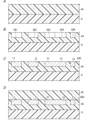
- 2A to 2D are cross-sectional views illustrating steps in a manufacturing method for the interposer.
- 3A to 3C are cross-sectional views illustrating steps in a manufacturing method for the interposer.
- FIG. 4 is a cross-sectional view of an interposer according to the second embodiment.
- 5A to 5D are cross-sectional views illustrating steps in a manufacturing method for the interposer.
- 6A to 6C are cross-sectional views illustrating steps in a manufacturing method for the interposer.
- 7A and 7B are cross-sectional views illustrating steps in a manufacturing method for the interposer.
- FIG. 8A is a plan view of a main part for explaining a manufacturing method of an interposer according to a modified example of embodiment 2.
- Fig. 8B is a cross-sectional view taken along line X1-X1 of Fig. 8A.
- FIG. 9 is a cross-sectional view of a main part for explaining a comparative example of the manufacturing method of the interposer.
- the interposer 100 is disposed between, for example, a plurality of semiconductor chips and a package substrate of a SiP (System in Package).
- the plurality of semiconductor chips include, for example, a processor, a logic IC (Integrated Circuit), a memory (for example, a High Bandwidth Memory (HBM)), etc.
- HBM High Bandwidth Memory
- the interposer 100 includes a dielectric substrate 4, a plurality of wiring portions 5, a first capacitor 1, a second capacitor 2, and a third capacitor 3.
- the plurality of wiring portions 5 penetrate the dielectric substrate 4. Note that, in FIG. 1, two of the plurality of wiring portions 5 are visible.
- the first capacitor 1, the second capacitor 2, and the third capacitor 3 are built into the dielectric substrate 4.
- the first capacitor 1, the second capacitor 2, and the third capacitor 3 have different capacitances.
- the dielectric substrate 4 has a first main surface 401 and a second main surface 402 opposite to the first main surface 401.
- the outer edge shape of the dielectric substrate 4 is rectangular, but is not limited to this.
- the dielectric substrate 4 has a first dielectric layer 41 and a second dielectric layer 42.
- the second dielectric layer 42 is laminated on the first dielectric layer 41.
- the first main surface 401 of the dielectric substrate 4 is composed of a main surface 411 of the first dielectric layer 41 opposite the second dielectric layer 42 side.
- the second main surface 402 of the dielectric substrate 4 is composed of a main surface 421 of the second dielectric layer 42 opposite the first dielectric layer 41 side.
- the material of the first dielectric layer 41 includes an organic material (e.g., polyimide resin, bismaleimide resin, or fluorine-based resin).
- organic material e.g., polyimide resin, bismaleimide resin, or fluorine-based resin.
- the material of the second dielectric layer 42 includes an organic material (e.g., polyimide resin, bismaleimide resin, or fluororesin).
- the material of the second dielectric layer 42 is the same as the material of the first dielectric layer 41, but may be different.
- the first capacitor 1 has a first electrode 11, a second electrode 12, and a first dielectric portion 13.
- the first electrode 11 and the second electrode 12 face each other in the thickness direction D1 of the dielectric substrate 4.
- the first dielectric portion 13 is interposed between the first electrode 11 and the second electrode 12.
- the outer edge shape of each of the first electrode 11 and the second electrode 12 is rectangular, but is not limited to this.
- the first electrode 11 is embedded in the first dielectric layer 41.
- the first electrode 11 is exposed from the first main surface 401 of the dielectric substrate 4.
- the first electrode 11 penetrates the first dielectric layer 41.
- the thickness of the first electrode 11 is approximately the same as the thickness of the first dielectric layer 41, and the lower surface of the first electrode 11 and the first main surface 401 of the dielectric substrate 4 are approximately flush with each other.
- the second electrode 12 is embedded in the second dielectric layer 42.
- the second electrode 12 is exposed from the second main surface 402 of the dielectric substrate 4.
- the second electrode 12 does not penetrate the second dielectric layer 42.
- the second electrode 12 is thinner than the thickness of the second dielectric layer 42 and is exposed from the second main surface 402 of the dielectric substrate 4.
- the thickness of the second electrode 12 is thinner than the thickness of the second dielectric layer 42, and the top surface of the second electrode 12 and the second main surface 402 of the dielectric substrate 4 are approximately flush with each other.
- the material of the first electrode 11 and the second electrode 12 includes, for example, copper.
- the material of the first electrode 11 and the second electrode 12 is not limited to copper, and may be, for example, a copper alloy, aluminum, or titanium.
- the material of the second electrode 12 is the same as the material of the first electrode 11, but may be different.
- the material of the first dielectric portion 13 is the same as the material of the second dielectric layer 42, and contains an organic material.
- the thickness T1 of the first dielectric portion 13 is thinner than the thickness of the second dielectric layer 42.
- the first dielectric portion 13 overlaps the second dielectric layer 42 in a direction perpendicular to the thickness direction D1 of the dielectric substrate 4.
- the first dielectric portion 13 is formed integrally with the second dielectric layer 42.
- the second capacitor 2 has a third electrode 21, a fourth electrode 22, and a second dielectric portion 23.
- the third electrode 21 and the fourth electrode 22 face each other in the thickness direction D1 of the dielectric substrate 4.
- the second dielectric portion 23 is interposed between the third electrode 21 and the fourth electrode 22.
- the outer edge shape of each of the third electrode 21 and the fourth electrode 22 is rectangular, but is not limited to this.
- the third electrode 21 is embedded in the first dielectric layer 41.
- the third electrode 21 is exposed from the first main surface 401 of the dielectric substrate 4.
- the third electrode 21 penetrates the first dielectric layer 41.
- the thickness of the third electrode 21 is approximately the same as the thickness of the first dielectric layer 41, and the lower surface of the third electrode 21 and the first main surface 401 of the dielectric substrate 4 are approximately flush with each other.
- the fourth electrode 22 is embedded in the second dielectric layer 42.
- the fourth electrode 22 is exposed from the second main surface 402 of the dielectric substrate 4.
- the fourth electrode 22 does not penetrate the second dielectric layer 42.
- the fourth electrode 22 is thinner than the thickness of the second dielectric layer 42 and is exposed from the second main surface 402 of the dielectric substrate 4.
- the thickness of the fourth electrode 22 is thinner than the thickness of the second dielectric layer 42, and the upper surface of the fourth electrode 22 and the second main surface 402 of the dielectric substrate 4 are approximately flush with each other.
- the material of the third electrode 21 and the fourth electrode 22 includes, for example, copper.
- the material of the third electrode 21 and the fourth electrode 22 is not limited to copper, and may be, for example, a copper alloy, aluminum, or titanium.
- the material of the fourth electrode 22 is the same as the material of the third electrode 21, but may be different.
- the material of the third electrode 21 is the same as the material of the first electrode 11.
- the material of the fourth electrode 22 is the same as the material of the second electrode 12.
- the material of the second dielectric portion 23 is the same as the material of the second dielectric layer 42, and contains an organic material.
- the thickness T2 of the second dielectric portion 23 is thinner than the thickness of the second dielectric layer 42.
- the second dielectric portion 23 overlaps the second dielectric layer 42 in a direction perpendicular to the thickness direction D1 of the dielectric substrate 4.
- the second dielectric portion 23 is formed integrally with the second dielectric layer 42.
- the third capacitor 3 has a fifth electrode 31, a sixth electrode 32, and a third dielectric portion 33.
- the fifth electrode 31 and the sixth electrode 32 face each other in the thickness direction D1 of the dielectric substrate 4.
- the third dielectric portion 33 is interposed between the fifth electrode 31 and the sixth electrode 32.
- the outer edge shape of each of the fifth electrode 31 and the sixth electrode 32 is rectangular, but is not limited to this.
- the fifth electrode 31 is embedded in the first dielectric layer 41.
- the fifth electrode 31 is exposed from the first main surface 401 of the dielectric substrate 4.
- the fifth electrode 31 penetrates the first dielectric layer 41.
- the thickness of the fifth electrode 31 is approximately the same as the thickness of the first dielectric layer 41, and the lower surface of the fifth electrode 31 is approximately flush with the first main surface 401 of the dielectric substrate 4.
- the sixth electrode 32 is embedded in the second dielectric layer 42.
- the sixth electrode 32 is exposed from the second main surface 402 of the dielectric substrate 4.
- the sixth electrode 32 does not penetrate the second dielectric layer 42.
- the sixth electrode 32 is thinner than the thickness of the second dielectric layer 42 and is exposed from the second main surface 402 of the dielectric substrate 4.
- the thickness of the sixth electrode 32 is thinner than the thickness of the second dielectric layer 42, and the upper surface of the sixth electrode 32 and the second main surface 402 of the dielectric substrate 4 are approximately flush with each other.
- the material of the fifth electrode 31 and the sixth electrode 32 includes, for example, copper.
- the material of the fifth electrode 31 and the sixth electrode 32 is not limited to copper, and may be, for example, a copper alloy, aluminum, or titanium.
- the material of the sixth electrode 32 is the same as the material of the fifth electrode 31, but may be different.
- the material of the fifth electrode 31 is the same as the material of the first electrode 11.
- the material of the sixth electrode 32 is the same as the material of the second electrode 12.
- the material of the third dielectric portion 33 is the same as the material of the second dielectric layer 42, and contains an organic material.
- the thickness T3 of the third dielectric portion 33 is thinner than the thickness of the second dielectric layer 42.
- the third dielectric portion 33 overlaps the second dielectric layer 42 in a direction perpendicular to the thickness direction D1 of the dielectric substrate 4.
- the third dielectric portion 33 is formed integrally with the second dielectric layer 42.
- Each of the multiple wiring parts 5 includes a first conductor part 51, a second conductor part 52, and a via conductor part 53.
- Each first conductor part 51 is embedded in the first dielectric layer 41.
- Each first conductor part 51 penetrates the first dielectric layer 41.
- the thickness of each first conductor part 51 is approximately the same as the thickness of the first dielectric layer 41, and the lower surface of each first conductor part 51 and the first main surface 401 of the dielectric substrate 4 are approximately flush with each other.
- the second conductor part 52 is embedded in the second dielectric layer 42.
- the second conductor part 52 is thinner than the thickness of the second dielectric layer 42 and is exposed from the second main surface 402 of the dielectric substrate 4.
- each second conductor part 52 is thinner than the thickness of the second dielectric layer 42, and the upper surface of each second conductor part 52 and the second main surface 402 of the dielectric substrate 4 are approximately flush with each other.
- the via conductor portion 53 is embedded in the second dielectric layer 42 and connects the first conductor portion 51 and the second conductor portion 52.
- the via conductor portion 53 is smaller than the first conductor portion 51 and smaller than the second conductor portion 52.
- the outer edge shape of the via conductor portion 53 is circular, but is not limited to this.
- the via conductor portion 53 is formed integrally with the second conductor portion 52. In other words, in each of the multiple wiring portions 5, the via conductor portion 53 is seamlessly connected to the second conductor portion 52.
- the first conductor portion 51 of one of the two wiring portions 5 in FIG. 1 is connected to the fifth electrode 31 of the third capacitor 3.
- the interposer 100 may further include a wiring portion connected to the first capacitor 1.
- the interposer 100 may further include a wiring portion connected to the second capacitor 2.
- the thickness T2 of the second dielectric portion 23 is thinner than the thickness T1 of the first dielectric portion 13, and the capacitance of the second capacitor 2 is greater than the capacitance of the first capacitor 1.
- the capacitance of the second capacitor 2 is C2
- the dielectric constant of the second dielectric portion 23 is ⁇ 2
- the opposing area between the third electrode 21 and the fourth electrode 22 is S2
- the capacitance of the third capacitor 3 is C3
- the dielectric constant of the third dielectric portion 33 is ⁇ 3
- the opposing area between the fifth electrode 31 and the sixth electrode 32 is S3
- the area of the first capacitor 1 (same value as the above-mentioned facing area S1), the area of the second capacitor 2 (same value as the above-mentioned facing area S2), and the area of the third capacitor 3 (same value as the above-mentioned facing area S3) are the same as one another in a plan view from the thickness direction D1 of the dielectric substrate 4, but may be different.
- the area of the first capacitor 1 in a plan view from the thickness direction D1 of the dielectric substrate 4 is determined by the area of the portion of the second electrode 12 that overlaps with the first electrode 11 in a plan view from the thickness direction D1 of the dielectric substrate 4.
- the area of the second capacitor 2 in a plan view from the thickness direction D1 of the dielectric substrate 4 is determined by the area of the portion of the fourth electrode 22 that overlaps with the third electrode 21 in a plan view from the thickness direction D1 of the dielectric substrate 4.
- the area of the third capacitor 3 in a plan view from the thickness direction D1 of the dielectric substrate 4 is determined by the area of the portion of the sixth electrode 32 that overlaps with the fifth electrode 31 in a plan view from the thickness direction D1 of the dielectric substrate 4.
- the support substrate 9 is, for example, an organic film, a silicon substrate, a glass substrate, or a metal substrate.
- an LCP (Liquid Crystal Polymer) film, a PET (Polyethylene terephthalate) film, a PTFE (Polytetrafluoroethylene) film, etc. can be used.
- a first resin layer 44 that is the basis of the first dielectric layer 41 is formed on the support substrate 9.
- the material of the first resin layer 44 contains the organic material (resin material) of the first dielectric layer 41.
- the thickness of the first resin layer 44 is greater than the thickness of the first dielectric layer 41.
- a solution containing the organic material of the first resin layer 44 is applied onto the support substrate 9 by a coater (e.g., a spin coater) or a dispenser, and the solution is pre-baked to form the first resin layer 44.
- the first resin layer 44 may be formed on the support substrate 9 by laminating a resin film that is to become the first resin layer 44 on the support substrate 9.
- a first recess 441, a second recess 442, a third recess 443, and a plurality of fourth recesses 444 are formed in the first resin layer 44, which define the regions in which the first electrode 11, the third electrode 21, the fifth electrode 31, and the plurality of first conductors 51 are to be formed.
- the first recess 441, the second recess 442, the third recess 443, and the plurality of fourth recesses 444 are formed in the first resin layer 44 by an imprinting method (e.g., a thermal imprinting method).
- a first mold (first metal mold) is prepared in which a first uneven pattern is formed, the first uneven pattern being patterned according to the shapes of the first electrode 11, the third electrode 21, the fifth electrode 31, and the plurality of first conductors 51.
- the first mold is pressed against the first resin layer 44 to deform and harden the first resin layer 44 (for example, by thermal hardening), thereby forming a first recess 441, a second recess 442, a third recess 443, and a plurality of fourth recesses 444 in the regions where the first electrode 11, the third electrode 21, the fifth electrode 31, and the plurality of first conductors 51 are to be formed, respectively, and the first mold is separated from the first resin layer 44.
- the opening shape of the first recess 441 corresponds to the outer edge shape of the first electrode 11 in a planar view, and the depth of the first recess 441 corresponds to the thickness of the first electrode 11.
- the opening shape of the second recess 442 corresponds to the outer edge shape of the third electrode 21 in a planar view, and the depth of the second recess 442 corresponds to the thickness of the third electrode 21.
- the opening shape of the third recess 443 corresponds to the outer edge shape of the fifth electrode 31 in a planar view, and the depth of the third recess 443 corresponds to the thickness of the fifth electrode 31.
- each of the multiple fourth recesses 444 corresponds to the outer edge shape of the first conductor 51 in a plan view, and the depth of the fourth recess 444 corresponds to the thickness of the first conductor 51.
- the first recess 441, the second recess 442, the third recess 443, and the multiple fourth recesses 444 have the same depth.
- the imprinting method is not limited to the thermal imprinting method, and may be, for example, an optical imprinting method.
- the third step includes, for example, a first step, a second step, and a third step.
- a seed layer covering the surface of the first resin layer 44 is formed, for example, by a sputtering method.
- the material of the seed layer is the same as the material of the first electrode 11, the third electrode 21, the fifth electrode 31, and the multiple first conductor parts 51, and is, for example, copper, but is not limited thereto, and may be, for example, a copper alloy, aluminum, or titanium.
- a first metal part that is the basis of the first electrode 11, the third electrode 21, the fifth electrode 31, and the multiple first conductor parts 51 is formed, for example, by electrolytic plating.
- the material of the first metal part is, for example, copper, but is not limited thereto, and may be, for example, a copper alloy, aluminum, or titanium.
- the first metal portion is subjected to CMP (Chemical Mechanical Polishing) until the first metal portion has a thickness equal to that of the first electrode 11, the third electrode 21, the fifth electrode 31, and the first conductor portions 51, thereby forming the first electrode 11, the third electrode 21, the fifth electrode 31, and the first conductor portions 51.
- the seed layer is formed by a sputtering method, but the method is not limited thereto, and the seed layer may be formed by, for example, electroless plating or chemical vapor deposition (CVD).
- the first resin layer 44 is also subjected to CMP so that the upper surfaces of the first electrode 11, the third electrode 21, the fifth electrode 31, and the first conductor portions 51 are exposed, and the main surface 440 of the first resin layer 44 is approximately flush with the upper surfaces of the first electrode 11, the third electrode 21, the fifth electrode 31, and the first conductor portions 51.
- a second resin layer 45 that is the basis of the second dielectric layer 42 is formed so as to cover the upper surfaces of the first electrode 11, the third electrode 21, the fifth electrode 31, and the multiple first conductor parts 51, and the main surface 440 of the first resin layer 44.
- the material of the second resin layer 45 contains the organic material (resin material) of the second dielectric layer 42.
- a solution containing the organic material of the second resin layer 45 is applied by a coater (e.g., a spin coater) or a dispenser so as to cover the upper surfaces of the first electrode 11, the third electrode 21, the fifth electrode 31, and the multiple first conductor parts 51, and the main surface 440 of the first resin layer 44, and the second resin layer 45 is formed by performing pre-baking.
- a coater e.g., a spin coater
- a dispenser e.g., a dispenser
- a first recess 451, a second recess 452, a third recess 453, and a plurality of fourth recesses 454 are formed in the second resin layer 45, which define the regions in which the second electrode 12, the fourth electrode 22, the sixth electrode 32, and the plurality of conductors (including the second conductor 52 and the via conductor 53) are to be formed.
- the first recess 451, the second recess 452, the third recess 453, and the plurality of fourth recesses 454 are formed in the second resin layer 45 by an imprinting method (e.g., a thermal imprinting method).
- a second mold (second metal mold) is prepared in which a second uneven pattern is formed, the second recess 451 being patterned according to the shapes of the second electrode 12, the fourth electrode 22, the sixth electrode 32, and the plurality of second conductors 52.
- the second mold is pressed against the second resin layer 45 to deform and harden the second resin layer 45 (for example, by thermal hardening), thereby forming a first recess 451, a second recess 452, a third recess 453, and a plurality of fourth recesses 454 in the regions where the second electrode 12, the fourth electrode 22, the sixth electrode 32, and the plurality of conductor portions are to be formed, and the second mold is separated from the second resin layer 45.
- the opening shape of the first recess 451 corresponds to the outer edge shape of the second electrode 12 in a plan view, and the depth of the first recess 451 corresponds to the thickness of the second electrode 12.
- the opening shape of the second recess 452 corresponds to the outer edge shape of the fourth electrode 22 in a plan view, and the depth of the second recess 452 corresponds to the thickness of the fourth electrode 22.
- the opening shape of the third recess 453 corresponds to the outer edge shape of the sixth electrode 32 in a plan view, and the depth of the third recess 453 corresponds to the thickness of the sixth electrode 32.
- the depth of the second recess 452 is deeper than the depth of the first recess 451.
- the depth of the third recess 453 is deeper than the depth of the second recess 452.
- the imprinting method is not limited to thermal imprinting, and may be, for example, optical imprinting.
- the second electrode 12, the fourth electrode 22, the sixth electrode 32, the multiple via conductors 53, and the multiple second conductors 52 are formed. More specifically, the sixth step includes, for example, a first step, a second step, and a third step.
- a seed layer covering the surface of the second resin layer 45 is formed, for example, by a sputtering method.
- the material of the seed layer is the same as the material of the second electrode 12, the fourth electrode 22, the sixth electrode 32, the multiple via conductors 53, and the multiple second conductors 52, and is, for example, copper, but is not limited thereto, and may be, for example, a copper alloy, aluminum, or titanium.
- a second metal part that is the basis of the second electrode 12, the fourth electrode 22, the sixth electrode 32, the multiple via conductors 53, and the multiple second conductors 52 is formed, for example, by electrolytic plating.
- the material of the second metal part is, for example, copper, but is not limited thereto, and may be, for example, a copper alloy, aluminum, or titanium.
- the second metal portion is CMPed until it has a thickness equal to that of the second electrode 12, the fourth electrode 22, the sixth electrode 32, and the plurality of second conductors 52, thereby forming the second electrode 12, the fourth electrode 22, the sixth electrode 32, the plurality of via conductors 53, and the plurality of second conductors 52.
- the seed layer is formed by a sputtering method, but is not limited thereto, and may be formed by, for example, electroless plating or CVD.
- the third step the upper surfaces of the second electrode 12, the fourth electrode 22, the sixth electrode 32, and the plurality of second conductors 52 are exposed, and the second resin layer 45 is also CMPed so that the main surface 450 of the second resin layer 45 is approximately flush with the upper surfaces of the second electrode 12, the fourth electrode 22, the sixth electrode 32, and the plurality of second conductors 52.
- the second resin layer 45 after CMP constitutes the second dielectric layer 42.
- the support substrate 9 and a part of the first resin layer 44 are CMPed from the main surface 92 side opposite to the first resin layer 44 side of the support substrate 9 to form a first dielectric layer 41 consisting of the remaining part of the first resin layer 44 (see FIG. 3C).
- the lower surfaces of the first electrode 11, the third electrode 21, the fifth electrode 31, and the plurality of first conductor parts 51 are exposed, and the first resin layer 44 is also CMPed so that the lower surface of the first resin layer 44 is approximately flush with the lower surfaces of the first electrode 11, the third electrode 21, the fifth electrode 31, and the plurality of first conductor parts 51.
- the support substrate 9 may be peeled off, and then a part of the first resin layer 44 may be subjected to CMP.
- an adhesive layer made of a pressure-sensitive adhesive or adhesive such as acrylic or silicone may be formed on the support substrate 9, and then the first resin layer 44 may be formed.
- the adhesive strength or bonding strength of the adhesive layer may be reduced by heating, ultraviolet light irradiation, laser light irradiation, or the like, to peel off the support substrate 9.
- the interposer 100 is formed by carrying out the first to seventh steps.
- the manufacturing method of the interposer 100 according to the first embodiment uses an imprinting method, which eliminates the need for the photolithography and dry etching steps used in the semiconductor manufacturing process, making it possible to reduce the cost of the interposer 100.
- the interposer 100 includes a dielectric substrate 4 and a first capacitor 1, a second capacitor 2, and a third capacitor 3 built into the dielectric substrate 4.
- the first capacitor 1, the second capacitor 2, and the third capacitor 3 have different capacitances.
- the thickness T2 of the second dielectric portion 23 is thinner than the thickness T1 of the first dielectric portion 13, and the capacitance of the second capacitor 2 is greater than the capacitance of the first capacitor 1.
- the thickness T3 of the third dielectric portion 33 is thinner than the thickness T2 of the second dielectric portion 23, and the capacitance of the third capacitor 3 is greater than the capacitance of the second capacitor 2.
- the interposer 100 according to the first embodiment can be miniaturized while including a plurality of capacitors (the first capacitor 1, the second capacitor 2, and the third capacitor 3) with different capacitances. More specifically, according to the interposer 100 of the first embodiment, the unit capacitances (capacity per unit area) of the first capacitor 1, the second capacitor 2, and the third capacitor 3 are different from each other, so that it is possible to achieve miniaturization compared to a case where the capacitances are made different by changing the areas of the first capacitor 1, the second capacitor 2, and the third capacitor 3 in a plan view from the thickness direction D1 of the dielectric substrate 4.
- the thickness T2 of the second dielectric portion 23 of the second capacitor 2 is thicker than the thickness T3 of the third dielectric portion 33 of the third capacitor 3, so that it is possible to improve the reliability of the second capacitor 2 more than the reliability of the third capacitor 3.
- the thickness T2 of the second dielectric portion 23 of the second capacitor 2 is thicker than the thickness T3 of the third dielectric portion 33 of the third capacitor 3, so that it is possible to make the TDDB (Time Dependent Dielectric Breakdown) of the second capacitor 2 longer than the TDDB of the third capacitor 3.
- the thickness T1 of the first dielectric portion 13 of the first capacitor 1 is greater than the thickness T2 of the second dielectric portion 23 of the second capacitor 2, it is possible to improve the reliability of the first capacitor 1 more than the reliability of the second capacitor 2.
- the thickness T1 of the first dielectric portion 13 of the first capacitor 1 is greater than the thickness T2 of the second dielectric portion 23 of the second capacitor 2, it is possible to make the TDDB of the first capacitor 1 longer than the TDDB of the second capacitor 2.
- the interposer 101 according to the second embodiment differs from the interposer 100 according to the first embodiment in that the dielectric substrate 4 further includes a third dielectric layer 43 .
- the third dielectric layer 43 is interposed between the first dielectric layer 41 and the second dielectric layer 42 in the thickness direction D1 of the dielectric substrate 4. That is, in the interposer 101 according to the second embodiment, the second dielectric layer 42 is laminated to the first dielectric layer 41 via the third dielectric layer 43.
- the material of the first dielectric portion 13, the material of the second dielectric portion 23, and the material of the second dielectric layer 42 include an organic material.
- the material of the third dielectric layer 43 is an inorganic material.
- the inorganic material includes, for example, silicon nitride or silicon oxynitride.
- the first dielectric portion 13 includes a first portion 131 formed integrally with the third dielectric layer 43, and a second portion 132 formed integrally with the second dielectric layer 42.
- the first portion 131 and the second portion 132 overlap in the thickness direction D1 of the dielectric substrate 4.
- the dielectric constant of the first portion 131 of the first dielectric portion 13 is greater than the dielectric constant of the second portion 132.
- the second dielectric portion 23 includes a third portion 231 formed integrally with the third dielectric layer 43, and a fourth portion 232 formed integrally with the second dielectric layer 42.
- the third portion 231 and the fourth portion 232 overlap in the thickness direction D1 of the dielectric substrate 4.
- the dielectric constant of the third portion 231 of the second dielectric portion 23 is greater than the dielectric constant of the fourth portion 232.
- the third dielectric portion 33 is formed integrally with the third dielectric layer 43.
- the thickness T3 of the third dielectric portion 33 is the same as the thickness of the third dielectric layer 43.
- the dielectric constant of the third dielectric portion 33 is greater than the dielectric constant of the fourth portion 232 of the second dielectric portion 23.
- the thickness T2 of the second dielectric portion 23 is thinner than the thickness T1 of the first dielectric portion 13, and the capacitance of the second capacitor 2 is greater than the capacitance of the first capacitor 1.
- the thickness T3 of the third dielectric portion 33 is thinner than the thickness T2 of the second dielectric portion 23, and the capacitance of the third capacitor 3 is greater than the capacitance of the second capacitor 2.
- the manufacturing method for the interposer 101 according to the second embodiment is substantially the same as the manufacturing method for the interposer 100 according to the first embodiment, and differs from the manufacturing method for the interposer 100 according to the first embodiment in that the third dielectric layer 43 is formed.
- the description of the same steps as those in the manufacturing method for the interposer 100 according to the first embodiment will be omitted as appropriate.
- the support substrate 9 is, for example, an organic film, a silicon substrate, a glass substrate, or a metal substrate.
- a first recess 441, a second recess 442, a third recess 443, and a plurality of fourth recesses 444 that define the planned formation regions of the first electrode 11, the third electrode 21, the fifth electrode 31, and the plurality of first conductor portions 51 are formed in the first resin layer 44.
- the first recess 441, the second recess 442, the third recess 443, and a plurality of fourth recesses 444 are formed in the first resin layer 44 by an imprinting method (e.g., a thermal imprinting method).
- the third step includes, for example, a first step, a second step, and a third step.
- a seed layer covering the surface of the first resin layer 44 is formed, for example, by a sputtering method.
- a first metal part that is the basis of the first electrode 11, the third electrode 21, the fifth electrode 31, and the multiple first conductor parts 51 is formed, for example, by electrolytic plating.
- the first metal part is subjected to CMP until it has a thickness equal to that of the first electrode 11, the third electrode 21, the fifth electrode 31, and the multiple first conductor parts 51, thereby forming the first electrode 11, the third electrode 21, the fifth electrode 31, and the multiple first conductor parts 51.
- a third dielectric layer 43 is formed, for example by a CVD method, so as to cover the upper surfaces of the first electrode 11, the third electrode 21, the fifth electrode 31, and the multiple first conductor portions 51, as well as the main surface 440 of the first resin layer 44.
- a second resin layer 45 which is the basis of the second dielectric layer 42, is formed so as to cover the third dielectric layer 43.
- a solution containing the organic material of the second resin layer 45 is applied by a coater (e.g., a spin coater) or a dispenser so as to cover the third dielectric layer 43, and the second resin layer 45 is formed by performing pre-baking.
- a first recess 451, a second recess 452, a third recess 453, and a plurality of fifth recesses 4541 are formed in the second resin layer 45, which define the regions in which the second electrode 12, the fourth electrode 22, the sixth electrode 32, and the plurality of second conductor portions 52 are to be formed.
- the first recess 451, the second recess 452, the third recess 453, and the plurality of fifth recesses 4541 are formed in the second resin layer 45 by an imprinting method (e.g., a thermal imprinting method).
- the third dielectric layer 43 functions as a stopper that limits the depth of the third recess 453 formed by the second mold.
- via holes 4542 corresponding to each of the multiple via conductors 53 are formed in the second resin layer 45 and the third dielectric layer 43 by laser processing or the like.
- the eighth step as shown in FIG. 7A, the second electrode 12, the fourth electrode 22, the sixth electrode 32, the multiple via conductors 53, and the multiple second conductors 52 are formed. More specifically, the eighth step includes, for example, a first step, a second step, and a third step.
- a seed layer covering the surface of the second resin layer 45 is formed, for example, by a sputtering method.
- the material of the seed layer is the same as the material of the second electrode 12, the fourth electrode 22, the sixth electrode 32, the multiple via conductors 53, and the multiple second conductors 52, and is, for example, copper, but is not limited thereto, and may be, for example, a copper alloy, aluminum, or titanium.
- a second metal part that is the basis of the second electrode 12, the fourth electrode 22, the sixth electrode 32, the multiple via conductors 53, and the multiple second conductors 52 is formed, for example, by electrolytic plating.
- the material of the second metal part is, for example, copper, but is not limited thereto, and may be, for example, a copper alloy, aluminum, or titanium.
- the second metal portion is CMPed until it has a thickness equal to that of the second electrode 12, the fourth electrode 22, the sixth electrode 32, and the plurality of second conductors 52, thereby forming the second electrode 12, the fourth electrode 22, the sixth electrode 32, the plurality of via conductors 53, and the plurality of second conductors 52.
- the second resin layer 45 is also CMPed so that the upper surfaces of the second electrode 12, the fourth electrode 22, the sixth electrode 32, and the plurality of second conductors 52 are exposed, and the main surface 450 of the second resin layer 45 is approximately flush with the upper surfaces of the second electrode 12, the fourth electrode 22, the sixth electrode 32, and the plurality of second conductors 52.
- the second resin layer 45 after CMP constitutes the second dielectric layer 42.
- the support substrate 9 and a portion of the first resin layer 44 are CMPed from the main surface 92 side of the support substrate 9 opposite the first resin layer 44 side, thereby forming a first dielectric layer 41 consisting of the remaining portion of the first resin layer 44 (see FIG. 7B).
- the first resin layer 44 is also CMPed so that the lower surfaces of the first electrode 11, the third electrode 21, the fifth electrode 31, and the multiple first conductors 51 are exposed, and the lower surface of the first resin layer 44 is approximately flush with the lower surfaces of the first electrode 11, the third electrode 21, the fifth electrode 31, and the multiple first conductors 51.
- the ninth step it is essential that the lower surfaces of the first electrode 11, the third electrode 21, the fifth electrode 31, and the multiple first conductors 51 are exposed, but it is not essential that the lower surface of the first resin layer 44 is substantially flush with the lower surfaces of the first electrode 11, the third electrode 21, the fifth electrode 31, and the multiple first conductors 51.
- the interposer 101 is formed by carrying out the first to ninth steps.
- the first capacitor 1, the second capacitor 2, and the third capacitor 3 have different capacitances, similar to the interposer 100 according to the first embodiment.
- the thickness T2 of the second dielectric portion 23 is thinner than the thickness T1 of the first dielectric portion 13, and the capacitance of the second capacitor 2 is larger than the capacitance of the first capacitor 1, similar to the interposer 100 according to the first embodiment.
- the thickness T3 of the third dielectric portion 33 is thinner than the thickness T2 of the second dielectric portion 23, and the capacitance of the third capacitor 3 is larger than the capacitance of the second capacitor 2.
- the interposer 101 according to the second embodiment can be miniaturized while having a plurality of capacitors (the first capacitor 1, the second capacitor 2, and the third capacitor 3) with different capacitances, similar to the interposer 100 according to the first embodiment.
- the dielectric substrate 4 has a third dielectric layer 43 having a larger dielectric constant than the first dielectric layer 41 and the second dielectric layer 42, so that the capacitances of the first capacitor 1, the second capacitor 2, and the third capacitor 3 can be made larger than the capacitances of the first capacitor 1, the second capacitor 2, and the third capacitor 3, respectively, in the interposer 100 according to the first embodiment.
- the interposer 101 according to the second embodiment can reduce the variation in the thickness of the third dielectric portion 33, and can reduce the variation in the capacitance of the third capacitor 3.
- the material of the third dielectric layer 43 contains silicon nitride or silicon oxynitride (in other words, the third dielectric layer 43 is composed of a silicon nitride layer or a silicon oxynitride layer), so that the diffusion of copper contained in the constituent elements of the first electrode 11, the third electrode 21, and the fifth electrode 31 can be suppressed, and at least one of improving electromigration resistance and extending the TDDB time can be achieved.
- the material of the third dielectric layer 43 is not limited to silicon nitride or silicon oxynitride, so long as it is an inorganic material.
- the interposers 100 and 101 may include the third capacitor 3, but may not include the third capacitor 3.
- the interposers 100 and 101 may include a plurality of capacitors including at least the first capacitor 1 and the second capacitor 2, and may not include the third capacitor 3, or may include four or more capacitors including the first capacitor 1 and the second capacitor 2, each having a different thickness of the dielectric portion and a different capacitance.
- the plurality of capacitors may include two capacitors having the same capacitance.
- a plurality of insulating pillars 46 penetrating the first electrode 11 may be provided.
- the area of the first electrode 11 is increased, dishing may occur due to CMP in the third step, and the flatness may decrease as shown in Figure 9.
- dishing during CMP can be suppressed, and the variation in the capacitance of the first capacitor 1 can be reduced.
- FIGs 8A and 8B only the first electrode 11 is illustrated among the first electrode 11, the third electrode 21, and the fifth electrode 31, but a plurality of insulating pillars 46 may also be provided on each of the third electrode 21 and the fifth electrode 31.
- the material of the insulating pillars 46 is, for example, the same as the material of the first resin layer 44.
- the insulating pillars 46 are integrally formed with the first resin layer 44. Therefore, in the interposers 100 and 101, the material of the insulating pillars 46 is the same as the material of the first dielectric layer 41.
- the interposers 100 and 101 may also include a support substrate 9.
- the first resin layer 44 (see Figs. 3B and 7A) may form the first dielectric layer 41
- the support substrate 9 may be provided with a plurality of through-wiring parts connected one-to-one to the first capacitor 1, the second capacitor 2, the third capacitor 3, and each wiring part 5, for example.
- the material of each of the first dielectric layer 41 and the second dielectric layer 42 is not limited to an organic material, and may be, for example, an inorganic material (e.g., ceramic, etc.).
- the dielectric substrate 4 may have one or more dielectric layers in addition to the first dielectric layer 41 and the second dielectric layer 42.Furthermore, in the interposer 100, the dielectric substrate 4 may have one or more dielectric layers in addition to the first dielectric layer 41, the second dielectric layer 42, and the third dielectric layer 43.
- the dielectric substrate 4 has multiple dielectric layers, but having multiple dielectric layers is not essential.
- the material of the third dielectric layer 43 may be an organic material having a higher Young's modulus than the material of the first dielectric portion 13, the material of the second dielectric portion 23, and the material of the second dielectric layer 42.
- the interposer (100; 101) of the first aspect comprises a dielectric substrate (4), a wiring portion (5), a first capacitor (1) and a second capacitor (2).
- the dielectric substrate (4) has a first main surface (401) and a second main surface (402) opposite to the first main surface (401).
- the wiring portion (5) penetrates the dielectric substrate (4).
- the first capacitor (1) and the second capacitor (2) are built into the dielectric substrate (4).
- the first capacitor (1) and the second capacitor (2) have different capacitances.
- the first capacitor (1) has a first electrode (11), a second electrode (12), and a first dielectric portion (13).
- the first electrode (11) and the second electrode (12) face each other in the thickness direction (D1) of the dielectric substrate (4).
- the first dielectric portion (13) is interposed between the first electrode (11) and the second electrode (12).
- the second capacitor (2) has a third electrode (21), a fourth electrode (22), and a second dielectric portion (23).
- the third electrode (21) and the fourth electrode (22) face each other in the thickness direction (D1) of the dielectric substrate (4).
- the second dielectric portion (23) is interposed between the third electrode (21) and the fourth electrode (22).
- the thickness (T2) of the second dielectric portion (23) is thinner than the thickness (T1) of the first dielectric portion (13), and the capacitance of the second capacitor (2) is greater than the capacitance of the first capacitor (1).
- This aspect makes it possible to achieve miniaturization while providing multiple capacitors with different capacitances (first capacitor 1 and second capacitor 2).
- the dielectric substrate (4) has a first dielectric layer (41) and a second dielectric layer (42).
- the second dielectric layer (42) is laminated on the first dielectric layer (41).
- the first electrode (11) and the third electrode (21) are embedded in the first dielectric layer (41).
- the second electrode (12) and the fourth electrode (22) are embedded in the second dielectric layer (42).
- the first dielectric portion (13) and the second dielectric portion (23) overlap the second dielectric layer (42) in a direction perpendicular to the thickness direction (D1) of the dielectric substrate (4).
- the material of the first dielectric portion (13), the material of the second dielectric portion (23), and the material of the second dielectric layer (42) include an organic material.
- the material of the first dielectric layer (41) is the same as the material of the second dielectric layer (42).
- the dielectric substrate (4) further includes a third dielectric layer (43).
- the third dielectric layer (43) is interposed between the first dielectric layer (41) and the second dielectric layer (42).
- the material of the first dielectric portion (13), the material of the second dielectric portion (23), and the material of the second dielectric layer (42) include an organic material.
- the material of the third dielectric layer (43) is an organic material having a higher Young's modulus than the material of the first dielectric portion (13), the material of the second dielectric portion (23), and the material of the second dielectric layer (42).
- the first dielectric portion (13) includes a first portion (131) formed integrally with the third dielectric layer (43) and a second portion (132) formed integrally with the second dielectric layer (42).
- the second dielectric portion (23) includes a third portion (231) that is integrally formed with the third dielectric layer (43).
- the dielectric substrate (4) further includes a third dielectric layer (43).
- the third dielectric layer (43) is interposed between the first dielectric layer (41) and the second dielectric layer (42).
- the material of the third dielectric layer (43) is an inorganic material.
- the wiring portion (5) includes a first conductor portion (51), a second conductor portion (52), and a via conductor portion (53).
- the first conductor portion (51) penetrates the first dielectric layer (41).
- the second conductor portion (52) is embedded in the second dielectric layer (42).
- the second conductor portion (52) is thinner than the thickness of the second dielectric layer (42) and is exposed from the second main surface (402) of the dielectric substrate (4).
- the via conductor portion (53) is embedded in the second dielectric layer (42) and connects the first conductor portion (51) and the second conductor portion (52).
- the first electrode (11), the second electrode (12), the third electrode (21), the fourth electrode (22) and the wiring portion (5) contain the same metal.
- This aspect makes it possible to reduce costs.
- First capacitor 11 First electrode 12 Second electrode 13 First dielectric portion 131 First portion 132 Second portion 2 Second capacitor 21 Third electrode 22 Fourth electrode 23 Second dielectric portion 231 Third portion 232 Fourth portion 3 Third capacitor 31 Fifth electrode 32 Sixth electrode 33 Third dielectric portion 4 Dielectric substrate 41 First dielectric layer 42 Second dielectric layer 43 Third dielectric layer 401 First main surface 402 Second main surface 5 Wiring portion 51 First conductor portion 52 Second conductor portion 53 Via conductor portion 100, 101 Interposer D1 Thickness direction T1 Thickness T2 Thickness T3 Thickness
Landscapes
- Engineering & Computer Science (AREA)
- Power Engineering (AREA)
- Microelectronics & Electronic Packaging (AREA)
- Manufacturing & Machinery (AREA)
- Production Of Multi-Layered Print Wiring Board (AREA)
Priority Applications (2)
| Application Number | Priority Date | Filing Date | Title |
|---|---|---|---|
| JP2024576252A JPWO2024166733A1 (https=) | 2023-02-06 | 2024-01-29 | |
| CN202480007354.0A CN120435766A (zh) | 2023-02-06 | 2024-01-29 | 中介板 |
Applications Claiming Priority (2)
| Application Number | Priority Date | Filing Date | Title |
|---|---|---|---|
| JP2023016287 | 2023-02-06 | ||
| JP2023-016287 | 2023-02-06 |
Publications (1)
| Publication Number | Publication Date |
|---|---|
| WO2024166733A1 true WO2024166733A1 (ja) | 2024-08-15 |
Family
ID=92262441
Family Applications (1)
| Application Number | Title | Priority Date | Filing Date |
|---|---|---|---|
| PCT/JP2024/002675 Ceased WO2024166733A1 (ja) | 2023-02-06 | 2024-01-29 | インタポーザ |
Country Status (3)
| Country | Link |
|---|---|
| JP (1) | JPWO2024166733A1 (https=) |
| CN (1) | CN120435766A (https=) |
| WO (1) | WO2024166733A1 (https=) |
Citations (3)
| Publication number | Priority date | Publication date | Assignee | Title |
|---|---|---|---|---|
| JP2003051501A (ja) * | 2001-05-30 | 2003-02-21 | Mitsubishi Electric Corp | 半導体装置及びその製造方法 |
| JP2009170646A (ja) * | 2008-01-16 | 2009-07-30 | Nec Corp | キャパシタ、キャパシタ内蔵配線基板、及びその製造方法 |
| JP2020191377A (ja) * | 2019-05-22 | 2020-11-26 | 株式会社アドヴィックス | 回路基板 |
-
2024
- 2024-01-29 JP JP2024576252A patent/JPWO2024166733A1/ja active Pending
- 2024-01-29 WO PCT/JP2024/002675 patent/WO2024166733A1/ja not_active Ceased
- 2024-01-29 CN CN202480007354.0A patent/CN120435766A/zh active Pending
Patent Citations (3)
| Publication number | Priority date | Publication date | Assignee | Title |
|---|---|---|---|---|
| JP2003051501A (ja) * | 2001-05-30 | 2003-02-21 | Mitsubishi Electric Corp | 半導体装置及びその製造方法 |
| JP2009170646A (ja) * | 2008-01-16 | 2009-07-30 | Nec Corp | キャパシタ、キャパシタ内蔵配線基板、及びその製造方法 |
| JP2020191377A (ja) * | 2019-05-22 | 2020-11-26 | 株式会社アドヴィックス | 回路基板 |
Also Published As
| Publication number | Publication date |
|---|---|
| CN120435766A (zh) | 2025-08-05 |
| JPWO2024166733A1 (https=) | 2024-08-15 |
Similar Documents
| Publication | Publication Date | Title |
|---|---|---|
| JP3961537B2 (ja) | 半導体搭載用配線基板の製造方法、及び半導体パッケージの製造方法 | |
| US7977763B2 (en) | Chip package with die and substrate | |
| JP6342120B2 (ja) | 超薄埋設ダイモジュール及びその製造方法 | |
| US7786587B2 (en) | Semiconductor device and method for manufacturing thereof | |
| CN102468264B (zh) | 凸起结构、半导体封装件及其制造方法 | |
| US12557215B2 (en) | Semiconductor package using flip-chip technology | |
| TWI690045B (zh) | 構裝結構、其接合方法及用於其的線路板 | |
| JP2013243345A5 (https=) | ||
| JP2009027174A (ja) | システムインパッケージ及びその製造方法 | |
| US12051616B2 (en) | Wafer level chip scale packaging intermediate structure apparatus and method | |
| JP2007115776A (ja) | 半導体チップ及びその製造方法 | |
| JP2016004992A (ja) | パッケージ方法 | |
| CN100524717C (zh) | 芯片内埋的模块化结构 | |
| US6784519B2 (en) | Semiconductor device | |
| TWI857363B (zh) | 半導體基板結構及其製造方法 | |
| US20250029911A1 (en) | Manufacturing method of semiconductor substrate | |
| WO2024166733A1 (ja) | インタポーザ | |
| JP2009004813A (ja) | 半導体搭載用配線基板 | |
| CN118335626A (zh) | 一种嵌入式混合结构基板及其制作方法 | |
| US7244647B2 (en) | Embedded capacitor structure in circuit board and method for fabricating the same | |
| TWI918032B (zh) | 晶片封裝體及其製造方法 | |
| WO2025187364A1 (ja) | インターポーザ、構造体及び電子部品モジュール | |
| JP2007096337A (ja) | 半導体搭載用配線基板、半導体パッケージ、及びその製造方法 | |
| CN118676066B (zh) | 电子封装件及其制法 | |
| TWI879344B (zh) | 半導體結構及其製造方法 |
Legal Events
| Date | Code | Title | Description |
|---|---|---|---|
| 121 | Ep: the epo has been informed by wipo that ep was designated in this application |
Ref document number: 24753177 Country of ref document: EP Kind code of ref document: A1 |
|
| WWE | Wipo information: entry into national phase |
Ref document number: 202480007354.0 Country of ref document: CN |
|
| ENP | Entry into the national phase |
Ref document number: 2024576252 Country of ref document: JP Kind code of ref document: A |
|
| WWE | Wipo information: entry into national phase |
Ref document number: 2024576252 Country of ref document: JP |
|
| WWP | Wipo information: published in national office |
Ref document number: 202480007354.0 Country of ref document: CN |
|
| NENP | Non-entry into the national phase |
Ref country code: DE |
|
| 122 | Ep: pct application non-entry in european phase |
Ref document number: 24753177 Country of ref document: EP Kind code of ref document: A1 |