WO2024166633A1 - 駆動装置および光学機器 - Google Patents
駆動装置および光学機器 Download PDFInfo
- Publication number
- WO2024166633A1 WO2024166633A1 PCT/JP2024/001195 JP2024001195W WO2024166633A1 WO 2024166633 A1 WO2024166633 A1 WO 2024166633A1 JP 2024001195 W JP2024001195 W JP 2024001195W WO 2024166633 A1 WO2024166633 A1 WO 2024166633A1
- Authority
- WO
- WIPO (PCT)
- Prior art keywords
- power transmission
- transmission member
- lead screw
- lens frame
- drive device
- Prior art date
- Legal status (The legal status is an assumption and is not a legal conclusion. Google has not performed a legal analysis and makes no representation as to the accuracy of the status listed.)
- Ceased
Links
Images




Classifications
-
- G—PHYSICS
- G02—OPTICS
- G02B—OPTICAL ELEMENTS, SYSTEMS OR APPARATUS
- G02B7/00—Mountings, adjusting means, or light-tight connections, for optical elements
- G02B7/02—Mountings, adjusting means, or light-tight connections, for optical elements for lenses
- G02B7/04—Mountings, adjusting means, or light-tight connections, for optical elements for lenses with mechanism for focusing or varying magnification
-
- F—MECHANICAL ENGINEERING; LIGHTING; HEATING; WEAPONS; BLASTING
- F16—ENGINEERING ELEMENTS AND UNITS; GENERAL MEASURES FOR PRODUCING AND MAINTAINING EFFECTIVE FUNCTIONING OF MACHINES OR INSTALLATIONS; THERMAL INSULATION IN GENERAL
- F16H—GEARING
- F16H25/00—Gearings comprising primarily only cams, cam-followers and screw-and-nut mechanisms
- F16H25/18—Gearings comprising primarily only cams, cam-followers and screw-and-nut mechanisms for conveying or interconverting oscillating or reciprocating motions
- F16H25/20—Screw mechanisms
- F16H25/24—Elements essential to such mechanisms, e.g. screws, nuts
-
- G—PHYSICS
- G03—PHOTOGRAPHY; CINEMATOGRAPHY; ANALOGOUS TECHNIQUES USING WAVES OTHER THAN OPTICAL WAVES; ELECTROGRAPHY; HOLOGRAPHY
- G03B—APPARATUS OR ARRANGEMENTS FOR TAKING PHOTOGRAPHS OR FOR PROJECTING OR VIEWING THEM; APPARATUS OR ARRANGEMENTS EMPLOYING ANALOGOUS TECHNIQUES USING WAVES OTHER THAN OPTICAL WAVES; ACCESSORIES THEREFOR
- G03B17/00—Details of cameras or camera bodies; Accessories therefor
- G03B17/02—Bodies
- G03B17/12—Bodies with means for supporting objectives, supplementary lenses, filters, masks, or turrets
- G03B17/14—Bodies with means for supporting objectives, supplementary lenses, filters, masks, or turrets interchangeably
-
- F—MECHANICAL ENGINEERING; LIGHTING; HEATING; WEAPONS; BLASTING
- F16—ENGINEERING ELEMENTS AND UNITS; GENERAL MEASURES FOR PRODUCING AND MAINTAINING EFFECTIVE FUNCTIONING OF MACHINES OR INSTALLATIONS; THERMAL INSULATION IN GENERAL
- F16H—GEARING
- F16H25/00—Gearings comprising primarily only cams, cam-followers and screw-and-nut mechanisms
- F16H25/18—Gearings comprising primarily only cams, cam-followers and screw-and-nut mechanisms for conveying or interconverting oscillating or reciprocating motions
- F16H25/20—Screw mechanisms
-
- G—PHYSICS
- G03—PHOTOGRAPHY; CINEMATOGRAPHY; ANALOGOUS TECHNIQUES USING WAVES OTHER THAN OPTICAL WAVES; ELECTROGRAPHY; HOLOGRAPHY
- G03B—APPARATUS OR ARRANGEMENTS FOR TAKING PHOTOGRAPHS OR FOR PROJECTING OR VIEWING THEM; APPARATUS OR ARRANGEMENTS EMPLOYING ANALOGOUS TECHNIQUES USING WAVES OTHER THAN OPTICAL WAVES; ACCESSORIES THEREFOR
- G03B2217/00—Details of cameras or camera bodies; Accessories therefor
- G03B2217/002—Details of arrangement of components in or on camera body
Definitions
- the present invention relates to a drive device that drives a driven member.
- Patent Document 1 discloses a configuration in which a steel ball is meshed with the lead screw, and a sliding member that holds the steel ball in a recess is connected to the driven member via a leaf spring.
- Patent Document 2 discloses a configuration in which a rack is meshed with the lead screw, and the rack is connected to the driven member.
- the present invention provides a drive device that can reduce losses when driving a driven member via a power transmission member that meshes with the lead screw.
- a driving device as one aspect of the present invention has a driven member that can move in a linear direction, a lead screw that is rotationally driven by an actuator, and a power transmission member that is supported by the driven member on the inner diameter side and engages with the lead screw on the outer diameter side, transmitting a linear driving force generated by rotation of the lead screw to the driven member.
- the power transmission member is characterized in that it is supported so that it can rotate together with the rotation of the lead screw.
- the present invention makes it possible to reduce losses when driving a driven member via a power transmission member that meshes with the lead screw.
- FIG. 1A and 1B are a perspective view and a cross-sectional view illustrating a configuration of a lens driving device according to a first embodiment.
- FIG. 2 is a diagram showing details of the lens driving device according to the first embodiment.
- FIG. 2 is a diagram showing a power transmission member according to the first embodiment.
- 5A to 5C are diagrams illustrating a backlash and a contact state of the power transmission member during driving in the first embodiment.
- 6 is another diagram illustrating the backlash and contact state of the power transmission member during driving in the first embodiment.
- FIG. 5A to 5C are diagrams for explaining the principle of loss reduction in the first embodiment.
- 11A and 11B are a perspective view and a cross-sectional view showing a configuration of a lens driving device according to a second embodiment.
- FIG. 11 is a partial cross-sectional view of the lens driving device according to the second embodiment.
- FIG. 1(b) shows a lens driving device 100 according to the first embodiment.
- the lens driving device 100 is mounted on an optical device such as an interchangeable lens that can be attached to an imaging device or an imaging device with a lens barrel.
- FIG. 1(a) shows a part of the lens driving device 100.
- the lens driving device 100 has a fixed member 101 having a hollow cylindrical shape, a lens frame 102 as a driven member disposed within the fixed member 101, and a main guide bar 103 and a sub guide bar 104 as guide means.
- the lens driving device 100 further has an actuator 105, a power transmission member 107, and an abutment member 108.
- the fixed member 101 is a part of the optical device.
- the lens frame 102 which serves as an optical element holding member, holds a lens (not shown) as an optical element.
- an optical element holding member that holds an optical element other than a lens such as an aperture
- the main guide bar 103 and the sub guide bar 104 are fixed in the fixed member 101 by having both ends held by bar fixing parts 101a and 101b provided on the inner surface of the fixed member 101.
- the sleeve part 102a of the lens frame 102 is engaged with the main guide bar 103 so as to be movable in the axial direction
- the rotation stop part 102b of the lens frame 102 is engaged with the sub guide bar 104 so as to be movable in the axial direction.
- the lens frame 102 is guided in the axial direction by the main guide bar 103 at the sleeve part 102a. Furthermore, the rotation stop part 102b is engaged with the sub guide bar 104, thereby preventing the lens frame 102 from rotating around the main guide bar 103.
- the actuator 105 is a rotary drive source such as a stepping motor, and is fixed to the fixed member 101.
- a lead screw 106 is provided on the output shaft of the actuator 105.
- the axial direction of the lead screw 106 is parallel to the axial directions of the main guide bar 103 and the sub guide bar 104, and in the following description, these axial directions are referred to as the optical axis direction.
- the side on which the actuator 105 is provided is referred to as the rear side
- the side from which the lead screw 106 extends from the actuator 105 is referred to as the front side.
- the front end of the lead screw 106 is rotatably held by a holding plate 109 fixed to the actuator 105.
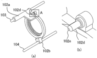
- FIG. 2(a) shows the details of the shape of the lens frame 102.
- FIG. 2(b) shows an enlarged view of part A in FIG. 2(a).
- the lens frame 102 is provided with a support shaft portion 102d that extends from the rear side to the front side.
- the support shaft portion 102d rotatably supports the power transmission member 107 shown in FIGS. 1(a) and (b) on its inner diameter side.
- the member corresponding to the support shaft portion 102d may be manufactured as a separate member from the lens frame 102 and fixed to the lens frame 102 by adhesive or other methods. In this case, another member may be interposed between the lens frame 102 and the member corresponding to the support shaft portion 102d. In such a case, the power transmission member 107 can be considered to be supported by the lens frame 102.
- Figures 3(a) to (c) show the details of the shape of the power transmission member 107.
- Figure 3(a) shows the state in which multiple teeth of the power transmission member 107, which will be described later, are engaged with the lead screw 106
- Figures 3(b) and 3(c) show the power transmission member 107 as viewed from the diagonal rear and diagonal front, respectively.
- the power transmission member 107 has a cylindrical base shape, and has multiple teeth 107a, 107b, 107c, and 107d formed on its outer periphery (outer diameter side) at predetermined intervals in the optical axis direction. These teeth 107a to 107d extend around the entire circumference of the power transmission member 107 in the rotational direction, and always engage with the threads of the lead screw 106 regardless of the rotation of the power transmission member 107.
- the power transmission member 107 is formed with a connecting portion 107e that is a cylindrical recess that is open at the rear.
- the support shaft portion 102d of the lens frame 102 is inserted into this connecting portion 107e (see FIG. 4(a)), so that the power transmission member 107 is supported so as to be rotatable around the support shaft portion 102d.
- the front end surface 102e of the support shaft portion 102d shown in FIG. 2(b) is a surface that can abut against the front end surface inside the connecting portion 107e of the power transmission member 107.
- the forward movement of the power transmission member 107 relative to the lens frame 102 is prevented by the front end abutment portion 107f of the power transmission member 107 abutting against the abutment member 108 fixed to the lens frame 102 as shown in Figures 1(a) and (b) as shown in Figures 3(c).
- the abutment member 108 is manufactured as a separate member from the lens frame 102 and fixed to the lens frame 102, but even in this case, it can be considered that the power transmission member 107 abuts against the lens frame 102.
- a part equivalent to the abutment member 108 may be provided integrally with the lens frame 102.
- the actuator 105 when the actuator 105 is driven to rotate the lead screw 106, the rotation of the lead screw 106 is converted into a driving force in the optical axis direction (linear direction) by the meshing of the lead screw 106 with the power transmission member 107.
- the power transmission member 107 transmits the driving force to the lens frame 102.
- the lens frame 102 is guided in the optical axis direction by the main guide bar 103 (and sub guide bar 104) and driven linearly in the same direction.
- the power transmission member 107 rotates relative to the lens frame 102 (support shaft portion 102d) while moving in the optical axis direction in mesh with the rotating lead screw 106.
- the rotational resistance (torque) generated by the coupling portion 107e of the power transmission member 107 sliding in the rotational direction relative to the support shaft portion 102d is defined as T1.
- the rotational resistance generated by the power transmission member 107 when the first to fourth tooth portions 107a to 107d of the power transmission member 107 slip against the threads of the lead screw 106 is defined as T2.
- the "slip” referred to here does not include minute (microscopic) slippage that cannot be seen with the naked eye. In other words, "slip” means slippage of a specific amount (e.g., 3%) or more that can be clearly confirmed with the naked eye.
- the present embodiment satisfies the condition of the following formula (1).
- Rotational resistance T1 Rotational resistance T2 (1)
- the power transmission member 107 can rotate relative to the lens frame 102 while meshing with the lead screw 106 without slipping on the threads of the lead screw 106.
- FIG. 4(a) shows the state in which the play between the above-mentioned parts is eliminated when the lens frame 102 is driven in the direction G1.
- FIG. 4(b) shows an enlarged view of part B in FIG. 4(a).
- the thread appears to move in the direction G1.
- the play between the thread of the lead screw 106 and the teeth of the power transmission member 107 is eliminated on the G1 side. In other words, the thread of the lead screw 106 abuts against the teeth of the power transmission member 107 from the direction G1.
- the power transmission member 107 abuts against the lens frame 102 (the front end surface 102e of the support shaft portion 102d), and thus the play between them is also eliminated. After the play is eliminated in this way, the lens frame 102 is driven in the direction G1.
- FIG. 5(a) shows the state where the play between the above-mentioned parts is eliminated when the lens frame 102 is driven in the direction G2.
- FIG. 5(b) shows an enlarged view of part C in FIG. 5(a).
- the thread appears to move in the direction G2.
- the play between the thread of the lead screw 106 and the teeth of the power transmission member 107 is eliminated on the G2 side.
- the thread of the lead screw 106 abuts against the teeth of the power transmission member 107 from the direction G2.
- the power transmission member 107 front end abutment portion 107f abuts against the abutment member 108, so that the play between them is also eliminated.
- the lens frame 102 is driven in the direction G2.
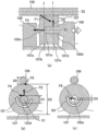
- FIG. 6(a) shows the forces F1, F2, and F3 that the power transmission member 107 receives primarily when the lens frame 102 is driven in the direction G1.
- FIG. 6(b) shows a cross section taken along the cutting line I in FIG. 6(a). This figure shows the resistance force F4 against the rotation of the power transmission member 107 that occurs when the power transmission member 107 rotates in the direction G3 while receiving the force F2, and the tangential force F5 that occurs when the lead screw 106 rotates the power transmission member 107.
- FIG. 6(c) shows a cross section taken along the cutting line J in FIG. 6(a).
- the diameter (inner diameter) of the connecting portion 107e of the power transmission member 107 is D1.
- the diameter (outer diameter) of the support shaft portion 102d of the lens frame 102 is set slightly smaller than the diameter D1 of the power transmission member 107 so that the power transmission member 107 is allowed to rotate around the support shaft portion 102d.
- each tooth portion of the power transmission member 107 that meshes with the lead screw 106 is D2
- the diameter of the front end surface 102e of the support shaft portion 102d of the lens frame 102 is D3
- the diameter (effective diameter of the thread) of the lead screw 106 is D0.
- Force F1 is the force that the lead screw 106, to which torque from the energized actuator 105 is input, exerts on the power transmission member 107, and is generated in a direction perpendicular to the teeth (107a to 107d) of the power transmission member 107 with which the threads of the lead screw 106 abut. Force F1 increases when driving a lens frame 102 with a larger mass or when driving the lens frame 102 with a larger acceleration. Note that F1 is the resultant force of the forces that the first to fourth teeth 107a to 107d of the power transmission member 107 receive from the lead screw 106.
- Force F2 is a force that the power transmission member 107 receives from the support shaft portion 102d of the lens frame 102 in a direction perpendicular to direction G1.
- Force F3 is a force that the power transmission member 107 receives from the front end face 102e of the support shaft portion 102d of the lens frame 102 in the direction opposite to direction G1.
- T6 F6 ⁇ (D3/2) (7)
- the diameter D3 becomes almost zero, and the rotational resistance T6 also becomes almost zero. becomes a very small value.
- the resistance force F4 due to the force F2 generated at the diameter D1 is reduced in accordance with (D2/D1) at the position of the diameter D2.
- the resistance force F6 at the diameter D3 generated between the power transmission member 107 and the lens frame 102 becomes smaller in accordance with (D2/D3) at the position of the diameter D2 of the teeth of the power transmission member 107.
- the rotational resistance T6 has almost no effect on the tangential force F5 applied by the lead screw 106 to rotate the power transmission member 107, and can be ignored.
- the front end abutment portion 107f of the power transmission member 107 that abuts against the abutment member 108 also have a curved shape such as a spherical surface.
- the lead screw 106 and the power transmission member 107 rotate relative to each other with almost no slippage, so that no resistance force such as friction due to the force F1 occurs, and a resistance force F4 such as friction due to the force F2 occurs.
- the tangential force F5 of the lead screw 106 required to rotate the power transmission member 107 is reduced by reducing the resistance forces F4 and F6 according to (F1/F2) and (D2/D1). Therefore, in a configuration using the power transmission member 107 as in this embodiment, the load on the lead screw 106 (that is, the actuator 105) can be reduced according to (F1/F2) and (D2/D1).
- the loss when transmitting the driving force from the lead screw 106 to the power transmission member 107 can be reduced. Therefore, the driving force applied to the lens frame 102 can be increased relative to the torque input transmitted from the actuator 105 to the lead screw 106, and a lens driving device 100 with high driving efficiency can be realized.
- the lead screw diameter is 1.6 mm
- the angle between the teeth of the power transmission member (rack, etc.) and the thread of the lead screw is 60°
- the coefficient of sliding friction between the teeth and the thread is 0.1
- the force corresponding to F1 is 1 N.
- the load torque of the lead screw is 0.08 mmN.
- D2 is 6 mm
- D1 is 1 mm
- the lead screw diameter is 1.6 mm
- the angle between each tooth of the power transmission member 107 and the thread of the lead screw 106 is 60°
- the sliding friction coefficient between the support shaft portion 102d and the connecting portion 107e is 0.1
- F1 is 1 N.
- the load torque of the lead screw 106 is 0.007 mmN.
- the load torque of the lead screw 106 can be significantly reduced compared to the conventional configuration.
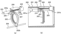
- FIG. 7(b) shows a lens driving device 200 according to the second embodiment.
- FIG. 7(a) shows a part of the lens driving device 200.
- components that are common to or similar to those of the first embodiment are given the same names as those used in the first embodiment.
- the lens driving device 200 has a fixed member 201 having a hollow cylindrical shape, a lens frame 202 as a driven member disposed within the fixed member 201, and a main guide bar 203 and a sub guide bar 204 as guide means.
- the lens driving device 200 further has an actuator 205, a power transmission member 207, and an abutment member 208.
- the lens frame 202 holds a lens (not shown).
- the main guide bar 203 and the sub guide bar 204 are fixed within the fixed member 201 by having both ends held by fixing portions 201a and 201b provided on the inner surface of the fixed member 201.
- the sleeve portion 202a of the lens frame 202 engages with the main guide bar 203 so as to be movable in the optical axis direction
- the anti-rotation portion 202b of the lens frame 202 engages with the sub-guide bar 204 so as to be movable in the optical axis direction.
- the lens frame 202 is guided in the optical axis direction by the main guide bar 203 at the sleeve portion 202a.
- the anti-rotation portion 202b engages with the sub-guide bar 204, thereby preventing the lens frame 202 from rotating around the main guide bar 203.
- the actuator 205 is a rotary drive source such as a stepping motor, and is fixed to the fixed member 201.
- a lead screw 206 is provided on the output shaft of the actuator 205.
- the axial directions of the lead screw 206, main guide bar 203, and sub guide bar 204 are parallel to the optical axis direction.
- the front end of the lead screw 206 is rotatably held by a holding plate 209 fixed to the actuator 205.
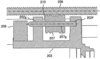
- FIG. 8 shows the structure for holding the power transmission member 207 in the lens frame 202.
- the power transmission member 207 has first to fourth teeth, similar to the power transmission member 107 in Example 1.
- the diameter of each tooth is D2, the same as in Example 1.
- a through hole 207g extending in the optical axis direction is formed in the center of the power transmission member 207, and a connecting shaft 210 is inserted into the through hole 207g and fixed integrally to the power transmission member 207.
- the diameter of the connecting shaft 210 is the same as the diameter D1 of the connecting part 107e in Example 1.
- the connecting shaft 210 inserted into the through hole 207g can be fixed to the power transmission member 207 by any method that can be used, such as press-fitting or bonding.
- the power transmission member 207 and the connecting shaft 210 fixed thereto can be collectively considered as the power transmission member.
- the lens frame 202 is also provided with a holding recess 202f and a holding hole 202g that rotatably hold the rear end and front end of the connecting shaft 210, which serve as shaft portions that protrude from the power transmission member 207.
- condition of formula (1) described in embodiment 1 is also satisfied. It is also desirable to satisfy the condition of formula (6).
- the configuration of this embodiment is more rigid than that of embodiment 1 because the power transmission member 207 (connecting shaft 210) is rotatably supported by the lens frame 202 on both sides, and can drive a lens frame 202 with a larger mass.
- the diameter of the connecting shaft 210 is D4 and the diameter of the power transmission member 207 is D5
- the resistance force acting between the lead screw 206 and the power transmission member 207 can be reduced in accordance with (D5/D4).
- This makes it possible to reduce losses when transmitting the driving force from the lead screw 206 to the power transmission member 207. Therefore, the driving force applied to the lens frame 202 can be increased relative to the torque input transmitted from the actuator 205 to the lead screw 206, and a lens driving device 200 with high driving efficiency can be realized.
- a guide bar is used as a guide means for the driven member, but guide means other than a guide bar may be used.
- a configuration other than support by a support shaft or connecting shaft as in each of the above embodiments may be used to rotatably support the power transmission member.
- a configuration other than abutting against the abutting member shown in Example 1 (for example, biasing with a spring in a direction that blocks movement) may be used to prevent linear movement of the power transmission member relative to the driven member.
- the shape of the meshing portion between the lead screw and the power transmission member may be a shape other than that described above.
- the lens frame that holds the lens is described as the driven member, but the driven member may be something other than a lens frame.
- a configuration similar to that of the lens driving device of each embodiment may be applied to various driving devices that drive various driven members other than lenses.
Landscapes
- Physics & Mathematics (AREA)
- General Physics & Mathematics (AREA)
- Engineering & Computer Science (AREA)
- General Engineering & Computer Science (AREA)
- Optics & Photonics (AREA)
- Mechanical Engineering (AREA)
- Lens Barrels (AREA)
- Transmission Devices (AREA)
Priority Applications (1)
| Application Number | Priority Date | Filing Date | Title |
|---|---|---|---|
| CN202480006545.5A CN120500654A (zh) | 2023-02-06 | 2024-01-18 | 驱动设备和光学设备 |
Applications Claiming Priority (2)
| Application Number | Priority Date | Filing Date | Title |
|---|---|---|---|
| JP2023-016398 | 2023-02-06 | ||
| JP2023016398A JP2024111726A (ja) | 2023-02-06 | 2023-02-06 | 駆動装置および光学機器 |
Publications (1)
| Publication Number | Publication Date |
|---|---|
| WO2024166633A1 true WO2024166633A1 (ja) | 2024-08-15 |
Family
ID=92262347
Family Applications (1)
| Application Number | Title | Priority Date | Filing Date |
|---|---|---|---|
| PCT/JP2024/001195 Ceased WO2024166633A1 (ja) | 2023-02-06 | 2024-01-18 | 駆動装置および光学機器 |
Country Status (4)
| Country | Link |
|---|---|
| US (1) | US20250347889A1 (cg-RX-API-DMAC7.html) |
| JP (1) | JP2024111726A (cg-RX-API-DMAC7.html) |
| CN (1) | CN120500654A (cg-RX-API-DMAC7.html) |
| WO (1) | WO2024166633A1 (cg-RX-API-DMAC7.html) |
Citations (2)
| Publication number | Priority date | Publication date | Assignee | Title |
|---|---|---|---|---|
| JPH02118255A (ja) * | 1988-10-26 | 1990-05-02 | Asahi Seiko Kk | 回転運動を直線運動に変換する直線駆動装置 |
| JP2001215394A (ja) * | 2000-01-28 | 2001-08-10 | Canon Inc | レンズ駆動装置およびこれを備えた光学機器 |
-
2023
- 2023-02-06 JP JP2023016398A patent/JP2024111726A/ja active Pending
-
2024
- 2024-01-18 CN CN202480006545.5A patent/CN120500654A/zh active Pending
- 2024-01-18 WO PCT/JP2024/001195 patent/WO2024166633A1/ja not_active Ceased
-
2025
- 2025-07-23 US US19/278,172 patent/US20250347889A1/en active Pending
Patent Citations (2)
| Publication number | Priority date | Publication date | Assignee | Title |
|---|---|---|---|---|
| JPH02118255A (ja) * | 1988-10-26 | 1990-05-02 | Asahi Seiko Kk | 回転運動を直線運動に変換する直線駆動装置 |
| JP2001215394A (ja) * | 2000-01-28 | 2001-08-10 | Canon Inc | レンズ駆動装置およびこれを備えた光学機器 |
Also Published As
| Publication number | Publication date |
|---|---|
| CN120500654A (zh) | 2025-08-15 |
| JP2024111726A (ja) | 2024-08-19 |
| US20250347889A1 (en) | 2025-11-13 |
Similar Documents
| Publication | Publication Date | Title |
|---|---|---|
| JP4776823B2 (ja) | ギヤバックラッシ除去機構及びモータ駆動装置 | |
| US9103967B2 (en) | Gear mechanism | |
| EP3263951A1 (en) | Differential gear | |
| US8355607B2 (en) | Fiber optic rotary joint mechanism | |
| TWI448633B (zh) | 螺旋齒輪齒隙消除裝置 | |
| TW201323749A (zh) | 行星齒輪組之齒隙消除裝置 | |
| KR100505277B1 (ko) | 낚시용 릴 | |
| WO2024166633A1 (ja) | 駆動装置および光学機器 | |
| JP6598607B2 (ja) | レンズ鏡筒、撮像装置 | |
| US10211701B2 (en) | Driving apparatus and optical apparatus using the same | |
| US4941366A (en) | Coaxial type starter device | |
| US20250052310A1 (en) | Actuators for converting rotational input to axial output | |
| JP4933420B2 (ja) | レンズ鏡筒 | |
| JP4666995B2 (ja) | レンズ駆動装置および撮像装置 | |
| JP7457489B2 (ja) | 遊星歯車装置 | |
| JP4692033B2 (ja) | レンズ鏡筒 | |
| JP4428770B2 (ja) | 鏡筒装置 | |
| JPH04212910A (ja) | レンズ内蔵機器 | |
| JP7477017B1 (ja) | シザーズギア及び伝達機構 | |
| CN114641631A (zh) | 驱动系统 | |
| JP7716472B2 (ja) | 可変絞り装置 | |
| CN106687712B (zh) | 蜗轮蜗杆减速机和蜗轮蜗杆减速机的组装方法 | |
| CN117028522B (zh) | 一种内拉式分体蜗杆 | |
| JPH01247858A (ja) | チェーン伝動機構 | |
| JP2007309417A (ja) | 変速機の操作装置 |
Legal Events
| Date | Code | Title | Description |
|---|---|---|---|
| 121 | Ep: the epo has been informed by wipo that ep was designated in this application |
Ref document number: 24753079 Country of ref document: EP Kind code of ref document: A1 |
|
| WWE | Wipo information: entry into national phase |
Ref document number: 202480006545.5 Country of ref document: CN |
|
| WWP | Wipo information: published in national office |
Ref document number: 202480006545.5 Country of ref document: CN |
|
| NENP | Non-entry into the national phase |
Ref country code: DE |
|
| 122 | Ep: pct application non-entry in european phase |
Ref document number: 24753079 Country of ref document: EP Kind code of ref document: A1 |