WO2024166328A1 - Dispositif médical, système médical, dispositif d'apprentissage, procédé d'utilisation de dispositif médical, et programme - Google Patents
Dispositif médical, système médical, dispositif d'apprentissage, procédé d'utilisation de dispositif médical, et programme Download PDFInfo
- Publication number
- WO2024166328A1 WO2024166328A1 PCT/JP2023/004455 JP2023004455W WO2024166328A1 WO 2024166328 A1 WO2024166328 A1 WO 2024166328A1 JP 2023004455 W JP2023004455 W JP 2023004455W WO 2024166328 A1 WO2024166328 A1 WO 2024166328A1
- Authority
- WO
- WIPO (PCT)
- Prior art keywords
- image
- biological tissue
- layer
- thermal denaturation
- light
- Prior art date
- Legal status (The legal status is an assumption and is not a legal conclusion. Google has not performed a legal analysis and makes no representation as to the accuracy of the status listed.)
- Ceased
Links
Images


Classifications
-
- A—HUMAN NECESSITIES
- A61—MEDICAL OR VETERINARY SCIENCE; HYGIENE
- A61B—DIAGNOSIS; SURGERY; IDENTIFICATION
- A61B1/00—Instruments for performing medical examinations of the interior of cavities or tubes of the body by visual or photographical inspection, e.g. endoscopes; Illuminating arrangements therefor
- A61B1/04—Instruments for performing medical examinations of the interior of cavities or tubes of the body by visual or photographical inspection, e.g. endoscopes; Illuminating arrangements therefor combined with photographic or television appliances
- A61B1/045—Control thereof
-
- A—HUMAN NECESSITIES
- A61—MEDICAL OR VETERINARY SCIENCE; HYGIENE
- A61B—DIAGNOSIS; SURGERY; IDENTIFICATION
- A61B1/00—Instruments for performing medical examinations of the interior of cavities or tubes of the body by visual or photographical inspection, e.g. endoscopes; Illuminating arrangements therefor
- A61B1/00002—Operational features of endoscopes
- A61B1/00004—Operational features of endoscopes characterised by electronic signal processing
- A61B1/00009—Operational features of endoscopes characterised by electronic signal processing of image signals during a use of endoscope
- A61B1/000094—Operational features of endoscopes characterised by electronic signal processing of image signals during a use of endoscope extracting biological structures
-
- A—HUMAN NECESSITIES
- A61—MEDICAL OR VETERINARY SCIENCE; HYGIENE
- A61B—DIAGNOSIS; SURGERY; IDENTIFICATION
- A61B1/00—Instruments for performing medical examinations of the interior of cavities or tubes of the body by visual or photographical inspection, e.g. endoscopes; Illuminating arrangements therefor
- A61B1/00002—Operational features of endoscopes
- A61B1/00004—Operational features of endoscopes characterised by electronic signal processing
- A61B1/00009—Operational features of endoscopes characterised by electronic signal processing of image signals during a use of endoscope
- A61B1/000096—Operational features of endoscopes characterised by electronic signal processing of image signals during a use of endoscope using artificial intelligence
-
- A—HUMAN NECESSITIES
- A61—MEDICAL OR VETERINARY SCIENCE; HYGIENE
- A61B—DIAGNOSIS; SURGERY; IDENTIFICATION
- A61B1/00—Instruments for performing medical examinations of the interior of cavities or tubes of the body by visual or photographical inspection, e.g. endoscopes; Illuminating arrangements therefor
- A61B1/00002—Operational features of endoscopes
- A61B1/00043—Operational features of endoscopes provided with output arrangements
- A61B1/00045—Display arrangement
- A61B1/0005—Display arrangement combining images e.g. side-by-side, superimposed or tiled
-
- A—HUMAN NECESSITIES
- A61—MEDICAL OR VETERINARY SCIENCE; HYGIENE
- A61B—DIAGNOSIS; SURGERY; IDENTIFICATION
- A61B1/00—Instruments for performing medical examinations of the interior of cavities or tubes of the body by visual or photographical inspection, e.g. endoscopes; Illuminating arrangements therefor
- A61B1/04—Instruments for performing medical examinations of the interior of cavities or tubes of the body by visual or photographical inspection, e.g. endoscopes; Illuminating arrangements therefor combined with photographic or television appliances
- A61B1/043—Instruments for performing medical examinations of the interior of cavities or tubes of the body by visual or photographical inspection, e.g. endoscopes; Illuminating arrangements therefor combined with photographic or television appliances for fluorescence imaging
-
- A—HUMAN NECESSITIES
- A61—MEDICAL OR VETERINARY SCIENCE; HYGIENE
- A61B—DIAGNOSIS; SURGERY; IDENTIFICATION
- A61B1/00—Instruments for performing medical examinations of the interior of cavities or tubes of the body by visual or photographical inspection, e.g. endoscopes; Illuminating arrangements therefor
- A61B1/06—Instruments for performing medical examinations of the interior of cavities or tubes of the body by visual or photographical inspection, e.g. endoscopes; Illuminating arrangements therefor with illuminating arrangements
- A61B1/0638—Instruments for performing medical examinations of the interior of cavities or tubes of the body by visual or photographical inspection, e.g. endoscopes; Illuminating arrangements therefor with illuminating arrangements providing two or more wavelengths
-
- A—HUMAN NECESSITIES
- A61—MEDICAL OR VETERINARY SCIENCE; HYGIENE
- A61B—DIAGNOSIS; SURGERY; IDENTIFICATION
- A61B1/00—Instruments for performing medical examinations of the interior of cavities or tubes of the body by visual or photographical inspection, e.g. endoscopes; Illuminating arrangements therefor
- A61B1/307—Instruments for performing medical examinations of the interior of cavities or tubes of the body by visual or photographical inspection, e.g. endoscopes; Illuminating arrangements therefor for the urinary organs, e.g. urethroscopes, cystoscopes
Definitions
- This disclosure relates to a medical device, a medical system, a learning device, and a method and program for operating a medical device.
- transurethral resection of bladder tumor transurethral resection of bladder tumor: TUR-Bt
- a surgical endoscope resectoscope
- the surgeon uses a resection treatment tool such as an energy device to resect the tumor by scraping it from the surface of the tumor.
- the bladder wall is composed of three layers: the mucosal layer, the muscle layer, and the fat layer. For this reason, users such as doctors and surgeons perform transurethral resection of bladder tumor while distinguishing between the mucosal layer, the muscle layer, and the fat layer.
- a first light having a peak wavelength in a first wavelength range including the wavelength at which the absorbance of the biological mucosa is at its maximum value and a second light having a peak wavelength in a second wavelength range including the wavelength at which the absorbance of the muscle layer is at its maximum value and in which the absorbance of fat is lower than that of the muscle layer are irradiated onto biological tissue, and an image in which each of the mucosal layer, muscle layer, and fat layer can be distinguished is generated using a first image and a second image obtained by capturing the return light from the biological tissue.
- Patent Document 1 Although the user can determine from the image whether or not a layer is exposed after resection, no consideration is given to the depth of penetration of biological tissue due to thermal denaturation using the resection treatment tool. For this reason, there is a demand for technology that allows users to check the depth of penetration of biological tissue due to thermal denaturation.
- the present disclosure has been made in consideration of the above, and aims to provide a medical device, a medical system, a learning device, a method for operating a medical device, and a program that can confirm the depth of penetration of biological tissue by thermal denaturation.
- the medical device disclosed herein is a medical device equipped with a processor, and the processor acquires a first image including layer information of biological tissue composed of multiple layers and a second image including thermal denaturation information related to thermal denaturation caused by thermal treatment of the biological tissue, and determines the presence or absence of thermal denaturation in a specific layer of the biological tissue based on the first image and the second image, and outputs support information indicating thermal denaturation in the specific layer based on the determination result of the presence or absence of the thermal denaturation.
- the layer information includes information about the fat layer in the biological tissue.
- the layer information includes information about layers in the biological tissue.
- the second image is a fluorescence image.
- the processor acquires correlation information indicating the relationship between a preset emission intensity and the depth from the surface due to thermal denaturation, determines the depth from the surface in the biological tissue based on the emission intensity of the fluorescent image and the correlation information, and outputs depth information relating to the depth from the surface in the biological tissue as support information.
- the processor determines the presence or absence of thermal denaturation of the fat layer in the biological tissue based on the first image and the second image.
- the processor generates a display image in which the display mode differs for each layer of the biological tissue in which thermal denaturation has occurred based on the first image and the second image, and outputs the display image.
- the processor acquires a white light image of the biological tissue irradiated with white light, generates the display image by superimposing on the white light image in a different display mode for each layer of the biological tissue in which thermal denaturation has occurred, and outputs the display image.
- the processor generates a third image including information about the muscle layer in the biological tissue.
- the third image includes information about the mucosal layer in the biological tissue.
- the processor generates a display image that emphasizes thermal degeneration in a layer selected by a user from among the layers of the biological tissue in which thermal degeneration is occurring, based on the first image and the second image, and outputs the display image.
- the medical system is a medical system including a light source device, an imaging device, and a medical device, the light source device having a first light source that generates light capable of acquiring layer information of a biological tissue composed of multiple layers, and a second light source that generates excitation light that excites advanced glycation endproducts generated by applying heat treatment to the biological tissue, the imaging device having an imaging element that generates an imaging signal by imaging return light or light emitted from the biological tissue irradiated with the light or the excitation light, the medical device having a processor, the processor generates a first image including layer information of the biological tissue composed of multiple layers based on the imaging signal generated by the imaging element by imaging the return light, generates a second image including thermal denaturation information regarding thermal denaturation caused by the thermal treatment of the biological tissue based on the imaging signal generated by the imaging element by imaging the light emitted, determines the presence or absence of thermal denaturation in a predetermined layer of the biological tissue based on the first image and the second image,
- the learning device is a learning device equipped with a processor, which generates a trained model by machine learning using training data in which a first image including layer information of biological tissue composed of multiple layers and a second image including thermal denaturation information related to thermal denaturation caused by heat treatment of the biological tissue are input data, and support information indicating thermal denaturation of a specific layer in the biological tissue is output data.
- the method of operating a medical device is a method of operating a medical device including a processor, in which the processor acquires a first image including layer information of biological tissue composed of multiple layers and a second image including thermal denaturation information related to thermal denaturation caused by thermal treatment of the biological tissue, determines the presence or absence of thermal denaturation in a specific layer of the biological tissue based on the first image and the second image, and outputs support information indicating thermal denaturation in the specific layer based on the determination result of the presence or absence of the thermal denaturation.
- the program according to the present disclosure is a program executed by a medical device having a processor, and causes the processor to acquire a first image including layer information of biological tissue composed of multiple layers and a second image including thermal denaturation information related to thermal denaturation caused by thermal treatment of the biological tissue, determine the presence or absence of thermal denaturation in a specific layer of the biological tissue based on the first image and the second image, and output support information indicating thermal denaturation in the specific layer based on the determination result of the presence or absence of the thermal denaturation.
- the present disclosure has the effect of making it possible to confirm the depth to which thermal denaturation has penetrated biological tissue.
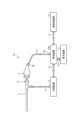
- FIG. 1 is a diagram showing a schematic configuration of an endoscope system according to a first embodiment.
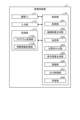
- FIG. 2 is a block diagram showing a functional configuration of a main part of the endoscope system according to the first embodiment.
- FIG. 3 is a diagram illustrating a schematic diagram of wavelength characteristics of light emitted by each of the second light source unit and the third light source unit according to the first embodiment.
- FIG. 4 is a diagram illustrating a schematic configuration of a pixel unit according to the first embodiment.
- FIG. 5 is a diagram illustrating a schematic configuration of a color filter according to the first embodiment.
- FIG. 6 is a diagram illustrating the sensitivity and wavelength band of each filter according to the first embodiment.
- FIG. 1 is a diagram showing a schematic configuration of an endoscope system according to a first embodiment.
- FIG. 2 is a block diagram showing a functional configuration of a main part of the endoscope system according to the first embodiment.
- FIG. 3 is a diagram illustrating a schematic diagram of
- FIG. 7A is a diagram illustrating signal values of R pixels of the image sensor according to the first embodiment.
- FIG. 7B is a diagram illustrating signal values of G pixels of the image sensor according to the first embodiment.
- FIG. 7C is a diagram illustrating a signal value of a B pixel of the image sensor according to the first embodiment.
- FIG. 8 is a diagram illustrating a schematic configuration of the cut filter according to the first embodiment.
- FIG. 9 is a diagram illustrating a transmission characteristic of the cut filter according to the first embodiment.
- FIG. 10 is a diagram illustrating an example of correlation information recorded by the correlation information recording unit according to the first embodiment.
- FIG. 11 is a flowchart showing an outline of the process executed by the control device according to the first embodiment.
- FIG. 12 is a diagram for explaining the relationship between the hierarchical images and cross sections of biological tissue.
- FIG. 13 is a diagram for explaining the relationship between a thermal denaturation image and a cross section of a biological tissue.
- FIG. 14 is a diagram for explaining the relationship between a displayed image and a cross section of a biological tissue.
- FIG. 15 is a diagram showing a schematic configuration of an endoscope system according to the second embodiment.
- FIG. 16 is a block diagram showing a functional configuration of a medical device according to the second embodiment.
- FIG. 1 is a diagram showing a schematic configuration of an endoscope system according to a first embodiment.
- the endoscope system 1 shown in FIG. 1 is used in the medical field, and is a system for observing and treating biological tissue in a subject such as a living body.
- a rigid endoscope system using a rigid endoscope (insertion unit 2) shown in FIG. 1 will be described as the endoscope system 1, but the present invention is not limited to this, and may be, for example, an endoscope system equipped with a flexible endoscope.
- the endoscope system 1 may be applied to a medical microscope or a medical surgery robot system that includes a medical imaging device for imaging a subject and performs surgery or treatment while displaying an observation image based on an imaging signal (image data) captured by the medical imaging device on a display device.
- the endoscope system 1 shown in FIG. 1 is used when performing surgery or treatment on a subject using a treatment tool (not shown) such as an energy device capable of thermal treatment.
- a treatment tool such as an energy device capable of thermal treatment.
- the endoscope system 1 shown in FIG. 1 is used in transurethral resection of bladder tumor (TUR-Bt) and is used when performing treatment on a tumor (bladder cancer) or a lesion area of the bladder.
- the endoscope system 1 shown in FIG. 1 includes an insertion section 2, a light source device 3, a light guide 4, an endoscope camera head 5 (an endoscopic imaging device), a first transmission cable 6, a display device 7, a second transmission cable 8, a control device 9, and a third transmission cable 10.
- the insertion section 2 is hard or at least partially soft and has an elongated shape.
- the insertion section 2 is inserted into a subject such as a patient via a trocar.
- the insertion section 2 is provided with an optical system such as a lens that forms an observation image inside.
- the light source device 3 is connected to one end of the light guide 4, and under the control of the control device 9, supplies illumination light to one end of the light guide 4 to be irradiated into the subject.
- the light source device 3 is realized using one or more light sources, such as an LED (Light Emitting Diode) light source, a xenon lamp, or a semiconductor laser element such as an LD (laser diode), a processor which is a processing device having hardware such as an FPGA (Field Programmable Gate Array) or a CPU (Central Processing Unit), and a memory which is a temporary storage area used by the processor.
- the light source device 3 and the control device 9 may be configured to communicate individually as shown in FIG. 1, or may be integrated.
- One end of the light guide 4 is detachably connected to the light source device 3, and the other end is detachably connected to the insertion section 2.
- the light guide 4 guides the illumination light supplied from the light source device 3 from one end to the other, and supplies it to the insertion section 2.
- the endoscopic camera head 5 is detachably connected to the eyepiece 21 of the insertion section 2. Under the control of the control device 9, the endoscopic camera head 5 receives the observation image formed by the insertion section 2 and performs photoelectric conversion to generate an imaging signal (RAW data), and outputs this imaging signal to the control device 9 via the first transmission cable 6.
- RAW data an imaging signal
- the first transmission cable 6 transmits the imaging signal output from the endoscopic camera head 5 to the control device 9, and also transmits setting data, power, etc. output from the control device 9 to the endoscopic camera head 5.
- the setting data refers to a control signal, synchronization signal, clock signal, etc. that controls the endoscopic camera head 5.
- the display device 7 displays an observation image based on an imaging signal that has been subjected to image processing in the control device 9, and various information related to the endoscope system 1.
- the display device 7 is realized using a display monitor such as a liquid crystal or organic EL (Electro Luminescence) display.
- the second transmission cable 8 transmits the image signal that has been subjected to image processing in the control device 9 to the display device 7.
- the control device 9 is realized using a processor, which is a processing device having hardware such as a GPU (Graphics Processing Unit), FPGA, or CPU, and a memory, which is a temporary storage area used by the processor.
- the control device 9 comprehensively controls the operation of the light source device 3, the endoscopic camera head 5, and the display device 7 via each of the first transmission cable 6, the second transmission cable 8, and the third transmission cable 10 according to a program recorded in the memory.
- the control device 9 also performs various image processing on the imaging signal input via the first transmission cable 6 and outputs it to the second transmission cable 8.
- the control device 9 functions as a medical device.
- the third transmission cable 10 has one end detachably connected to the light source device 3 and the other end detachably connected to the control device 9.
- the third transmission cable 10 transmits control data from the control device 9 to the light source device 3.
- Fig. 2 is a block diagram showing the functional configuration of the main parts of the endoscope system 1.
- the insertion portion 2 has an optical system 22 and an illumination optical system 23.
- the optical system 22 forms an image of the subject by collecting light such as reflected light from the subject, return light from the subject, excitation light from the subject, and fluorescence emitted from a thermally denatured region that has been thermally denatured by a thermal treatment such as an energy device.
- the optical system 22 is realized using one or more lenses, etc.
- the illumination optical system 23 irradiates the subject with illumination light supplied from the light guide 4.
- the illumination optical system 23 is realized using one or more lenses, etc.
- the light source device 3 includes a condenser lens 30, a first light source unit 31, a second light source unit 32, a third light source unit 33, and a light source control unit .
- the focusing lens 30 focuses the light emitted by each of the first light source unit 31, the second light source unit 32, and the third light source unit 33, and emits the light to the light guide 4.
- the first light source unit 31 emits visible white light (normal light) under the control of the light source control unit 34, thereby supplying white light as illumination light to the light guide 4.
- the first light source unit 31 is configured using a collimator lens, a white LED lamp, a driving driver, etc.
- the first light source unit 31 may supply visible white light by simultaneously emitting light using a red LED lamp, a green LED lamp, and a blue LED lamp.
- the first light source unit 31 may also be configured using a halogen lamp, a xenon lamp, etc.
- the second light source unit 32 emits first narrowband light having a predetermined wavelength band under the control of the light source control unit 34, thereby supplying the first narrowband light as illumination light to the light guide 4.
- the first narrowband light has a wavelength band of 530 nm to 550 nm (with a central wavelength of 540 nm).
- the second light source unit 32 is configured using a green LED lamp, a collimating lens, a transmission filter that transmits light of 530 nm to 550 nm, a driver, etc.
- the third light source unit 33 under the control of the light source control unit 34, emits second narrowband light of a wavelength band different from the first narrowband light, thereby supplying the second narrowband light as illumination light to the light guide 4.
- the second narrowband light has a wavelength band of 400 nm to 430 nm (center wavelength 415 nm).
- the third light source unit 33 is realized using a collimating lens, a semiconductor laser such as a violet LD (laser diode), a driving driver, etc.
- the second narrowband light functions as excitation light that excites advanced glycation endproducts generated by applying heat treatment to biological tissue.
- the light source control unit 34 is realized using a processor, which is a processing device having hardware such as an FPGA or a CPU, and a memory, which is a temporary storage area used by the processor.
- the light source control unit 34 controls the light emission timing and light emission time of each of the first light source unit 31, the second light source unit 32, and the third light source unit 33 based on control data input from the control device 9.
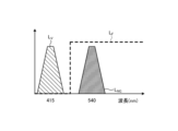
- Fig. 3 is a diagram showing a schematic diagram of the wavelength characteristics of the light emitted by each of the second light source unit 32 and the third light source unit 33.
- the horizontal axis indicates the wavelength (nm), and the vertical axis indicates the wavelength characteristics.
- the broken line L NG indicates the wavelength characteristics of the first narrowband light emitted by the second light source unit 32
- the broken line L V indicates the wavelength characteristics of the second narrowband light (excitation light) emitted by the third light source unit 33.
- the curve L B indicates the blue wavelength band
- the curve L G indicates the green wavelength band
- the curve L R indicates the red wavelength band.
- the second light source unit 32 emits narrowband light having a center wavelength (peak wavelength) of 540 nm and a wavelength band of 530 nm to 550 nm
- the third light source unit 33 emits excitation light having a center wavelength (peak wavelength) of 415 nm and a wavelength band of 400 nm to 430 nm.
- the second light source unit 32 and the third light source unit 33 each emit a first narrowband light and a second narrowband light (excitation light) of mutually different wavelength bands.
- the first narrowband light is used for layer discrimination in biological tissue. Specifically, the first narrowband light increases the difference between the absorbance of the mucosal layer, which is the subject, and the absorbance of the muscle layer, which is the subject, to a degree that makes it possible to distinguish the two subjects. For this reason, in the second image for layer discrimination acquired by irradiating the first narrowband light for layer discrimination, the area in which the mucosal layer is imaged has a smaller pixel value (brightness value) and is darker than the area in which the muscle layer is imaged. That is, in the first embodiment, by using the second image for layer discrimination to generate a display image, it is possible to achieve a display mode in which the mucosal layer and the muscle layer can be easily distinguished.
- the second narrowband light is light for layer discrimination in biological tissue that is different from the first narrowband light.
- the second narrowband light increases the difference in absorbance between the muscle layer, which is the subject, and the fat layer, which is the subject, to a degree that makes it possible to distinguish between the two subjects. Therefore, in the second light image for layer discrimination obtained by irradiating the second narrowband light for layer discrimination, the area in which the muscle layer is imaged has a smaller pixel value (brightness value) and is darker than the area in which the fat layer is imaged. In other words, by using the second image for layer discrimination to generate a display image, it becomes possible to easily distinguish between the muscle layer and the fat layer.
- Both the mucosal layer (biological mucosa) and the muscular layer are subjects that contain a large amount of myoglobin.
- the concentration of myoglobin contained is relatively high in the mucosal layer and relatively low in the muscular layer.
- the difference in the absorption characteristics between the mucosal layer and the muscular layer is caused by the difference in the concentration of myoglobin contained in each of the mucosal layer (biological mucosa) and the muscular layer.
- the difference in absorbance between the mucosal layer and the muscular layer is greatest near the wavelength at which the absorbance of the biological mucosa is at its maximum.
- the first narrowband light for layer discrimination is light that shows a greater difference between the mucosal layer and the muscular layer than light that has a peak wavelength in another wavelength band.
- the second narrowband light for layer discrimination has a lower absorbance of fat compared to the absorbance of the muscle layer
- the pixel value (brightness value) of the area in which the muscle layer is imaged is smaller than the pixel value (brightness value) of the area in which the fat layer is imaged.
- the second narrowband light for layer discrimination is light that corresponds to a wavelength at which the absorbance of the muscle layer is at its maximum, and therefore becomes light that greatly reveals the difference between the muscle layer and the fat layer.
- the difference between the pixel value (brightness value) of the muscle layer area and the pixel value (brightness value) of the fat layer area in the second image for layer discrimination becomes large enough to be distinguished.
- the light source device 3 irradiates the biological tissue with each of the first narrowband light and the second narrowband light. This allows the endoscopic camera head 5, which will be described later, to obtain an image in which the mucosal layer, muscle layer, and fat layer that make up the biological tissue can be identified by capturing the light returned from the biological tissue.
- the second narrowband light excites advanced glycation end products that are generated by subjecting biological tissue to heat treatment by an energy device or the like.
- a glycation reaction Maillard reaction
- the end products resulting from this Maillard reaction are generally called advanced glycation end products (AGEs).
- AGEs are characterized by the inclusion of substances with fluorescent properties.
- biological tissue is heat-treated with an energy device, AGEs are generated by heating amino acids and reducing sugars in the biological tissue and causing a Maillard reaction. The AGEs generated by this heating can be visualized in the state of the heat treatment by fluorescent observation.
- AGEs emit stronger fluorescence than the autofluorescent substances that are originally present in biological tissue.
- the fluorescent properties of AGEs generated in biological tissue by heat treatment by an energy device or the like are utilized to visualize the thermally denatured area caused by the heat treatment.
- the second light source unit 32 excitation light
- the biological tissue with blue excitation light with a wavelength of about 415 nm in order to excite AGEs.
- a fluorescent image (thermal denaturation image) can be observed based on an imaging signal that captures the fluorescence (e.g., green light with a wavelength of 490 to 625 nm) emitted from the thermal denaturation region generated by the AGEs.
- an imaging signal that captures the fluorescence (e.g., green light with a wavelength of 490 to 625 nm) emitted from the thermal denaturation region generated by the AGEs.
- the endoscopic camera head 5 includes an optical system 51, a drive unit 52, an image sensor 53, a cut filter 54, an A/D conversion unit 55, a P/S conversion unit 56, an image capture recording unit 57, and an image capture control unit 58.
- the optical system 51 forms an image of the subject collected by the optical system 22 of the insertion part 2 on the light receiving surface of the image sensor 53.
- the optical system 51 is capable of changing the focal length and focal position.
- the optical system 51 is configured using a plurality of lenses 511.
- the optical system 51 changes the focal length and focal position by moving each of the plurality of lenses 511 on the optical axis L1 using the drive part 52.
- the driving unit 52 moves the multiple lenses 511 of the optical system 51 along the optical axis L1 under the control of the imaging control unit 58.
- the driving unit 52 is configured using a motor such as a stepping motor, a DC motor, or a voice coil motor, and a transmission mechanism such as a gear that transmits the rotation of the motor to the optical system 51.
- the imaging element 53 is realized by using a CCD (Charge Coupled Device) or CMOS (Complementary Metal Oxide Semiconductor) image sensor having multiple pixels arranged in a two-dimensional matrix. Under the control of the imaging control unit 58, the imaging element 53 receives the subject image (light rays) formed by the optical system 51 through the cut filter 54, performs photoelectric conversion to generate an imaging signal (RAW data), and outputs it to the A/D conversion unit 55.
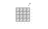
- the imaging element 53 has a pixel unit 531 and a color filter 532.
- Fig. 4 is a diagram showing a schematic configuration of the pixel unit 531.
- the imaging control unit 58 the pixel unit 531 reads out image signals as image data from pixels Pnm in a readout region arbitrarily set as a readout target among the plurality of pixels Pnm , and outputs the image signals to the A/D conversion unit 55.
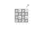
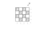
- FIG. 5 is a diagram showing a schematic configuration of color filter 532.
- color filter 532 is configured in a Bayer array with 2 ⁇ 2 as one unit.
- Color filter 532 is configured using a filter R that transmits light in the red wavelength band, two filters G that transmit light in the green wavelength band, and a filter B that transmits light in the blue wavelength band.
- Fig. 6 is a diagram showing the sensitivity and wavelength band of each filter.
- the horizontal axis indicates wavelength (nm) and the vertical axis indicates transmission characteristics (sensitivity characteristics).
- the curve L- B indicates the transmission characteristics of filter B
- the curve L- G indicates the transmission characteristics of filter G
- the curve L- R indicates the transmission characteristics of filter R.
- the filter B transmits light in the blue wavelength band.
- the filter G transmits light in the green wavelength band.
- the filter R transmits light in the red wavelength band.
- the pixel P- nm having the filter R disposed on the light receiving surface is referred to as the R pixel
- the pixel P -nm having the filter G disposed on the light receiving surface is referred to as the G pixel
- the pixel P -nm having the filter B disposed on the light receiving surface is referred to as the B pixel.
- the image sensor 53 configured in this manner receives the subject image formed by the optical system 51, it generates color signals (R signal, G signal, and B signal) for the R pixel, G pixel, and B pixel, respectively, as shown in Figures 7A to 7C.
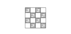
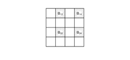
- the cut filter 54 is disposed on the optical axis L1 between the optical system 51 and the image sensor 53.
- the cut filter 54 is provided on the light receiving surface side (incident surface side) of the G pixel provided with the filter G that transmits at least the green wavelength band of the color filter 532.
- the cut filter 54 blocks light in a short wavelength band including the wavelength band of the excitation light and transmits a wavelength band longer than the wavelength band of the excitation light.
- Fig. 8 is a diagram showing a schematic configuration of the cut filter 54. As shown in Fig. 8, the filter F11 constituting the cut filter 54 is disposed at the position where the filter G11 (see Fig. 5) is disposed, on the light receiving surface side directly above the filter G11 .
- Fig. 9 is a diagram showing a schematic diagram of the transmission characteristic of the cut filter 54.
- the horizontal axis indicates wavelength (nm) and the vertical axis indicates the transmission characteristic.
- the broken line L- F indicates the transmission characteristic of the cut filter 54
- the broken line L- NG indicates the wavelength characteristic of the first narrowband light
- the broken line L- V indicates the wavelength characteristic of the second narrowband light (excitation light).
- the cut filter 54 blocks the wavelength band of the second narrowband light (excitation light) and transmits a wavelength band on the longer wavelength side than the wavelength band of the second narrowband light (excitation light). Specifically, the cut filter 54 blocks light in the wavelength band on the shorter wavelength side of 400 nm to less than 430 nm, which includes the wavelength band of the second narrowband light (excitation light), and transmits light in the wavelength band on the longer wavelength side than 400 nm to 430 nm, which includes the second narrowband light (excitation light).
- the A/D conversion unit 55 under the control of the imaging control unit 58, performs A/D conversion processing on the analog imaging signal input from the imaging element 53 and outputs the result to the P/S conversion unit 56.
- the A/D conversion unit 55 is realized using an A/D conversion circuit or the like.
- the P/S conversion unit 56 performs parallel/serial conversion on the digital imaging signal input from the A/D conversion unit 55 under the control of the imaging control unit 58, and outputs the parallel/serial converted imaging signal to the control device 9 via the first transmission cable 6.
- the P/S conversion unit 56 is realized using a P/S conversion circuit or the like. Note that in the first embodiment, instead of the P/S conversion unit 56, an E/O conversion unit that converts the imaging signal into an optical signal may be provided and the imaging signal may be output to the control device 9 by the optical signal, or the imaging signal may be transmitted to the control device 9 by wireless communication such as Wi-Fi (Wireless Fidelity) (registered trademark).
- Wi-Fi Wireless Fidelity
- the imaging and recording unit 57 records various information related to the endoscopic camera head 5 (e.g., pixel information of the imaging element 53, characteristics of the cut filter 54).
- the imaging and recording unit 57 also records various setting data and control parameters transmitted from the control device 9 via the first transmission cable 6.
- the imaging and recording unit 57 is configured using a non-volatile memory and a volatile memory.
- the imaging control unit 58 controls the operation of each of the drive unit 52, the imaging element 53, the A/D conversion unit 55, and the P/S conversion unit 56 based on the setting data received from the control device 9 via the first transmission cable 6.
- the imaging control unit 58 is realized using a TG (Timing Generator), a processor having hardware such as an ASIC (Application Specific Integrated Circuit) or a CPU, and a memory that is a temporary storage area used by the processor.
- the control device 9 includes an S/P conversion unit 91 , an image processing unit 92 , an input unit 93 , a recording unit 94 , and a control unit 95 .
- the S/P conversion unit 91 Under the control of the control unit 95, the S/P conversion unit 91 performs serial/parallel conversion on the image data received from the endoscopic camera head 5 via the first transmission cable 6 and outputs the converted data to the image processing unit 92. If the endoscopic camera head 5 outputs an imaging signal as an optical signal, the S/P conversion unit 91 may be replaced by an O/E conversion unit that converts the optical signal into an electrical signal. If the endoscopic camera head 5 transmits an imaging signal via wireless communication, the S/P conversion unit 91 may be replaced by a communication module capable of receiving wireless signals.
- the image processing unit 92 Under the control of the control unit 95, the image processing unit 92 performs predetermined image processing on the imaging signal of parallel data input from the S/P conversion unit 91 and outputs the result to the display device 7.
- the predetermined image processing includes demosaic processing, white balance processing, gain adjustment processing, gamma correction processing, and format conversion processing.
- the image processing unit 92 is realized using a processor, which is a processing device having hardware such as a GPU or FPGA, and a memory, which is a temporary storage area used by the processor.
- the image processing unit 92 performs image processing on the image signal input from the endoscopic camera head 5 via the S/P conversion unit 91 to generate a white light image.
- the image processing unit 92 performs image processing on the signal values of the G pixels and B pixels included in the image signal input from the endoscopic camera head 5 via the S/P conversion unit 91 to generate a pseudo-color image (narrowband image).
- the signal value of the G pixel contains information on the deep mucosa of the subject.
- the signal value of the B pixel contains information on the surface mucosa of the subject.
- the image processing unit 92 performs image processing such as gain control processing, pixel complementation processing, and mucosa enhancement processing on the signal values of the G pixels and B pixels included in the image signal to generate a pseudo-color image, and outputs this pseudo-color image to the display device 7.
- the pseudo-color image is an image generated using only the signal values of the G pixels and the B pixels. Note that the image processing unit 92 acquires the signal values of the R pixels, but does not use them to generate the pseudo-color image and deletes them.
- the image processing unit 92 performs image processing on the signal values of the G pixels and B pixels contained in the imaging signal input from the endoscopic camera head 5 via the S/P conversion unit 91 to generate a fluorescent image (pseudo color image).
- the signal value of the G pixel contains fluorescent information emitted from the heat treatment area.
- the B pixel contains background information, which is the biological tissue surrounding the heat treatment area.
- the image processing unit 92 performs image processing such as gain control processing, pixel complement processing, and mucosa enhancement processing on the signal values of the G pixels and B pixels contained in the image data to generate a fluorescent image (pseudo color image), and outputs this fluorescent image (pseudo color image) to the display device 7.
- the image processing unit 92 performs gain control processing to make the gain for the signal value of the G pixel larger than the gain for the signal value of the G pixel during normal light observation, while making the gain for the signal value of the B pixel smaller than the gain for the signal value of the B pixel during normal light observation.
- the image processing unit 92 performs gain control processing so that the signal values of the G pixels and the B pixels are the same (1:1).
- the input unit 93 receives inputs of various operations related to the endoscope system 1 and outputs the received operations to the control unit 95.
- the input unit 93 is configured using a mouse, a foot switch, a keyboard, buttons, switches, a touch panel, etc.
- the recording unit 94 is realized using a recording medium such as a volatile memory, a non-volatile memory, an SSD (Solid State Drive), an HDD (Hard Disk Drive), a memory card, etc.
- the recording unit 94 records data including various parameters necessary for the operation of the endoscope system 1.
- the recording unit 94 also has a program recording unit 941 that records various programs for operating the endoscope system 1, and a correlation information recording unit 942 that records correlation information indicating the correlation between the invasiveness (depth) of the thermal treatment to the biological tissue and the luminescence intensity. Details of the correlation information will be described later.
- the control unit 95 is realized using a processor having hardware such as an FPGA or a CPU, and a memory that is a temporary storage area used by the processor.
- the control unit 95 comprehensively controls each component of the endoscope system 1. Specifically, the control unit 95 reads out a program recorded in the program recording unit 941 into a working area of the memory and executes it, and controls each component through the execution of the program by the processor, thereby enabling the hardware and software to work together to realize a functional module that meets a specified purpose.
- the control unit 95 has an acquisition unit 951, a captured image generation unit 952, a determination unit 953, an alignment unit 954, a display image generation unit 955, a recognition unit 956, an output control unit 957, and a learning unit 958.
- the acquisition unit 951 acquires the imaging signal generated by the endoscopic camera head 5 via the S/P conversion unit 91 and the image processing unit 92. Specifically, the acquisition unit 951 acquires a white light imaging signal generated by the endoscopic camera head 5 when the light source device 3 irradiates white light toward biological tissue, a first image signal generated by the endoscopic camera head 5 when the light source device 3 irradiates first narrowband light and second narrowband light toward biological tissue, and a second image signal generated by the endoscopic camera head 5 when the light source device 3 irradiates second narrowband light (excitation light) toward biological tissue.
- the captured image generating unit 952 generates a hierarchical image capable of identifying the mucosal layer, muscle layer, and fat layer in the generated tissue, based on the first image signal and the second image signal acquired by the acquiring unit 951.
- the captured image generating unit 952 also generates a thermal denaturation image, based on the third image signal acquired by the acquiring unit 951.
- the captured image generating unit 952 also generates a white light image, based on the white light image signal acquired by the acquiring unit 951.
- the determination unit 953 determines the depth of thermal denaturation based on the correlation information recorded by the correlation information recording unit 942 and the fluorescence intensity from the thermal denaturation region included in the thermal denaturation image P2.
- the depth is the length from the surface (superficial layer) of the biological tissue toward the fat layer.
- the alignment unit 954 performs alignment processing between the layered images generated by the captured image generation unit 952 and the thermally altered image.
- the display image generating unit 955 generates a display image by combining the hierarchical images and the thermal denaturation image that have been subjected to the alignment process by the alignment unit 954.
- the alignment unit 954 performs alignment processing of the hierarchical images and the thermal denaturation image based on the position where the feature amount of each pixel constituting the hierarchical images and the feature amount of each pixel constituting the thermal denaturation image match.
- the feature amount is, for example, a pixel value, a brightness value, an edge, a contrast, etc.
- the display image generating unit 955 may generate a display image by superimposing the hierarchical images, which are the first image, and the thermal denaturation image, which is the second image, on the white light image generated by the captured image generating unit 952 in a display mode that differs for each layer of the biological tissue in which thermal denaturation has occurred. Furthermore, the display image generating unit 955 may generate a display image that emphasizes the thermal denaturation of a layer selected by the user according to an instruction signal input from the input unit 93 among the layers of the biological tissue in which thermal denaturation has occurred, based on the hierarchical images, which are the first image, and the thermal denaturation image, which is the second image.
- the recognition unit 956 determines the presence or absence of thermal denaturation in a specific layer of the biological tissue based on the hierarchical image, which is the first image, and the thermal denaturation image, which is the second image. Specifically, the recognition unit 956 individually recognizes thermal denaturation in each layer of the mucosa layer, muscle layer, and fat layer that constitute the biological tissue contained in the display image generated by the display image generation unit 955, based on the depth of thermal denaturation determined by the determination unit 953.
- the output control unit 957 outputs support information indicating thermal degeneration to a specific layer based on the determination result (recognition result) of the recognition unit 956 determining whether or not thermal degeneration has occurred. Specifically, the output control unit 957 outputs the thermal degeneration to the display device 7 in a different display mode for each layer based on the display image generated by the display image generation unit 955 and the recognition result of the thermal degeneration to each layer recognized by the recognition unit 956. Furthermore, the output control unit 957 may change the type of display image generated by the display image generation unit 955 based on an instruction signal input from the input unit 93 and output it to the display device 7.
- the output control unit 957 outputs to the display device 7 a display image by superimposing it on the white light image generated by the captured image generation unit 952 in a different display mode for each layer of the biological tissue in which thermal degeneration has occurred, and a display image emphasizing the thermal degeneration to the layer selected by the user, based on the instruction signal input from the input unit 93.
- the learning unit 958 takes as input data a hierarchical image, which is a first image including layer information of biological tissue composed of multiple layers, and a thermal denaturation image, which is a second image including thermal denaturation information related to thermal denaturation due to thermal treatment of biological tissue, and generates a trained model by machine learning using training data in which support information indicating thermal denaturation of a specific layer in the biological tissue is output as output data.
- a hierarchical image which is a first image including layer information of biological tissue composed of multiple layers
- a thermal denaturation image which is a second image including thermal denaturation information related to thermal denaturation due to thermal treatment of biological tissue
- the learning unit 958 may take as input data a fluorescent image obtained by irradiating the biological tissue with excitation light and capturing fluorescence, and a white light image obtained by irradiating the biological tissue with white light, and generate a trained model by machine learning using training data in which support information indicating thermal denaturation of a specific layer in the biological tissue is output as output data.
- the trained model is composed of a neural network in which each layer has one or more nodes.
- the type of machine learning is not particularly limited, but may be, for example, a method in which teacher data and learning data are prepared that correspond to a plurality of hierarchical images and a plurality of thermal denaturation images, and the depth of thermal denaturation or the recognition result of thermal denaturation related to thermal denaturation due to heat treatment that is recognized or annotated from the hierarchical images and the plurality of thermal denaturation images, and the teacher data and learning data are input into a computational model based on a multilayer neural network for learning.
- machine learning techniques that are used include those based on multi-layer neural networks such as CNN (Convolutional Neural Network) and 3D-CNN (Deep Neural Network).
- CNN Convolutional Neural Network
- 3D-CNN Deep Neural Network
- a technique based on a recurrent neural network (RNN) or an extended version of RNN called Long Short-Term Memory units (LSTM) may be used.
- RNN recurrent neural network
- LSTM Long Short-Term Memory units
- a control unit of a learning device other than the control device 4 may execute these functions and generate a trained model.
- the function of the learning unit 958 may be provided in the image processing unit 92.
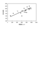
- Fig. 10 is a diagram showing an example of correlation information recorded by the correlation information recording unit 942.
- the vertical axis indicates the emission intensity
- the horizontal axis indicates the invasiveness (depth and area) of the thermal treatment to the biological tissue.
- the line Ly indicates the correlation between the emission intensity and the invasiveness (depth and area) of the thermal treatment to the biological tissue.
- the emission intensity increases as the degree of invasiveness of the thermal treatment to the biological tissue increases.
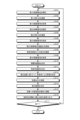
- FIG 11 is a flow chart showing an outline of the process executed by the control device 9.
- control unit 95 controls the light source control unit 34 of the light source device 3 to cause the second light source unit 32 to emit light and supply the first narrowband light to the insertion unit 2, thereby irradiating the first narrowband light toward the biological tissue (step S101).
- control unit 95 controls the imaging control unit 58 to cause the imaging element 53 to capture an image of the first return light from the biological tissue (step S102).
- the acquisition unit 951 acquires a first imaging signal generated by imaging by the imaging element 53 of the endoscopic camera head 5 (step S103).
- control unit 95 controls the light source control unit 34 of the light source device 3 to cause the second light source unit 32 to emit light and supply the second narrowband light to the insertion unit 2, thereby irradiating the second narrowband light toward the biological tissue (step S104).
- the control unit 95 then controls the imaging control unit 58 to cause the imaging element 53 to capture an image of the second return light from the biological tissue (step S105).
- the acquisition unit 951 acquires a second imaging signal generated by imaging by the imaging element 53 of the endoscopic camera head 5 (step S106).
- control unit 95 controls the light source control unit 34 of the light source device 3 to cause the third light source unit 33 to emit light and supply the second narrowband light, which is excitation light, to the insertion unit 2, thereby irradiating the excitation light toward the biological tissue (step S107).
- control unit 95 controls the imaging control unit 58 to cause the imaging element 53 to capture an image of the fluorescence from the thermally denatured region of the biological tissue (step S108).
- the acquisition unit 951 acquires a third imaging signal generated by imaging by the imaging element 53 of the endoscopic camera head 5 (step S109).
- the captured image generating unit 952 generates a hierarchical image that can distinguish the mucosal layer, muscle layer, and fat layer in the generated tissue on a layer-by-layer basis based on the first image signal and the second image signal acquired by the acquiring unit 951 (step S110).
- the control device 9 proceeds to step S111, which will be described later.
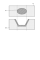
- FIG. 12 is a diagram that illustrates the relationship between the hierarchical images and cross sections of biological tissue.
- the upper row shows the hierarchical image P1
- the lower row shows each layer of the biological tissue.
- the hierarchical image P1 includes an exposed muscle layer region W1 in which the mucosal layer M1 and the muscle layer M2 have been exposed by thermal treatment using an energy device or the like.
- the hierarchical image P1 is in a state in which thermal treatment using an energy device or the like has not yet reached the fat layer M3.
- step S111 the captured image generating section 952 generates a thermal denaturation image based on the third image signal acquired by the acquiring section 951.
- step S112 the control device 9 proceeds to step S112, which will be described later.
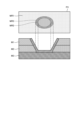
- FIG. 13 is a diagram that illustrates the relationship between a thermal denaturation image and a cross-section of biological tissue.
- the upper part shows a thermal denaturation image P2
- the lower part shows each layer of the biological tissue.
- the thermal denaturation image P2 includes a thermally denatured region W2 that has been caused by thermal treatment using an energy device or the like.
- step S112 the determination unit 953 determines the depth of thermal denaturation based on the correlation information recorded by the correlation information recording unit 942 and the fluorescence intensity from the thermally denatured region included in the thermal denaturation image P2.
- the depth refers to the length from the surface of the biological tissue toward the fat layer.
- the alignment unit 954 performs alignment processing between the hierarchical image P1 and the thermally transformed image P2 (step S113). Specifically, the alignment unit 954 performs alignment processing using well-known techniques so that the positions of the feature amounts contained in the hierarchical image P1 and the feature amounts contained in the thermally transformed image P2 match. For example, the alignment unit 954 performs alignment processing between the hierarchical image P1 and the thermally transformed image P2 based on the positions where the feature amounts of each pixel constituting the hierarchical image P1 and the thermally transformed image P2 match.
- the feature amounts are, for example, pixel values, brightness values, edges, contrast, etc.
- the display image generating unit 955 generates a display image by combining the hierarchical image P1 and the thermally altered image P2 that have been aligned by the alignment unit 954 (step S114).
- the recognition unit 956 recognizes the thermal denaturation of each of the mucosal layer, muscle layer, and fat layer that constitute the biological tissue included in the display image generated by the alignment unit 954 through the alignment process, based on the depth of thermal denaturation determined by the determination unit 953 (step S115). Specifically, the recognition unit 956 recognizes the thermal denaturation of each of the mucosal layer M1, muscle layer M2, and fat layer M3 included in the display image P3, based on the depth of thermal denaturation determined by the determination unit 953. In this case, the recognition unit 956 recognizes the thermal denaturation of each of the mucosal layer M1, muscle layer M2, and fat layer M3 included in the display image P3, based on the depth of thermal denaturation determined by the determination unit 953.
- the output control unit 957 outputs the thermal denaturation to the display device 7 in a different display form for each layer based on the display image generated by the display image generation unit 955 and the recognition result of the thermal denaturation for each layer recognized by the recognition unit 956 (step S116).
- the output control unit 957 outputs the display image P3 to the display device 7 as support information in a different display mode for each layer based on the display image generated by the display image generation unit 955 and the recognition result of the thermal denaturation of each layer recognized by the recognition unit 956. Specifically, the output control unit 957 displays the display areas corresponding to the mucosal layer M1, the muscle layer M2, and the fat layer M3 in "yellow,” "green,” and “blue.” For example, in the case shown in FIG.
- the output control unit 957 displays the thermal denaturation area MR2 of the muscle layer and the thermal denaturation area MR3 of the fat layer in the display image P3 in distinguishable colors, for example, displays the thermal denaturation area of the muscle layer in "green” and displays the thermal denaturation area of the fat layer in "blue,” and outputs the display device 7. This allows the user to intuitively grasp whether or not layers not exposed to the surface have been thermally altered.
- the output control unit 957 distinguishes the display areas corresponding to the mucosal layer M1, the muscle layer M2, and the fat layer M3 by different colors, but this is not limited to this.
- the display areas corresponding to the mucosal layer, the muscle layer, and the fat layer may be output to the display device 7 with the contours of the display areas emphasized for each depth of thermal alteration.
- the output control unit 957 may superimpose the depth of thermal alteration determined by the determination unit 953 on the display image P3 as support information and output it to the display device 7.
- the control unit 95 determines whether or not an end signal to end the observation of the subject by the endoscope system 1 has been input from the input unit 93 (step S117). If the control unit 95 determines that an end signal to end the observation of the subject by the endoscope system 1 has been input from the input unit 93 (step S117: Yes), the control device 9 ends this process. On the other hand, if the control unit 95 determines that an end signal to end the observation of the subject by the endoscope system 1 has not been input from the input unit 93 (step S117: No), the control device 9 returns to step S101 described above.
- the output control unit 957 outputs the display image P3 to the display device 7 as support information, in which the thermal denaturation is displayed in a different manner for each layer, based on the presence or absence of thermal denaturation in each layer of the biological tissue recognized by the recognition unit 956.
- the user can confirm the depth to which the thermal denaturation has penetrated the biological tissue.
- the output control unit 957 may output each layer to the display device 7 in a display mode that differs depending on the depth of thermal denaturation, based on the display image P3 generated by the display image generation unit 955 and the recognition result of the thermal denaturation of each layer recognized by the recognition unit 956.
- the recognition unit 956 recognizes (determines) the thermal denaturation of each of the mucosal layer, muscle layer, and fat layer constituting the biological tissue included in the display image generated by the alignment unit 954 through the alignment process based on the depth of thermal denaturation determined by the determination unit 953, and the output control unit 957 outputs the display image P3 in a display mode to the display device 7 according to the recognition result of the thermal denaturation of each layer recognized by the recognition unit 956. This allows the user to grasp the presence or absence of thermal denaturation of each of the mucosal layer, muscle layer, and fat layer.
- the output control unit 957 may output depth information regarding the depth of thermal denaturation determined by the determination unit 953 as support information.
- the learning unit 958 is provided in the control device 4, but this is not limited thereto, and the learning unit 958 that generates a trained model may be provided in a device different from the control device 4, such as a learning device or a server that can be connected via a network.
- the output control unit 957 may output to the display device 7 a display image generated by the display image generating unit 955 superimposing, in a different display mode for each layer of biological tissue in which thermal denaturation has occurred, on the white light image generated by the captured image generating unit 952. This allows the user to grasp the presence or absence of thermal denaturation in each of the mucosal layer, muscle layer, and fat layer.
- the display image generating unit 955 may generate a display image that emphasizes thermal degeneration in a layer selected by the user according to an instruction signal input from the input unit 93 among the layers of biological tissue in which thermal degeneration has occurred, based on the hierarchical image as the first image and the thermal degeneration image as the second image, and the output control unit 957 may output the display image generated by the display image generating unit 955 to the display device 7. This allows the user to confirm thermal degeneration in the desired layer.
- the control unit 95 of the control device 9 determines the presence or absence of thermal denaturation in a predetermined layer of the biological tissue based on a layer identification image, which is a first image including layer information of a biological tissue having a plurality of layers, and a thermal denaturation image, which is a second image including thermal denaturation information, and outputs support information indicating thermal denaturation in the predetermined layer to the display device 7.
- a medical device that outputs support information is separately provided.
- the configuration of the endoscope system according to the second embodiment will be described below. Note that the same components as those in the endoscope system 1 according to the first embodiment described above are denoted by the same reference numerals, and detailed description thereof will be omitted.
- FIG. 15 is a diagram showing a schematic configuration of an endoscope system according to embodiment 2.
- the endoscope system 1A shown in Fig. 15 includes a control device 9A instead of the control device 9 of the endoscope system 1 according to the above-described embodiment 1.
- the endoscope system 1A further includes a medical device 11 and a fourth transmission cable 12 in addition to the configuration of the endoscope system 1 according to the above-described embodiment 1.
- the control device 9A is realized using a processor, which is a processing device having hardware such as a GPU, FPGA, or CPU, and a memory, which is a temporary storage area used by the processor.
- the control device 9A comprehensively controls the operations of the light source device 3, the endoscopic camera head 5, the display device 7, and the medical device 11 via each of the first transmission cable 6, the second transmission cable 8, the third transmission cable 10, and the fourth transmission cable 12 according to a program recorded in the memory.
- the control device 9A omits the functions of the acquisition unit 951, the captured image generation unit 952, the determination unit 953, the alignment unit 954, the display image generation unit 955, the recognition unit 956, the output control unit 957, and the learning unit 958 from the control unit 95 according to the above-mentioned first embodiment.
- the medical device 11 is realized using a processor, which is a processing device having hardware such as a GPU, FPGA, or CPU, and a memory, which is a temporary storage area used by the processor.
- the medical device 11 acquires various information from the control device 9A via the fourth transmission cable 12, and outputs the acquired various information to the control device 9A.
- the detailed functional configuration of the medical device 11 will be described later.
- the fourth transmission cable 12 has one end detachably connected to the control device 9A and the other end detachably connected to the medical device 11.
- the fourth transmission cable 12 transmits various information from the control device 9A to the medical device 11 and transmits various information from the medical device 11 to the control device 9A.
- Fig. 16 is a block diagram showing the functional configuration of the medical device 11.
- the medical device 11 shown in Fig. 16 includes a communication I/F 111, an input unit 112, a recording unit 113, and a control unit 114.
- the communication I/F 111 is an interface for communicating with the control device 9A via the fourth transmission cable 12.
- the communication I/F 111 receives various information from the control device 9A according to a predetermined communication standard, and outputs the received information to the control unit 114.
- the input unit 112 receives inputs of various operations related to the endoscope system 1A and outputs the received operations to the control unit 114.
- the input unit 112 is configured using a mouse, a foot switch, a keyboard, buttons, switches, a touch panel, etc.
- the recording unit 113 is realized using a recording medium such as a volatile memory, a non-volatile memory, an SSD, an HDD, or a memory card.
- the recording unit 113 records data including various parameters required for the operation of the medical device 11.
- the recording unit 113 also has a program recording unit 113a that records various programs for operating the medical device 11, and a correlation information recording unit 113b that records correlation information indicating the correlation between the invasiveness (depth) of the thermal treatment to the biological tissue and the emission intensity.
- the control unit 114 is realized using a processor having hardware such as an FPGA or a CPU, and a memory that is a temporary storage area used by the processor.
- the control unit 114 comprehensively controls each unit that constitutes the medical device 11.
- the control unit 114 has the same functions as the control unit 95 in the above-mentioned first embodiment. Specifically, the control unit 114 has an acquisition unit 951, a captured image generation unit 952, a determination unit 953, an alignment unit 954, a display image generation unit 955, a recognition unit 956, an output control unit 957, and a learning unit 958.
- the medical device 11 configured in this manner executes the same processing as the control device 9 according to the first embodiment described above, and outputs the processing results to the control device 9A.
- the control device 9A outputs to the display device 7 the display image generated by the image processing unit 92 based on the processing results of the medical device 11, and displays each layer in a different display mode depending on the depth of thermal denaturation based on the recognition results of the thermal denaturation of each layer recognized by the recognition unit 956.
- the second embodiment described above has the same effect as the first embodiment, i.e., the user can check the depth of penetration of the biological tissue by thermal denaturation.
- Various inventions can be formed by appropriately combining multiple components disclosed in the endoscope systems according to the above-mentioned first and second embodiments of the present disclosure. For example, some components may be deleted from all the components described in the endoscope systems according to the above-mentioned embodiments of the present disclosure. Furthermore, the components described in the endoscope systems according to the above-mentioned embodiments of the present disclosure may be appropriately combined.
- the systems are connected to each other by wires, but they may be connected wirelessly via a network.
- the functions of the control unit provided in the endoscope system, and the functional modules of the acquisition unit 951, captured image generation unit 952, decision unit 953, alignment unit 954, display image generation unit 955, recognition unit 956, and output control unit 957 may be provided in a server or the like that can be connected via a network.
- a server may be provided for each functional module.
- transurethral bladder tumor resection an example of use in transurethral bladder tumor resection has been described, but the present disclosure is not limited to this, and can be applied to various procedures, such as resecting lesions using an energy device, etc.
- the "unit” described above can be read as “means” or “circuit.”
- the control unit can be read as control means or control circuit.
Landscapes
- Health & Medical Sciences (AREA)
- Life Sciences & Earth Sciences (AREA)
- Surgery (AREA)
- Engineering & Computer Science (AREA)
- Medical Informatics (AREA)
- Biomedical Technology (AREA)
- Animal Behavior & Ethology (AREA)
- Radiology & Medical Imaging (AREA)
- Optics & Photonics (AREA)
- Nuclear Medicine, Radiotherapy & Molecular Imaging (AREA)
- Physics & Mathematics (AREA)
- Heart & Thoracic Surgery (AREA)
- Biophysics (AREA)
- Molecular Biology (AREA)
- Pathology (AREA)
- General Health & Medical Sciences (AREA)
- Public Health (AREA)
- Veterinary Medicine (AREA)
- Signal Processing (AREA)
- Artificial Intelligence (AREA)
- Evolutionary Computation (AREA)
- Urology & Nephrology (AREA)
- Endoscopes (AREA)
Abstract
Priority Applications (3)
| Application Number | Priority Date | Filing Date | Title |
|---|---|---|---|
| PCT/JP2023/004455 WO2024166328A1 (fr) | 2023-02-09 | 2023-02-09 | Dispositif médical, système médical, dispositif d'apprentissage, procédé d'utilisation de dispositif médical, et programme |
| CN202380093310.XA CN120641021A (zh) | 2023-02-09 | 2023-02-09 | 医疗用装置、医疗用系统、学习装置、医疗用装置的工作方法以及程序 |
| US19/290,902 US20250352028A1 (en) | 2023-02-09 | 2025-08-05 | Medical device, medical system, learning device, method of operating medical device, and computer-readable recording medium |
Applications Claiming Priority (1)
| Application Number | Priority Date | Filing Date | Title |
|---|---|---|---|
| PCT/JP2023/004455 WO2024166328A1 (fr) | 2023-02-09 | 2023-02-09 | Dispositif médical, système médical, dispositif d'apprentissage, procédé d'utilisation de dispositif médical, et programme |
Related Child Applications (1)
| Application Number | Title | Priority Date | Filing Date |
|---|---|---|---|
| US19/290,902 Continuation US20250352028A1 (en) | 2023-02-09 | 2025-08-05 | Medical device, medical system, learning device, method of operating medical device, and computer-readable recording medium |
Publications (1)
| Publication Number | Publication Date |
|---|---|
| WO2024166328A1 true WO2024166328A1 (fr) | 2024-08-15 |
Family
ID=92262158
Family Applications (1)
| Application Number | Title | Priority Date | Filing Date |
|---|---|---|---|
| PCT/JP2023/004455 Ceased WO2024166328A1 (fr) | 2023-02-09 | 2023-02-09 | Dispositif médical, système médical, dispositif d'apprentissage, procédé d'utilisation de dispositif médical, et programme |
Country Status (3)
| Country | Link |
|---|---|
| US (1) | US20250352028A1 (fr) |
| CN (1) | CN120641021A (fr) |
| WO (1) | WO2024166328A1 (fr) |
Citations (8)
| Publication number | Priority date | Publication date | Assignee | Title |
|---|---|---|---|---|
| JPH10505768A (ja) * | 1994-09-14 | 1998-06-09 | シーダーズ − サイナイ メディカル センター | 分光学的熱傷傷害評価のための装置と方法 |
| JP2008537995A (ja) * | 2005-01-20 | 2008-10-02 | ザ リージェンツ オブ ザ ユニバーシティ オブ カリフォルニア | 高分解能空間変調蛍光画像化および断層撮影のための方法ならびに装置 |
| JP2014228409A (ja) * | 2013-05-23 | 2014-12-08 | シャープ株式会社 | 測定用装置 |
| JP2016540558A (ja) * | 2013-11-14 | 2016-12-28 | ザ・ジョージ・ワシントン・ユニバーシティThe George Washingtonuniversity | 蛍光イメージングを用いて損傷の深さを決定するためのシステム及び方法 |
| JP2017513645A (ja) * | 2014-04-28 | 2017-06-01 | カーディオフォーカス,インコーポレーテッド | アブレーション処置の際にicg色素組成物を用いて組織を視覚化するためのシステムおよび方法 |
| JP2017537681A (ja) * | 2014-11-03 | 2017-12-21 | ザ・ジョージ・ワシントン・ユニバーシティThe George Washingtonuniversity | 損傷評価システム及びその方法 |
| WO2019244248A1 (fr) * | 2018-06-19 | 2019-12-26 | オリンパス株式会社 | Endoscope, procédé de fonctionnement d'endoscope, et programme |
| WO2020008527A1 (fr) * | 2018-07-03 | 2020-01-09 | オリンパス株式会社 | Dispositif endoscopique, procédé de fonctionnement du dispositif endoscopique et programme |
-
2023
- 2023-02-09 CN CN202380093310.XA patent/CN120641021A/zh active Pending
- 2023-02-09 WO PCT/JP2023/004455 patent/WO2024166328A1/fr not_active Ceased
-
2025
- 2025-08-05 US US19/290,902 patent/US20250352028A1/en active Pending
Patent Citations (8)
| Publication number | Priority date | Publication date | Assignee | Title |
|---|---|---|---|---|
| JPH10505768A (ja) * | 1994-09-14 | 1998-06-09 | シーダーズ − サイナイ メディカル センター | 分光学的熱傷傷害評価のための装置と方法 |
| JP2008537995A (ja) * | 2005-01-20 | 2008-10-02 | ザ リージェンツ オブ ザ ユニバーシティ オブ カリフォルニア | 高分解能空間変調蛍光画像化および断層撮影のための方法ならびに装置 |
| JP2014228409A (ja) * | 2013-05-23 | 2014-12-08 | シャープ株式会社 | 測定用装置 |
| JP2016540558A (ja) * | 2013-11-14 | 2016-12-28 | ザ・ジョージ・ワシントン・ユニバーシティThe George Washingtonuniversity | 蛍光イメージングを用いて損傷の深さを決定するためのシステム及び方法 |
| JP2017513645A (ja) * | 2014-04-28 | 2017-06-01 | カーディオフォーカス,インコーポレーテッド | アブレーション処置の際にicg色素組成物を用いて組織を視覚化するためのシステムおよび方法 |
| JP2017537681A (ja) * | 2014-11-03 | 2017-12-21 | ザ・ジョージ・ワシントン・ユニバーシティThe George Washingtonuniversity | 損傷評価システム及びその方法 |
| WO2019244248A1 (fr) * | 2018-06-19 | 2019-12-26 | オリンパス株式会社 | Endoscope, procédé de fonctionnement d'endoscope, et programme |
| WO2020008527A1 (fr) * | 2018-07-03 | 2020-01-09 | オリンパス株式会社 | Dispositif endoscopique, procédé de fonctionnement du dispositif endoscopique et programme |
Also Published As
| Publication number | Publication date |
|---|---|
| CN120641021A (zh) | 2025-09-12 |
| US20250352028A1 (en) | 2025-11-20 |
Similar Documents
| Publication | Publication Date | Title |
|---|---|---|
| JP5606120B2 (ja) | 内視鏡装置 | |
| JP5329593B2 (ja) | 生体情報取得システムおよび生体情報取得システムの作動方法 | |
| JP5508959B2 (ja) | 内視鏡装置 | |
| US20230000330A1 (en) | Medical observation system, medical imaging device and imaging method | |
| US20230248209A1 (en) | Assistant device, endoscopic system, assistant method, and computer-readable recording medium | |
| JP6230409B2 (ja) | 内視鏡装置 | |
| JP2021132695A (ja) | 医療用画像処理装置、医療用観察システムおよび画像処理方法 | |
| JP7417712B2 (ja) | 医療用画像処理装置、医療用撮像装置、医療用観察システム、医療用画像処理装置の作動方法およびプログラム | |
| JP2011194082A (ja) | 内視鏡画像補正装置および内視鏡装置 | |
| WO2024166328A1 (fr) | Dispositif médical, système médical, dispositif d'apprentissage, procédé d'utilisation de dispositif médical, et programme | |
| WO2024166310A1 (fr) | Dispositif médical, système médical, dispositif d'apprentissage, procédé d'utilisation de dispositif médical, et programme | |
| WO2024166330A1 (fr) | Dispositif médical, système médical, procédé de fonctionnement de dispositif médical et programme | |
| JP5897663B2 (ja) | 内視鏡装置 | |
| WO2024166308A1 (fr) | Dispositif médical, système médical, dispositif d'apprentissage, procédé d'utilisation de dispositif médical, et programme | |
| WO2024166327A1 (fr) | Dispositif médical, système médical, procédé d'utilisation de dispositif médical, et programme | |
| US20250356490A1 (en) | Assistance device, operation method of assistance device, computer-readable recording medium, medical system, and learning device | |
| WO2024166304A1 (fr) | Dispositif de traitement d'image, système médical, procédé d'utilisation de dispositif de traitement d'image, et dispositif d'apprentissage | |
| WO2024166311A1 (fr) | Dispositif de traitement d'image, système médical, procédé de fonctionnement de dispositif de traitement d'image et dispositif d'apprentissage | |
| WO2024166325A1 (fr) | Dispositif médical, système d'endoscope, procédé de commande, programme de commande et dispositif d'apprentissage | |
| WO2024166309A1 (fr) | Dispositif médical, système d'endoscope, procédé de commande, programme de commande et dispositif d'apprentissage | |
| US20250352026A1 (en) | Medical device, medical system, operation method of medical device, and computer-readable recording medium | |
| US20230210354A1 (en) | Assist device, endoscope system, assist method and computer-readable recording medium | |
| WO2024166306A1 (fr) | Dispositif médical, système d'endoscope, procédé de commande, programme de commande et dispositif d'apprentissage | |
| JP6104419B2 (ja) | 内視鏡装置 |
Legal Events
| Date | Code | Title | Description |
|---|---|---|---|
| 121 | Ep: the epo has been informed by wipo that ep was designated in this application |
Ref document number: 23921159 Country of ref document: EP Kind code of ref document: A1 |
|
| WWE | Wipo information: entry into national phase |
Ref document number: 202380093310.X Country of ref document: CN |
|
| NENP | Non-entry into the national phase |
Ref country code: DE |
|
| WWP | Wipo information: published in national office |
Ref document number: 202380093310.X Country of ref document: CN |
|
| 122 | Ep: pct application non-entry in european phase |
Ref document number: 23921159 Country of ref document: EP Kind code of ref document: A1 |