WO2024166328A1 - Medical device, medical system, learning device, method for operating medical device, and program - Google Patents
Medical device, medical system, learning device, method for operating medical device, and program Download PDFInfo
- Publication number
- WO2024166328A1 WO2024166328A1 PCT/JP2023/004455 JP2023004455W WO2024166328A1 WO 2024166328 A1 WO2024166328 A1 WO 2024166328A1 JP 2023004455 W JP2023004455 W JP 2023004455W WO 2024166328 A1 WO2024166328 A1 WO 2024166328A1
- Authority
- WO
- WIPO (PCT)
- Prior art keywords
- image
- biological tissue
- layer
- thermal denaturation
- light
- Prior art date
- Legal status (The legal status is an assumption and is not a legal conclusion. Google has not performed a legal analysis and makes no representation as to the accuracy of the status listed.)
- Ceased
Links
Images


Classifications
-
- A—HUMAN NECESSITIES
- A61—MEDICAL OR VETERINARY SCIENCE; HYGIENE
- A61B—DIAGNOSIS; SURGERY; IDENTIFICATION
- A61B1/00—Instruments for performing medical examinations of the interior of cavities or tubes of the body by visual or photographical inspection, e.g. endoscopes; Illuminating arrangements therefor
- A61B1/04—Instruments for performing medical examinations of the interior of cavities or tubes of the body by visual or photographical inspection, e.g. endoscopes; Illuminating arrangements therefor combined with photographic or television appliances
- A61B1/045—Control thereof
-
- A—HUMAN NECESSITIES
- A61—MEDICAL OR VETERINARY SCIENCE; HYGIENE
- A61B—DIAGNOSIS; SURGERY; IDENTIFICATION
- A61B1/00—Instruments for performing medical examinations of the interior of cavities or tubes of the body by visual or photographical inspection, e.g. endoscopes; Illuminating arrangements therefor
- A61B1/00002—Operational features of endoscopes
- A61B1/00004—Operational features of endoscopes characterised by electronic signal processing
- A61B1/00009—Operational features of endoscopes characterised by electronic signal processing of image signals during a use of endoscope
- A61B1/000094—Operational features of endoscopes characterised by electronic signal processing of image signals during a use of endoscope extracting biological structures
-
- A—HUMAN NECESSITIES
- A61—MEDICAL OR VETERINARY SCIENCE; HYGIENE
- A61B—DIAGNOSIS; SURGERY; IDENTIFICATION
- A61B1/00—Instruments for performing medical examinations of the interior of cavities or tubes of the body by visual or photographical inspection, e.g. endoscopes; Illuminating arrangements therefor
- A61B1/00002—Operational features of endoscopes
- A61B1/00004—Operational features of endoscopes characterised by electronic signal processing
- A61B1/00009—Operational features of endoscopes characterised by electronic signal processing of image signals during a use of endoscope
- A61B1/000096—Operational features of endoscopes characterised by electronic signal processing of image signals during a use of endoscope using artificial intelligence
-
- A—HUMAN NECESSITIES
- A61—MEDICAL OR VETERINARY SCIENCE; HYGIENE
- A61B—DIAGNOSIS; SURGERY; IDENTIFICATION
- A61B1/00—Instruments for performing medical examinations of the interior of cavities or tubes of the body by visual or photographical inspection, e.g. endoscopes; Illuminating arrangements therefor
- A61B1/00002—Operational features of endoscopes
- A61B1/00043—Operational features of endoscopes provided with output arrangements
- A61B1/00045—Display arrangement
- A61B1/0005—Display arrangement combining images e.g. side-by-side, superimposed or tiled
-
- A—HUMAN NECESSITIES
- A61—MEDICAL OR VETERINARY SCIENCE; HYGIENE
- A61B—DIAGNOSIS; SURGERY; IDENTIFICATION
- A61B1/00—Instruments for performing medical examinations of the interior of cavities or tubes of the body by visual or photographical inspection, e.g. endoscopes; Illuminating arrangements therefor
- A61B1/04—Instruments for performing medical examinations of the interior of cavities or tubes of the body by visual or photographical inspection, e.g. endoscopes; Illuminating arrangements therefor combined with photographic or television appliances
- A61B1/043—Instruments for performing medical examinations of the interior of cavities or tubes of the body by visual or photographical inspection, e.g. endoscopes; Illuminating arrangements therefor combined with photographic or television appliances for fluorescence imaging
-
- A—HUMAN NECESSITIES
- A61—MEDICAL OR VETERINARY SCIENCE; HYGIENE
- A61B—DIAGNOSIS; SURGERY; IDENTIFICATION
- A61B1/00—Instruments for performing medical examinations of the interior of cavities or tubes of the body by visual or photographical inspection, e.g. endoscopes; Illuminating arrangements therefor
- A61B1/06—Instruments for performing medical examinations of the interior of cavities or tubes of the body by visual or photographical inspection, e.g. endoscopes; Illuminating arrangements therefor with illuminating arrangements
- A61B1/0638—Instruments for performing medical examinations of the interior of cavities or tubes of the body by visual or photographical inspection, e.g. endoscopes; Illuminating arrangements therefor with illuminating arrangements providing two or more wavelengths
-
- A—HUMAN NECESSITIES
- A61—MEDICAL OR VETERINARY SCIENCE; HYGIENE
- A61B—DIAGNOSIS; SURGERY; IDENTIFICATION
- A61B1/00—Instruments for performing medical examinations of the interior of cavities or tubes of the body by visual or photographical inspection, e.g. endoscopes; Illuminating arrangements therefor
- A61B1/307—Instruments for performing medical examinations of the interior of cavities or tubes of the body by visual or photographical inspection, e.g. endoscopes; Illuminating arrangements therefor for the urinary organs, e.g. urethroscopes, cystoscopes
Definitions
- This disclosure relates to a medical device, a medical system, a learning device, and a method and program for operating a medical device.
- transurethral resection of bladder tumor transurethral resection of bladder tumor: TUR-Bt
- a surgical endoscope resectoscope
- the surgeon uses a resection treatment tool such as an energy device to resect the tumor by scraping it from the surface of the tumor.
- the bladder wall is composed of three layers: the mucosal layer, the muscle layer, and the fat layer. For this reason, users such as doctors and surgeons perform transurethral resection of bladder tumor while distinguishing between the mucosal layer, the muscle layer, and the fat layer.
- a first light having a peak wavelength in a first wavelength range including the wavelength at which the absorbance of the biological mucosa is at its maximum value and a second light having a peak wavelength in a second wavelength range including the wavelength at which the absorbance of the muscle layer is at its maximum value and in which the absorbance of fat is lower than that of the muscle layer are irradiated onto biological tissue, and an image in which each of the mucosal layer, muscle layer, and fat layer can be distinguished is generated using a first image and a second image obtained by capturing the return light from the biological tissue.
- Patent Document 1 Although the user can determine from the image whether or not a layer is exposed after resection, no consideration is given to the depth of penetration of biological tissue due to thermal denaturation using the resection treatment tool. For this reason, there is a demand for technology that allows users to check the depth of penetration of biological tissue due to thermal denaturation.
- the present disclosure has been made in consideration of the above, and aims to provide a medical device, a medical system, a learning device, a method for operating a medical device, and a program that can confirm the depth of penetration of biological tissue by thermal denaturation.
- the medical device disclosed herein is a medical device equipped with a processor, and the processor acquires a first image including layer information of biological tissue composed of multiple layers and a second image including thermal denaturation information related to thermal denaturation caused by thermal treatment of the biological tissue, and determines the presence or absence of thermal denaturation in a specific layer of the biological tissue based on the first image and the second image, and outputs support information indicating thermal denaturation in the specific layer based on the determination result of the presence or absence of the thermal denaturation.
- the layer information includes information about the fat layer in the biological tissue.
- the layer information includes information about layers in the biological tissue.
- the second image is a fluorescence image.
- the processor acquires correlation information indicating the relationship between a preset emission intensity and the depth from the surface due to thermal denaturation, determines the depth from the surface in the biological tissue based on the emission intensity of the fluorescent image and the correlation information, and outputs depth information relating to the depth from the surface in the biological tissue as support information.
- the processor determines the presence or absence of thermal denaturation of the fat layer in the biological tissue based on the first image and the second image.
- the processor generates a display image in which the display mode differs for each layer of the biological tissue in which thermal denaturation has occurred based on the first image and the second image, and outputs the display image.
- the processor acquires a white light image of the biological tissue irradiated with white light, generates the display image by superimposing on the white light image in a different display mode for each layer of the biological tissue in which thermal denaturation has occurred, and outputs the display image.
- the processor generates a third image including information about the muscle layer in the biological tissue.
- the third image includes information about the mucosal layer in the biological tissue.
- the processor generates a display image that emphasizes thermal degeneration in a layer selected by a user from among the layers of the biological tissue in which thermal degeneration is occurring, based on the first image and the second image, and outputs the display image.
- the medical system is a medical system including a light source device, an imaging device, and a medical device, the light source device having a first light source that generates light capable of acquiring layer information of a biological tissue composed of multiple layers, and a second light source that generates excitation light that excites advanced glycation endproducts generated by applying heat treatment to the biological tissue, the imaging device having an imaging element that generates an imaging signal by imaging return light or light emitted from the biological tissue irradiated with the light or the excitation light, the medical device having a processor, the processor generates a first image including layer information of the biological tissue composed of multiple layers based on the imaging signal generated by the imaging element by imaging the return light, generates a second image including thermal denaturation information regarding thermal denaturation caused by the thermal treatment of the biological tissue based on the imaging signal generated by the imaging element by imaging the light emitted, determines the presence or absence of thermal denaturation in a predetermined layer of the biological tissue based on the first image and the second image,
- the learning device is a learning device equipped with a processor, which generates a trained model by machine learning using training data in which a first image including layer information of biological tissue composed of multiple layers and a second image including thermal denaturation information related to thermal denaturation caused by heat treatment of the biological tissue are input data, and support information indicating thermal denaturation of a specific layer in the biological tissue is output data.
- the method of operating a medical device is a method of operating a medical device including a processor, in which the processor acquires a first image including layer information of biological tissue composed of multiple layers and a second image including thermal denaturation information related to thermal denaturation caused by thermal treatment of the biological tissue, determines the presence or absence of thermal denaturation in a specific layer of the biological tissue based on the first image and the second image, and outputs support information indicating thermal denaturation in the specific layer based on the determination result of the presence or absence of the thermal denaturation.
- the program according to the present disclosure is a program executed by a medical device having a processor, and causes the processor to acquire a first image including layer information of biological tissue composed of multiple layers and a second image including thermal denaturation information related to thermal denaturation caused by thermal treatment of the biological tissue, determine the presence or absence of thermal denaturation in a specific layer of the biological tissue based on the first image and the second image, and output support information indicating thermal denaturation in the specific layer based on the determination result of the presence or absence of the thermal denaturation.
- the present disclosure has the effect of making it possible to confirm the depth to which thermal denaturation has penetrated biological tissue.
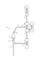
- FIG. 1 is a diagram showing a schematic configuration of an endoscope system according to a first embodiment.
- FIG. 2 is a block diagram showing a functional configuration of a main part of the endoscope system according to the first embodiment.
- FIG. 3 is a diagram illustrating a schematic diagram of wavelength characteristics of light emitted by each of the second light source unit and the third light source unit according to the first embodiment.
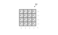
- FIG. 4 is a diagram illustrating a schematic configuration of a pixel unit according to the first embodiment.
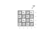
- FIG. 5 is a diagram illustrating a schematic configuration of a color filter according to the first embodiment.
- FIG. 6 is a diagram illustrating the sensitivity and wavelength band of each filter according to the first embodiment.
- FIG. 1 is a diagram showing a schematic configuration of an endoscope system according to a first embodiment.
- FIG. 2 is a block diagram showing a functional configuration of a main part of the endoscope system according to the first embodiment.
- FIG. 3 is a diagram illustrating a schematic diagram of
- FIG. 7A is a diagram illustrating signal values of R pixels of the image sensor according to the first embodiment.
- FIG. 7B is a diagram illustrating signal values of G pixels of the image sensor according to the first embodiment.
- FIG. 7C is a diagram illustrating a signal value of a B pixel of the image sensor according to the first embodiment.
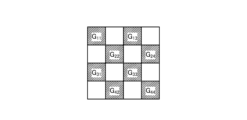
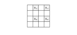
- FIG. 8 is a diagram illustrating a schematic configuration of the cut filter according to the first embodiment.
- FIG. 9 is a diagram illustrating a transmission characteristic of the cut filter according to the first embodiment.
- FIG. 10 is a diagram illustrating an example of correlation information recorded by the correlation information recording unit according to the first embodiment.
- FIG. 11 is a flowchart showing an outline of the process executed by the control device according to the first embodiment.
- FIG. 12 is a diagram for explaining the relationship between the hierarchical images and cross sections of biological tissue.
- FIG. 13 is a diagram for explaining the relationship between a thermal denaturation image and a cross section of a biological tissue.
- FIG. 14 is a diagram for explaining the relationship between a displayed image and a cross section of a biological tissue.
- FIG. 15 is a diagram showing a schematic configuration of an endoscope system according to the second embodiment.
- FIG. 16 is a block diagram showing a functional configuration of a medical device according to the second embodiment.
- FIG. 1 is a diagram showing a schematic configuration of an endoscope system according to a first embodiment.
- the endoscope system 1 shown in FIG. 1 is used in the medical field, and is a system for observing and treating biological tissue in a subject such as a living body.
- a rigid endoscope system using a rigid endoscope (insertion unit 2) shown in FIG. 1 will be described as the endoscope system 1, but the present invention is not limited to this, and may be, for example, an endoscope system equipped with a flexible endoscope.
- the endoscope system 1 may be applied to a medical microscope or a medical surgery robot system that includes a medical imaging device for imaging a subject and performs surgery or treatment while displaying an observation image based on an imaging signal (image data) captured by the medical imaging device on a display device.
- the endoscope system 1 shown in FIG. 1 is used when performing surgery or treatment on a subject using a treatment tool (not shown) such as an energy device capable of thermal treatment.
- a treatment tool such as an energy device capable of thermal treatment.
- the endoscope system 1 shown in FIG. 1 is used in transurethral resection of bladder tumor (TUR-Bt) and is used when performing treatment on a tumor (bladder cancer) or a lesion area of the bladder.
- the endoscope system 1 shown in FIG. 1 includes an insertion section 2, a light source device 3, a light guide 4, an endoscope camera head 5 (an endoscopic imaging device), a first transmission cable 6, a display device 7, a second transmission cable 8, a control device 9, and a third transmission cable 10.
- the insertion section 2 is hard or at least partially soft and has an elongated shape.
- the insertion section 2 is inserted into a subject such as a patient via a trocar.
- the insertion section 2 is provided with an optical system such as a lens that forms an observation image inside.
- the light source device 3 is connected to one end of the light guide 4, and under the control of the control device 9, supplies illumination light to one end of the light guide 4 to be irradiated into the subject.
- the light source device 3 is realized using one or more light sources, such as an LED (Light Emitting Diode) light source, a xenon lamp, or a semiconductor laser element such as an LD (laser diode), a processor which is a processing device having hardware such as an FPGA (Field Programmable Gate Array) or a CPU (Central Processing Unit), and a memory which is a temporary storage area used by the processor.
- the light source device 3 and the control device 9 may be configured to communicate individually as shown in FIG. 1, or may be integrated.
- One end of the light guide 4 is detachably connected to the light source device 3, and the other end is detachably connected to the insertion section 2.
- the light guide 4 guides the illumination light supplied from the light source device 3 from one end to the other, and supplies it to the insertion section 2.
- the endoscopic camera head 5 is detachably connected to the eyepiece 21 of the insertion section 2. Under the control of the control device 9, the endoscopic camera head 5 receives the observation image formed by the insertion section 2 and performs photoelectric conversion to generate an imaging signal (RAW data), and outputs this imaging signal to the control device 9 via the first transmission cable 6.
- RAW data an imaging signal
- the first transmission cable 6 transmits the imaging signal output from the endoscopic camera head 5 to the control device 9, and also transmits setting data, power, etc. output from the control device 9 to the endoscopic camera head 5.
- the setting data refers to a control signal, synchronization signal, clock signal, etc. that controls the endoscopic camera head 5.
- the display device 7 displays an observation image based on an imaging signal that has been subjected to image processing in the control device 9, and various information related to the endoscope system 1.
- the display device 7 is realized using a display monitor such as a liquid crystal or organic EL (Electro Luminescence) display.
- the second transmission cable 8 transmits the image signal that has been subjected to image processing in the control device 9 to the display device 7.
- the control device 9 is realized using a processor, which is a processing device having hardware such as a GPU (Graphics Processing Unit), FPGA, or CPU, and a memory, which is a temporary storage area used by the processor.
- the control device 9 comprehensively controls the operation of the light source device 3, the endoscopic camera head 5, and the display device 7 via each of the first transmission cable 6, the second transmission cable 8, and the third transmission cable 10 according to a program recorded in the memory.
- the control device 9 also performs various image processing on the imaging signal input via the first transmission cable 6 and outputs it to the second transmission cable 8.
- the control device 9 functions as a medical device.
- the third transmission cable 10 has one end detachably connected to the light source device 3 and the other end detachably connected to the control device 9.
- the third transmission cable 10 transmits control data from the control device 9 to the light source device 3.
- Fig. 2 is a block diagram showing the functional configuration of the main parts of the endoscope system 1.
- the insertion portion 2 has an optical system 22 and an illumination optical system 23.
- the optical system 22 forms an image of the subject by collecting light such as reflected light from the subject, return light from the subject, excitation light from the subject, and fluorescence emitted from a thermally denatured region that has been thermally denatured by a thermal treatment such as an energy device.
- the optical system 22 is realized using one or more lenses, etc.
- the illumination optical system 23 irradiates the subject with illumination light supplied from the light guide 4.
- the illumination optical system 23 is realized using one or more lenses, etc.
- the light source device 3 includes a condenser lens 30, a first light source unit 31, a second light source unit 32, a third light source unit 33, and a light source control unit .
- the focusing lens 30 focuses the light emitted by each of the first light source unit 31, the second light source unit 32, and the third light source unit 33, and emits the light to the light guide 4.
- the first light source unit 31 emits visible white light (normal light) under the control of the light source control unit 34, thereby supplying white light as illumination light to the light guide 4.
- the first light source unit 31 is configured using a collimator lens, a white LED lamp, a driving driver, etc.
- the first light source unit 31 may supply visible white light by simultaneously emitting light using a red LED lamp, a green LED lamp, and a blue LED lamp.
- the first light source unit 31 may also be configured using a halogen lamp, a xenon lamp, etc.
- the second light source unit 32 emits first narrowband light having a predetermined wavelength band under the control of the light source control unit 34, thereby supplying the first narrowband light as illumination light to the light guide 4.
- the first narrowband light has a wavelength band of 530 nm to 550 nm (with a central wavelength of 540 nm).
- the second light source unit 32 is configured using a green LED lamp, a collimating lens, a transmission filter that transmits light of 530 nm to 550 nm, a driver, etc.
- the third light source unit 33 under the control of the light source control unit 34, emits second narrowband light of a wavelength band different from the first narrowband light, thereby supplying the second narrowband light as illumination light to the light guide 4.
- the second narrowband light has a wavelength band of 400 nm to 430 nm (center wavelength 415 nm).
- the third light source unit 33 is realized using a collimating lens, a semiconductor laser such as a violet LD (laser diode), a driving driver, etc.
- the second narrowband light functions as excitation light that excites advanced glycation endproducts generated by applying heat treatment to biological tissue.
- the light source control unit 34 is realized using a processor, which is a processing device having hardware such as an FPGA or a CPU, and a memory, which is a temporary storage area used by the processor.
- the light source control unit 34 controls the light emission timing and light emission time of each of the first light source unit 31, the second light source unit 32, and the third light source unit 33 based on control data input from the control device 9.
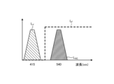
- Fig. 3 is a diagram showing a schematic diagram of the wavelength characteristics of the light emitted by each of the second light source unit 32 and the third light source unit 33.
- the horizontal axis indicates the wavelength (nm), and the vertical axis indicates the wavelength characteristics.
- the broken line L NG indicates the wavelength characteristics of the first narrowband light emitted by the second light source unit 32
- the broken line L V indicates the wavelength characteristics of the second narrowband light (excitation light) emitted by the third light source unit 33.
- the curve L B indicates the blue wavelength band
- the curve L G indicates the green wavelength band
- the curve L R indicates the red wavelength band.
- the second light source unit 32 emits narrowband light having a center wavelength (peak wavelength) of 540 nm and a wavelength band of 530 nm to 550 nm
- the third light source unit 33 emits excitation light having a center wavelength (peak wavelength) of 415 nm and a wavelength band of 400 nm to 430 nm.
- the second light source unit 32 and the third light source unit 33 each emit a first narrowband light and a second narrowband light (excitation light) of mutually different wavelength bands.
- the first narrowband light is used for layer discrimination in biological tissue. Specifically, the first narrowband light increases the difference between the absorbance of the mucosal layer, which is the subject, and the absorbance of the muscle layer, which is the subject, to a degree that makes it possible to distinguish the two subjects. For this reason, in the second image for layer discrimination acquired by irradiating the first narrowband light for layer discrimination, the area in which the mucosal layer is imaged has a smaller pixel value (brightness value) and is darker than the area in which the muscle layer is imaged. That is, in the first embodiment, by using the second image for layer discrimination to generate a display image, it is possible to achieve a display mode in which the mucosal layer and the muscle layer can be easily distinguished.
- the second narrowband light is light for layer discrimination in biological tissue that is different from the first narrowband light.
- the second narrowband light increases the difference in absorbance between the muscle layer, which is the subject, and the fat layer, which is the subject, to a degree that makes it possible to distinguish between the two subjects. Therefore, in the second light image for layer discrimination obtained by irradiating the second narrowband light for layer discrimination, the area in which the muscle layer is imaged has a smaller pixel value (brightness value) and is darker than the area in which the fat layer is imaged. In other words, by using the second image for layer discrimination to generate a display image, it becomes possible to easily distinguish between the muscle layer and the fat layer.
- Both the mucosal layer (biological mucosa) and the muscular layer are subjects that contain a large amount of myoglobin.
- the concentration of myoglobin contained is relatively high in the mucosal layer and relatively low in the muscular layer.
- the difference in the absorption characteristics between the mucosal layer and the muscular layer is caused by the difference in the concentration of myoglobin contained in each of the mucosal layer (biological mucosa) and the muscular layer.
- the difference in absorbance between the mucosal layer and the muscular layer is greatest near the wavelength at which the absorbance of the biological mucosa is at its maximum.
- the first narrowband light for layer discrimination is light that shows a greater difference between the mucosal layer and the muscular layer than light that has a peak wavelength in another wavelength band.
- the second narrowband light for layer discrimination has a lower absorbance of fat compared to the absorbance of the muscle layer
- the pixel value (brightness value) of the area in which the muscle layer is imaged is smaller than the pixel value (brightness value) of the area in which the fat layer is imaged.
- the second narrowband light for layer discrimination is light that corresponds to a wavelength at which the absorbance of the muscle layer is at its maximum, and therefore becomes light that greatly reveals the difference between the muscle layer and the fat layer.
- the difference between the pixel value (brightness value) of the muscle layer area and the pixel value (brightness value) of the fat layer area in the second image for layer discrimination becomes large enough to be distinguished.
- the light source device 3 irradiates the biological tissue with each of the first narrowband light and the second narrowband light. This allows the endoscopic camera head 5, which will be described later, to obtain an image in which the mucosal layer, muscle layer, and fat layer that make up the biological tissue can be identified by capturing the light returned from the biological tissue.
- the second narrowband light excites advanced glycation end products that are generated by subjecting biological tissue to heat treatment by an energy device or the like.
- a glycation reaction Maillard reaction
- the end products resulting from this Maillard reaction are generally called advanced glycation end products (AGEs).
- AGEs are characterized by the inclusion of substances with fluorescent properties.
- biological tissue is heat-treated with an energy device, AGEs are generated by heating amino acids and reducing sugars in the biological tissue and causing a Maillard reaction. The AGEs generated by this heating can be visualized in the state of the heat treatment by fluorescent observation.
- AGEs emit stronger fluorescence than the autofluorescent substances that are originally present in biological tissue.
- the fluorescent properties of AGEs generated in biological tissue by heat treatment by an energy device or the like are utilized to visualize the thermally denatured area caused by the heat treatment.
- the second light source unit 32 excitation light
- the biological tissue with blue excitation light with a wavelength of about 415 nm in order to excite AGEs.
- a fluorescent image (thermal denaturation image) can be observed based on an imaging signal that captures the fluorescence (e.g., green light with a wavelength of 490 to 625 nm) emitted from the thermal denaturation region generated by the AGEs.
- an imaging signal that captures the fluorescence (e.g., green light with a wavelength of 490 to 625 nm) emitted from the thermal denaturation region generated by the AGEs.
- the endoscopic camera head 5 includes an optical system 51, a drive unit 52, an image sensor 53, a cut filter 54, an A/D conversion unit 55, a P/S conversion unit 56, an image capture recording unit 57, and an image capture control unit 58.
- the optical system 51 forms an image of the subject collected by the optical system 22 of the insertion part 2 on the light receiving surface of the image sensor 53.
- the optical system 51 is capable of changing the focal length and focal position.
- the optical system 51 is configured using a plurality of lenses 511.
- the optical system 51 changes the focal length and focal position by moving each of the plurality of lenses 511 on the optical axis L1 using the drive part 52.
- the driving unit 52 moves the multiple lenses 511 of the optical system 51 along the optical axis L1 under the control of the imaging control unit 58.
- the driving unit 52 is configured using a motor such as a stepping motor, a DC motor, or a voice coil motor, and a transmission mechanism such as a gear that transmits the rotation of the motor to the optical system 51.
- the imaging element 53 is realized by using a CCD (Charge Coupled Device) or CMOS (Complementary Metal Oxide Semiconductor) image sensor having multiple pixels arranged in a two-dimensional matrix. Under the control of the imaging control unit 58, the imaging element 53 receives the subject image (light rays) formed by the optical system 51 through the cut filter 54, performs photoelectric conversion to generate an imaging signal (RAW data), and outputs it to the A/D conversion unit 55.
- the imaging element 53 has a pixel unit 531 and a color filter 532.
- Fig. 4 is a diagram showing a schematic configuration of the pixel unit 531.
- the imaging control unit 58 the pixel unit 531 reads out image signals as image data from pixels Pnm in a readout region arbitrarily set as a readout target among the plurality of pixels Pnm , and outputs the image signals to the A/D conversion unit 55.
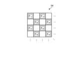
- FIG. 5 is a diagram showing a schematic configuration of color filter 532.
- color filter 532 is configured in a Bayer array with 2 ⁇ 2 as one unit.
- Color filter 532 is configured using a filter R that transmits light in the red wavelength band, two filters G that transmit light in the green wavelength band, and a filter B that transmits light in the blue wavelength band.
- Fig. 6 is a diagram showing the sensitivity and wavelength band of each filter.
- the horizontal axis indicates wavelength (nm) and the vertical axis indicates transmission characteristics (sensitivity characteristics).
- the curve L- B indicates the transmission characteristics of filter B
- the curve L- G indicates the transmission characteristics of filter G
- the curve L- R indicates the transmission characteristics of filter R.
- the filter B transmits light in the blue wavelength band.
- the filter G transmits light in the green wavelength band.
- the filter R transmits light in the red wavelength band.
- the pixel P- nm having the filter R disposed on the light receiving surface is referred to as the R pixel
- the pixel P -nm having the filter G disposed on the light receiving surface is referred to as the G pixel
- the pixel P -nm having the filter B disposed on the light receiving surface is referred to as the B pixel.
- the image sensor 53 configured in this manner receives the subject image formed by the optical system 51, it generates color signals (R signal, G signal, and B signal) for the R pixel, G pixel, and B pixel, respectively, as shown in Figures 7A to 7C.
- the cut filter 54 is disposed on the optical axis L1 between the optical system 51 and the image sensor 53.
- the cut filter 54 is provided on the light receiving surface side (incident surface side) of the G pixel provided with the filter G that transmits at least the green wavelength band of the color filter 532.
- the cut filter 54 blocks light in a short wavelength band including the wavelength band of the excitation light and transmits a wavelength band longer than the wavelength band of the excitation light.
- Fig. 8 is a diagram showing a schematic configuration of the cut filter 54. As shown in Fig. 8, the filter F11 constituting the cut filter 54 is disposed at the position where the filter G11 (see Fig. 5) is disposed, on the light receiving surface side directly above the filter G11 .
- Fig. 9 is a diagram showing a schematic diagram of the transmission characteristic of the cut filter 54.
- the horizontal axis indicates wavelength (nm) and the vertical axis indicates the transmission characteristic.
- the broken line L- F indicates the transmission characteristic of the cut filter 54
- the broken line L- NG indicates the wavelength characteristic of the first narrowband light
- the broken line L- V indicates the wavelength characteristic of the second narrowband light (excitation light).
- the cut filter 54 blocks the wavelength band of the second narrowband light (excitation light) and transmits a wavelength band on the longer wavelength side than the wavelength band of the second narrowband light (excitation light). Specifically, the cut filter 54 blocks light in the wavelength band on the shorter wavelength side of 400 nm to less than 430 nm, which includes the wavelength band of the second narrowband light (excitation light), and transmits light in the wavelength band on the longer wavelength side than 400 nm to 430 nm, which includes the second narrowband light (excitation light).
- the A/D conversion unit 55 under the control of the imaging control unit 58, performs A/D conversion processing on the analog imaging signal input from the imaging element 53 and outputs the result to the P/S conversion unit 56.
- the A/D conversion unit 55 is realized using an A/D conversion circuit or the like.
- the P/S conversion unit 56 performs parallel/serial conversion on the digital imaging signal input from the A/D conversion unit 55 under the control of the imaging control unit 58, and outputs the parallel/serial converted imaging signal to the control device 9 via the first transmission cable 6.
- the P/S conversion unit 56 is realized using a P/S conversion circuit or the like. Note that in the first embodiment, instead of the P/S conversion unit 56, an E/O conversion unit that converts the imaging signal into an optical signal may be provided and the imaging signal may be output to the control device 9 by the optical signal, or the imaging signal may be transmitted to the control device 9 by wireless communication such as Wi-Fi (Wireless Fidelity) (registered trademark).
- Wi-Fi Wireless Fidelity
- the imaging and recording unit 57 records various information related to the endoscopic camera head 5 (e.g., pixel information of the imaging element 53, characteristics of the cut filter 54).
- the imaging and recording unit 57 also records various setting data and control parameters transmitted from the control device 9 via the first transmission cable 6.
- the imaging and recording unit 57 is configured using a non-volatile memory and a volatile memory.
- the imaging control unit 58 controls the operation of each of the drive unit 52, the imaging element 53, the A/D conversion unit 55, and the P/S conversion unit 56 based on the setting data received from the control device 9 via the first transmission cable 6.
- the imaging control unit 58 is realized using a TG (Timing Generator), a processor having hardware such as an ASIC (Application Specific Integrated Circuit) or a CPU, and a memory that is a temporary storage area used by the processor.
- the control device 9 includes an S/P conversion unit 91 , an image processing unit 92 , an input unit 93 , a recording unit 94 , and a control unit 95 .
- the S/P conversion unit 91 Under the control of the control unit 95, the S/P conversion unit 91 performs serial/parallel conversion on the image data received from the endoscopic camera head 5 via the first transmission cable 6 and outputs the converted data to the image processing unit 92. If the endoscopic camera head 5 outputs an imaging signal as an optical signal, the S/P conversion unit 91 may be replaced by an O/E conversion unit that converts the optical signal into an electrical signal. If the endoscopic camera head 5 transmits an imaging signal via wireless communication, the S/P conversion unit 91 may be replaced by a communication module capable of receiving wireless signals.
- the image processing unit 92 Under the control of the control unit 95, the image processing unit 92 performs predetermined image processing on the imaging signal of parallel data input from the S/P conversion unit 91 and outputs the result to the display device 7.
- the predetermined image processing includes demosaic processing, white balance processing, gain adjustment processing, gamma correction processing, and format conversion processing.
- the image processing unit 92 is realized using a processor, which is a processing device having hardware such as a GPU or FPGA, and a memory, which is a temporary storage area used by the processor.
- the image processing unit 92 performs image processing on the image signal input from the endoscopic camera head 5 via the S/P conversion unit 91 to generate a white light image.
- the image processing unit 92 performs image processing on the signal values of the G pixels and B pixels included in the image signal input from the endoscopic camera head 5 via the S/P conversion unit 91 to generate a pseudo-color image (narrowband image).
- the signal value of the G pixel contains information on the deep mucosa of the subject.
- the signal value of the B pixel contains information on the surface mucosa of the subject.
- the image processing unit 92 performs image processing such as gain control processing, pixel complementation processing, and mucosa enhancement processing on the signal values of the G pixels and B pixels included in the image signal to generate a pseudo-color image, and outputs this pseudo-color image to the display device 7.
- the pseudo-color image is an image generated using only the signal values of the G pixels and the B pixels. Note that the image processing unit 92 acquires the signal values of the R pixels, but does not use them to generate the pseudo-color image and deletes them.
- the image processing unit 92 performs image processing on the signal values of the G pixels and B pixels contained in the imaging signal input from the endoscopic camera head 5 via the S/P conversion unit 91 to generate a fluorescent image (pseudo color image).
- the signal value of the G pixel contains fluorescent information emitted from the heat treatment area.
- the B pixel contains background information, which is the biological tissue surrounding the heat treatment area.
- the image processing unit 92 performs image processing such as gain control processing, pixel complement processing, and mucosa enhancement processing on the signal values of the G pixels and B pixels contained in the image data to generate a fluorescent image (pseudo color image), and outputs this fluorescent image (pseudo color image) to the display device 7.
- the image processing unit 92 performs gain control processing to make the gain for the signal value of the G pixel larger than the gain for the signal value of the G pixel during normal light observation, while making the gain for the signal value of the B pixel smaller than the gain for the signal value of the B pixel during normal light observation.
- the image processing unit 92 performs gain control processing so that the signal values of the G pixels and the B pixels are the same (1:1).
- the input unit 93 receives inputs of various operations related to the endoscope system 1 and outputs the received operations to the control unit 95.
- the input unit 93 is configured using a mouse, a foot switch, a keyboard, buttons, switches, a touch panel, etc.
- the recording unit 94 is realized using a recording medium such as a volatile memory, a non-volatile memory, an SSD (Solid State Drive), an HDD (Hard Disk Drive), a memory card, etc.
- the recording unit 94 records data including various parameters necessary for the operation of the endoscope system 1.
- the recording unit 94 also has a program recording unit 941 that records various programs for operating the endoscope system 1, and a correlation information recording unit 942 that records correlation information indicating the correlation between the invasiveness (depth) of the thermal treatment to the biological tissue and the luminescence intensity. Details of the correlation information will be described later.
- the control unit 95 is realized using a processor having hardware such as an FPGA or a CPU, and a memory that is a temporary storage area used by the processor.
- the control unit 95 comprehensively controls each component of the endoscope system 1. Specifically, the control unit 95 reads out a program recorded in the program recording unit 941 into a working area of the memory and executes it, and controls each component through the execution of the program by the processor, thereby enabling the hardware and software to work together to realize a functional module that meets a specified purpose.
- the control unit 95 has an acquisition unit 951, a captured image generation unit 952, a determination unit 953, an alignment unit 954, a display image generation unit 955, a recognition unit 956, an output control unit 957, and a learning unit 958.
- the acquisition unit 951 acquires the imaging signal generated by the endoscopic camera head 5 via the S/P conversion unit 91 and the image processing unit 92. Specifically, the acquisition unit 951 acquires a white light imaging signal generated by the endoscopic camera head 5 when the light source device 3 irradiates white light toward biological tissue, a first image signal generated by the endoscopic camera head 5 when the light source device 3 irradiates first narrowband light and second narrowband light toward biological tissue, and a second image signal generated by the endoscopic camera head 5 when the light source device 3 irradiates second narrowband light (excitation light) toward biological tissue.
- the captured image generating unit 952 generates a hierarchical image capable of identifying the mucosal layer, muscle layer, and fat layer in the generated tissue, based on the first image signal and the second image signal acquired by the acquiring unit 951.
- the captured image generating unit 952 also generates a thermal denaturation image, based on the third image signal acquired by the acquiring unit 951.
- the captured image generating unit 952 also generates a white light image, based on the white light image signal acquired by the acquiring unit 951.
- the determination unit 953 determines the depth of thermal denaturation based on the correlation information recorded by the correlation information recording unit 942 and the fluorescence intensity from the thermal denaturation region included in the thermal denaturation image P2.
- the depth is the length from the surface (superficial layer) of the biological tissue toward the fat layer.
- the alignment unit 954 performs alignment processing between the layered images generated by the captured image generation unit 952 and the thermally altered image.
- the display image generating unit 955 generates a display image by combining the hierarchical images and the thermal denaturation image that have been subjected to the alignment process by the alignment unit 954.
- the alignment unit 954 performs alignment processing of the hierarchical images and the thermal denaturation image based on the position where the feature amount of each pixel constituting the hierarchical images and the feature amount of each pixel constituting the thermal denaturation image match.
- the feature amount is, for example, a pixel value, a brightness value, an edge, a contrast, etc.
- the display image generating unit 955 may generate a display image by superimposing the hierarchical images, which are the first image, and the thermal denaturation image, which is the second image, on the white light image generated by the captured image generating unit 952 in a display mode that differs for each layer of the biological tissue in which thermal denaturation has occurred. Furthermore, the display image generating unit 955 may generate a display image that emphasizes the thermal denaturation of a layer selected by the user according to an instruction signal input from the input unit 93 among the layers of the biological tissue in which thermal denaturation has occurred, based on the hierarchical images, which are the first image, and the thermal denaturation image, which is the second image.
- the recognition unit 956 determines the presence or absence of thermal denaturation in a specific layer of the biological tissue based on the hierarchical image, which is the first image, and the thermal denaturation image, which is the second image. Specifically, the recognition unit 956 individually recognizes thermal denaturation in each layer of the mucosa layer, muscle layer, and fat layer that constitute the biological tissue contained in the display image generated by the display image generation unit 955, based on the depth of thermal denaturation determined by the determination unit 953.
- the output control unit 957 outputs support information indicating thermal degeneration to a specific layer based on the determination result (recognition result) of the recognition unit 956 determining whether or not thermal degeneration has occurred. Specifically, the output control unit 957 outputs the thermal degeneration to the display device 7 in a different display mode for each layer based on the display image generated by the display image generation unit 955 and the recognition result of the thermal degeneration to each layer recognized by the recognition unit 956. Furthermore, the output control unit 957 may change the type of display image generated by the display image generation unit 955 based on an instruction signal input from the input unit 93 and output it to the display device 7.
- the output control unit 957 outputs to the display device 7 a display image by superimposing it on the white light image generated by the captured image generation unit 952 in a different display mode for each layer of the biological tissue in which thermal degeneration has occurred, and a display image emphasizing the thermal degeneration to the layer selected by the user, based on the instruction signal input from the input unit 93.
- the learning unit 958 takes as input data a hierarchical image, which is a first image including layer information of biological tissue composed of multiple layers, and a thermal denaturation image, which is a second image including thermal denaturation information related to thermal denaturation due to thermal treatment of biological tissue, and generates a trained model by machine learning using training data in which support information indicating thermal denaturation of a specific layer in the biological tissue is output as output data.
- a hierarchical image which is a first image including layer information of biological tissue composed of multiple layers
- a thermal denaturation image which is a second image including thermal denaturation information related to thermal denaturation due to thermal treatment of biological tissue
- the learning unit 958 may take as input data a fluorescent image obtained by irradiating the biological tissue with excitation light and capturing fluorescence, and a white light image obtained by irradiating the biological tissue with white light, and generate a trained model by machine learning using training data in which support information indicating thermal denaturation of a specific layer in the biological tissue is output as output data.
- the trained model is composed of a neural network in which each layer has one or more nodes.
- the type of machine learning is not particularly limited, but may be, for example, a method in which teacher data and learning data are prepared that correspond to a plurality of hierarchical images and a plurality of thermal denaturation images, and the depth of thermal denaturation or the recognition result of thermal denaturation related to thermal denaturation due to heat treatment that is recognized or annotated from the hierarchical images and the plurality of thermal denaturation images, and the teacher data and learning data are input into a computational model based on a multilayer neural network for learning.
- machine learning techniques that are used include those based on multi-layer neural networks such as CNN (Convolutional Neural Network) and 3D-CNN (Deep Neural Network).
- CNN Convolutional Neural Network
- 3D-CNN Deep Neural Network
- a technique based on a recurrent neural network (RNN) or an extended version of RNN called Long Short-Term Memory units (LSTM) may be used.
- RNN recurrent neural network
- LSTM Long Short-Term Memory units
- a control unit of a learning device other than the control device 4 may execute these functions and generate a trained model.
- the function of the learning unit 958 may be provided in the image processing unit 92.
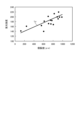
- Fig. 10 is a diagram showing an example of correlation information recorded by the correlation information recording unit 942.
- the vertical axis indicates the emission intensity
- the horizontal axis indicates the invasiveness (depth and area) of the thermal treatment to the biological tissue.
- the line Ly indicates the correlation between the emission intensity and the invasiveness (depth and area) of the thermal treatment to the biological tissue.
- the emission intensity increases as the degree of invasiveness of the thermal treatment to the biological tissue increases.
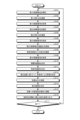
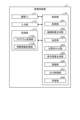
- FIG 11 is a flow chart showing an outline of the process executed by the control device 9.
- control unit 95 controls the light source control unit 34 of the light source device 3 to cause the second light source unit 32 to emit light and supply the first narrowband light to the insertion unit 2, thereby irradiating the first narrowband light toward the biological tissue (step S101).
- control unit 95 controls the imaging control unit 58 to cause the imaging element 53 to capture an image of the first return light from the biological tissue (step S102).
- the acquisition unit 951 acquires a first imaging signal generated by imaging by the imaging element 53 of the endoscopic camera head 5 (step S103).
- control unit 95 controls the light source control unit 34 of the light source device 3 to cause the second light source unit 32 to emit light and supply the second narrowband light to the insertion unit 2, thereby irradiating the second narrowband light toward the biological tissue (step S104).
- the control unit 95 then controls the imaging control unit 58 to cause the imaging element 53 to capture an image of the second return light from the biological tissue (step S105).
- the acquisition unit 951 acquires a second imaging signal generated by imaging by the imaging element 53 of the endoscopic camera head 5 (step S106).
- control unit 95 controls the light source control unit 34 of the light source device 3 to cause the third light source unit 33 to emit light and supply the second narrowband light, which is excitation light, to the insertion unit 2, thereby irradiating the excitation light toward the biological tissue (step S107).
- control unit 95 controls the imaging control unit 58 to cause the imaging element 53 to capture an image of the fluorescence from the thermally denatured region of the biological tissue (step S108).
- the acquisition unit 951 acquires a third imaging signal generated by imaging by the imaging element 53 of the endoscopic camera head 5 (step S109).
- the captured image generating unit 952 generates a hierarchical image that can distinguish the mucosal layer, muscle layer, and fat layer in the generated tissue on a layer-by-layer basis based on the first image signal and the second image signal acquired by the acquiring unit 951 (step S110).
- the control device 9 proceeds to step S111, which will be described later.
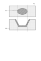
- FIG. 12 is a diagram that illustrates the relationship between the hierarchical images and cross sections of biological tissue.
- the upper row shows the hierarchical image P1
- the lower row shows each layer of the biological tissue.
- the hierarchical image P1 includes an exposed muscle layer region W1 in which the mucosal layer M1 and the muscle layer M2 have been exposed by thermal treatment using an energy device or the like.
- the hierarchical image P1 is in a state in which thermal treatment using an energy device or the like has not yet reached the fat layer M3.
- step S111 the captured image generating section 952 generates a thermal denaturation image based on the third image signal acquired by the acquiring section 951.
- step S112 the control device 9 proceeds to step S112, which will be described later.
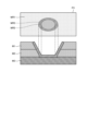
- FIG. 13 is a diagram that illustrates the relationship between a thermal denaturation image and a cross-section of biological tissue.
- the upper part shows a thermal denaturation image P2
- the lower part shows each layer of the biological tissue.
- the thermal denaturation image P2 includes a thermally denatured region W2 that has been caused by thermal treatment using an energy device or the like.
- step S112 the determination unit 953 determines the depth of thermal denaturation based on the correlation information recorded by the correlation information recording unit 942 and the fluorescence intensity from the thermally denatured region included in the thermal denaturation image P2.
- the depth refers to the length from the surface of the biological tissue toward the fat layer.
- the alignment unit 954 performs alignment processing between the hierarchical image P1 and the thermally transformed image P2 (step S113). Specifically, the alignment unit 954 performs alignment processing using well-known techniques so that the positions of the feature amounts contained in the hierarchical image P1 and the feature amounts contained in the thermally transformed image P2 match. For example, the alignment unit 954 performs alignment processing between the hierarchical image P1 and the thermally transformed image P2 based on the positions where the feature amounts of each pixel constituting the hierarchical image P1 and the thermally transformed image P2 match.
- the feature amounts are, for example, pixel values, brightness values, edges, contrast, etc.
- the display image generating unit 955 generates a display image by combining the hierarchical image P1 and the thermally altered image P2 that have been aligned by the alignment unit 954 (step S114).
- the recognition unit 956 recognizes the thermal denaturation of each of the mucosal layer, muscle layer, and fat layer that constitute the biological tissue included in the display image generated by the alignment unit 954 through the alignment process, based on the depth of thermal denaturation determined by the determination unit 953 (step S115). Specifically, the recognition unit 956 recognizes the thermal denaturation of each of the mucosal layer M1, muscle layer M2, and fat layer M3 included in the display image P3, based on the depth of thermal denaturation determined by the determination unit 953. In this case, the recognition unit 956 recognizes the thermal denaturation of each of the mucosal layer M1, muscle layer M2, and fat layer M3 included in the display image P3, based on the depth of thermal denaturation determined by the determination unit 953.
- the output control unit 957 outputs the thermal denaturation to the display device 7 in a different display form for each layer based on the display image generated by the display image generation unit 955 and the recognition result of the thermal denaturation for each layer recognized by the recognition unit 956 (step S116).
- the output control unit 957 outputs the display image P3 to the display device 7 as support information in a different display mode for each layer based on the display image generated by the display image generation unit 955 and the recognition result of the thermal denaturation of each layer recognized by the recognition unit 956. Specifically, the output control unit 957 displays the display areas corresponding to the mucosal layer M1, the muscle layer M2, and the fat layer M3 in "yellow,” "green,” and “blue.” For example, in the case shown in FIG.
- the output control unit 957 displays the thermal denaturation area MR2 of the muscle layer and the thermal denaturation area MR3 of the fat layer in the display image P3 in distinguishable colors, for example, displays the thermal denaturation area of the muscle layer in "green” and displays the thermal denaturation area of the fat layer in "blue,” and outputs the display device 7. This allows the user to intuitively grasp whether or not layers not exposed to the surface have been thermally altered.
- the output control unit 957 distinguishes the display areas corresponding to the mucosal layer M1, the muscle layer M2, and the fat layer M3 by different colors, but this is not limited to this.
- the display areas corresponding to the mucosal layer, the muscle layer, and the fat layer may be output to the display device 7 with the contours of the display areas emphasized for each depth of thermal alteration.
- the output control unit 957 may superimpose the depth of thermal alteration determined by the determination unit 953 on the display image P3 as support information and output it to the display device 7.
- the control unit 95 determines whether or not an end signal to end the observation of the subject by the endoscope system 1 has been input from the input unit 93 (step S117). If the control unit 95 determines that an end signal to end the observation of the subject by the endoscope system 1 has been input from the input unit 93 (step S117: Yes), the control device 9 ends this process. On the other hand, if the control unit 95 determines that an end signal to end the observation of the subject by the endoscope system 1 has not been input from the input unit 93 (step S117: No), the control device 9 returns to step S101 described above.
- the output control unit 957 outputs the display image P3 to the display device 7 as support information, in which the thermal denaturation is displayed in a different manner for each layer, based on the presence or absence of thermal denaturation in each layer of the biological tissue recognized by the recognition unit 956.
- the user can confirm the depth to which the thermal denaturation has penetrated the biological tissue.
- the output control unit 957 may output each layer to the display device 7 in a display mode that differs depending on the depth of thermal denaturation, based on the display image P3 generated by the display image generation unit 955 and the recognition result of the thermal denaturation of each layer recognized by the recognition unit 956.
- the recognition unit 956 recognizes (determines) the thermal denaturation of each of the mucosal layer, muscle layer, and fat layer constituting the biological tissue included in the display image generated by the alignment unit 954 through the alignment process based on the depth of thermal denaturation determined by the determination unit 953, and the output control unit 957 outputs the display image P3 in a display mode to the display device 7 according to the recognition result of the thermal denaturation of each layer recognized by the recognition unit 956. This allows the user to grasp the presence or absence of thermal denaturation of each of the mucosal layer, muscle layer, and fat layer.
- the output control unit 957 may output depth information regarding the depth of thermal denaturation determined by the determination unit 953 as support information.
- the learning unit 958 is provided in the control device 4, but this is not limited thereto, and the learning unit 958 that generates a trained model may be provided in a device different from the control device 4, such as a learning device or a server that can be connected via a network.
- the output control unit 957 may output to the display device 7 a display image generated by the display image generating unit 955 superimposing, in a different display mode for each layer of biological tissue in which thermal denaturation has occurred, on the white light image generated by the captured image generating unit 952. This allows the user to grasp the presence or absence of thermal denaturation in each of the mucosal layer, muscle layer, and fat layer.
- the display image generating unit 955 may generate a display image that emphasizes thermal degeneration in a layer selected by the user according to an instruction signal input from the input unit 93 among the layers of biological tissue in which thermal degeneration has occurred, based on the hierarchical image as the first image and the thermal degeneration image as the second image, and the output control unit 957 may output the display image generated by the display image generating unit 955 to the display device 7. This allows the user to confirm thermal degeneration in the desired layer.
- the control unit 95 of the control device 9 determines the presence or absence of thermal denaturation in a predetermined layer of the biological tissue based on a layer identification image, which is a first image including layer information of a biological tissue having a plurality of layers, and a thermal denaturation image, which is a second image including thermal denaturation information, and outputs support information indicating thermal denaturation in the predetermined layer to the display device 7.
- a medical device that outputs support information is separately provided.
- the configuration of the endoscope system according to the second embodiment will be described below. Note that the same components as those in the endoscope system 1 according to the first embodiment described above are denoted by the same reference numerals, and detailed description thereof will be omitted.
- FIG. 15 is a diagram showing a schematic configuration of an endoscope system according to embodiment 2.
- the endoscope system 1A shown in Fig. 15 includes a control device 9A instead of the control device 9 of the endoscope system 1 according to the above-described embodiment 1.
- the endoscope system 1A further includes a medical device 11 and a fourth transmission cable 12 in addition to the configuration of the endoscope system 1 according to the above-described embodiment 1.
- the control device 9A is realized using a processor, which is a processing device having hardware such as a GPU, FPGA, or CPU, and a memory, which is a temporary storage area used by the processor.
- the control device 9A comprehensively controls the operations of the light source device 3, the endoscopic camera head 5, the display device 7, and the medical device 11 via each of the first transmission cable 6, the second transmission cable 8, the third transmission cable 10, and the fourth transmission cable 12 according to a program recorded in the memory.
- the control device 9A omits the functions of the acquisition unit 951, the captured image generation unit 952, the determination unit 953, the alignment unit 954, the display image generation unit 955, the recognition unit 956, the output control unit 957, and the learning unit 958 from the control unit 95 according to the above-mentioned first embodiment.
- the medical device 11 is realized using a processor, which is a processing device having hardware such as a GPU, FPGA, or CPU, and a memory, which is a temporary storage area used by the processor.
- the medical device 11 acquires various information from the control device 9A via the fourth transmission cable 12, and outputs the acquired various information to the control device 9A.
- the detailed functional configuration of the medical device 11 will be described later.
- the fourth transmission cable 12 has one end detachably connected to the control device 9A and the other end detachably connected to the medical device 11.
- the fourth transmission cable 12 transmits various information from the control device 9A to the medical device 11 and transmits various information from the medical device 11 to the control device 9A.
- Fig. 16 is a block diagram showing the functional configuration of the medical device 11.
- the medical device 11 shown in Fig. 16 includes a communication I/F 111, an input unit 112, a recording unit 113, and a control unit 114.
- the communication I/F 111 is an interface for communicating with the control device 9A via the fourth transmission cable 12.
- the communication I/F 111 receives various information from the control device 9A according to a predetermined communication standard, and outputs the received information to the control unit 114.
- the input unit 112 receives inputs of various operations related to the endoscope system 1A and outputs the received operations to the control unit 114.
- the input unit 112 is configured using a mouse, a foot switch, a keyboard, buttons, switches, a touch panel, etc.
- the recording unit 113 is realized using a recording medium such as a volatile memory, a non-volatile memory, an SSD, an HDD, or a memory card.
- the recording unit 113 records data including various parameters required for the operation of the medical device 11.
- the recording unit 113 also has a program recording unit 113a that records various programs for operating the medical device 11, and a correlation information recording unit 113b that records correlation information indicating the correlation between the invasiveness (depth) of the thermal treatment to the biological tissue and the emission intensity.
- the control unit 114 is realized using a processor having hardware such as an FPGA or a CPU, and a memory that is a temporary storage area used by the processor.
- the control unit 114 comprehensively controls each unit that constitutes the medical device 11.
- the control unit 114 has the same functions as the control unit 95 in the above-mentioned first embodiment. Specifically, the control unit 114 has an acquisition unit 951, a captured image generation unit 952, a determination unit 953, an alignment unit 954, a display image generation unit 955, a recognition unit 956, an output control unit 957, and a learning unit 958.
- the medical device 11 configured in this manner executes the same processing as the control device 9 according to the first embodiment described above, and outputs the processing results to the control device 9A.
- the control device 9A outputs to the display device 7 the display image generated by the image processing unit 92 based on the processing results of the medical device 11, and displays each layer in a different display mode depending on the depth of thermal denaturation based on the recognition results of the thermal denaturation of each layer recognized by the recognition unit 956.
- the second embodiment described above has the same effect as the first embodiment, i.e., the user can check the depth of penetration of the biological tissue by thermal denaturation.
- Various inventions can be formed by appropriately combining multiple components disclosed in the endoscope systems according to the above-mentioned first and second embodiments of the present disclosure. For example, some components may be deleted from all the components described in the endoscope systems according to the above-mentioned embodiments of the present disclosure. Furthermore, the components described in the endoscope systems according to the above-mentioned embodiments of the present disclosure may be appropriately combined.
- the systems are connected to each other by wires, but they may be connected wirelessly via a network.
- the functions of the control unit provided in the endoscope system, and the functional modules of the acquisition unit 951, captured image generation unit 952, decision unit 953, alignment unit 954, display image generation unit 955, recognition unit 956, and output control unit 957 may be provided in a server or the like that can be connected via a network.
- a server may be provided for each functional module.
- transurethral bladder tumor resection an example of use in transurethral bladder tumor resection has been described, but the present disclosure is not limited to this, and can be applied to various procedures, such as resecting lesions using an energy device, etc.
- the "unit” described above can be read as “means” or “circuit.”
- the control unit can be read as control means or control circuit.
Landscapes
- Health & Medical Sciences (AREA)
- Life Sciences & Earth Sciences (AREA)
- Surgery (AREA)
- Engineering & Computer Science (AREA)
- Medical Informatics (AREA)
- Biomedical Technology (AREA)
- Animal Behavior & Ethology (AREA)
- Radiology & Medical Imaging (AREA)
- Optics & Photonics (AREA)
- Nuclear Medicine, Radiotherapy & Molecular Imaging (AREA)
- Physics & Mathematics (AREA)
- Heart & Thoracic Surgery (AREA)
- Biophysics (AREA)
- Molecular Biology (AREA)
- Pathology (AREA)
- General Health & Medical Sciences (AREA)
- Public Health (AREA)
- Veterinary Medicine (AREA)
- Signal Processing (AREA)
- Artificial Intelligence (AREA)
- Evolutionary Computation (AREA)
- Urology & Nephrology (AREA)
- Endoscopes (AREA)
Abstract
Description
本開示は、医療用装置、医療用システム、学習装置、医療用装置の作動方法およびプログラムに関する。 This disclosure relates to a medical device, a medical system, a learning device, and a method and program for operating a medical device.
従来、医療分野では、経尿道的に膀胱腫瘍を切除する手技(経尿道的膀胱腫瘍切除術:TUR-Bt)が広く知られている。この経尿道的膀胱腫瘍切除術(TUR-Bt)では、被検体の尿道から手術用内視鏡(レゼクトスコープ)を挿入し、膀胱の中に灌流液を満たした状態で、術者が手術用内視鏡の接眼部で膀胱壁の腫瘍部を観察しながら、エネルギーデバイス等の切除用処置具を用いて、腫瘍部の表面から削るように腫瘍部を切除する。膀胱壁は、内側から粘膜層、筋層および脂肪層の3層で構成されている。このため、医師や術者等のユーザは、経尿道的膀胱腫瘍切除術において、粘膜層、筋層および脂肪層を識別しながら施術する。 Traditionally, in the medical field, a technique for transurethrally resecting a bladder tumor (transurethral resection of bladder tumor: TUR-Bt) is widely known. In this transurethral resection of bladder tumor (TUR-Bt), a surgical endoscope (resectoscope) is inserted through the urethra of the subject, and the bladder is filled with irrigation fluid. While observing the tumor in the bladder wall through the eyepiece of the surgical endoscope, the surgeon uses a resection treatment tool such as an energy device to resect the tumor by scraping it from the surface of the tumor. From the inside, the bladder wall is composed of three layers: the mucosal layer, the muscle layer, and the fat layer. For this reason, users such as doctors and surgeons perform transurethral resection of bladder tumor while distinguishing between the mucosal layer, the muscle layer, and the fat layer.
例えば、特許文献1では、生体粘膜の吸光度が最大値となる波長を含む第1の波長範囲にピーク波長を有する第1の光と、筋層の吸光度が極大値となる波長を含む第2の波長範囲にピーク波長を有し、かつ、筋層の吸光度に比べて脂肪の吸光度が低い第2の光と、を生体組織に照射し、この生体組織からの戻り光を撮像した第1の画像および第2の画像を用いて、粘膜層、筋層および脂肪層の各々を識別可能な画像を生成する。 For example, in Patent Document 1, a first light having a peak wavelength in a first wavelength range including the wavelength at which the absorbance of the biological mucosa is at its maximum value and a second light having a peak wavelength in a second wavelength range including the wavelength at which the absorbance of the muscle layer is at its maximum value and in which the absorbance of fat is lower than that of the muscle layer are irradiated onto biological tissue, and an image in which each of the mucosal layer, muscle layer, and fat layer can be distinguished is generated using a first image and a second image obtained by capturing the return light from the biological tissue.
しかしながら、上述した特許文献1では、ユーザが切除後に、どの層が露出しているか否かを画像から判別することができるが、切除用処置具を用いた熱変性による生体組織の深達度について何らか考慮されていなかった。このため、ユーザは、熱変性による生体組織の深達度を確認することができる技術が望まれていた。 However, in the above-mentioned Patent Document 1, although the user can determine from the image whether or not a layer is exposed after resection, no consideration is given to the depth of penetration of biological tissue due to thermal denaturation using the resection treatment tool. For this reason, there is a demand for technology that allows users to check the depth of penetration of biological tissue due to thermal denaturation.
本開示は、上記に鑑みてなされたものであって、熱変性による生体組織の深達度を確認することができる、医療用装置、医療用システム、学習装置、医療用装置の作動方法、プログラムを提供することを目的とする。 The present disclosure has been made in consideration of the above, and aims to provide a medical device, a medical system, a learning device, a method for operating a medical device, and a program that can confirm the depth of penetration of biological tissue by thermal denaturation.
上述した課題を解決し、目的を達成するために、本開示に係る医療用装置は、プロセッサを備える医療用装置であって、前記プロセッサは、複数の層で構成される生体組織の層情報を含む第1の画像と、前記生体組織に対する熱処置による熱変性に関する熱変性情報を含む第2の画像と、を取得し、前記第1の画像と、前記第2の画像と、に基づいて、前記生体組織における所定の層への熱変性の有無を判定し、前記熱変性の有無を判定した判定結果に基づいて、前記所定の層への熱変性を示す支援情報を出力する。 In order to solve the above-mentioned problems and achieve the objectives, the medical device disclosed herein is a medical device equipped with a processor, and the processor acquires a first image including layer information of biological tissue composed of multiple layers and a second image including thermal denaturation information related to thermal denaturation caused by thermal treatment of the biological tissue, and determines the presence or absence of thermal denaturation in a specific layer of the biological tissue based on the first image and the second image, and outputs support information indicating thermal denaturation in the specific layer based on the determination result of the presence or absence of the thermal denaturation.
また、本開示に係る医療用装置は、上記開示において、前記層情報は、前記生体組織における脂肪層の情報を含む。 In addition, in the medical device disclosed herein, the layer information includes information about the fat layer in the biological tissue.
また、本開示に係る医療用装置は、上記開示において、前記層情報は、前記生体組織における層の情報を含む。 In addition, in the medical device disclosed herein, the layer information includes information about layers in the biological tissue.
また、本開示に係る医療用装置は、上記開示において、前記第2の画像は、蛍光画像である。 In addition, in the medical device disclosed herein, the second image is a fluorescence image.
また、本開示に係る医療用装置は、上記開示において、前記プロセッサは、予め設定された発光強度と熱変性による表層からの深度との関係を示す相関情報を取得し、前記蛍光画像の発光強度と、前記相関情報と、に基づいて、前記生体組織における表層からの深度を決定し、前記生体組織における表層からの深度に関する深度情報を、支援情報として出力する。 In addition, in the medical device disclosed herein, the processor acquires correlation information indicating the relationship between a preset emission intensity and the depth from the surface due to thermal denaturation, determines the depth from the surface in the biological tissue based on the emission intensity of the fluorescent image and the correlation information, and outputs depth information relating to the depth from the surface in the biological tissue as support information.
また、本開示に係る医療用装置は、上記開示において、前記プロセッサは、前記第1の画像と、前記第2の画像と、に基づいて、前記生体組織における脂肪層への熱変性の有無を判定する。 In addition, in the medical device disclosed herein, the processor determines the presence or absence of thermal denaturation of the fat layer in the biological tissue based on the first image and the second image.
また、本開示に係る医療用装置は、上記開示において、前記プロセッサは、前記第1の画像と、前記第2の画像と、に基づいて、熱変性が生じている前記生体組織の層毎に表示態様を異ならせた表示画像を生成し、前記表示画像を出力する。 In addition, in the medical device disclosed herein, the processor generates a display image in which the display mode differs for each layer of the biological tissue in which thermal denaturation has occurred based on the first image and the second image, and outputs the display image.
また、本開示に係る医療用装置は、上記開示において、前記プロセッサは、白色光が照射された前記生体組織を撮像した白色光画像を取得し、前記熱変性が生じている前記生体組織の層毎に異なる表示態様で前記白色光画像上に重畳することで前記表示画像を生成し、前記表示画像を出力する。 In addition, in the medical device disclosed herein, in the above disclosure, the processor acquires a white light image of the biological tissue irradiated with white light, generates the display image by superimposing on the white light image in a different display mode for each layer of the biological tissue in which thermal denaturation has occurred, and outputs the display image.
また、本開示に係る医療用装置は、上記開示において、前記プロセッサは、前記生体組織における筋層の情報を含む第3の画像を生成する。 In addition, in the medical device disclosed herein, the processor generates a third image including information about the muscle layer in the biological tissue.
また、本開示に係る医療用装置は、上記開示において、前記第3の画像は、前記生体組織における粘膜層の情報を含む。 In addition, in the medical device disclosed herein, the third image includes information about the mucosal layer in the biological tissue.
また、本開示に係る医療用装置は、上記開示において、前記プロセッサは、前記第1の画像と、前記第2の画像と、に基づいて、熱変性が生じている前記生体組織の層のうち、ユーザにより選択された層への熱変性を強調した表示画像を生成し、前記表示画像を出力する。 In addition, in the medical device disclosed herein, the processor generates a display image that emphasizes thermal degeneration in a layer selected by a user from among the layers of the biological tissue in which thermal degeneration is occurring, based on the first image and the second image, and outputs the display image.
また、本開示に係る医療用システムは、光源装置と、撮像装置と、医療用装置と、を備える医療用システムであって、前記光源装置は、複数の層で構成される生体組織の層情報を取得可能な光を発生させる第1の光源と、前記生体組織に熱処置を施すことによって生じる終末糖化産物を励起させる励起光を発生させる第2の光源と、を有し、前記撮像装置は、前記光または前記励起光が照射された前記生体組織からの戻り光または発光を撮像することによって撮像信号を生成する撮像素子を有し、前記医療用装置は、プロセッサを有し、前記プロセッサは、前記撮像素子が前記戻り光を撮像することによって生成した前記撮像信号に基づいて、複数の層で構成される前記生体組織の層情報を含む第1の画像を生成し、前記撮像素子が発光を撮像することによって生成した前記撮像信号に基づいて、前記生体組織に対する熱処置による熱変性に関する熱変性情報を含む第2の画像を生成し、前記第1の画像と、前記第2の画像と、に基づいて、前記生体組織における所定の層への熱変性の有無を判定し、前記熱変性の有無を判定した判定結果に基づいて、前記所定の層への熱変性を示す支援情報を出力する。 The medical system according to the present disclosure is a medical system including a light source device, an imaging device, and a medical device, the light source device having a first light source that generates light capable of acquiring layer information of a biological tissue composed of multiple layers, and a second light source that generates excitation light that excites advanced glycation endproducts generated by applying heat treatment to the biological tissue, the imaging device having an imaging element that generates an imaging signal by imaging return light or light emitted from the biological tissue irradiated with the light or the excitation light, the medical device having a processor, the processor generates a first image including layer information of the biological tissue composed of multiple layers based on the imaging signal generated by the imaging element by imaging the return light, generates a second image including thermal denaturation information regarding thermal denaturation caused by the thermal treatment of the biological tissue based on the imaging signal generated by the imaging element by imaging the light emitted, determines the presence or absence of thermal denaturation in a predetermined layer of the biological tissue based on the first image and the second image, and outputs support information indicating thermal denaturation in the predetermined layer based on the determination result of the presence or absence of thermal denaturation.
また、本開示に係る学習装置は、プロセッサを備える学習装置であって、複数の層で構成される生体組織の層情報を含む第1の画像と、前記生体組織に対する熱処置による熱変性に関する熱変性情報を含む第2の画像と、を入力データとし、前記生体組織における所定の層への熱変性を示す支援情報を出力データとする教師データを用いて機械学習することにより学習済みモデルを生成する。 The learning device according to the present disclosure is a learning device equipped with a processor, which generates a trained model by machine learning using training data in which a first image including layer information of biological tissue composed of multiple layers and a second image including thermal denaturation information related to thermal denaturation caused by heat treatment of the biological tissue are input data, and support information indicating thermal denaturation of a specific layer in the biological tissue is output data.
また、本開示に係る医療用装置の作動方法は、プロセッサを備える医療用装置の作動方法であって、前記プロセッサが、複数の層で構成される生体組織の層情報を含む第1の画像と、前記生体組織に対する熱処置による熱変性に関する熱変性情報を含む第2の画像と、を取得し、前記第1の画像と、前記第2の画像と、に基づいて、前記生体組織における所定の層への熱変性の有無を判定し、前記熱変性の有無を判定した判定結果に基づいて、前記所定の層への熱変性を示す支援情報を出力する。 Furthermore, the method of operating a medical device according to the present disclosure is a method of operating a medical device including a processor, in which the processor acquires a first image including layer information of biological tissue composed of multiple layers and a second image including thermal denaturation information related to thermal denaturation caused by thermal treatment of the biological tissue, determines the presence or absence of thermal denaturation in a specific layer of the biological tissue based on the first image and the second image, and outputs support information indicating thermal denaturation in the specific layer based on the determination result of the presence or absence of the thermal denaturation.
また、本開示に係るプログラムは、プロセッサを備える医療用装置が実行するプログラムであって、前記プロセッサに、複数の層で構成される生体組織の層情報を含む第1の画像と、前記生体組織に対する熱処置による熱変性に関する熱変性情報を含む第2の画像と、を取得し、前記第1の画像と、前記第2の画像と、に基づいて、前記生体組織における所定の層への熱変性の有無を判定し、前記熱変性の有無を判定した判定結果に基づいて、前記所定の層への熱変性を示す支援情報を出力する、ことを実行させる。 The program according to the present disclosure is a program executed by a medical device having a processor, and causes the processor to acquire a first image including layer information of biological tissue composed of multiple layers and a second image including thermal denaturation information related to thermal denaturation caused by thermal treatment of the biological tissue, determine the presence or absence of thermal denaturation in a specific layer of the biological tissue based on the first image and the second image, and output support information indicating thermal denaturation in the specific layer based on the determination result of the presence or absence of the thermal denaturation.
本開示によれば、熱変性による生体組織の深達度を確認することができるという効果を奏する。 The present disclosure has the effect of making it possible to confirm the depth to which thermal denaturation has penetrated biological tissue.
以下、本開示を実施するための形態を図面とともに詳細に説明する。なお、以下の実施の形態により本開示が限定されるものでない。また、以下の説明において参照する各図は、本開示の内容を理解でき得る程度に形状、大きさ、および位置関係を概略的に示してあるに過ぎない。即ち、本開示は、各図で例示された形状、大きさ、および位置関係のみに限定されるものでない。さらに、図面の記載において、同一の部分には同一の符号を付して説明する。さらにまた、本開示に係る医療用システムの一例として、硬性鏡および医療用撮像装置を備える内視鏡システムについて説明する。 Below, the embodiments for implementing this disclosure will be described in detail with reference to the drawings. Note that this disclosure is not limited to the following embodiments. Furthermore, each figure referred to in the following description merely shows a schematic representation of the shape, size, and positional relationship to the extent that the contents of this disclosure can be understood. In other words, this disclosure is not limited to only the shape, size, and positional relationship exemplified in each figure. Furthermore, in the description of the drawings, identical parts are denoted by the same reference numerals. Furthermore, an endoscopic system equipped with a rigid endoscope and a medical imaging device will be described as an example of a medical system according to this disclosure.
(実施の形態1)
〔内視鏡システムの構成〕
図1は、実施の形態1に係る内視鏡システムの概略構成を示す図である。図1に示す内視鏡システム1は、医療分野に用いられ、生体等の被検体内の生体組織を観察および処置するシステムである。なお、実施の形態1では、内視鏡システム1として、図1に示す硬性鏡(挿入部2)を用いた硬性内視鏡システムについて説明するが、これに限定されることなく、例えば軟性の内視鏡を備えた内視鏡システムであってもよい。さらに、内視鏡システム1として、被検体を撮像する医療用撮像装置を備え、この医療用撮像装置によって撮像された撮像信号(画像データ)に基づく観察画像を表示装置に表示させながら手術や処理等を行う医療用顕微鏡または医療用手術ロボットシステム等のものであっても適用することができる。また、図1に示す内視鏡システム1は、熱処置が可能なエネルギーデバイス等の処置具(図示せず)を用いて被検体の手術または処理を行う際に用いられる。具体的には、図1に示す内視鏡システム1は、経尿道的膀胱腫瘍切除術(TUR-Bt)に用いられ、膀胱の腫瘍(膀胱がん)や病変領域に対して処置を行う際に用いられる。
(Embodiment 1)
[Configuration of the endoscope system]
FIG. 1 is a diagram showing a schematic configuration of an endoscope system according to a first embodiment. The endoscope system 1 shown in FIG. 1 is used in the medical field, and is a system for observing and treating biological tissue in a subject such as a living body. In the first embodiment, a rigid endoscope system using a rigid endoscope (insertion unit 2) shown in FIG. 1 will be described as the endoscope system 1, but the present invention is not limited to this, and may be, for example, an endoscope system equipped with a flexible endoscope. Furthermore, the endoscope system 1 may be applied to a medical microscope or a medical surgery robot system that includes a medical imaging device for imaging a subject and performs surgery or treatment while displaying an observation image based on an imaging signal (image data) captured by the medical imaging device on a display device. The endoscope system 1 shown in FIG. 1 is used when performing surgery or treatment on a subject using a treatment tool (not shown) such as an energy device capable of thermal treatment. Specifically, the endoscope system 1 shown in FIG. 1 is used in transurethral resection of bladder tumor (TUR-Bt) and is used when performing treatment on a tumor (bladder cancer) or a lesion area of the bladder.
図1に示す内視鏡システム1は、挿入部2と、光源装置3と、ライトガイド4と、内視鏡カメラヘッド5(内視鏡用撮像装置)と、第1の伝送ケーブル6と、表示装置7と、第2の伝送ケーブル8と、制御装置9と、第3の伝送ケーブル10と、を備える。 The endoscope system 1 shown in FIG. 1 includes an insertion section 2, a light source device 3, a light guide 4, an endoscope camera head 5 (an endoscopic imaging device), a first transmission cable 6, a display device 7, a second transmission cable 8, a control device 9, and a third transmission cable 10.
挿入部2は、硬質または少なくとも一部が軟性で細長形状を有する。挿入部2は、トロッカーを経由して患者等の被検体内に挿入される。挿入部2は、内部に観察像を結像するレンズ等の光学系が設けられている。 The insertion section 2 is hard or at least partially soft and has an elongated shape. The insertion section 2 is inserted into a subject such as a patient via a trocar. The insertion section 2 is provided with an optical system such as a lens that forms an observation image inside.
光源装置3は、ライトガイド4の一端が接続され、制御装置9による制御のもと、ライトガイド4の一端に被検体内に照射する照明光を供給する。光源装置3は、LED(Light Emitting Diode)光源、キセノンランプおよびLD(laser Diode)等の半導体レーザ素子のいずれかの1つ以上の光源と、FPGA(Field Programmable Gate Array)やCPU(Central Processing Unit)等のハードウェアを有する処理装置であるプロセッサと、プロセッサが使用する一時的な記憶域であるメモリを用いて実現される。なお、光源装置3および制御装置9は、図1に示すように個別に通信する構成をしてもよいし、一体化した構成であってもよい。 The light source device 3 is connected to one end of the light guide 4, and under the control of the control device 9, supplies illumination light to one end of the light guide 4 to be irradiated into the subject. The light source device 3 is realized using one or more light sources, such as an LED (Light Emitting Diode) light source, a xenon lamp, or a semiconductor laser element such as an LD (laser diode), a processor which is a processing device having hardware such as an FPGA (Field Programmable Gate Array) or a CPU (Central Processing Unit), and a memory which is a temporary storage area used by the processor. The light source device 3 and the control device 9 may be configured to communicate individually as shown in FIG. 1, or may be integrated.
ライトガイド4は、一端が光源装置3に着脱自在に接続され、かつ、他端が挿入部2に着脱自在に接続される。ライトガイド4は、光源装置3から供給された照明光を一端から端に導光し、挿入部2へ供給する。 One end of the light guide 4 is detachably connected to the light source device 3, and the other end is detachably connected to the insertion section 2. The light guide 4 guides the illumination light supplied from the light source device 3 from one end to the other, and supplies it to the insertion section 2.
内視鏡カメラヘッド5は、挿入部2の接眼部21が着脱自在に接続される。内視鏡カメラヘッド5は、制御装置9による制御のもと、挿入部2によって結像された観察像を受光して光電変換を行うことによって撮像信号(RAWデータ)を生成し、この撮像信号を第1の伝送ケーブル6を経由して制御装置9へ出力する。 The endoscopic camera head 5 is detachably connected to the eyepiece 21 of the insertion section 2. Under the control of the control device 9, the endoscopic camera head 5 receives the observation image formed by the insertion section 2 and performs photoelectric conversion to generate an imaging signal (RAW data), and outputs this imaging signal to the control device 9 via the first transmission cable 6.
第1の伝送ケーブル6は、一端がビデオコネクタ61を経由して制御装置9に着脱自在に接続され、他端がカメラヘッドコネクタ62を経由して内視鏡カメラヘッド5に着脱自在に接続される。第1の伝送ケーブル6は、内視鏡カメラヘッド5から出力される撮像信号を制御装置9へ伝送し、かつ、制御装置9から出力される設定データおよび電力等を内視鏡カメラヘッド5へ伝送する。ここで、設定データとは、内視鏡カメラヘッド5を制御する制御信号、同期信号およびクロック信号等である。 One end of the first transmission cable 6 is detachably connected to the control device 9 via a video connector 61, and the other end is detachably connected to the endoscopic camera head 5 via a camera head connector 62. The first transmission cable 6 transmits the imaging signal output from the endoscopic camera head 5 to the control device 9, and also transmits setting data, power, etc. output from the control device 9 to the endoscopic camera head 5. Here, the setting data refers to a control signal, synchronization signal, clock signal, etc. that controls the endoscopic camera head 5.
表示装置7は、制御装置9による制御のもと、制御装置9において画像処理が施された撮像信号に基づく観察画像および内視鏡システム1に関する各種情報を表示する。表示装置7は、液晶または有機EL(Electro Luminescence)等の表示モニタを用いて実現される。 Under the control of the control device 9, the display device 7 displays an observation image based on an imaging signal that has been subjected to image processing in the control device 9, and various information related to the endoscope system 1. The display device 7 is realized using a display monitor such as a liquid crystal or organic EL (Electro Luminescence) display.
第2の伝送ケーブル8は、一端が表示装置7に着脱自在に接続され、他端が制御装置9に着脱自在に接続される。第2の伝送ケーブル8は、制御装置9において画像処理が施された撮像信号を表示装置7へ伝送する。 One end of the second transmission cable 8 is detachably connected to the display device 7, and the other end is detachably connected to the control device 9. The second transmission cable 8 transmits the image signal that has been subjected to image processing in the control device 9 to the display device 7.
制御装置9は、GPU(Graphics Processing Unit)、FPGAまたはCPU等のハードウェアを有する処理装置であるプロセッサと、プロセッサが使用する一時的な記憶域であるメモリと、を用いて実現される。制御装置9は、メモリに記録されたプログラムに従って、第1の伝送ケーブル6、第2の伝送ケーブル8および第3の伝送ケーブル10の各々を経由して、光源装置3、内視鏡カメラヘッド5および表示装置7の動作を統括的に制御する。また、制御装置9は、第1の伝送ケーブル6を経由して入力された撮像信号に対して各種の画像処理を行って第2の伝送ケーブル8へ出力する。なお、実施の形態1では、制御装置9が医療用装置として機能する。 The control device 9 is realized using a processor, which is a processing device having hardware such as a GPU (Graphics Processing Unit), FPGA, or CPU, and a memory, which is a temporary storage area used by the processor. The control device 9 comprehensively controls the operation of the light source device 3, the endoscopic camera head 5, and the display device 7 via each of the first transmission cable 6, the second transmission cable 8, and the third transmission cable 10 according to a program recorded in the memory. The control device 9 also performs various image processing on the imaging signal input via the first transmission cable 6 and outputs it to the second transmission cable 8. In the first embodiment, the control device 9 functions as a medical device.
第3の伝送ケーブル10は、一端が光源装置3に着脱自在に接続され、他端が制御装置9に着脱自在に接続される。第3の伝送ケーブル10は、制御装置9からの制御データを光源装置3へ伝送する。 The third transmission cable 10 has one end detachably connected to the light source device 3 and the other end detachably connected to the control device 9. The third transmission cable 10 transmits control data from the control device 9 to the light source device 3.
〔内視鏡システムの要部の機能構成〕
次に、上述した内視鏡システム1の要部の機能構成について説明する。図2は、内視鏡システム1の要部の機能構成を示すブロック図である。
[Functional configuration of main parts of endoscope system]
Next, a description will be given of the functional configuration of the main parts of the above-mentioned endoscope system 1. Fig. 2 is a block diagram showing the functional configuration of the main parts of the endoscope system 1.
〔挿入部の構成〕
まず、挿入部2の構成について説明する。挿入部2は、光学系22と、照明光学系23と、を有する。
[Configuration of Insertion Part]
First, a description will be given of the configuration of the insertion portion 2. The insertion portion 2 has an optical system 22 and an illumination optical system 23.
光学系22は、被写体から反射された反射光、被写体からの戻り光、被写体からの励起光およびエネルギーデバイス等の熱処置によって熱変成した熱変性領域から発せられた蛍光等の光を集光することによって被写体像を結像する。光学系22は、1または複数のレンズ等を用いて実現される。 The optical system 22 forms an image of the subject by collecting light such as reflected light from the subject, return light from the subject, excitation light from the subject, and fluorescence emitted from a thermally denatured region that has been thermally denatured by a thermal treatment such as an energy device. The optical system 22 is realized using one or more lenses, etc.
照明光学系23は、ライトガイド4から供給されて照明光を被写体に向けて照射する。照明光学系23は、1または複数のレンズ等を用いて実現される。 The illumination optical system 23 irradiates the subject with illumination light supplied from the light guide 4. The illumination optical system 23 is realized using one or more lenses, etc.
〔光源装置の構成〕
次に、光源装置3の構成について説明する。光源装置3は、集光レンズ30と、第1の光源部31と、第2の光源部32と、第3の光源部33と、光源制御部34と、を備える。
[Configuration of the Light Source Device]
Next, a description will be given of the configuration of the light source device 3. The light source device 3 includes a condenser lens 30, a first light source unit 31, a second light source unit 32, a third light source unit 33, and a light source control unit .
集光レンズ30は、第1の光源部31、第2の光源部32および第3の光源部33の各々が発光した光を集光してライトガイド4へ出射する。 The focusing lens 30 focuses the light emitted by each of the first light source unit 31, the second light source unit 32, and the third light source unit 33, and emits the light to the light guide 4.
第1の光源部31は、光源制御部34による制御のもと、可視光である白色光(通常光)を発光することによってライトガイド4へ照明光として白色光を供給する。第1の光源部31は、コリメートレンズ、白色LEDランプおよび駆動ドライバ等を用いて構成される。なお、第1の光源部31は、赤色LEDランプ、緑色LEDランプおよび青色LEDランプを用いて同時に発光することによって可視光の白色光を供給してもよい。もちろん、第1の光源部31は、ハロゲンランプやキセノンランプ等を用いて構成されてもよい。 The first light source unit 31 emits visible white light (normal light) under the control of the light source control unit 34, thereby supplying white light as illumination light to the light guide 4. The first light source unit 31 is configured using a collimator lens, a white LED lamp, a driving driver, etc. The first light source unit 31 may supply visible white light by simultaneously emitting light using a red LED lamp, a green LED lamp, and a blue LED lamp. Of course, the first light source unit 31 may also be configured using a halogen lamp, a xenon lamp, etc.
第2の光源部32は、光源制御部34による制御のもと、所定の波長帯域を有する第1の狭帯域光を発光することによってライトガイド4へ照明光として第1の狭帯域光を供給する。ここで、第1の狭帯域光は、波長帯域が530nm~550nm(中心波長が540nm)である。第2の光源部32は、緑色LEDランプ、コリメートレンズ、530nm~550nmの光を透過させる透過フィルタおよび駆動ドライバ等を用いて構成される。 The second light source unit 32 emits first narrowband light having a predetermined wavelength band under the control of the light source control unit 34, thereby supplying the first narrowband light as illumination light to the light guide 4. Here, the first narrowband light has a wavelength band of 530 nm to 550 nm (with a central wavelength of 540 nm). The second light source unit 32 is configured using a green LED lamp, a collimating lens, a transmission filter that transmits light of 530 nm to 550 nm, a driver, etc.
第3の光源部33は、光源制御部34による制御のもと、第1の狭帯域光と異なる波長帯域の第2の狭帯域光を発光することによってライトガイド4へ照明光として第2の狭帯域光を供給する。ここで、第2の狭帯域光は、波長帯域が400nm~430nm(中心波長が415nm)である。第3の光源部33は、コリメートレンズ、紫色LD(laser Diode)等の半導体レーザおよび駆動ドライバ等を用いて実現される。なお、実施の形態1では、第2の狭帯域光が生体組織に熱処置を施すことによって生じる終末糖化産物を励起させる励起光として機能する。 The third light source unit 33, under the control of the light source control unit 34, emits second narrowband light of a wavelength band different from the first narrowband light, thereby supplying the second narrowband light as illumination light to the light guide 4. Here, the second narrowband light has a wavelength band of 400 nm to 430 nm (center wavelength 415 nm). The third light source unit 33 is realized using a collimating lens, a semiconductor laser such as a violet LD (laser diode), a driving driver, etc. In addition, in the first embodiment, the second narrowband light functions as excitation light that excites advanced glycation endproducts generated by applying heat treatment to biological tissue.
光源制御部34は、FPGAまたはCPU等のハードウェアを有する処理装置であるプロセッサと、プロセッサが使用する一時的な記憶域であるメモリを用いて実現される。光源制御部34は、制御装置9から入力される制御データに基づいて、第1の光源部31、第2の光源部32および第3の光源部33の各々の発光タイミングおよび発光時間等を制御する。 The light source control unit 34 is realized using a processor, which is a processing device having hardware such as an FPGA or a CPU, and a memory, which is a temporary storage area used by the processor. The light source control unit 34 controls the light emission timing and light emission time of each of the first light source unit 31, the second light source unit 32, and the third light source unit 33 based on control data input from the control device 9.
ここで、第2の光源部32および第3の光源部33の各々が発光する光の波長特性について説明する。図3は、第2の光源部32および第3の光源部33の各々が発光する光の波長特性を模式的に示す図である。図3において、横軸が波長(nm)を示し、縦軸が波長特性を示す。また、図3において、折れ線LNGが第2の光源部32が発光する第1の狭帯域光の波長特性を示し、折れ線LVが第3の光源部33が発光する第2の狭帯域光(励起光)の波長特性を示す。また、図3において、曲線LBが青色の波長帯域を示し、曲線LGが緑色の波長帯域を示し、曲線LRが赤色の波長帯域を示す。 Here, the wavelength characteristics of the light emitted by each of the second light source unit 32 and the third light source unit 33 will be described. Fig. 3 is a diagram showing a schematic diagram of the wavelength characteristics of the light emitted by each of the second light source unit 32 and the third light source unit 33. In Fig. 3, the horizontal axis indicates the wavelength (nm), and the vertical axis indicates the wavelength characteristics. In Fig. 3, the broken line L NG indicates the wavelength characteristics of the first narrowband light emitted by the second light source unit 32, and the broken line L V indicates the wavelength characteristics of the second narrowband light (excitation light) emitted by the third light source unit 33. In Fig. 3, the curve L B indicates the blue wavelength band, the curve L G indicates the green wavelength band, and the curve L R indicates the red wavelength band.
図3の折れ線LNGに示すように、第2の光源部32は、中心波長(ピーク波長)が540nmであり、波長帯域530nm~550nmである狭帯域光を発光する。また、第3の光源部33は、中心波長(ピーク波長)が415nmであり、波長帯域が400nm~430nmである励起光を発光する。 3 , the second light source unit 32 emits narrowband light having a center wavelength (peak wavelength) of 540 nm and a wavelength band of 530 nm to 550 nm, and the third light source unit 33 emits excitation light having a center wavelength (peak wavelength) of 415 nm and a wavelength band of 400 nm to 430 nm.
このように、第2の光源部32および第3の光源部33の各々は、互いに異なる波長帯域の第1の狭帯域光および第2の狭帯域光(励起光)を発光する。 In this way, the second light source unit 32 and the third light source unit 33 each emit a first narrowband light and a second narrowband light (excitation light) of mutually different wavelength bands.
また、第1の狭帯域光は、生体組織における層判別用の光となす。具体的には、第1の狭帯域光は、被写体である粘膜層の吸光度と被写体である筋層の吸光度との差が、2つの被写体を識別可能な程度に大きくなる。このため、層判別用の第1の狭帯域光の照射により取得される層判別用の第2の画像のうち、粘膜層を撮像した領域は、筋層を撮像した領域に比べて画素値(輝度値)が小さく、暗くなる。即ち、実施の形態1では、層判別用の第2の画像を表示画像の生成に用いることによって、粘膜層と筋層とを識別が容易な表示態様とすることが可能になる。 The first narrowband light is used for layer discrimination in biological tissue. Specifically, the first narrowband light increases the difference between the absorbance of the mucosal layer, which is the subject, and the absorbance of the muscle layer, which is the subject, to a degree that makes it possible to distinguish the two subjects. For this reason, in the second image for layer discrimination acquired by irradiating the first narrowband light for layer discrimination, the area in which the mucosal layer is imaged has a smaller pixel value (brightness value) and is darker than the area in which the muscle layer is imaged. That is, in the first embodiment, by using the second image for layer discrimination to generate a display image, it is possible to achieve a display mode in which the mucosal layer and the muscle layer can be easily distinguished.
また、第2の狭帯域光(励起光)は、第1の狭帯域光と異なる生体組織における層判別用の光となす。具体的には、第2の狭帯域光は、被写体である筋層の吸光度と被写体である脂肪層の吸光度の差が、2つの被写体を識別可能な程度に大きくなる。このため、層判別用の第2の狭帯域光の照射により取得される層判別用の第2の光画像のうち、筋層を撮像した領域は、脂肪層を撮像した領域に比べて画素値(輝度値)が小さく、暗くなる。即ち、層判別用の第2の画像を表示画像の生成に用いることによって、筋層と脂肪層とを識別が容易な態様とすることが可能になる。 The second narrowband light (excitation light) is light for layer discrimination in biological tissue that is different from the first narrowband light. Specifically, the second narrowband light increases the difference in absorbance between the muscle layer, which is the subject, and the fat layer, which is the subject, to a degree that makes it possible to distinguish between the two subjects. Therefore, in the second light image for layer discrimination obtained by irradiating the second narrowband light for layer discrimination, the area in which the muscle layer is imaged has a smaller pixel value (brightness value) and is darker than the area in which the fat layer is imaged. In other words, by using the second image for layer discrimination to generate a display image, it becomes possible to easily distinguish between the muscle layer and the fat layer.
粘膜層(生体粘膜)および筋層は、いずれもミオグロビンを多く含む被写体である。ただし、含まれるミオグロビンの濃度は、粘膜層が相対的に高く、筋層が相対的に低い。粘膜層と筋層との吸光特性に差異が生じる原因は、粘膜層(生体粘膜)および筋層の各々に含まれるミオグロビン濃度の差に起因する。そして、粘膜層と筋層との吸光度の差は、生体粘膜の吸光度が最大値となる波長の近傍において最大となる。即ち、層判別用の第1の狭帯域光とは、他の波長帯域にピーク波長を有する光に比べて、粘膜層と筋層との差が大きく現れる光となる。 Both the mucosal layer (biological mucosa) and the muscular layer are subjects that contain a large amount of myoglobin. However, the concentration of myoglobin contained is relatively high in the mucosal layer and relatively low in the muscular layer. The difference in the absorption characteristics between the mucosal layer and the muscular layer is caused by the difference in the concentration of myoglobin contained in each of the mucosal layer (biological mucosa) and the muscular layer. The difference in absorbance between the mucosal layer and the muscular layer is greatest near the wavelength at which the absorbance of the biological mucosa is at its maximum. In other words, the first narrowband light for layer discrimination is light that shows a greater difference between the mucosal layer and the muscular layer than light that has a peak wavelength in another wavelength band.
また、層判別用の第2の狭帯域光は、筋層の吸光度に比べて脂肪の吸光度が低いため、層判別用の第2の狭帯域光の照射によって撮像される第2の画像において、筋層が撮像される領域の画素値(輝度値)が、脂肪層が撮像される領域の画素値(輝度値)に比べて小さくなる。特に、層判別用の第2の狭帯域光は、筋層の吸光度が極大値となる波長に対応する光であるため、筋層と脂肪層との差が大きく現れる光となる。即ち、層判別用の第2の画像における筋層領域の画素値(輝度値)と、脂肪層領域の画素値(輝度値)との差が、識別可能な程度に大きくなる。 In addition, because the second narrowband light for layer discrimination has a lower absorbance of fat compared to the absorbance of the muscle layer, in the second image captured by irradiating the second narrowband light for layer discrimination, the pixel value (brightness value) of the area in which the muscle layer is imaged is smaller than the pixel value (brightness value) of the area in which the fat layer is imaged. In particular, the second narrowband light for layer discrimination is light that corresponds to a wavelength at which the absorbance of the muscle layer is at its maximum, and therefore becomes light that greatly reveals the difference between the muscle layer and the fat layer. In other words, the difference between the pixel value (brightness value) of the muscle layer area and the pixel value (brightness value) of the fat layer area in the second image for layer discrimination becomes large enough to be distinguished.
このように光源装置3は、第1の狭帯域光および第2の狭帯域光の各々を生体組織に照射する。これにより、後述する内視鏡カメラヘッド5は、生体組織からの戻り光を撮像することによって生体組織を構成する粘膜層、筋層および脂肪層の各々を識別可能な画像を得ることができる。 In this way, the light source device 3 irradiates the biological tissue with each of the first narrowband light and the second narrowband light. This allows the endoscopic camera head 5, which will be described later, to obtain an image in which the mucosal layer, muscle layer, and fat layer that make up the biological tissue can be identified by capturing the light returned from the biological tissue.
また、実施の形態1では、第2の狭帯域光(励起光)がエネルギーデバイス等によって生体組織に熱処置が施されることによって生じる終末糖化産物を励起させる。ところで、アミノ酸と、還元糖と、を加熱した場合、糖化反応(メイラード反応)が生じる。このメイラード反応の結果生じる最終産物は、総じて終末糖化産物(AGEs:Advanced glycation end products)と呼ばれる。AGEsの特徴としては、蛍光特性を有する物質が含まれることが知られている。つまり、AGEsは、生体組織をエネルギーデバイスで熱処置した場合、生体組織中のアミノ酸と還元糖が加熱されて、メイラード反応が生じることによって生成される。この加熱により生成されたAGEsは、蛍光観察することにより熱処置の状態の可視化が可能となる。さらに、AGEsは、生体組織内に元来存在する自家蛍光物質よりも、強い蛍光を発するが知られている。即ち、実施の形態1では、エネルギーデバイス等により熱処置されることで生体組織中に発生したAGEsの蛍光特性を利用して、熱処置による熱変性領域を可視化する。このため、実施の形態1では、第2の光源部32(励起光)からAGEsを励起させるための波長415nmm近傍の青色光の励起光を生体組織に照射する。これにより、実施の形態1は、AGEsから発生する熱変性領域から発せられる蛍光(例えば、波長490~625nmの緑色光)を撮像した撮像信号に基づいて、蛍光画像(熱変性画像)を観察することができる。 In addition, in the first embodiment, the second narrowband light (excitation light) excites advanced glycation end products that are generated by subjecting biological tissue to heat treatment by an energy device or the like. When amino acids and reducing sugars are heated, a glycation reaction (Maillard reaction) occurs. The end products resulting from this Maillard reaction are generally called advanced glycation end products (AGEs). It is known that AGEs are characterized by the inclusion of substances with fluorescent properties. In other words, when biological tissue is heat-treated with an energy device, AGEs are generated by heating amino acids and reducing sugars in the biological tissue and causing a Maillard reaction. The AGEs generated by this heating can be visualized in the state of the heat treatment by fluorescent observation. Furthermore, it is known that AGEs emit stronger fluorescence than the autofluorescent substances that are originally present in biological tissue. In other words, in the first embodiment, the fluorescent properties of AGEs generated in biological tissue by heat treatment by an energy device or the like are utilized to visualize the thermally denatured area caused by the heat treatment. For this reason, in the first embodiment, the second light source unit 32 (excitation light) irradiates the biological tissue with blue excitation light with a wavelength of about 415 nm in order to excite AGEs. As a result, in the first embodiment, a fluorescent image (thermal denaturation image) can be observed based on an imaging signal that captures the fluorescence (e.g., green light with a wavelength of 490 to 625 nm) emitted from the thermal denaturation region generated by the AGEs.
〔内視鏡カメラヘッドの構成〕
図2に戻り、内視鏡システム1の構成の説明を続ける。
次に、内視鏡カメラヘッド5の構成について説明する。内視鏡カメラヘッド5は、光学系51と、駆動部52と、撮像素子53と、カットフィルタ54と、A/D変換部55と、P/S変換部56と、撮像記録部57と、撮像制御部58と、を備える。
[Configuration of the endoscope camera head]
Returning to FIG. 2, the description of the configuration of the endoscope system 1 will continue.
Next, a description will be given of the configuration of the endoscopic camera head 5. The endoscopic camera head 5 includes an optical system 51, a drive unit 52, an image sensor 53, a cut filter 54, an A/D conversion unit 55, a P/S conversion unit 56, an image capture recording unit 57, and an image capture control unit 58.
光学系51は、挿入部2の光学系22が集光した被写体像を撮像素子53の受光面に結像する。光学系51は、焦点距離および焦点位置を変更可能である。光学系51は、複数のレンズ511を用いて構成される。光学系51は、駆動部52によって複数のレンズ511の各々が光軸L1上を移動することによって、焦点距離および焦点位置を変更する。 The optical system 51 forms an image of the subject collected by the optical system 22 of the insertion part 2 on the light receiving surface of the image sensor 53. The optical system 51 is capable of changing the focal length and focal position. The optical system 51 is configured using a plurality of lenses 511. The optical system 51 changes the focal length and focal position by moving each of the plurality of lenses 511 on the optical axis L1 using the drive part 52.
駆動部52は、撮像制御部58による制御のもと、光学系51の複数のレンズ511を光軸L1上に沿って移動させる。駆動部52は、ステッピングモータ、DCモータおよびボイスコイルモータ等のモータと、光学系51にモータの回転を伝達するギア等の伝達機構と、を用いて構成される。 The driving unit 52 moves the multiple lenses 511 of the optical system 51 along the optical axis L1 under the control of the imaging control unit 58. The driving unit 52 is configured using a motor such as a stepping motor, a DC motor, or a voice coil motor, and a transmission mechanism such as a gear that transmits the rotation of the motor to the optical system 51.
撮像素子53は、2次元マトリクス状に配置されてなる複数の画素を有するCCD(Charge Coupled Device)またはCMOS(Complementary Metal Oxide Semiconductor)のイメージセンサを用いて実現される。撮像素子53は、撮像制御部58による制御のもと、光学系51によって結像された被写体像(光線)であって、カットフィルタ54を経由した被写体像を受光し、光電変換を行って撮像信号(RAWデータ)を生成してA/D変換部55へ出力する。撮像素子53は、画素部531と、カラーフィルタ532と、を有する。 The imaging element 53 is realized by using a CCD (Charge Coupled Device) or CMOS (Complementary Metal Oxide Semiconductor) image sensor having multiple pixels arranged in a two-dimensional matrix. Under the control of the imaging control unit 58, the imaging element 53 receives the subject image (light rays) formed by the optical system 51 through the cut filter 54, performs photoelectric conversion to generate an imaging signal (RAW data), and outputs it to the A/D conversion unit 55. The imaging element 53 has a pixel unit 531 and a color filter 532.
図4は、画素部531の構成を模式的に示す図である。図4に示すように、画素部531は、光量に応じた電荷を蓄積するフォトダイオード等の複数の画素Pnm(n=1以上の整数,m=1以上の整数)が2次元マトリクス状に配置されてなる。画素部531は、撮像制御部58による制御のもと、複数の画素Pnmのうち読み出し対象として任意に設定された読み出し領域の画素Pnmから画像信号を画像データとして読み出してA/D変換部55へ出力する。 Fig. 4 is a diagram showing a schematic configuration of the pixel unit 531. As shown in Fig. 4, the pixel unit 531 is configured by arranging a plurality of pixels Pnm (n = an integer of 1 or more, m = an integer of 1 or more) such as photodiodes that accumulate electric charges according to the amount of light in a two-dimensional matrix. Under the control of the imaging control unit 58, the pixel unit 531 reads out image signals as image data from pixels Pnm in a readout region arbitrarily set as a readout target among the plurality of pixels Pnm , and outputs the image signals to the A/D conversion unit 55.
図5は、カラーフィルタ532の構成を模式的に示す図である。図5に示すように、カラーフィルタ532は、2×2を1つのユニットとするベイヤー配列で構成される。カラーフィルタ532は、赤色の波長帯域の光を透過するフィルタRと、緑色の波長帯域の光を透過する2つのフィルタGと、青色の波長帯域の光を透過するフィルタBと、を用いて構成される。 FIG. 5 is a diagram showing a schematic configuration of color filter 532. As shown in FIG. 5, color filter 532 is configured in a Bayer array with 2×2 as one unit. Color filter 532 is configured using a filter R that transmits light in the red wavelength band, two filters G that transmit light in the green wavelength band, and a filter B that transmits light in the blue wavelength band.
図6は、各フィルタの感度と波長帯域を模式的に示す図である。図6において、横軸が波長(nm)を示し、縦軸が透過特性(感度特性)を示す。また、図6において、曲線LBがフィルタBの透過特性を示し、曲線LGがフィルタGの透過特性を示し、曲線LRがフィルタRの透過特性を示す。 Fig. 6 is a diagram showing the sensitivity and wavelength band of each filter. In Fig. 6, the horizontal axis indicates wavelength (nm) and the vertical axis indicates transmission characteristics (sensitivity characteristics). In Fig. 6, the curve L- B indicates the transmission characteristics of filter B, the curve L- G indicates the transmission characteristics of filter G, and the curve L- R indicates the transmission characteristics of filter R.
図6の曲線LBに示すように、フィルタBは、青色の波長帯域の光を透過する。また、図6の曲線LGが示すように、フィルタGは、緑色の波長帯域の光を透過する。さらに、図6の曲線LRが示すように、フィルタRは、赤色の波長帯域の光を透過する。なお、以下においては、フィルタRが受光面に配置されてなる画素PnmをR画素、フィルタGが受光面に配置されてなる画素PnmをG画素、フィルタBが受光面に配置されてなる画素PnmをB画素として表記して説明する。 As shown by the curve L- B in Fig. 6, the filter B transmits light in the blue wavelength band. Moreover, as shown by the curve L -G in Fig. 6, the filter G transmits light in the green wavelength band. Moreover, as shown by the curve L -R in Fig. 6, the filter R transmits light in the red wavelength band. In the following description, the pixel P- nm having the filter R disposed on the light receiving surface is referred to as the R pixel, the pixel P -nm having the filter G disposed on the light receiving surface is referred to as the G pixel, and the pixel P -nm having the filter B disposed on the light receiving surface is referred to as the B pixel.
このように構成された撮像素子53によれば、光学系51によって結像された被写体像を受光した場合、図7A~図7Cに示すように、R画素、G画素およびB画素の各々の色信号(R信号、G信号およびB信号)を生成する。 When the image sensor 53 configured in this manner receives the subject image formed by the optical system 51, it generates color signals (R signal, G signal, and B signal) for the R pixel, G pixel, and B pixel, respectively, as shown in Figures 7A to 7C.
図2に戻り、内視鏡システム1の構成の説明を続ける。
カットフィルタ54は、光学系51と撮像素子53との光軸L1上に配置される。カットフィルタ54は、少なくともカラーフィルタ532の緑色の波長帯域を透過するフィルタGが設けられたG画素の受光面側(入射面側)に設けられる。カットフィルタ54は、励起光の波長帯域を含む短波長の波長帯域の光を遮光し、励起光の波長帯域より長波長側の波長帯域を透過する。
Returning to FIG. 2, the description of the configuration of the endoscope system 1 will continue.
The cut filter 54 is disposed on the optical axis L1 between the optical system 51 and the image sensor 53. The cut filter 54 is provided on the light receiving surface side (incident surface side) of the G pixel provided with the filter G that transmits at least the green wavelength band of the color filter 532. The cut filter 54 blocks light in a short wavelength band including the wavelength band of the excitation light and transmits a wavelength band longer than the wavelength band of the excitation light.
図8は、カットフィルタ54の構成を模式的に示す図である。図8に示すように、カットフィルタ54を構成するフィルタF11は、フィルタG11(図5を参照)が配置された位置であって、フィルタG11の直上の受光面側に配置されてなる。 Fig. 8 is a diagram showing a schematic configuration of the cut filter 54. As shown in Fig. 8, the filter F11 constituting the cut filter 54 is disposed at the position where the filter G11 (see Fig. 5) is disposed, on the light receiving surface side directly above the filter G11 .
図9は、カットフィルタ54の透過特性を模式的に示す図である。図8において、横軸は波長(nm)を示す、縦軸が透過特性を示す。また、図8において、折れ線LFがカットフィルタ54の透過特性を示し、折れ線LNGが第1の狭帯域光の波長特性を示し、折れ線LVが第2の狭帯域光(励起光)の波長特性を示す。 Fig. 9 is a diagram showing a schematic diagram of the transmission characteristic of the cut filter 54. In Fig. 8, the horizontal axis indicates wavelength (nm) and the vertical axis indicates the transmission characteristic. In Fig. 8, the broken line L- F indicates the transmission characteristic of the cut filter 54, the broken line L- NG indicates the wavelength characteristic of the first narrowband light, and the broken line L- V indicates the wavelength characteristic of the second narrowband light (excitation light).
図9に示すように、カットフィルタ54は、第2の狭帯域光(励起光)の波長帯域を遮光し、第2の狭帯域光(励起光)の波長帯域から長波長側の波長帯域を透過する。具体的には、カットフィルタ54は、第2の狭帯域光(励起光)の波長帯域を含む400nm~430nm未満の短波長側の波長帯域の光を遮光し、かつ、第2の狭帯域光(励起光)を含む400nm~430nmより長波長側の波長帯域の光を透過する。 As shown in FIG. 9, the cut filter 54 blocks the wavelength band of the second narrowband light (excitation light) and transmits a wavelength band on the longer wavelength side than the wavelength band of the second narrowband light (excitation light). Specifically, the cut filter 54 blocks light in the wavelength band on the shorter wavelength side of 400 nm to less than 430 nm, which includes the wavelength band of the second narrowband light (excitation light), and transmits light in the wavelength band on the longer wavelength side than 400 nm to 430 nm, which includes the second narrowband light (excitation light).
図2に戻り、内視鏡カメラヘッド5の構成の説明を続ける。
A/D変換部55は、撮像制御部58による制御のもと、撮像素子53から入力されたアナログの撮像信号に対してA/D変換処理を行ってP/S変換部56へ出力する。A/D変換部55は、A/D変換回路等を用いて実現される。
Returning to FIG. 2, the description of the configuration of the endoscopic camera head 5 will continue.
The A/D conversion unit 55, under the control of the imaging control unit 58, performs A/D conversion processing on the analog imaging signal input from the imaging element 53 and outputs the result to the P/S conversion unit 56. The A/D conversion unit 55 is realized using an A/D conversion circuit or the like.
P/S変換部56は、撮像制御部58による制御のもと、A/D変換部55から入力されたデジタルの撮像信号をパラレル/シリアル変換を行い、このパラレル/シリアル変換を行った撮像信号を、第1の伝送ケーブル6を経由して制御装置9へ出力する。P/S変換部56は、P/S変換回路等を用いて実現される。なお、実施の形態1では、P/S変換部56に換えて、撮像信号を光信号に変換するE/O変換部を設け、光信号によって制御装置9へ撮像信号を出力するようにしてもよいし、例えばWi-Fi(Wireless Fidelity)(登録商標)等の無線通信によって撮像信号を制御装置9へ送信するようにしてもよい。 The P/S conversion unit 56 performs parallel/serial conversion on the digital imaging signal input from the A/D conversion unit 55 under the control of the imaging control unit 58, and outputs the parallel/serial converted imaging signal to the control device 9 via the first transmission cable 6. The P/S conversion unit 56 is realized using a P/S conversion circuit or the like. Note that in the first embodiment, instead of the P/S conversion unit 56, an E/O conversion unit that converts the imaging signal into an optical signal may be provided and the imaging signal may be output to the control device 9 by the optical signal, or the imaging signal may be transmitted to the control device 9 by wireless communication such as Wi-Fi (Wireless Fidelity) (registered trademark).
撮像記録部57は、内視鏡カメラヘッド5に関する各種情報(例えば撮像素子53の画素情報、カットフィルタ54の特性)を記録する。また、撮像記録部57は、第1の伝送ケーブル6を経由して制御装置9から伝送されてくる各種設定データおよび制御用のパラメータを記録する。撮像記録部57は、不揮発性メモリや揮発性メモリを用いて構成される。 The imaging and recording unit 57 records various information related to the endoscopic camera head 5 (e.g., pixel information of the imaging element 53, characteristics of the cut filter 54). The imaging and recording unit 57 also records various setting data and control parameters transmitted from the control device 9 via the first transmission cable 6. The imaging and recording unit 57 is configured using a non-volatile memory and a volatile memory.
撮像制御部58は、第1の伝送ケーブル6を経由して制御装置9から受信した設定データに基づいて、駆動部52、撮像素子53、A/D変換部55およびP/S変換部56の各々の動作を制御する。撮像制御部58は、TG(Timing Generator)と、ASIC(Application Specific Integrated Circuit)またはCPU等のハードウェアを有するプロセッサと、プロセッサが使用する一時的な記憶域であるメモリと、を用いて実現される。 The imaging control unit 58 controls the operation of each of the drive unit 52, the imaging element 53, the A/D conversion unit 55, and the P/S conversion unit 56 based on the setting data received from the control device 9 via the first transmission cable 6. The imaging control unit 58 is realized using a TG (Timing Generator), a processor having hardware such as an ASIC (Application Specific Integrated Circuit) or a CPU, and a memory that is a temporary storage area used by the processor.
〔制御装置の構成〕
次に、制御装置9の構成について説明する。
制御装置9は、S/P変換部91と、画像処理部92と、入力部93と、記録部94と、制御部95と、を備える。
[Configuration of the control device]
Next, the configuration of the control device 9 will be described.
The control device 9 includes an S/P conversion unit 91 , an image processing unit 92 , an input unit 93 , a recording unit 94 , and a control unit 95 .
S/P変換部91は、制御部95による制御のもと、第1の伝送ケーブル6を経由して内視鏡カメラヘッド5から受信した画像データに対してシリアル/パラレル変換を行って画像処理部92へ出力する。なお、内視鏡カメラヘッド5が光信号で撮像信号を出力する場合、S/P変換部91に換えて、光信号を電気信号に変換するO/E変換部を設けてもよい。また、内視鏡カメラヘッド5が無線通信によって撮像信号を送信する場合、S/P変換部91に換えて、無線信号を受信可能な通信モジュールを設けてもよい。 Under the control of the control unit 95, the S/P conversion unit 91 performs serial/parallel conversion on the image data received from the endoscopic camera head 5 via the first transmission cable 6 and outputs the converted data to the image processing unit 92. If the endoscopic camera head 5 outputs an imaging signal as an optical signal, the S/P conversion unit 91 may be replaced by an O/E conversion unit that converts the optical signal into an electrical signal. If the endoscopic camera head 5 transmits an imaging signal via wireless communication, the S/P conversion unit 91 may be replaced by a communication module capable of receiving wireless signals.
画像処理部92は、制御部95による制御のもと、S/P変換部91から入力されたパラレルデータの撮像信号に所定の画像処理を施して表示装置7へ出力する。ここで、所定の画像処理とは、デモザイク処理、ホワイトバランス処理、ゲイン調整処理、γ補正処理およびフォーマット変換処理等である。画像処理部92は、GPUまたはFPGA等のハードウェアを有する処理装置であるプロセッサと、プロセッサが使用する一時的な記憶域であるメモリを用いて実現される。 Under the control of the control unit 95, the image processing unit 92 performs predetermined image processing on the imaging signal of parallel data input from the S/P conversion unit 91 and outputs the result to the display device 7. Here, the predetermined image processing includes demosaic processing, white balance processing, gain adjustment processing, gamma correction processing, and format conversion processing. The image processing unit 92 is realized using a processor, which is a processing device having hardware such as a GPU or FPGA, and a memory, which is a temporary storage area used by the processor.
また、画像処理部92は、光源装置3が生体組織に向けて白色光を照射した場合、S/P変換部91を経由して内視鏡カメラヘッド5から入力された撮像信号に対して画像処理を行って白色光画像を生成する。また、画像処理部92は、光源装置3が第1の狭帯域光および第2の狭帯域光を照射した場合、S/P変換部91を経由して内視鏡カメラヘッド5から入力された撮像信号に含まれるG画素およびB画素の各々の信号値に対して画像処理を行って疑似カラー画像(狭帯域画像)を生成する。この場合において、G画素の信号値には、被検体の粘膜深層情報が含まれる。また、B画素の信号値には、被検体の粘膜表層情報が含まれる。このため、画像処理部92は、撮像信号に含まれるG画素およびB画素の各々の信号値に対して、ゲインコントロール処理、画素補完処理および粘膜強調処理等の画像処理を行って疑似カラー画像を生成し、この疑似カラー画像を表示装置7へ出力する。ここで、疑似カラー画像とは、G画素の信号値およびB画素の信号値のみを用いて生成した画像である。なお、画像処理部92は、R画素の信号値を取得するが、疑似カラー画像の生成に用いず、削除する。 In addition, when the light source device 3 irradiates the living tissue with white light, the image processing unit 92 performs image processing on the image signal input from the endoscopic camera head 5 via the S/P conversion unit 91 to generate a white light image. In addition, when the light source device 3 irradiates the first narrowband light and the second narrowband light, the image processing unit 92 performs image processing on the signal values of the G pixels and B pixels included in the image signal input from the endoscopic camera head 5 via the S/P conversion unit 91 to generate a pseudo-color image (narrowband image). In this case, the signal value of the G pixel contains information on the deep mucosa of the subject. In addition, the signal value of the B pixel contains information on the surface mucosa of the subject. For this reason, the image processing unit 92 performs image processing such as gain control processing, pixel complementation processing, and mucosa enhancement processing on the signal values of the G pixels and B pixels included in the image signal to generate a pseudo-color image, and outputs this pseudo-color image to the display device 7. Here, the pseudo-color image is an image generated using only the signal values of the G pixels and the B pixels. Note that the image processing unit 92 acquires the signal values of the R pixels, but does not use them to generate the pseudo-color image and deletes them.
また、画像処理部92は、光源装置3が第2の狭帯域光(励起光)を照射した場合、S/P変換部91を経由して内視鏡カメラヘッド5から入力された撮像信号に含まれる。G画素およびB画素の各々の信号値に対して画像処理を行って蛍光画像(疑似カラー画像)を生成する。この場合において、G画素の信号値には、熱処置領域から発せられた蛍光情報が含まれる。また、B画素には、熱処置領域の周囲の生体組織である背景情報が含まれる。このため、画像処理部92は、画像データに含まれるG画素およびB画素の各々の信号値に対して、ゲインコントロール処理、画素補完処理および粘膜強調処理等の画像処理を行って蛍光画像(疑似カラー画像)を生成し、この蛍光画像(疑似カラー画像)を表示装置7へ出力する。この場合、画像処理部92は、G画素の信号値に対するゲインを通常光観察時のG画素の信号値に対するゲインより大きくする一方、B画素の信号値に対するゲインを通常光観察時のB画素の信号値に対するゲインより小さくするゲインコントロール処理を行う。さらに、画像処理部92は、G画素の信号値およびB画素の信号値の各々が同じ(1:1)となるようにゲインコントロール処理を行う。 In addition, when the light source device 3 irradiates the second narrowband light (excitation light), the image processing unit 92 performs image processing on the signal values of the G pixels and B pixels contained in the imaging signal input from the endoscopic camera head 5 via the S/P conversion unit 91 to generate a fluorescent image (pseudo color image). In this case, the signal value of the G pixel contains fluorescent information emitted from the heat treatment area. In addition, the B pixel contains background information, which is the biological tissue surrounding the heat treatment area. For this reason, the image processing unit 92 performs image processing such as gain control processing, pixel complement processing, and mucosa enhancement processing on the signal values of the G pixels and B pixels contained in the image data to generate a fluorescent image (pseudo color image), and outputs this fluorescent image (pseudo color image) to the display device 7. In this case, the image processing unit 92 performs gain control processing to make the gain for the signal value of the G pixel larger than the gain for the signal value of the G pixel during normal light observation, while making the gain for the signal value of the B pixel smaller than the gain for the signal value of the B pixel during normal light observation. Furthermore, the image processing unit 92 performs gain control processing so that the signal values of the G pixels and the B pixels are the same (1:1).
入力部93は、内視鏡システム1に関する各種操作の入力を受け付け、受け付けた操作を制御部95へ出力する。入力部93は、マウス、フットスイッチ、キーボード、ボタン、スイッチおよびタッチパネル等を用いて構成される。 The input unit 93 receives inputs of various operations related to the endoscope system 1 and outputs the received operations to the control unit 95. The input unit 93 is configured using a mouse, a foot switch, a keyboard, buttons, switches, a touch panel, etc.
記録部94は、揮発性メモリ、不揮発性メモリ、SSD(Solid State Drive)およびHDD(Hard Disk Drive)等やメモリカード等の記録媒体を用いて実現される。記録部94は、内視鏡システム1の動作に必要な各種パラメータ等を含むデータを記録する。また、記録部94は、内視鏡システム1を動作させるための各種プログラムを記録するプログラム記録部941と、熱処置による生体組織への侵襲度(深度)と発光強度との相関関係を示す相関情報を記録する相関情報記録部942と、を有する。なお、相関情報の詳細は、後述する。 The recording unit 94 is realized using a recording medium such as a volatile memory, a non-volatile memory, an SSD (Solid State Drive), an HDD (Hard Disk Drive), a memory card, etc. The recording unit 94 records data including various parameters necessary for the operation of the endoscope system 1. The recording unit 94 also has a program recording unit 941 that records various programs for operating the endoscope system 1, and a correlation information recording unit 942 that records correlation information indicating the correlation between the invasiveness (depth) of the thermal treatment to the biological tissue and the luminescence intensity. Details of the correlation information will be described later.
制御部95は、FPGAまたはCPU等のハードウェアを有するプロセッサと、プロセッサが使用する一時的な記憶域であるメモリと、を用いて実現される。制御部95は、内視鏡システム1を構成する各部を統括的に制御する。具体的には、制御部95は、プログラム記録部941に記録されたプログラムをメモリの作業領域に読み出して実行し、プロセッサによるプログラムの実行を通じて各構成部等を制御することによって、ハードウェアとソフトウェアとが協働し、所定の目的に合致した機能モジュールを実現する。具体的には、制御部95は、取得部951と、撮像画像生成部952と、決定部953と、位置合わせ部954と、表示画像生成部955と、認識部956と、出力制御部957と、学習部958と、を有する。 The control unit 95 is realized using a processor having hardware such as an FPGA or a CPU, and a memory that is a temporary storage area used by the processor. The control unit 95 comprehensively controls each component of the endoscope system 1. Specifically, the control unit 95 reads out a program recorded in the program recording unit 941 into a working area of the memory and executes it, and controls each component through the execution of the program by the processor, thereby enabling the hardware and software to work together to realize a functional module that meets a specified purpose. Specifically, the control unit 95 has an acquisition unit 951, a captured image generation unit 952, a determination unit 953, an alignment unit 954, a display image generation unit 955, a recognition unit 956, an output control unit 957, and a learning unit 958.
取得部951は、S/P変換部91および画像処理部92を経由して内視鏡カメラヘッド5が生成した撮像信号を取得する。具体的には、取得部951は、光源装置3が生体組織に向けて白色光を照射した際に内視鏡カメラヘッド5が生成した白色光の撮像信号、光源装置3が第1の狭帯域光および第2の狭帯域光を生体組織に向けて照射した際に内視鏡カメラヘッド5が生成した第1の画像信号および光源装置3が第2の狭帯域光(励起光)を生体組織に向けて照射した際に内視鏡カメラヘッド5が生成した第2の画像信号を取得する。 The acquisition unit 951 acquires the imaging signal generated by the endoscopic camera head 5 via the S/P conversion unit 91 and the image processing unit 92. Specifically, the acquisition unit 951 acquires a white light imaging signal generated by the endoscopic camera head 5 when the light source device 3 irradiates white light toward biological tissue, a first image signal generated by the endoscopic camera head 5 when the light source device 3 irradiates first narrowband light and second narrowband light toward biological tissue, and a second image signal generated by the endoscopic camera head 5 when the light source device 3 irradiates second narrowband light (excitation light) toward biological tissue.
撮像画像生成部952は、取得部951が取得した第1の画像信号と、第2の画像信号と、に基づいて、生成組織における粘膜層、筋層および脂肪層を層毎に識別可能な階層別画像を生成する。また、撮像画像生成部952は、取得部951が取得した第3の画像信号に基づいて、熱変性画像を生成する。また、撮像画像生成部952は、取得部951が取得した白色光の画像信号に基づいて、白色光画像を生成する。 The captured image generating unit 952 generates a hierarchical image capable of identifying the mucosal layer, muscle layer, and fat layer in the generated tissue, based on the first image signal and the second image signal acquired by the acquiring unit 951. The captured image generating unit 952 also generates a thermal denaturation image, based on the third image signal acquired by the acquiring unit 951. The captured image generating unit 952 also generates a white light image, based on the white light image signal acquired by the acquiring unit 951.
決定部953は、相関情報記録部942が記録する相関情報と、熱変性画像P2に含まれる熱変性領域からの蛍光度と、に基づいて、熱変性の深度を決定する。ここで、深度とは、生体組織の表面(表層)から脂肪層へ向けての長さである。 The determination unit 953 determines the depth of thermal denaturation based on the correlation information recorded by the correlation information recording unit 942 and the fluorescence intensity from the thermal denaturation region included in the thermal denaturation image P2. Here, the depth is the length from the surface (superficial layer) of the biological tissue toward the fat layer.
位置合わせ部954は、撮像画像生成部952が生成した階層別画像と熱変性画像との位置合わせ処理を実行する。 The alignment unit 954 performs alignment processing between the layered images generated by the captured image generation unit 952 and the thermally altered image.
表示画像生成部955は、位置合わせ部954が位置合わせ処置を行った階層別画像と熱変性画像とを合成することによって表示画像を生成する。具体的には、位置合わせ部954は、階層別画像を構成する各画素の特徴量と、熱変性画像を構成する各画素の特徴量とが一致する位置を基準に階層別画像および熱変性画像の位置合わせ処理を実行する。ここで、特徴量とは、例えば画素値、輝度値、エッジおよびコントラスト等である。なお、表示画像生成部955は、第1の画像である階層別画像と、第2の画像である熱変性画像と、に基づいて、熱変性が生じている生体組織の層毎に異なる表示態様で、撮像画像生成部952が生成した白色光画像上に重畳することで表示画像を生成してもよい。さらに、表示画像生成部955は、第1の画像である階層別画像と、第2の画像である熱変性画像と、に基づいて、熱変性が生じている生体組織の層のうち、入力部93から入力される指示信号に従ってユーザにより選択された層への熱変性を強調した表示画像を生成してもよい。 The display image generating unit 955 generates a display image by combining the hierarchical images and the thermal denaturation image that have been subjected to the alignment process by the alignment unit 954. Specifically, the alignment unit 954 performs alignment processing of the hierarchical images and the thermal denaturation image based on the position where the feature amount of each pixel constituting the hierarchical images and the feature amount of each pixel constituting the thermal denaturation image match. Here, the feature amount is, for example, a pixel value, a brightness value, an edge, a contrast, etc. The display image generating unit 955 may generate a display image by superimposing the hierarchical images, which are the first image, and the thermal denaturation image, which is the second image, on the white light image generated by the captured image generating unit 952 in a display mode that differs for each layer of the biological tissue in which thermal denaturation has occurred. Furthermore, the display image generating unit 955 may generate a display image that emphasizes the thermal denaturation of a layer selected by the user according to an instruction signal input from the input unit 93 among the layers of the biological tissue in which thermal denaturation has occurred, based on the hierarchical images, which are the first image, and the thermal denaturation image, which is the second image.
認識部956は、第1の画像である階層別画像と、第2の画像である熱変性画像と、に基づいて、生体組織における所定の層への熱変性の有無を判定する。具体的には、認識部956は、決定部953が決定した熱変性の深度に基づいて、表示画像生成部955が生成した表示画像に含まれる生体組織を構成する粘膜層、筋層および脂肪層における各層への熱変性を個別に認識する。 The recognition unit 956 determines the presence or absence of thermal denaturation in a specific layer of the biological tissue based on the hierarchical image, which is the first image, and the thermal denaturation image, which is the second image. Specifically, the recognition unit 956 individually recognizes thermal denaturation in each layer of the mucosa layer, muscle layer, and fat layer that constitute the biological tissue contained in the display image generated by the display image generation unit 955, based on the depth of thermal denaturation determined by the determination unit 953.
出力制御部957は、認識部956が熱変性の有無を判定した判定結果(認識結果)に基づいて、所定の層への熱変性を示す支援情報を出力する。具体的には、出力制御部957は、表示画像生成部955が生成した表示画像と、認識部956が認識した各層への熱変性の認識結果と、に基づいて、熱変性を各層で異なる表示態様で表示装置7へ出力する。さらに、出力制御部957は、入力部93から入力される指示信号に基づいて、表示画像生成部955が生成する表示画像の種類を変更して表示装置7へ出力してもよい。例えば、出力制御部957は、入力部93から入力される指示信号に基づいて、熱変性が生じている生体組織の層毎に異なる表示態様で、撮像画像生成部952が生成した白色光画像上に重畳することで表示画像、ユーザにより選択された層への熱変性を強調した表示画像を表示装置7へ出力する。 The output control unit 957 outputs support information indicating thermal degeneration to a specific layer based on the determination result (recognition result) of the recognition unit 956 determining whether or not thermal degeneration has occurred. Specifically, the output control unit 957 outputs the thermal degeneration to the display device 7 in a different display mode for each layer based on the display image generated by the display image generation unit 955 and the recognition result of the thermal degeneration to each layer recognized by the recognition unit 956. Furthermore, the output control unit 957 may change the type of display image generated by the display image generation unit 955 based on an instruction signal input from the input unit 93 and output it to the display device 7. For example, the output control unit 957 outputs to the display device 7 a display image by superimposing it on the white light image generated by the captured image generation unit 952 in a different display mode for each layer of the biological tissue in which thermal degeneration has occurred, and a display image emphasizing the thermal degeneration to the layer selected by the user, based on the instruction signal input from the input unit 93.
学習部958は、複数の層で構成される生体組織の層情報を含む第1の画像である階層別画像と、生体組織に対する熱処置による熱変性に関する熱変性情報を含む第2の画像である熱変性画像と、を入力データとし、生体組織における所定の層への熱変性を示す支援情報を出力データとする教師データを用いて機械学習することにより学習済みモデルを生成する。具体的には、学習部958は、励起光を生体組織に照射して蛍光を撮像した蛍光画像と、白色光を生体組織に照射して撮像した白色光画像と、を入力データとし、生体組織における所定の層への熱変性を示す支援情報を出力データとする教師データを用いて機械学習することにより学習済みモデルを生成してもよい。ここで、学習済みモデルは、各層が一または複数のノードを有するニューラルネットワークからなる。 The learning unit 958 takes as input data a hierarchical image, which is a first image including layer information of biological tissue composed of multiple layers, and a thermal denaturation image, which is a second image including thermal denaturation information related to thermal denaturation due to thermal treatment of biological tissue, and generates a trained model by machine learning using training data in which support information indicating thermal denaturation of a specific layer in the biological tissue is output as output data. Specifically, the learning unit 958 may take as input data a fluorescent image obtained by irradiating the biological tissue with excitation light and capturing fluorescence, and a white light image obtained by irradiating the biological tissue with white light, and generate a trained model by machine learning using training data in which support information indicating thermal denaturation of a specific layer in the biological tissue is output as output data. Here, the trained model is composed of a neural network in which each layer has one or more nodes.
また、機械学習の種類は、特に限定されないが、例えば複数の階層別画像および複数の熱変性画像と、この階層別画像および複数の熱変性画像から認識またはアノテーション(Annotation)を施した熱処置による熱変性に関する熱変性の深度または熱変性の認識結果と、を対応付けた教師データおよび学習用データを用意し、この教師用データ及び学習用データを多層ニューラルネットワークに基づいた計算モデルに入力して学習されるものであればよい。 The type of machine learning is not particularly limited, but may be, for example, a method in which teacher data and learning data are prepared that correspond to a plurality of hierarchical images and a plurality of thermal denaturation images, and the depth of thermal denaturation or the recognition result of thermal denaturation related to thermal denaturation due to heat treatment that is recognized or annotated from the hierarchical images and the plurality of thermal denaturation images, and the teacher data and learning data are input into a computational model based on a multilayer neural network for learning.
さらに、機械学習の手法としては、例えばCNN(Convolutional Neural Network)、3D-CNN等の多層のニューラルネットワークのDNN(Deep Neural Network)に基づく手法が用いられる。 Furthermore, machine learning techniques that are used include those based on multi-layer neural networks such as CNN (Convolutional Neural Network) and 3D-CNN (Deep Neural Network).
さらにまた、機械学習の手法としては、再帰型ニューラルネットワーク(RNN:Recurrent Neural Network)やRNNを拡張したLSTM(Long Short-Term Memory units)等に基づく手法が用いられてもよい。なお、制御装置4とは異なる学習装置の制御部がこれらの機能を実行し、学習済みモデルを生成してもよい。もちろん、学習部958の機能を、画像処理部92に設けてもよい。 Furthermore, as a machine learning technique, a technique based on a recurrent neural network (RNN) or an extended version of RNN called Long Short-Term Memory units (LSTM) may be used. Note that a control unit of a learning device other than the control device 4 may execute these functions and generate a trained model. Of course, the function of the learning unit 958 may be provided in the image processing unit 92.
〔相関情報の詳細〕
次に、上述した相関情報記録部942が記録する相関情報の一例について説明する。
図10は、相関情報記録部942が記録する相関情報の一例を示す図である。図10において、縦軸が発光強度を示し、横軸が熱処置による生体組織への侵襲度(深度および領域)を示す。また、図10において、直線Lyは、発光強度と熱処置による生体組織への侵襲度(深度および領域)との相関関係を示す。
[Details of correlation information]
Next, an example of the correlation information recorded by the correlation information recording unit 942 described above will be described.
Fig. 10 is a diagram showing an example of correlation information recorded by the correlation information recording unit 942. In Fig. 10, the vertical axis indicates the emission intensity, and the horizontal axis indicates the invasiveness (depth and area) of the thermal treatment to the biological tissue. In Fig. 10, the line Ly indicates the correlation between the emission intensity and the invasiveness (depth and area) of the thermal treatment to the biological tissue.
図10の直線Lyに示すように、発光強度は、熱処置による生体組織への侵襲度が大きいほど強くなる。 As shown by the line Ly in Figure 10, the emission intensity increases as the degree of invasiveness of the thermal treatment to the biological tissue increases.
〔制御装置の処理〕
次に、制御装置9が実行する処理について説明する。図11は、制御装置9が実行する処理の概要を示すフローチャートである。
[Control device processing]
Next, a description will be given of the process executed by the control device 9. FIG 11 is a flow chart showing an outline of the process executed by the control device 9.
図11に示すように、まず、制御部95は、光源装置3の光源制御部34を制御し、第2の光源部32を発光させて第1の狭帯域光を挿入部2に供給することによって生体組織に向けて第1の狭帯域光を照射させる(ステップS101)。 As shown in FIG. 11, first, the control unit 95 controls the light source control unit 34 of the light source device 3 to cause the second light source unit 32 to emit light and supply the first narrowband light to the insertion unit 2, thereby irradiating the first narrowband light toward the biological tissue (step S101).
続いて、制御部95は、撮像制御部58を制御し、撮像素子53に生体組織からの第1の戻り光を撮像させる(ステップS102)。 Then, the control unit 95 controls the imaging control unit 58 to cause the imaging element 53 to capture an image of the first return light from the biological tissue (step S102).
その後、取得部951は、内視鏡カメラヘッド5の撮像素子53が撮像することによって生成した第1の撮像信号を取得する(ステップS103)。 Then, the acquisition unit 951 acquires a first imaging signal generated by imaging by the imaging element 53 of the endoscopic camera head 5 (step S103).
続いて、制御部95は、光源装置3の光源制御部34を制御し、第2の光源部32を発光させて第2の狭帯域光を挿入部2に供給することによって生体組織に向けて第2の狭帯域光を照射させる(ステップS104)。 Then, the control unit 95 controls the light source control unit 34 of the light source device 3 to cause the second light source unit 32 to emit light and supply the second narrowband light to the insertion unit 2, thereby irradiating the second narrowband light toward the biological tissue (step S104).
続いて、制御部95は、撮像制御部58を制御し、撮像素子53に生体組織からの第2の戻り光を撮像させる(ステップS105)。 The control unit 95 then controls the imaging control unit 58 to cause the imaging element 53 to capture an image of the second return light from the biological tissue (step S105).
その後、取得部951は、内視鏡カメラヘッド5の撮像素子53が撮像することによって生成した第2の撮像信号を取得する(ステップS106)。 Then, the acquisition unit 951 acquires a second imaging signal generated by imaging by the imaging element 53 of the endoscopic camera head 5 (step S106).
続いて、制御部95は、光源装置3の光源制御部34を制御し、第3の光源部33を発光させて励起光である第2の狭帯域光を挿入部2に供給することによって生体組織に向けて励起光を照射させる(ステップS107)。 Then, the control unit 95 controls the light source control unit 34 of the light source device 3 to cause the third light source unit 33 to emit light and supply the second narrowband light, which is excitation light, to the insertion unit 2, thereby irradiating the excitation light toward the biological tissue (step S107).
続いて、制御部95は、撮像制御部58を制御し、撮像素子53に生体組織の熱変性領域からの蛍光を撮像させる(ステップS108)。 Then, the control unit 95 controls the imaging control unit 58 to cause the imaging element 53 to capture an image of the fluorescence from the thermally denatured region of the biological tissue (step S108).
その後、取得部951は、内視鏡カメラヘッド5の撮像素子53が撮像することによって生成した第3の撮像信号を取得する(ステップS109)。 Then, the acquisition unit 951 acquires a third imaging signal generated by imaging by the imaging element 53 of the endoscopic camera head 5 (step S109).
続いて、撮像画像生成部952は、取得部951が取得した第1の画像信号と、第2の画像信号と、に基づいて、生成組織における粘膜層、筋層および脂肪層を層毎に識別可能な階層別画像を生成する(ステップS110)。ステップS110の後、制御装置9は、後述するステップS111へ移行する。 Then, the captured image generating unit 952 generates a hierarchical image that can distinguish the mucosal layer, muscle layer, and fat layer in the generated tissue on a layer-by-layer basis based on the first image signal and the second image signal acquired by the acquiring unit 951 (step S110). After step S110, the control device 9 proceeds to step S111, which will be described later.
図12は、階層別画像と、生体組織の断面と、の関係を模式的に説明する図である。図12では、上段が階層別画像P1を示し、下段が生体組織の各層を示す。図12に示すように、階層別画像P1には、エネルギーデバイス等による熱処置によって粘膜層M1および筋層M2まで露出した筋層露出領域W1が含まれる。即ち、階層別画像P1は、エネルギーデバイス等による熱処置によって脂肪層M3まで到達していない状態である。 FIG. 12 is a diagram that illustrates the relationship between the hierarchical images and cross sections of biological tissue. In FIG. 12, the upper row shows the hierarchical image P1, and the lower row shows each layer of the biological tissue. As shown in FIG. 12, the hierarchical image P1 includes an exposed muscle layer region W1 in which the mucosal layer M1 and the muscle layer M2 have been exposed by thermal treatment using an energy device or the like. In other words, the hierarchical image P1 is in a state in which thermal treatment using an energy device or the like has not yet reached the fat layer M3.
図11に戻り、ステップS111以降の説明を続ける。
ステップS111において、撮像画像生成部952は、取得部951が取得した第3の画像信号に基づいて、熱変性画像を生成する。ステップS112の後、制御装置9は、後述するステップS112へ移行する。
Returning to FIG. 11, the description of step S111 and subsequent steps will be continued.
In step S111, the captured image generating section 952 generates a thermal denaturation image based on the third image signal acquired by the acquiring section 951. After step S112, the control device 9 proceeds to step S112, which will be described later.
図13は、熱変性画像と、生体組織の断面と、の関係を模式的に説明する図である。図13では、上段が熱変性画像P2を示し、下段を生体組織の各層を示す。図13に示すように、熱変性画像P2には、エネルギーデバイス等による熱処置によって生じた熱変性領域W2が含まれる。 FIG. 13 is a diagram that illustrates the relationship between a thermal denaturation image and a cross-section of biological tissue. In FIG. 13, the upper part shows a thermal denaturation image P2, and the lower part shows each layer of the biological tissue. As shown in FIG. 13, the thermal denaturation image P2 includes a thermally denatured region W2 that has been caused by thermal treatment using an energy device or the like.
図11に戻り、ステップS112以降の説明を続ける。
ステップS112において、決定部953は、相関情報記録部942が記録する相関情報と、熱変性画像P2に含まれる熱変性領域からの蛍光度と、に基づいて、熱変性の深度を決定する。ここで、深度とは、生体組織の表面から脂肪層へ向けての長さである。
Returning to FIG. 11, the description of step S112 and subsequent steps will be continued.
In step S112, the determination unit 953 determines the depth of thermal denaturation based on the correlation information recorded by the correlation information recording unit 942 and the fluorescence intensity from the thermally denatured region included in the thermal denaturation image P2. Here, the depth refers to the length from the surface of the biological tissue toward the fat layer.
その後、位置合わせ部954は、階層別画像P1と熱変性画像P2との位置合わせ処理を実行する(ステップS113)。具体的には、位置合わせ部954は、周知の技術を用いて、階層別画像P1に含まれる特徴量の位置と、熱変性画像P2に含まれる特徴量の位置とが一致するように位置合わせ処理を実行する。例えば、位置合わせ部954は、階層別画像P1を構成する各画素の特徴量と、熱変性画像P2を構成する各画素の特徴量とが一致する位置を基準に階層別画像P1および熱変性画像P2の位置合わせ処理を実行する。ここで、特徴量とは、例えば画素値、輝度値、エッジおよびコントラスト等である。 Then, the alignment unit 954 performs alignment processing between the hierarchical image P1 and the thermally transformed image P2 (step S113). Specifically, the alignment unit 954 performs alignment processing using well-known techniques so that the positions of the feature amounts contained in the hierarchical image P1 and the feature amounts contained in the thermally transformed image P2 match. For example, the alignment unit 954 performs alignment processing between the hierarchical image P1 and the thermally transformed image P2 based on the positions where the feature amounts of each pixel constituting the hierarchical image P1 and the thermally transformed image P2 match. Here, the feature amounts are, for example, pixel values, brightness values, edges, contrast, etc.
続いて、表示画像生成部955は、位置合わせ部954が位置合わせ処置を行った階層別画像P1と熱変性画像P2とを合成することによって表示画像を生成する(ステップS114)。 Then, the display image generating unit 955 generates a display image by combining the hierarchical image P1 and the thermally altered image P2 that have been aligned by the alignment unit 954 (step S114).
その後、認識部956は、決定部953が決定した熱変性の深度に基づいて、位置合わせ部954が位置合わせ処理を行って生成した表示画像に含まれる生体組織を構成する粘膜層、筋層および脂肪層における各層への熱変性を個別に認識する(ステップS115)。具体的には、認識部956は、決定部953が決定した熱変性の深度に基づいて、表示画像P3に含まれる粘膜層M1、筋層M2および脂肪層M3における各層への熱変性を個別に認識する。この場合、認識部956は、決定部953が決定した熱変性による深度に基づいて、表示画像P3に含まれる粘膜層M1、筋層M2および脂肪層M3における各層への熱変性を個別に認識する。 Then, the recognition unit 956 recognizes the thermal denaturation of each of the mucosal layer, muscle layer, and fat layer that constitute the biological tissue included in the display image generated by the alignment unit 954 through the alignment process, based on the depth of thermal denaturation determined by the determination unit 953 (step S115). Specifically, the recognition unit 956 recognizes the thermal denaturation of each of the mucosal layer M1, muscle layer M2, and fat layer M3 included in the display image P3, based on the depth of thermal denaturation determined by the determination unit 953. In this case, the recognition unit 956 recognizes the thermal denaturation of each of the mucosal layer M1, muscle layer M2, and fat layer M3 included in the display image P3, based on the depth of thermal denaturation determined by the determination unit 953.
続いて、出力制御部957は、表示画像生成部955が生成した表示画像と、認識部956が認識した各層への熱変性の認識結果と、に基づいて、熱変性を各層で異なる表示態様で表示装置7へ出力する(ステップS116)。 Then, the output control unit 957 outputs the thermal denaturation to the display device 7 in a different display form for each layer based on the display image generated by the display image generation unit 955 and the recognition result of the thermal denaturation for each layer recognized by the recognition unit 956 (step S116).
図14は、表示画像と、生体組織の断面と、の関係を模式的に説明する図である。図14では、上段が表示画像P3を示し、下段を生体組織の各層を示す。図14に示すように、出力制御部957は、表示画像生成部955が生成した表示画像と、認識部956が認識した各層への熱変性の認識結果と、に基づいて、熱変性を各層で異なる表示態様で表示画像P3を支援情報として表示装置7へ出力する。具体的には、出力制御部957は、粘膜層M1、筋層M2および脂肪層M3の各々に対応する表示領域を「黄色」、「緑色」および「青色」で表示する。例えば、図14に示す場合、出力制御部957は、表示画像P3における筋層の熱変性領域MR2と、脂肪層への熱変性領域MR3との識別可能な色、例えば筋層の熱変性領域を「緑色」で表示し、脂肪層への熱変性領域を「青色」にして表示装置7へ出力する。これにより、ユーザは、表面に露出していない層への熱変性の有無を直感的に把握することができる。なお、図14では、出力制御部957は、粘膜層M1、筋層M2および脂肪層M3の各々に対応する表示領域を互いに異なる色によって識別可能としていたが、これに限定されることなく、例えば、熱変性の深度毎に粘膜層、筋層および脂肪層の各々に対応する表示領域の輪郭を強調するようにして表示装置7へ出力してもよい。もちろん、出力制御部957は、支援情報として、決定部953が決定した熱変性の深度を表示画像P3に重畳して表示装置7へ出力してもよい。 14 is a diagram for explaining the relationship between the display image and the cross section of the biological tissue. In FIG. 14, the upper part shows the display image P3, and the lower part shows each layer of the biological tissue. As shown in FIG. 14, the output control unit 957 outputs the display image P3 to the display device 7 as support information in a different display mode for each layer based on the display image generated by the display image generation unit 955 and the recognition result of the thermal denaturation of each layer recognized by the recognition unit 956. Specifically, the output control unit 957 displays the display areas corresponding to the mucosal layer M1, the muscle layer M2, and the fat layer M3 in "yellow," "green," and "blue." For example, in the case shown in FIG. 14, the output control unit 957 displays the thermal denaturation area MR2 of the muscle layer and the thermal denaturation area MR3 of the fat layer in the display image P3 in distinguishable colors, for example, displays the thermal denaturation area of the muscle layer in "green" and displays the thermal denaturation area of the fat layer in "blue," and outputs the display device 7. This allows the user to intuitively grasp whether or not layers not exposed to the surface have been thermally altered. In FIG. 14, the output control unit 957 distinguishes the display areas corresponding to the mucosal layer M1, the muscle layer M2, and the fat layer M3 by different colors, but this is not limited to this. For example, the display areas corresponding to the mucosal layer, the muscle layer, and the fat layer may be output to the display device 7 with the contours of the display areas emphasized for each depth of thermal alteration. Of course, the output control unit 957 may superimpose the depth of thermal alteration determined by the determination unit 953 on the display image P3 as support information and output it to the display device 7.
続いて、制御部95は、入力部93から内視鏡システム1による被検体の観察を終了する終了信号が入力されたか否かを判定する(ステップS117)。制御部95によって入力部93から内視鏡システム1による被検体の観察を終了する終了信号が入力されたと判定された場合(ステップS117:Yes)、制御装置9は、本処理を終了する。これに対して、制御部95によって入力部93から内視鏡システム1による被検体の観察を終了する終了信号が入力されていないと判定された場合(ステップS117:No)、制御装置9は、上述したステップS101へ戻る。 The control unit 95 then determines whether or not an end signal to end the observation of the subject by the endoscope system 1 has been input from the input unit 93 (step S117). If the control unit 95 determines that an end signal to end the observation of the subject by the endoscope system 1 has been input from the input unit 93 (step S117: Yes), the control device 9 ends this process. On the other hand, if the control unit 95 determines that an end signal to end the observation of the subject by the endoscope system 1 has not been input from the input unit 93 (step S117: No), the control device 9 returns to step S101 described above.
以上説明した実施の形態1によれば、出力制御部957が認識部956によって認識された生体組織の各層への熱変性の有無に基づいて、熱変性を各層で異なる表示態様で表示画像P3を支援情報として表示装置7へ出力する。この結果、ユーザは、熱変性による生体組織の深達度を確認することができる。 According to the above-described embodiment 1, the output control unit 957 outputs the display image P3 to the display device 7 as support information, in which the thermal denaturation is displayed in a different manner for each layer, based on the presence or absence of thermal denaturation in each layer of the biological tissue recognized by the recognition unit 956. As a result, the user can confirm the depth to which the thermal denaturation has penetrated the biological tissue.
また、実施の形態1によれば、出力制御部957が表示画像生成部955によって生成された表示画像P3と、認識部956によって認識された各層への熱変性の認識結果と、に基づいて、各層を熱変性の深度で異なる表示態様で表示装置7へ出力してもよい。 Furthermore, according to the first embodiment, the output control unit 957 may output each layer to the display device 7 in a display mode that differs depending on the depth of thermal denaturation, based on the display image P3 generated by the display image generation unit 955 and the recognition result of the thermal denaturation of each layer recognized by the recognition unit 956.
また、実施の形態1によれば、認識部956は、決定部953が決定した熱変性の深度に基づいて、位置合わせ部954が位置合わせ処理を行って生成した表示画像に含まれる生体組織を構成する粘膜層、筋層および脂肪層における各層への熱変性を個別に認識(判定)し、出力制御部957が認識部956によって認識された各層への熱変性の認識結果に応じて表示態様の表示画像P3を表示装置7へ出力する。これにより、ユーザは、粘膜層、筋層および脂肪層の各々の熱変性の有無について把握することができる。 Furthermore, according to the first embodiment, the recognition unit 956 recognizes (determines) the thermal denaturation of each of the mucosal layer, muscle layer, and fat layer constituting the biological tissue included in the display image generated by the alignment unit 954 through the alignment process based on the depth of thermal denaturation determined by the determination unit 953, and the output control unit 957 outputs the display image P3 in a display mode to the display device 7 according to the recognition result of the thermal denaturation of each layer recognized by the recognition unit 956. This allows the user to grasp the presence or absence of thermal denaturation of each of the mucosal layer, muscle layer, and fat layer.
なお、実施の形態1では、出力制御部957は、決定部953が決定した熱変性の深度に関する深度情報を支援情報として出力してもよい。 In addition, in embodiment 1, the output control unit 957 may output depth information regarding the depth of thermal denaturation determined by the determination unit 953 as support information.
また、実施の形態1では、制御装置4に学習部958が設けられていたが、これに限定されることなく、制御装置4と異なる装置、例えば学習装置やネットワーク上を経由して接続可能なサーバに学習済みモデルを生成する学習部958を設けてもよい。 In addition, in the first embodiment, the learning unit 958 is provided in the control device 4, but this is not limited thereto, and the learning unit 958 that generates a trained model may be provided in a device different from the control device 4, such as a learning device or a server that can be connected via a network.
また、実施の形態1では、出力制御部957が表示画像生成部955によって熱変性が生じている生体組織の層毎に異なる表示態様で、撮像画像生成部952が生成した白色光画像上に重畳することで生成された表示画像を表示装置7へ出力してもよい。これにより、ユーザは、粘膜層、筋層および脂肪層の各々の熱変性の有無について把握することができる。 In addition, in the first embodiment, the output control unit 957 may output to the display device 7 a display image generated by the display image generating unit 955 superimposing, in a different display mode for each layer of biological tissue in which thermal denaturation has occurred, on the white light image generated by the captured image generating unit 952. This allows the user to grasp the presence or absence of thermal denaturation in each of the mucosal layer, muscle layer, and fat layer.
また、実施の形態1では、表示画像生成部955が第1の画像である階層別画像と、第2の画像である熱変性画像と、に基づいて、熱変性が生じている生体組織の層のうち、入力部93から入力される指示信号に従ってユーザにより選択された層への熱変性を強調した表示画像を生成し、出力制御部957が表示画像生成部955によって生成された表示画像を表示装置7へ出力してもよい。これにより、ユーザは、所望の層への熱変性を確認することができる。 In addition, in the first embodiment, the display image generating unit 955 may generate a display image that emphasizes thermal degeneration in a layer selected by the user according to an instruction signal input from the input unit 93 among the layers of biological tissue in which thermal degeneration has occurred, based on the hierarchical image as the first image and the thermal degeneration image as the second image, and the output control unit 957 may output the display image generated by the display image generating unit 955 to the display device 7. This allows the user to confirm thermal degeneration in the desired layer.
(実施の形態2)
次に、実施の形態2について説明する。上述した実施の形態1では、制御装置9の制御部95が複数の層を有する生体組織の層情報を含む第1の画像である層識別画像と、熱変性情報を含む第2の画像である熱変性画像と、に基づいて、生体組織における所定の層への熱変性の有無を判定し、所定の層への熱変性を示す支援情報を表示装置7へ出力していたが、実施の形態2では、支援情報を出力する医療用装置を別途設ける。以下においては、実施の形態2に係る内視鏡システムの構成について説明する。なお、上述した実施の形態1に係る内視鏡システム1と同一の構成には同一の符号を付して詳細な説明を省略する。
(Embodiment 2)
Next, a second embodiment will be described. In the first embodiment described above, the control unit 95 of the control device 9 determines the presence or absence of thermal denaturation in a predetermined layer of the biological tissue based on a layer identification image, which is a first image including layer information of a biological tissue having a plurality of layers, and a thermal denaturation image, which is a second image including thermal denaturation information, and outputs support information indicating thermal denaturation in the predetermined layer to the display device 7. In the second embodiment, however, a medical device that outputs support information is separately provided. The configuration of the endoscope system according to the second embodiment will be described below. Note that the same components as those in the endoscope system 1 according to the first embodiment described above are denoted by the same reference numerals, and detailed description thereof will be omitted.
〔内視鏡システムの構成〕
図15は、実施の形態2に係る内視鏡システムの概略構成を示す図である。図15に示す内視鏡システム1Aは、上述した実施の形態1に係る内視鏡システム1の制御装置9に代えて制御装置9Aを備える。さらに、内視鏡システム1Aは、上述した実施の形態1に係る内視鏡システム1の構成に加えて、医療用装置11と、第4の伝送ケーブル12と、をさらに備える。
[Configuration of the endoscope system]
Fig. 15 is a diagram showing a schematic configuration of an endoscope system according to embodiment 2. The endoscope system 1A shown in Fig. 15 includes a control device 9A instead of the control device 9 of the endoscope system 1 according to the above-described embodiment 1. Furthermore, the endoscope system 1A further includes a medical device 11 and a fourth transmission cable 12 in addition to the configuration of the endoscope system 1 according to the above-described embodiment 1.
制御装置9Aは、GPU、FPGAまたはCPU等のハードウェアを有する処理装置であるプロセッサと、プロセッサが使用する一時的な記憶域であるメモリを用いて実現される。制御装置9Aは、メモリに記録されたプログラムに従って、第1の伝送ケーブル6、第2の伝送ケーブル8、第3の伝送ケーブル10および第4の伝送ケーブル12の各々を経由して、光源装置3、内視鏡カメラヘッド5、表示装置7および医療用装置11の動作を統括的に制御する。制御装置9Aは、上述した実施の形態1に係る制御部95から、取得部951、撮像画像生成部952、決定部953、位置合わせ部954、表示画像生成部955、認識部956、出力制御部957および学習部958の機能を省略している。 The control device 9A is realized using a processor, which is a processing device having hardware such as a GPU, FPGA, or CPU, and a memory, which is a temporary storage area used by the processor. The control device 9A comprehensively controls the operations of the light source device 3, the endoscopic camera head 5, the display device 7, and the medical device 11 via each of the first transmission cable 6, the second transmission cable 8, the third transmission cable 10, and the fourth transmission cable 12 according to a program recorded in the memory. The control device 9A omits the functions of the acquisition unit 951, the captured image generation unit 952, the determination unit 953, the alignment unit 954, the display image generation unit 955, the recognition unit 956, the output control unit 957, and the learning unit 958 from the control unit 95 according to the above-mentioned first embodiment.
医療用装置11は、GPU、FPGAまたはCPU等のハードウェアを有する処理装置であるプロセッサと、プロセッサが使用する一時的な記憶域であるメモリを用いて実現される。医療用装置11は、第4の伝送ケーブル12を経由して、制御装置9Aから各種の情報を取得し、取得した各種の情報を制御装置9Aへ出力する。なお、医療用装置11の詳細な機能構成は、後述する。 The medical device 11 is realized using a processor, which is a processing device having hardware such as a GPU, FPGA, or CPU, and a memory, which is a temporary storage area used by the processor. The medical device 11 acquires various information from the control device 9A via the fourth transmission cable 12, and outputs the acquired various information to the control device 9A. The detailed functional configuration of the medical device 11 will be described later.
第4の伝送ケーブル12は、一端が制御装置9Aに着脱自在に接続され、他端が医療用装置11に着脱自在に接続される。第4の伝送ケーブル12は、制御装置9Aからの各種情報を医療用装置11へ伝送し、医療用装置11からの各種情報を制御装置9Aへ伝送する。 The fourth transmission cable 12 has one end detachably connected to the control device 9A and the other end detachably connected to the medical device 11. The fourth transmission cable 12 transmits various information from the control device 9A to the medical device 11 and transmits various information from the medical device 11 to the control device 9A.
〔医療用装置の機能構成〕
図16は、医療用装置11の機能構成を示すブロック図である。図16に示す医療用装置11は、通信I/F111と、入力部112と、記録部113と、制御部114と、を備える。
[Functional configuration of medical device]
Fig. 16 is a block diagram showing the functional configuration of the medical device 11. The medical device 11 shown in Fig. 16 includes a communication I/F 111, an input unit 112, a recording unit 113, and a control unit 114.
通信I/F111は、第4の伝送ケーブル12を経由して、制御装置9Aとの通信を行うためのインターフェースである。通信I/F111は、所定の通信規格に従って、制御装置9Aからの各種情報を受信し、受信した各種情報を制御部114へ出力する。 The communication I/F 111 is an interface for communicating with the control device 9A via the fourth transmission cable 12. The communication I/F 111 receives various information from the control device 9A according to a predetermined communication standard, and outputs the received information to the control unit 114.
入力部112は、内視鏡システム1Aに関する各種操作の入力を受け付け、受け付けた操作を制御部114へ出力する。入力部112は、マウス、フットスイッチ、キーボード、ボタン、スイッチおよびタッチパネル等を用いて構成される。 The input unit 112 receives inputs of various operations related to the endoscope system 1A and outputs the received operations to the control unit 114. The input unit 112 is configured using a mouse, a foot switch, a keyboard, buttons, switches, a touch panel, etc.
記録部113は、揮発性メモリ、不揮発性メモリ、SSDおよびHDD等やメモリカード等の記録媒体を用いて実現される。記録部113は、医療用装置11の動作に必要な各種パラメータ等を含むデータを記録する。また、記録部113は、医療用装置11を動作させるための各種プログラムを記録するプログラム記録部113aと、熱処置による生体組織への侵襲度(深度)と発光強度との相関関係を示す相関情報を記録する相関情報記録部113bと、を有する。 The recording unit 113 is realized using a recording medium such as a volatile memory, a non-volatile memory, an SSD, an HDD, or a memory card. The recording unit 113 records data including various parameters required for the operation of the medical device 11. The recording unit 113 also has a program recording unit 113a that records various programs for operating the medical device 11, and a correlation information recording unit 113b that records correlation information indicating the correlation between the invasiveness (depth) of the thermal treatment to the biological tissue and the emission intensity.
制御部114は、FPGAまたはCPU等のハードウェアを有するプロセッサと、プロセッサが使用する一時的な記憶域であるメモリと、を用いて実現される。制御部114は、医療用装置11を構成する各部を統括的に制御する。制御部114は、上述した実施の形態1に係る制御部95と同一の機能を有する。具体的には、制御部114は、取得部951と、撮像画像生成部952と、決定部953と、位置合わせ部954と、表示画像生成部955と、認識部956と、出力制御部957と、学習部958と、を有する。 The control unit 114 is realized using a processor having hardware such as an FPGA or a CPU, and a memory that is a temporary storage area used by the processor. The control unit 114 comprehensively controls each unit that constitutes the medical device 11. The control unit 114 has the same functions as the control unit 95 in the above-mentioned first embodiment. Specifically, the control unit 114 has an acquisition unit 951, a captured image generation unit 952, a determination unit 953, an alignment unit 954, a display image generation unit 955, a recognition unit 956, an output control unit 957, and a learning unit 958.
このように構成された医療用装置11は、上述した実施の形態1に係る制御装置9と同様の処理を実行し、この処理結果を制御装置9Aへ出力する。この場合、制御装置9Aは、医療用装置11の処理結果に基づいて、画像処理部92が生成する表示画像に、認識部956によって認識された各層への熱変性の認識結果に基づいて、各層を熱変性の深度で異なる表示態様で表示装置7へ出力させて表示させる。 The medical device 11 configured in this manner executes the same processing as the control device 9 according to the first embodiment described above, and outputs the processing results to the control device 9A. In this case, the control device 9A outputs to the display device 7 the display image generated by the image processing unit 92 based on the processing results of the medical device 11, and displays each layer in a different display mode depending on the depth of thermal denaturation based on the recognition results of the thermal denaturation of each layer recognized by the recognition unit 956.
以上説明した実施の形態2によれば、上述した実施の形態1と同様の効果、即ち、ユーザは、熱変性による生体組織の深達度を確認することができる。 The second embodiment described above has the same effect as the first embodiment, i.e., the user can check the depth of penetration of the biological tissue by thermal denaturation.
(その他の実施の形態)
上述した本開示の実施の形態1,2に係る内視鏡システムに開示されている複数の構成要素を適宜組み合わせることによって、種々の発明を形成することができる。例えば、上述した本開示の実施の形態に係る内視鏡システムに記載した全構成要素からいくつかの構成要素を削除してもよい。さらに、上述した本開示の実施の形態に係る内視鏡システムで説明した構成要素を適宜組み合わせてもよい。
(Other embodiments)
Various inventions can be formed by appropriately combining multiple components disclosed in the endoscope systems according to the above-mentioned first and second embodiments of the present disclosure. For example, some components may be deleted from all the components described in the endoscope systems according to the above-mentioned embodiments of the present disclosure. Furthermore, the components described in the endoscope systems according to the above-mentioned embodiments of the present disclosure may be appropriately combined.
また、本開示の実施の形態1,2に係る内視鏡システムでは、互いに有線によって接続されていたが、ネットワークを経由して無線によって接続してもよい。 In addition, in the endoscope systems according to the first and second embodiments of the present disclosure, the systems are connected to each other by wires, but they may be connected wirelessly via a network.
また、本開示の実施の形態1,2では、内視鏡システムが備える制御部の機能、取得部951、撮像画像生成部952、決定部953、位置合わせ部954、表示画像生成部955、認識部956および出力制御部957の機能モジュールを、ネットワークで接続可能なサーバ等に設けてもよい。もちろん、機能モジュール毎にサーバを設けてもよい。 Furthermore, in the first and second embodiments of the present disclosure, the functions of the control unit provided in the endoscope system, and the functional modules of the acquisition unit 951, captured image generation unit 952, decision unit 953, alignment unit 954, display image generation unit 955, recognition unit 956, and output control unit 957 may be provided in a server or the like that can be connected via a network. Of course, a server may be provided for each functional module.
また、本開示の実施の形態1,2では、経尿道的膀胱腫瘍切除術に用いられる例について説明したが、これに限定されることなく、例えばエネルギーデバイス等により病変を切除する種々の施術に適用することができる。 In addition, in the first and second embodiments of the present disclosure, an example of use in transurethral bladder tumor resection has been described, but the present disclosure is not limited to this, and can be applied to various procedures, such as resecting lesions using an energy device, etc.
また、本開示の実施の形態1,2に係る内視鏡システムでは、上述してきた「部」は、「手段」や「回路」などに読み替えることができる。例えば、制御部は、制御手段や制御回路に読み替えることができる。 Furthermore, in the endoscope systems according to the first and second embodiments of the present disclosure, the "unit" described above can be read as "means" or "circuit." For example, the control unit can be read as control means or control circuit.
なお、本明細書におけるフローチャートの説明では、「まず」、「その後」、「続いて」等の表現を用いてステップ間の処理の前後関係を明示していたが、本発明を実施するために必要な処理の順序は、それらの表現によって一意的に定められるわけではない。即ち、本明細書で記載したフローチャートにおける処理の順序は、矛盾のない範囲で変更することができる。 In addition, in the explanation of the flowcharts in this specification, the order of processing between steps is clearly indicated using expressions such as "first," "then," and "continue." However, the order of processing required to implement the present invention is not uniquely determined by these expressions. In other words, the order of processing in the flowcharts described in this specification can be changed as long as there are no contradictions.
以上、本願の実施の形態のいくつかを図面に基づいて詳細に説明したが、これらは例示であり、本開示の欄に記載の態様を始めとして、当業者の知識に基づいて種々の変形、改良を施した他の形態で本発明を実施することが可能である。 A number of embodiments of the present application have been described in detail above with reference to the drawings, but these are merely examples, and the present invention can be embodied in other forms that incorporate various modifications and improvements based on the knowledge of those skilled in the art, including the aspects described in this disclosure section.
1,1A 内視鏡システム
2 挿入部
3 光源装置
4 ライトガイド
5 内視鏡カメラヘッド
6 第1の伝送ケーブル
7 表示装置
8 第2の伝送ケーブル
9,9A 制御装置
10 第3の伝送ケーブル
11 医療用装置
12 第4の伝送ケーブル
21 接眼部
22 光学系
23 照明光学系
30 集光レンズ
31 第1の光源部
32 第2の光源部
33 第3の光源部
34 光源制御部
51 光学系
52 駆動部
53 撮像素子
54 カットフィルタ
55 A/D変換部
56 P/S変換部
57 撮像記録部
58 撮像制御部
61 ビデオコネクタ
62 カメラヘッドコネクタ
91 S/P変換部
92 画像処理部
93,112 入力部
94,113 記録部
95,114 制御部
111 通信I/F
113a,941 プログラム記録部
113b,942 相関情報記録部
511 レンズ
531 画素部
532 カラーフィルタ
951 取得部
952 撮像画像生成部
953 決定部
954 位置合わせ部
955 表示画像生成部
956 認識部
957 出力制御部
958 学習部
P1 階層別画像
P2 熱変性画像
P3 表示画像
1, 1A Endoscope system 2 Insertion section 3 Light source device 4 Light guide 5 Endoscope camera head 6 First transmission cable 7 Display device 8 Second transmission cable 9, 9A Control device 10 Third transmission cable 11 Medical device 12 Fourth transmission cable 21 Eyepiece section 22 Optical system 23 Illumination optical system 30 Condenser lens 31 First light source section 32 Second light source section 33 Third light source section 34 Light source control section 51 Optical system 52 Driving section 53 Image sensor 54 Cut filter 55 A/D conversion section 56 P/S conversion section 57 Image recording section 58 Image control section 61 Video connector 62 Camera head connector 91 S/P conversion section 92 Image processing section 93, 112 Input section 94, 113 Recording section 95, 114 Control section 111 Communication I/F
113a, 941 Program recording unit 113b, 942 Correlation information recording unit 511 Lens 531 Pixel unit 532 Color filter 951 Acquisition unit 952 Captured image generation unit 953 Determination unit 954 Positioning unit 955 Display image generation unit 956 Recognition unit 957 Output control unit 958 Learning unit P1 Hierarchical image P2 Thermally altered image P3 Display image
Claims (15)
前記プロセッサは、
複数の層で構成される生体組織の層情報を含む第1の画像と、前記生体組織に対する熱処置による熱変性に関する熱変性情報を含む第2の画像と、を取得し、
前記第1の画像と、前記第2の画像と、に基づいて、前記生体組織における所定の層への熱変性の有無を判定し、
前記熱変性の有無を判定した判定結果に基づいて、前記所定の層への熱変性を示す支援情報を出力する、
医療用装置。 1. A medical device comprising a processor,
The processor,
Obtaining a first image including layer information of a biological tissue composed of a plurality of layers and a second image including thermal denaturation information regarding thermal denaturation caused by a thermal treatment of the biological tissue;
determining whether or not a predetermined layer in the biological tissue has been thermally denatured based on the first image and the second image;
outputting support information indicating thermal denaturation of the predetermined layer based on a result of determining whether or not the thermal denaturation has occurred;
Medical equipment.
前記層情報は、
前記生体組織における脂肪層の情報を含む、
医療用装置。 2. The medical device of claim 1,
The layer information is
Including information on the fat layer in the biological tissue,
Medical equipment.
前記層情報は、
前記生体組織における層の情報を含む、
医療用装置。 2. The medical device of claim 1,
The layer information is
information on layers in the biological tissue;
Medical equipment.
前記第2の画像は、
蛍光画像である、
医療用装置。 2. The medical device of claim 1,
The second image is
A fluorescent image,
Medical equipment.
前記プロセッサは、
予め設定された発光強度と熱変性による表層からの深度との関係を示す相関情報を取得し、
前記蛍光画像の発光強度と、前記相関情報と、に基づいて、前記生体組織における表層からの深度を決定し、
前記生体組織における表層からの深度に関する深度情報を、支援情報として出力する、
医療用装置。 5. The medical device of claim 4,
The processor,
obtaining correlation information indicating a relationship between a preset luminescence intensity and a depth from the surface layer due to thermal denaturation;
determining a depth from a surface layer of the biological tissue based on the emission intensity of the fluorescent image and the correlation information;
outputting depth information relating to a depth from a surface layer of the biological tissue as support information;
Medical equipment.
前記プロセッサは、
前記第1の画像と、前記第2の画像と、に基づいて、前記生体組織における脂肪層への熱変性の有無を判定する、
医療用装置。 6. The medical device of claim 5,
The processor,
determining whether or not a thermal denaturation has occurred in a fat layer in the biological tissue based on the first image and the second image;
Medical equipment.
前記プロセッサは、
前記第1の画像と、前記第2の画像と、に基づいて、熱変性が生じている前記生体組織の層毎に表示態様を異ならせた表示画像を生成し、
前記表示画像を出力する、
医療用装置。 2. The medical device of claim 1,
The processor,
generating a display image in which a display mode is changed for each layer of the biological tissue in which thermal denaturation has occurred based on the first image and the second image;
outputting the display image;
Medical equipment.
前記プロセッサは、
白色光が照射された前記生体組織を撮像した白色光画像を取得し、
前記熱変性が生じている前記生体組織の層毎に異なる表示態様で前記白色光画像上に重畳することで前記表示画像を生成し、
前記表示画像を出力する、
医療用装置。 8. The medical device of claim 7,
The processor,
Obtaining a white light image of the biological tissue irradiated with white light;
generating the display image by superimposing the thermally denatured layer of the biological tissue on the white light image in a different display mode;
outputting the display image;
Medical equipment.
前記プロセッサは、
前記生体組織における筋層の情報を含む第3の画像を生成する、
医療用装置。 2. The medical device of claim 1,
The processor,
generating a third image including information of a muscle layer in the biological tissue;
Medical equipment.
前記第3の画像は、
前記生体組織における粘膜層の情報を含む、
医療用装置。 10. The medical device of claim 9,
The third image is
Including information on the mucosal layer in the biological tissue,
Medical equipment.
前記プロセッサは、
前記第1の画像と、前記第2の画像と、に基づいて、熱変性が生じている前記生体組織の層のうち、ユーザにより選択された層への熱変性を強調した表示画像を生成し、
前記表示画像を出力する、
医療用装置。 2. The medical device of claim 1,
The processor,
generating a display image in which thermal denaturation of a layer selected by a user among layers of the biological tissue in which thermal denaturation has occurred is emphasized based on the first image and the second image;
outputting the display image;
Medical equipment.
前記光源装置は、
複数の層で構成される生体組織の層情報を取得可能な光を発生させる第1の光源と、
前記生体組織に熱処置を施すことによって生じる終末糖化産物を励起させる励起光を発生させる第2の光源と、
を有し、
前記撮像装置は、
前記光または前記励起光が照射された前記生体組織からの戻り光または発光を撮像することによって撮像信号を生成する撮像素子を有し、
前記医療用装置は、
プロセッサを有し、
前記プロセッサは、
前記撮像素子が前記戻り光を撮像することによって生成した前記撮像信号に基づいて、複数の層で構成される前記生体組織の層情報を含む第1の画像を生成し、
前記撮像素子が発光を撮像することによって生成した前記撮像信号に基づいて、前記生体組織に対する熱処置による熱変性に関する熱変性情報を含む第2の画像を生成し、
前記第1の画像と、前記第2の画像と、に基づいて、前記生体組織における所定の層への熱変性の有無を判定し、
前記熱変性の有無を判定した判定結果に基づいて、前記所定の層への熱変性を示す支援情報を出力する、
医療用システム。 A medical system including a light source device, an imaging device, and a medical device,
The light source device includes:
a first light source that generates light capable of acquiring layer information of a biological tissue that is composed of a plurality of layers;
a second light source that generates excitation light that excites advanced glycation endproducts generated by subjecting the biological tissue to a heat treatment;
having
The imaging device includes:
an imaging element that generates an imaging signal by imaging return light or light emitted from the biological tissue irradiated with the light or the excitation light;
The medical device comprises:
A processor is included.
The processor,
generating a first image including layer information of the biological tissue composed of a plurality of layers based on the imaging signal generated by the imaging element capturing the returning light;
generating a second image including thermal denaturation information regarding thermal denaturation caused by a thermal treatment on the biological tissue based on the imaging signal generated by the imaging element capturing the light emission;
determining whether or not a predetermined layer in the biological tissue has been thermally denatured based on the first image and the second image;
outputting support information indicating thermal denaturation of the predetermined layer based on a result of determining whether or not the thermal denaturation has occurred;
Medical systems.
複数の層で構成される生体組織の層情報を含む第1の画像と、前記生体組織に対する熱処置による熱変性に関する熱変性情報を含む第2の画像と、を入力データとし、前記生体組織における所定の層への熱変性を示す支援情報を出力データとする教師データを用いて機械学習することにより学習済みモデルを生成する、
学習装置。 A learning device comprising a processor,
A trained model is generated by performing machine learning using training data in which a first image including layer information of a biological tissue composed of a plurality of layers and a second image including thermal denaturation information related to thermal denaturation caused by a heat treatment of the biological tissue are used as input data, and support information showing thermal denaturation of a predetermined layer in the biological tissue is used as output data.
Learning device.
前記プロセッサが、
複数の層で構成される生体組織の層情報を含む第1の画像と、前記生体組織に対する熱処置による熱変性に関する熱変性情報を含む第2の画像と、を取得し、
前記第1の画像と、前記第2の画像と、に基づいて、前記生体組織における所定の層への熱変性の有無を判定し、
前記熱変性の有無を判定した判定結果に基づいて、前記所定の層への熱変性を示す支援情報を出力する、
医療用装置の作動方法。 1. A method of operating a medical device comprising a processor, comprising:
The processor,
Obtaining a first image including layer information of a biological tissue composed of a plurality of layers and a second image including thermal denaturation information regarding thermal denaturation caused by a thermal treatment of the biological tissue;
determining whether or not a predetermined layer in the biological tissue has been thermally denatured based on the first image and the second image;
outputting support information indicating thermal denaturation of the predetermined layer based on a result of determining whether or not the thermal denaturation has occurred;
A method for operating a medical device.
前記プロセッサに、
複数の層で構成される生体組織の層情報を含む第1の画像と、前記生体組織に対する熱処置による熱変性に関する熱変性情報を含む第2の画像と、を取得し、
前記第1の画像と、前記第2の画像と、に基づいて、前記生体組織における所定の層への熱変性の有無を判定し、
前記熱変性の有無を判定した判定結果に基づいて、前記所定の層への熱変性を示す支援情報を出力する、
ことを実行させる、
プログラム。 A program executed by a medical device having a processor,
The processor,
Obtaining a first image including layer information of a biological tissue composed of a plurality of layers and a second image including thermal denaturation information regarding thermal denaturation caused by a thermal treatment of the biological tissue;
determining whether or not a predetermined layer in the biological tissue has been thermally denatured based on the first image and the second image;
outputting support information indicating thermal denaturation of the predetermined layer based on a result of determining whether or not the thermal denaturation has occurred;
To carry out the
program.
Priority Applications (3)
| Application Number | Priority Date | Filing Date | Title |
|---|---|---|---|
| PCT/JP2023/004455 WO2024166328A1 (en) | 2023-02-09 | 2023-02-09 | Medical device, medical system, learning device, method for operating medical device, and program |
| CN202380093310.XA CN120641021A (en) | 2023-02-09 | 2023-02-09 | Medical device, medical system, learning device, operating method and program of medical device |
| US19/290,902 US20250352028A1 (en) | 2023-02-09 | 2025-08-05 | Medical device, medical system, learning device, method of operating medical device, and computer-readable recording medium |
Applications Claiming Priority (1)
| Application Number | Priority Date | Filing Date | Title |
|---|---|---|---|
| PCT/JP2023/004455 WO2024166328A1 (en) | 2023-02-09 | 2023-02-09 | Medical device, medical system, learning device, method for operating medical device, and program |
Related Child Applications (1)
| Application Number | Title | Priority Date | Filing Date |
|---|---|---|---|
| US19/290,902 Continuation US20250352028A1 (en) | 2023-02-09 | 2025-08-05 | Medical device, medical system, learning device, method of operating medical device, and computer-readable recording medium |
Publications (1)
| Publication Number | Publication Date |
|---|---|
| WO2024166328A1 true WO2024166328A1 (en) | 2024-08-15 |
Family
ID=92262158
Family Applications (1)
| Application Number | Title | Priority Date | Filing Date |
|---|---|---|---|
| PCT/JP2023/004455 Ceased WO2024166328A1 (en) | 2023-02-09 | 2023-02-09 | Medical device, medical system, learning device, method for operating medical device, and program |
Country Status (3)
| Country | Link |
|---|---|
| US (1) | US20250352028A1 (en) |
| CN (1) | CN120641021A (en) |
| WO (1) | WO2024166328A1 (en) |
Citations (8)
| Publication number | Priority date | Publication date | Assignee | Title |
|---|---|---|---|---|
| JPH10505768A (en) * | 1994-09-14 | 1998-06-09 | シーダーズ − サイナイ メディカル センター | Apparatus and method for spectroscopic burn injury assessment |
| JP2008537995A (en) * | 2005-01-20 | 2008-10-02 | ザ リージェンツ オブ ザ ユニバーシティ オブ カリフォルニア | Method and apparatus for high resolution spatially modulated fluorescence imaging and tomography |
| JP2014228409A (en) * | 2013-05-23 | 2014-12-08 | シャープ株式会社 | Measuring apparatus |
| JP2016540558A (en) * | 2013-11-14 | 2016-12-28 | ザ・ジョージ・ワシントン・ユニバーシティThe George Washingtonuniversity | System and method for determining the depth of damage using fluorescence imaging |
| JP2017513645A (en) * | 2014-04-28 | 2017-06-01 | カーディオフォーカス,インコーポレーテッド | System and method for visualizing tissue using an ICG dye composition during an ablation procedure |
| JP2017537681A (en) * | 2014-11-03 | 2017-12-21 | ザ・ジョージ・ワシントン・ユニバーシティThe George Washingtonuniversity | Damage evaluation system and method |
| WO2019244248A1 (en) * | 2018-06-19 | 2019-12-26 | オリンパス株式会社 | Endoscope, method for operating endoscope, and program |
| WO2020008527A1 (en) * | 2018-07-03 | 2020-01-09 | オリンパス株式会社 | Endoscope device, endoscope device operation method, and program |
-
2023
- 2023-02-09 CN CN202380093310.XA patent/CN120641021A/en active Pending
- 2023-02-09 WO PCT/JP2023/004455 patent/WO2024166328A1/en not_active Ceased
-
2025
- 2025-08-05 US US19/290,902 patent/US20250352028A1/en active Pending
Patent Citations (8)
| Publication number | Priority date | Publication date | Assignee | Title |
|---|---|---|---|---|
| JPH10505768A (en) * | 1994-09-14 | 1998-06-09 | シーダーズ − サイナイ メディカル センター | Apparatus and method for spectroscopic burn injury assessment |
| JP2008537995A (en) * | 2005-01-20 | 2008-10-02 | ザ リージェンツ オブ ザ ユニバーシティ オブ カリフォルニア | Method and apparatus for high resolution spatially modulated fluorescence imaging and tomography |
| JP2014228409A (en) * | 2013-05-23 | 2014-12-08 | シャープ株式会社 | Measuring apparatus |
| JP2016540558A (en) * | 2013-11-14 | 2016-12-28 | ザ・ジョージ・ワシントン・ユニバーシティThe George Washingtonuniversity | System and method for determining the depth of damage using fluorescence imaging |
| JP2017513645A (en) * | 2014-04-28 | 2017-06-01 | カーディオフォーカス,インコーポレーテッド | System and method for visualizing tissue using an ICG dye composition during an ablation procedure |
| JP2017537681A (en) * | 2014-11-03 | 2017-12-21 | ザ・ジョージ・ワシントン・ユニバーシティThe George Washingtonuniversity | Damage evaluation system and method |
| WO2019244248A1 (en) * | 2018-06-19 | 2019-12-26 | オリンパス株式会社 | Endoscope, method for operating endoscope, and program |
| WO2020008527A1 (en) * | 2018-07-03 | 2020-01-09 | オリンパス株式会社 | Endoscope device, endoscope device operation method, and program |
Also Published As
| Publication number | Publication date |
|---|---|
| CN120641021A (en) | 2025-09-12 |
| US20250352028A1 (en) | 2025-11-20 |
Similar Documents
| Publication | Publication Date | Title |
|---|---|---|
| JP5606120B2 (en) | Endoscope device | |
| JP5329593B2 (en) | Biological information acquisition system and method of operating biological information acquisition system | |
| JP5508959B2 (en) | Endoscope device | |
| US20230000330A1 (en) | Medical observation system, medical imaging device and imaging method | |
| US20230248209A1 (en) | Assistant device, endoscopic system, assistant method, and computer-readable recording medium | |
| JP6230409B2 (en) | Endoscope device | |
| JP2021132695A (en) | Medical image processing device, medical observation system, and image processing method | |
| JP7417712B2 (en) | Medical image processing device, medical imaging device, medical observation system, operating method and program for medical image processing device | |
| JP2011194082A (en) | Endoscope image-correcting device and endoscope apparatus | |
| WO2024166328A1 (en) | Medical device, medical system, learning device, method for operating medical device, and program | |
| WO2024166310A1 (en) | Medical device, medical system, learning device, method for operating medical device, and program | |
| WO2024166330A1 (en) | Medical device, medical system, method for operating medical device, and program | |
| JP5897663B2 (en) | Endoscope device | |
| WO2024166308A1 (en) | Medical device, medical system, learning device, method for operating medical device, and program | |
| WO2024166327A1 (en) | Medical device, medical system, medical device operation method, and program | |
| US20250356490A1 (en) | Assistance device, operation method of assistance device, computer-readable recording medium, medical system, and learning device | |
| WO2024166304A1 (en) | Image processing device, medical system, image processing device operation method, and learning device | |
| WO2024166311A1 (en) | Image processing device, medical system, method for operating image processing device, and learning device | |
| WO2024166325A1 (en) | Medical device, endoscope system, control method, control program, and learning device | |
| WO2024166309A1 (en) | Medical device, endoscope system, control method, control program, and learning device | |
| US20250352026A1 (en) | Medical device, medical system, operation method of medical device, and computer-readable recording medium | |
| US20230210354A1 (en) | Assist device, endoscope system, assist method and computer-readable recording medium | |
| WO2024166306A1 (en) | Medical device, endoscope system, control method, control program, and learning device | |
| JP6104419B2 (en) | Endoscope device |
Legal Events
| Date | Code | Title | Description |
|---|---|---|---|
| 121 | Ep: the epo has been informed by wipo that ep was designated in this application |
Ref document number: 23921159 Country of ref document: EP Kind code of ref document: A1 |
|
| WWE | Wipo information: entry into national phase |
Ref document number: 202380093310.X Country of ref document: CN |
|
| NENP | Non-entry into the national phase |
Ref country code: DE |
|
| WWP | Wipo information: published in national office |
Ref document number: 202380093310.X Country of ref document: CN |
|
| 122 | Ep: pct application non-entry in european phase |
Ref document number: 23921159 Country of ref document: EP Kind code of ref document: A1 |