WO2024166327A1 - Dispositif médical, système médical, procédé d'utilisation de dispositif médical, et programme - Google Patents
Dispositif médical, système médical, procédé d'utilisation de dispositif médical, et programme Download PDFInfo
- Publication number
- WO2024166327A1 WO2024166327A1 PCT/JP2023/004454 JP2023004454W WO2024166327A1 WO 2024166327 A1 WO2024166327 A1 WO 2024166327A1 JP 2023004454 W JP2023004454 W JP 2023004454W WO 2024166327 A1 WO2024166327 A1 WO 2024166327A1
- Authority
- WO
- WIPO (PCT)
- Prior art keywords
- image
- medical
- drive signal
- fluorescence
- fluorescent
- Prior art date
- Legal status (The legal status is an assumption and is not a legal conclusion. Google has not performed a legal analysis and makes no representation as to the accuracy of the status listed.)
- Ceased
Links
Images


Classifications
-
- A—HUMAN NECESSITIES
- A61—MEDICAL OR VETERINARY SCIENCE; HYGIENE
- A61B—DIAGNOSIS; SURGERY; IDENTIFICATION
- A61B1/00—Instruments for performing medical examinations of the interior of cavities or tubes of the body by visual or photographical inspection, e.g. endoscopes; Illuminating arrangements therefor
- A61B1/06—Instruments for performing medical examinations of the interior of cavities or tubes of the body by visual or photographical inspection, e.g. endoscopes; Illuminating arrangements therefor with illuminating arrangements
- A61B1/0638—Instruments for performing medical examinations of the interior of cavities or tubes of the body by visual or photographical inspection, e.g. endoscopes; Illuminating arrangements therefor with illuminating arrangements providing two or more wavelengths
-
- A—HUMAN NECESSITIES
- A61—MEDICAL OR VETERINARY SCIENCE; HYGIENE
- A61B—DIAGNOSIS; SURGERY; IDENTIFICATION
- A61B1/00—Instruments for performing medical examinations of the interior of cavities or tubes of the body by visual or photographical inspection, e.g. endoscopes; Illuminating arrangements therefor
- A61B1/00002—Operational features of endoscopes
- A61B1/00004—Operational features of endoscopes characterised by electronic signal processing
- A61B1/00009—Operational features of endoscopes characterised by electronic signal processing of image signals during a use of endoscope
- A61B1/000094—Operational features of endoscopes characterised by electronic signal processing of image signals during a use of endoscope extracting biological structures
-
- A—HUMAN NECESSITIES
- A61—MEDICAL OR VETERINARY SCIENCE; HYGIENE
- A61B—DIAGNOSIS; SURGERY; IDENTIFICATION
- A61B1/00—Instruments for performing medical examinations of the interior of cavities or tubes of the body by visual or photographical inspection, e.g. endoscopes; Illuminating arrangements therefor
- A61B1/00002—Operational features of endoscopes
- A61B1/00004—Operational features of endoscopes characterised by electronic signal processing
- A61B1/00009—Operational features of endoscopes characterised by electronic signal processing of image signals during a use of endoscope
- A61B1/000095—Operational features of endoscopes characterised by electronic signal processing of image signals during a use of endoscope for image enhancement
-
- A—HUMAN NECESSITIES
- A61—MEDICAL OR VETERINARY SCIENCE; HYGIENE
- A61B—DIAGNOSIS; SURGERY; IDENTIFICATION
- A61B1/00—Instruments for performing medical examinations of the interior of cavities or tubes of the body by visual or photographical inspection, e.g. endoscopes; Illuminating arrangements therefor
- A61B1/00002—Operational features of endoscopes
- A61B1/00043—Operational features of endoscopes provided with output arrangements
- A61B1/00045—Display arrangement
- A61B1/0005—Display arrangement combining images e.g. side-by-side, superimposed or tiled
-
- A—HUMAN NECESSITIES
- A61—MEDICAL OR VETERINARY SCIENCE; HYGIENE
- A61B—DIAGNOSIS; SURGERY; IDENTIFICATION
- A61B1/00—Instruments for performing medical examinations of the interior of cavities or tubes of the body by visual or photographical inspection, e.g. endoscopes; Illuminating arrangements therefor
- A61B1/00064—Constructional details of the endoscope body
- A61B1/00071—Insertion part of the endoscope body
- A61B1/0008—Insertion part of the endoscope body characterised by distal tip features
- A61B1/00087—Tools
-
- A—HUMAN NECESSITIES
- A61—MEDICAL OR VETERINARY SCIENCE; HYGIENE
- A61B—DIAGNOSIS; SURGERY; IDENTIFICATION
- A61B1/00—Instruments for performing medical examinations of the interior of cavities or tubes of the body by visual or photographical inspection, e.g. endoscopes; Illuminating arrangements therefor
- A61B1/012—Instruments for performing medical examinations of the interior of cavities or tubes of the body by visual or photographical inspection, e.g. endoscopes; Illuminating arrangements therefor characterised by internal passages or accessories therefor
- A61B1/015—Control of fluid supply or evacuation
-
- A—HUMAN NECESSITIES
- A61—MEDICAL OR VETERINARY SCIENCE; HYGIENE
- A61B—DIAGNOSIS; SURGERY; IDENTIFICATION
- A61B1/00—Instruments for performing medical examinations of the interior of cavities or tubes of the body by visual or photographical inspection, e.g. endoscopes; Illuminating arrangements therefor
- A61B1/04—Instruments for performing medical examinations of the interior of cavities or tubes of the body by visual or photographical inspection, e.g. endoscopes; Illuminating arrangements therefor combined with photographic or television appliances
- A61B1/043—Instruments for performing medical examinations of the interior of cavities or tubes of the body by visual or photographical inspection, e.g. endoscopes; Illuminating arrangements therefor combined with photographic or television appliances for fluorescence imaging
-
- A—HUMAN NECESSITIES
- A61—MEDICAL OR VETERINARY SCIENCE; HYGIENE
- A61B—DIAGNOSIS; SURGERY; IDENTIFICATION
- A61B1/00—Instruments for performing medical examinations of the interior of cavities or tubes of the body by visual or photographical inspection, e.g. endoscopes; Illuminating arrangements therefor
- A61B1/12—Instruments for performing medical examinations of the interior of cavities or tubes of the body by visual or photographical inspection, e.g. endoscopes; Illuminating arrangements therefor with cooling or rinsing arrangements
- A61B1/126—Instruments for performing medical examinations of the interior of cavities or tubes of the body by visual or photographical inspection, e.g. endoscopes; Illuminating arrangements therefor with cooling or rinsing arrangements provided with means for cleaning in-use
-
- A—HUMAN NECESSITIES
- A61—MEDICAL OR VETERINARY SCIENCE; HYGIENE
- A61B—DIAGNOSIS; SURGERY; IDENTIFICATION
- A61B1/00—Instruments for performing medical examinations of the interior of cavities or tubes of the body by visual or photographical inspection, e.g. endoscopes; Illuminating arrangements therefor
- A61B1/307—Instruments for performing medical examinations of the interior of cavities or tubes of the body by visual or photographical inspection, e.g. endoscopes; Illuminating arrangements therefor for the urinary organs, e.g. urethroscopes, cystoscopes
Definitions
- the present disclosure relates to a medical device, a medical system, and a method and program for operating a medical device.
- transurethral resection of bladder tumor a surgical endoscope (resectoscope) is inserted through the subject's urethra, and while the surgeon observes the lesion through the eyepiece of the surgical endoscope, he or she uses a resection treatment tool such as an energy device to resect the lesion or a specific area including a designated organ. Furthermore, after resection, in transurethral resection of bladder tumor, irrigation fluid is discharged from the body, and the resected piece is simultaneously expelled from the bladder.
- a surgical endoscope inserted through the subject's urethra
- a resection treatment tool such as an energy device to resect the lesion or a specific area including a designated organ.
- Patent Document 1 does not consider at all how to check for small pieces of resection fragments that are invisible to the naked eye inside an organ such as the bladder when resection is performed with a resection treatment tool.
- surgeons assume that small pieces of resection fragments that are invisible to the naked eye are expelled from the organ by supplying perfusion fluid into the organ for a certain period of time. For this reason, surgeons have desired a technology that would enable them to check for small pieces of resection fragments that are invisible to the naked eye inside the perfusion fluid supplied into the organ.
- the present disclosure has been made in consideration of the above, and aims to provide a medical device, a medical system, a method of operating a medical device, and a program that can grasp the status of a resected piece in a perfusion fluid supplied to an organ.
- the medical device disclosed herein is a medical device that includes a processor and operates according to the cleaning state of a target area, and the processor acquires a first fluorescent image of the target area and a second fluorescent image of the target area captured after the time the first fluorescent image was captured, generates a drive signal for a predetermined operation on the target area based on first information contained in the first fluorescent image and second information contained in the second fluorescent image, and outputs the drive signal.
- the drive signal is a signal for displaying, on a display device, discharge information showing the discharge status of the resection piece resected by the resection treatment tool within the target area.
- the drive signal is a signal for controlling a perfusion device that supplies perfusion fluid toward the target area.
- each of the first information and the second information is an amount of fluorescence
- the processor calculates the difference between the amount of fluorescence contained in the first fluorescence image and the amount of fluorescence contained in the second fluorescence image, determines whether the difference is less than a predetermined value, and if it is determined that the difference is less than the predetermined value, outputs the drive signal to cause the display device to display information indicating that the removal of the resection piece has been completed as the removal information.
- the processor determines that the value is not less than the predetermined value, it outputs the drive signal to cause the display device to display information indicating that the resection piece is being discharged as the discharge information.
- each of the first information and the second information is an amount of fluorescence
- the processor calculates the difference between the amount of fluorescence contained in the first fluorescence image and the amount of fluorescence contained in the second fluorescence image, determines whether the difference is less than a predetermined value, and if it is determined that the difference is less than the predetermined value, outputs the drive signal as the signal to the perfusion device to stop the supply of the perfusion fluid.
- the medical device when it is determined that the difference is not less than the predetermined value, the medical device outputs the drive signal as the signal to cause the perfusion device to supply the perfusion fluid.
- the medical system is a medical system including a light source device, an imaging device, and a medical device, the light source device having a light source that emits excitation light that excites advanced glycation endproducts produced by applying heat treatment to a target region of biological tissue, the imaging device having an imaging element that generates a first fluorescent image of the target region by capturing fluorescence emitted by the excitation light, and a second fluorescent image of the target region after the time when the first fluorescent image was captured, the medical device having a processor that acquires the first fluorescent image and the second fluorescent image, generates a drive signal for a predetermined operation on the target region based on first information included in the first fluorescent image and second information included in the second fluorescent image, and outputs the drive signal.
- the light source device having a light source that emits excitation light that excites advanced glycation endproducts produced by applying heat treatment to a target region of biological tissue
- the imaging device having an imaging element that generates a first fluorescent image of the target region by capturing fluorescence
- the medical system according to the present disclosure further includes a display device, and the drive signal is a signal for displaying on the display device discharge information indicating the discharge status of the resection piece resected by the resection treatment tool within the target area.
- the medical system according to the present disclosure further includes a perfusion device that supplies perfusion fluid to the target area, and the drive signal is a signal for controlling the perfusion device.
- the operating method of a medical device is a method for operating a medical device that includes a processor and is driven according to the cleaning state of a target area, in which the processor acquires a first fluorescent image of the target area and a second fluorescent image of the target area captured after the time the first fluorescent image was captured, generates a drive signal for a predetermined operation on the target area based on first information contained in the first fluorescent image and second information contained in the second fluorescent image, and outputs the drive signal.
- the program according to the present disclosure is a program executed by a medical device that includes a processor and is driven according to the cleaning state of a target area, and causes the processor to acquire a first fluorescent image of the target area and a second fluorescent image of the target area captured after the time the first fluorescent image was captured, generate a drive signal for a predetermined operation on the target area based on first information contained in the first fluorescent image and second information contained in the second fluorescent image, and output the drive signal.
- the present disclosure has the effect of making it possible to grasp the condition of the resected piece in the perfusion fluid.
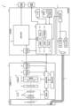
- FIG. 1 is a diagram showing a schematic configuration of an endoscope system according to a first embodiment.
- FIG. 2 is a block diagram showing a functional configuration of a main part of the endoscope system according to the first embodiment.
- FIG. 3 is a diagram illustrating a schematic diagram of wavelength characteristics of excitation light emitted by the light source unit 2 according to the first embodiment.
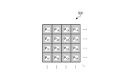
- FIG. 4 is a diagram illustrating a schematic configuration of a pixel unit according to the first embodiment.
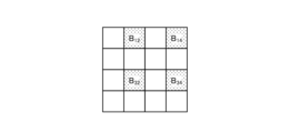
- FIG. 5 is a diagram illustrating a schematic configuration of a color filter according to the first embodiment.
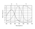
- FIG. 6 is a diagram illustrating the sensitivity and wavelength band of each filter according to the first embodiment.
- FIG. 7A is a diagram illustrating signal values of R pixels of the image sensor according to the first embodiment.
- FIG. 7B is a diagram illustrating signal values of G pixels of the image sensor according to the first embodiment.
- FIG. 7C is a diagram illustrating a signal value of a B pixel of the image sensor according to the first embodiment.
- FIG. 8 is a diagram illustrating a schematic configuration of the cut filter according to the first embodiment.
- FIG. 9 is a diagram illustrating a transmission characteristic of the cut filter according to the first embodiment.
- FIG. 10 is a flowchart showing an outline of the process executed by the control device according to the first embodiment.
- FIG. 11 is a flowchart showing an outline of the process executed by the control device according to the second embodiment.
- FIG. 12 is a diagram showing a schematic configuration of an endoscope system according to the third embodiment.
- FIG. 13 is a block diagram showing a functional configuration of a medical device according to the third embodiment.
- FIG. 1 is a diagram showing a schematic configuration of an endoscope system according to a first embodiment.
- the endoscope system 1 shown in FIG. 1 is used in the medical field and is a system for observing and treating biological tissue in a subject such as a living body.
- a rigid endoscope system using a rigid endoscope (insertion unit 2) shown in FIG. 1 is described as the endoscope system 1, but the present invention is not limited to this, and may be, for example, an endoscope system equipped with a flexible endoscope.
- the endoscope system 1 may be applied to a medical microscope or a medical surgery robot system that includes a medical imaging device that images a subject and performs surgery or processing while displaying an observation image based on an imaging signal (image data) captured by the medical imaging device on a display device.
- a medical imaging device that images a subject and performs surgery or processing while displaying an observation image based on an imaging signal (image data) captured by the medical imaging device on a display device.
- minimally invasive treatments using endoscopes and laparoscopes have become widely used in the medical field.
- minimally invasive treatments using endoscopes and laparoscopes include endoscopic submucosal dissection (ESD), laparoscopy and endoscopic cooperative surgery (LECS), non-exposed endoscopic wall-inversion surgery (NEWS), and transurethral resection of the bladder tumor (TUR-bt).
- a surgeon when a procedure is performed, for example, to mark the area to be operated on as a pre-treatment, a surgeon such as a doctor uses an energy device treatment tool that emits high frequency, ultrasound, microwave, or other energy to perform a marking treatment using cauterization or heat treatment on the area of interest (pathogenic area) that has a lesion on the biological tissue.
- the surgeon also uses an energy device or the like to perform treatments such as ablation and coagulation of the subject's biological tissue.
- the endoscope system 1 shown in FIG. 1 is used when performing surgery or treatment on a subject using a treatment tool (not shown) such as an energy device capable of thermal treatment.
- a treatment tool such as an energy device capable of thermal treatment.
- the endoscope system 1 shown in FIG. 1 is used in transurethral resection of bladder tumor (TUR-Bt) and is used when treating bladder tumors (bladder cancer) and pathogenic areas.
- the endoscope system 1 shown in FIG. 1 includes an insertion section 2, a light source device 3, a light guide 4, an endoscope camera head 5 (an endoscopic imaging device), a first transmission cable 6, a display device 7, a second transmission cable 8, a control device 9, a third transmission cable 10, a perfusion device 11, and a fourth transmission cable 12.
- the insertion section 2 is hard or at least partially soft and has an elongated shape.
- the insertion section 2 is inserted into a subject such as a patient via a trocar.
- the insertion section 2 is provided with an optical system such as a lens that forms an observation image inside.
- the light source device 3 is connected to one end of the light guide 4, and under the control of the control device 9, supplies illumination light to one end of the light guide 4 to be irradiated into the subject.
- the light source device 3 is realized using one or more light sources, such as an LED (Light Emitting Diode) light source, a xenon lamp, or a semiconductor laser element such as an LD (laser diode), a processor which is a processing device having hardware such as an FPGA (Field Programmable Gate Array) or a CPU (Central Processing Unit), and a memory which is a temporary storage area used by the processor.
- the light source device 3 and the control device 9 may be configured to communicate individually as shown in FIG. 1, or may be integrated.
- One end of the light guide 4 is detachably connected to the light source device 3, and the other end is detachably connected to the insertion section 2.
- the light guide 4 guides the illumination light supplied from the light source device 3 from one end to the other, and supplies it to the insertion section 2.
- the endoscopic camera head 5 is detachably connected to the eyepiece 21 of the insertion section 2. Under the control of the control device 9, the endoscopic camera head 5 receives the observation image formed by the insertion section 2 and performs photoelectric conversion to generate an imaging signal (RAW data), and outputs this imaging signal to the control device 9 via the first transmission cable 6.
- RAW data an imaging signal
- the first transmission cable 6 transmits the imaging signal output from the endoscopic camera head 5 to the control device 9, and also transmits setting data, power, etc. output from the control device 9 to the endoscopic camera head 5.
- the setting data refers to a control signal, synchronization signal, clock signal, etc. that controls the endoscopic camera head 5.
- the display device 7 displays an observation image based on an imaging signal that has been subjected to image processing in the control device 9, and various information related to the endoscope system 1.
- the display device 7 is realized using a display monitor such as a liquid crystal or organic EL (Electro Luminescence) display.
- the second transmission cable 8 transmits the imaging signal that has been subjected to image processing in the control device 9 to the display device 7.
- the control device 9 is realized using a processor, which is a processing device having hardware such as a GPU (Graphics Processing Unit), FPGA, or CPU, and a memory, which is a temporary storage area used by the processor.
- the control device 9 comprehensively controls the operation of the light source device 3, the endoscopic camera head 5, and the display device 7 via each of the first transmission cable 6, the second transmission cable 8, and the third transmission cable 10 according to a program recorded in the memory.
- the control device 9 also performs various image processing on the imaging signal input via the first transmission cable 6 and outputs the result to the second transmission cable 8.
- the third transmission cable 10 has one end detachably connected to the light source device 3 and the other end detachably connected to the control device 9.
- the third transmission cable 10 transmits control data from the control device 9 to the light source device 3.
- the perfusion device 11 supplies perfusion fluid, such as sterilized saline, from a fluid supply hole (not shown) in the insertion part 2 through a fluid supply tube (not shown) into the subject's bladder.
- the perfusion device 11 is composed of a fluid supply pump, a drainage pump, a storage tank for storing the perfusion fluid, a waste tank for storing the discharged perfusion fluid, etc.
- the fourth transmission cable 12 has one end detachably connected to the perfusion device 11 and the other end detachably connected to the control device 9.
- the fourth transmission cable 12 transmits control data from the control device 9 to the perfusion device 11.
- Fig. 2 is a block diagram showing the functional configuration of the main parts of the endoscope system 1.
- the insertion portion 2 has an optical system 22 and an illumination optical system 23.
- the optical system 22 forms an image of the subject by collecting light such as reflected light from the subject, return light from the subject, excitation light from the subject, and fluorescence emitted from a thermally denatured region that has been thermally denatured by a thermal treatment such as an energy device.
- the optical system 22 is realized using one or more lenses, etc.
- the illumination optical system 23 irradiates the subject with illumination light supplied from the light guide 4.
- the illumination optical system 23 is realized using one or more lenses, etc.
- the light source device 3 includes a condenser lens 30, a first light source unit 31, a second light source unit 32, and a light source control unit 33.
- the focusing lens 30 focuses the light emitted by each of the first light source unit 31 and the second light source unit 32 and emits the light to the light guide 4.
- the first light source unit 31 emits visible white light (normal light) under the control of the light source control unit 33, thereby supplying white light as illumination light to the light guide 4.
- the first light source unit 31 is configured using a collimator lens, a white LED lamp, a driving driver, etc.
- the first light source unit 31 may supply visible white light by simultaneously emitting light using a red LED lamp, a green LED lamp, and a blue LED lamp.
- the first light source unit 31 may also be configured using a halogen lamp, a xenon lamp, etc.
- the second light source unit 32 emits excitation light having a predetermined wavelength band under the control of the light source control unit 33, and supplies it as illumination light to the light guide 4.
- the excitation light has a wavelength band of 400 nm to 430 nm (center wavelength 415 nm).
- the second light source unit 32 is realized using a collimator lens, a semiconductor laser such as a violet LD (laser diode), and a driving driver.
- the excitation light excites advanced glycation end products that are generated by applying heat treatment to biological tissues using an energy device or the like. However, when amino acids and reducing sugars are heated, a glycation reaction (Maillard reaction) occurs.
- AGEs are characterized by the inclusion of substances with fluorescent properties.
- AGEs are generated by heating the amino acids and reducing sugars in the biological tissue, which causes the Maillard reaction.
- the AGEs generated by this heating can be visualized in the state of heat treatment by fluorescent observation.
- AGEs emit stronger fluorescence than the autofluorescent substances that are originally present in biological tissue. That is, in the first embodiment, the fluorescent properties of AGEs generated in biological tissue by heat treatment with an energy device or the like are used to visualize the thermally denatured area caused by the heat treatment.
- the second light source unit 32 irradiates the biological tissue with blue excitation light with a wavelength of about 415 nm to excite AGEs.
- a fluorescent image thermal denaturation image
- an imaging signal that captures the fluorescence (e.g., green light with a wavelength of 490 to 625 nm) emitted from the thermally denatured area generated by AGEs.
- the light source control unit 33 is realized using a processor having hardware such as an FPGA or a CPU, and a memory that is a temporary storage area used by the processor.
- the light source control unit 33 controls the light emission timing and light emission time of each of the first light source unit 31 and the second light source unit 32 based on control data input from the control device 9.
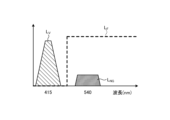
- Fig. 3 is a diagram showing a schematic of the wavelength characteristics of the excitation light emitted by the second light source unit 32.
- the horizontal axis indicates wavelength (nm) and the vertical axis indicates wavelength characteristics.
- the broken line L -V indicates the wavelength characteristics of the excitation light emitted by the second light source unit 32.
- the curve L- B indicates the blue wavelength band
- the curve L- G indicates the green wavelength band
- the curve L- R indicates the red wavelength band.
- the second light source unit 32 emits excitation light having a central wavelength (peak wavelength) of 415 nm and a wavelength band of 400 nm to 430 nm.
- the endoscopic camera head 5 includes an optical system 51, a drive unit 52, an image sensor 53, a cut filter 54, an A/D conversion unit 55, a P/S conversion unit 56, an image capture recording unit 57, and an image capture control unit 58.
- the optical system 51 forms an image of the subject collected by the optical system 22 of the insertion part 2 on the light receiving surface of the image sensor 53.
- the optical system 51 is capable of changing the focal length and focal position.
- the optical system 51 is configured using a plurality of lenses 511.
- the optical system 51 changes the focal length and focal position by moving each of the plurality of lenses 511 on the optical axis L1 using the drive part 52.
- the driving unit 52 moves the multiple lenses 511 of the optical system 51 along the optical axis L1 under the control of the imaging control unit 58.
- the driving unit 52 is configured using a motor such as a stepping motor, a DC motor, or a voice coil motor, and a transmission mechanism such as a gear that transmits the rotation of the motor to the optical system 51.
- the imaging element 53 is realized by using a CCD (Charge Coupled Device) or CMOS (Complementary Metal Oxide Semiconductor) image sensor having multiple pixels arranged in a two-dimensional matrix. Under the control of the imaging control unit 58, the imaging element 53 receives the subject image (light rays) formed by the optical system 51 through the cut filter 54, performs photoelectric conversion to generate an imaging signal (RAW data), and outputs it to the A/D conversion unit 55.
- the imaging element 53 has a pixel unit 531 and a color filter 532.
- Fig. 4 is a diagram showing a schematic configuration of the pixel unit 531.
- the imaging control unit 58 the pixel unit 531 reads out image signals as image data from pixels Pnm in a readout region arbitrarily set as a readout target among the plurality of pixels Pnm , and outputs the image signals to the A/D conversion unit 55.
- FIG. 5 is a diagram showing a schematic configuration of color filter 532.
- color filter 532 is configured in a Bayer array with 2 ⁇ 2 as one unit.
- Color filter 532 is configured using a filter R that transmits light in the red wavelength band, two filters G that transmit light in the green wavelength band, and a filter B that transmits light in the blue wavelength band.
- Fig. 6 is a diagram showing the sensitivity and wavelength band of each filter.
- the horizontal axis indicates wavelength (nm) and the vertical axis indicates transmission characteristics (sensitivity characteristics).
- the curve L- B indicates the transmission characteristics of filter B
- the curve L- G indicates the transmission characteristics of filter G
- the curve L- R indicates the transmission characteristics of filter R.
- the filter B transmits light in the blue wavelength band.
- the filter G transmits light in the green wavelength band.
- the filter R transmits light in the red wavelength band.
- the pixel P- nm having the filter R disposed on the light receiving surface is referred to as the R pixel
- the pixel P -nm having the filter G disposed on the light receiving surface is referred to as the G pixel
- the pixel P -nm having the filter B disposed on the light receiving surface is referred to as the B pixel.
- the image sensor 53 configured in this manner receives the subject image formed by the optical system 51, it generates color signals (R signal, G signal, and B signal) for the R pixel, G pixel, and B pixel, respectively, as shown in Figures 7A to 7C.
- the cut filter 54 is disposed on the optical axis L1 between the optical system 51 and the image sensor 53.
- the cut filter 54 is provided on the light receiving surface side (incident surface side) of the G pixel provided with the filter G that transmits at least the green wavelength band of the color filter 532.
- the cut filter 54 blocks light in a short wavelength band including the wavelength band of the excitation light and transmits a wavelength band longer than the wavelength band of the excitation light.
- Fig. 8 is a diagram showing a schematic configuration of the cut filter 54. As shown in Fig. 8, the filter F11 constituting the cut filter 54 is disposed at the position where the filter G11 (see Fig. 5) is disposed, on the light receiving surface side directly above the filter G11 .
- Fig. 9 is a diagram showing a schematic diagram of the transmission characteristic of the cut filter 54.
- the horizontal axis represents wavelength (nm) and the vertical axis represents the transmission characteristic.
- the broken line L- F represents the transmission characteristic of the cut filter 54
- the broken line L- NG represents the wavelength characteristic of the fluorescent light
- the broken line L- V represents the wavelength characteristic of the excitation light.
- the cut filter 54 blocks the wavelength band of the excitation light and transmits the wavelength band on the longer wavelength side of the wavelength band of the excitation light. Specifically, the cut filter 54 blocks light in the wavelength band on the shorter wavelength side of 400 nm to less than 430 nm, which includes the wavelength band of the excitation light, and transmits light in the wavelength band on the longer wavelength side of 400 nm to 430 nm, which includes the excitation light.
- the A/D conversion unit 55 under the control of the imaging control unit 58, performs A/D conversion processing on the analog imaging signal input from the imaging element 53 and outputs the result to the P/S conversion unit 56.
- the A/D conversion unit 55 is realized using an A/D conversion circuit or the like.
- the P/S conversion unit 56 performs parallel/serial conversion on the digital imaging signal input from the A/D conversion unit 55 under the control of the imaging control unit 58, and outputs the parallel/serial converted imaging signal to the control device 9 via the first transmission cable 6.
- the P/S conversion unit 56 is realized using a P/S conversion circuit or the like. Note that in the first embodiment, instead of the P/S conversion unit 56, an E/O conversion unit that converts the imaging signal into an optical signal may be provided and the imaging signal may be output to the control device 9 by the optical signal, or the imaging signal may be transmitted to the control device 9 by wireless communication such as Wi-Fi (Wireless Fidelity) (registered trademark).
- Wi-Fi Wireless Fidelity
- the imaging and recording unit 57 records various information related to the endoscopic camera head 5 (e.g., pixel information of the imaging element 53, characteristics of the cut filter 54).
- the imaging and recording unit 57 also records various setting data and control parameters transmitted from the control device 9 via the first transmission cable 6.
- the imaging and recording unit 57 is configured using a non-volatile memory and a volatile memory.
- the imaging control unit 58 controls the operation of each of the drive unit 52, the imaging element 53, the A/D conversion unit 55, and the P/S conversion unit 56 based on the setting data received from the control device 9 via the first transmission cable 6.
- the imaging control unit 58 is realized using a TG (Timing Generator), a processor having hardware such as an ASIC (Application Specific Integrated Circuit) or a CPU, and a memory that is a temporary storage area used by the processor.
- the control device 9 includes an S/P conversion unit 91 , an image processing unit 92 , an input unit 93 , a recording unit 94 , and a control unit 95 .
- the S/P conversion unit 91 Under the control of the control unit 95, the S/P conversion unit 91 performs serial/parallel conversion on the image data received from the endoscopic camera head 5 via the first transmission cable 6 and outputs the converted data to the image processing unit 92. If the endoscopic camera head 5 outputs an imaging signal as an optical signal, the S/P conversion unit 91 may be replaced by an O/E conversion unit that converts the optical signal into an electrical signal. If the endoscopic camera head 5 transmits an imaging signal via wireless communication, the S/P conversion unit 91 may be replaced by a communication module capable of receiving wireless signals.
- the image processing unit 92 Under the control of the control unit 95, the image processing unit 92 performs predetermined image processing on the imaging signal of parallel data input from the S/P conversion unit 91 and outputs the result to the display device 7.
- the predetermined image processing includes demosaic processing, white balance processing, gain adjustment processing, gamma correction processing, and format conversion processing.
- the image processing unit 92 is realized using a processor, which is a processing device having hardware such as a GPU or FPGA, and a memory, which is a temporary storage area used by the processor.
- the input unit 93 receives inputs of various operations related to the endoscope system 1 and outputs the received operations to the control unit 95.
- the input unit 93 is configured using a mouse, a foot switch, a keyboard, buttons, switches, a touch panel, etc.
- the recording unit 94 is realized using a recording medium such as a volatile memory, a non-volatile memory, an SSD (Solid State Drive), an HDD (Hard Disk Drive), a memory card, etc.
- the recording unit 94 records data including various parameters necessary for the operation of the endoscope system 1.
- the recording unit 94 also has a program recording unit 941 that records various programs for operating the endoscope system 1.
- the control unit 95 is realized using a processor having hardware such as an FPGA or CPU, and a memory which is a temporary storage area used by the processor.
- the control unit 95 comprehensively controls each component of the endoscope system 1. Specifically, the control unit 95 reads out a program recorded in the program recording unit 941 into a working area of the memory and executes it, and controls each component through the execution of the program by the processor, whereby the hardware and software work together to realize a functional module that meets a specified purpose.
- the control unit 95 has an acquisition unit 951, a decision unit 952, a calculation unit 953, a judgment unit 954, and an output control unit 955.
- the acquisition unit 951 acquires the imaging signal generated by the endoscopic camera head 5 capturing an image via the insertion unit 2.
- the determination unit 952 determines first information contained in the first fluorescence image. Specifically, the determination unit 952 determines the amount of fluorescence of the first fluorescence image as the first information based on pixel values included in the first fluorescence image. The determination unit 952 also determines second information contained in the second fluorescence image. Specifically, the determination unit 952 determines the amount of fluorescence of the second fluorescence image as the second information based on pixel values included in the first fluorescence image.
- the calculation unit 953 calculates the difference between the amount of fluorescence contained in the first fluorescence image determined by the determination unit 952 and the amount of fluorescence contained in the second fluorescence image determined by the determination unit 952. Specifically, the calculation unit 953 calculates the amount of change in the amount of fluorescence over time as the difference, based on the amount of fluorescence contained in the first fluorescence image determined by the determination unit 952 and the amount of fluorescence contained in the second fluorescence image determined by the determination unit 952.
- the determination unit 954 determines whether the difference between the amount of fluorescence contained in the first fluorescence image and the amount of fluorescence contained in the second fluorescence image calculated by the calculation unit 953 is less than a predetermined value. Specifically, the determination unit 954 determines whether the amount of change in the amount of fluorescence calculated by the calculation unit 953 as the difference in the amount of fluorescence is less than a predetermined value.
- the output control unit 955 outputs to the display device 7 a drive signal that causes the display device 7 to display information indicating that the removal of the excised piece has been completed as removal information indicating the removal status of the excised piece within the target area that has been removed by the excision treatment tool.
- the output control unit 955 also outputs to the display device 7 a drive signal that causes the display device 7 to display information indicating that the excised piece is being removed as removal information indicating the removal status of the excised piece within the target area that has been removed by the excision treatment tool.
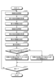
- FIG 10 is a flow chart showing an outline of the process executed by the control device 9.
- control unit 95 causes the second light source unit 32 of the light source device 3 to emit light and supply excitation light to the insertion unit 2, thereby irradiating the excitation light toward the target area of the biological tissue (step S101).
- the acquisition unit 951 acquires the first fluorescent image generated by the endoscopic camera head 5 capturing an image via the insertion portion 2 (step S102).
- the determination unit 952 determines the first information contained in the first fluorescent image (step S103). Specifically, the determination unit 952 determines the amount of fluorescence of the first fluorescent image as the first information based on the pixel values contained in the first fluorescent image.
- control unit 95 causes the second light source unit 32 of the light source device 3 to emit light and supply excitation light to the insertion unit 2, thereby irradiating the excitation light toward the target area of the biological tissue (step S104).
- the acquisition unit 951 acquires a second fluorescent image generated by capturing an image of the target area by the endoscopic camera head 5 via the insertion unit 2 after the time the first fluorescent image was captured (step S105).
- the determination unit 952 determines the second information contained in the second fluorescent image (step S106). Specifically, the determination unit 952 determines the average value of the pixel values of the first fluorescent image and the second fluorescent image as the amount of fluorescence.
- the calculation unit 953 calculates the difference between the amount of fluorescence contained in the first fluorescence image determined by the determination unit 952 and the amount of fluorescence contained in the second fluorescence image determined by the determination unit 952 (step S107). Specifically, the calculation unit 953 calculates the amount of change in the amount of fluorescence over time as the difference based on the amount of fluorescence contained in the first fluorescence image determined by the determination unit 952 and the amount of fluorescence contained in the second fluorescence image determined by the determination unit 952.
- the calculation unit 953 may divide each of the first fluorescence image and the second fluorescence image into a plurality of regions, calculate the average value of the pixel values (amount of fluorescence) of the pixels contained in each of the plurality of regions, and then calculate the amount of change in the amount of fluorescence over time using the average value of the same region in each of the first fluorescence image and the second fluorescence image. Furthermore, the calculation unit 953 may calculate the amount of change in the amount of fluorescence over time from the distribution of the amount of fluorescence in each of the first fluorescence image and the second fluorescence image.
- the determination unit 954 determines whether the amount of change in the amount of fluorescence calculated by the calculation unit 953 is less than a predetermined value (step S108). If the determination unit 954 determines that the amount of change in the amount of fluorescence calculated by the calculation unit 953 is less than the predetermined value (step S108: Yes), the control device 9 proceeds to step S109, which will be described later. On the other hand, if the determination unit 954 determines that the amount of change in the amount of fluorescence calculated by the calculation unit 953 is not less than the predetermined value (step S108: No), the control device 9 proceeds to step S110, which will be described later.
- step S109 the output control unit 955 outputs a drive signal to the display device 7 to cause the display device 7 to display information indicating that removal of the resection piece has been completed as removal information showing the removal status of the resection piece removed by the resection tool within the target area.
- the display device 7 displays information indicating that removal of the resection piece has been completed, such as text, figures, symbols, etc. such as "removal completed", superimposed on the display image input from the image processing unit 92 in accordance with the drive signal input from the control unit 95. This allows the user to know that the resection piece has been removed from the target area.
- step S109 the control device 9 proceeds to step S111, which will be described later.
- step S110 the output control unit 955 outputs a drive signal to the display device 7 to cause the display device 7 to display information indicating that the resection piece is being discharged as discharge information showing the discharge status of the resection piece resected by the resection tool within the target area.
- the display device 7 superimposes characters, figures, symbols, etc. such as "discharging” indicating that the resection piece is being discharged on the display image input from the image processing unit 92 in accordance with the drive signal input from the control unit 95. This allows the user to know that the resection piece has been removed from the target area.
- step S109 the control device 9 proceeds to step S111, which will be described later.
- step S111 the determination unit 954 determines whether or not an end signal to end the observation of the subject by the endoscope system 1 has been input from the input unit 93. If the determination unit 954 determines that an end signal to end the observation of the subject by the endoscope system 1 has been input from the input unit 93 (step S111: Yes), the control device 9 ends this process. On the other hand, if the determination unit 954 determines that an end signal to end the observation of the subject by the endoscope system 1 has not been input from the input unit 93 (step S111: No), the control device 9 returns to the above-mentioned step S101.
- the output control unit 955 outputs a drive signal to the display device 7 to display information indicating that removal of the resected piece has been completed as removal information indicating the removal status of the resected piece removed by the resection treatment tool within the target area, so that the status of the resected piece in the perfusion fluid supplied to the organ can be grasped.
- the output control unit 955 outputs a drive signal to the display device 7 to display information indicating that the resection piece is being discharged as discharge information indicating the discharge status of the resection piece resected by the resection treatment tool within the target area, so that the status of the resection piece in the perfusion fluid can be grasped.
- the motion vector may be calculated based on the first fluorescence image and the second fluorescence image.
- the calculation unit 953 calculates the motion vector based on the difference information between the first fluorescence image and the second fluorescence image.
- the calculation unit 953 calculates the motion vector by referring to a well-known technique for calculating (estimating) optical flow, for example, the Lucas Kanade method or the Horm-Schunk method.
- the determination unit 954 determines that the subject with the large motion vector calculated by the calculation unit 953 is the resection piece, and determines whether or not this motion vector has become less than a predetermined value within the target area. That is, when the motion vector is less than a predetermined value, the determination unit 954 determines that the piece has been removed from the target area, whereas when the motion vector is not less than the predetermined value, the determination unit 954 determines that the piece is being removed from the target area.
- Embodiment 2 Next, a description will be given of embodiment 2.
- the endoscope system according to embodiment 2 has the same configuration as the endoscope system 1 according to embodiment 1 described above, but the processing executed by the control device 9 is different. Specifically, in embodiment 1 described above, a drive signal is output to the display device 7, but in embodiment 2, a drive signal is output to the perfusion device 11. Therefore, hereinafter, the processing executed by the control device provided in the endoscope system according to embodiment 2 will be described.
- FIG. 11 is a flowchart showing an outline of the process executed by the control device 9 according to embodiment 2.
- the control device 9 executes steps S109A and S110A instead of steps S109 and S110 in Fig. 10 described above, and other steps are the same as those described above, so steps S109A and S110A will be described.
- step S109A the output control unit 955 outputs a drive signal to the perfusion device 11 to stop the supply of perfusion fluid as a signal for controlling the perfusion device 11 that supplies perfusion fluid to the target area. This allows the user to concentrate on the treatment of the subject, as they do not need to judge the state of the perfusion fluid based on experience.
- step S109A the control device 9 proceeds to step S111.
- step S110A the output control unit 955 outputs a drive signal to cause the perfusion device 11 to supply perfusion fluid as a signal for controlling the perfusion device 11 that supplies perfusion fluid toward the target area. This causes the perfusion device 11 to supply perfusion fluid toward the target area, allowing the surgeon to discharge to the outside the piece that has been resected by the resection tool.
- step S110A the control device 9 proceeds to step S111.
- the second embodiment described above has the same effect as the first embodiment, that is, it is possible to grasp the state of the resection piece in the irrigation fluid.
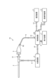
- FIG. 12 is a diagram showing a schematic configuration of an endoscope system according to embodiment 3.
- the endoscope system 1A shown in Fig. 12 includes a control device 9A instead of the control device 9 of the endoscope system 1 according to the above-described embodiment 1.
- the endoscope system 1A further includes a medical device 13 and a fifth transmission cable 14 in addition to the configuration of the endoscope system 1 according to the above-described embodiment 1.
- the control device 9A is realized using a processor, which is a processing device having hardware such as a GPU, FPGA, or CPU, and a memory, which is a temporary storage area used by the processor.
- the control device 9A comprehensively controls the operations of the light source device 3, the endoscopic camera head 5, the display device 7, and the medical device 13 via each of the first transmission cable 6, the second transmission cable 8, the third transmission cable 10, and the fourth transmission cable 12, according to a program recorded in the memory.
- the control device 9A omits the functions of the acquisition unit 951, the determination unit 952, the calculation unit 953, the judgment unit 954, and the output control unit 955 from the control unit 95 according to the above-mentioned first embodiment.
- the medical device 13 is realized using a processor, which is a processing device having hardware such as a GPU, FPGA, or CPU, and a memory, which is a temporary storage area used by the processor.
- the medical device 13 acquires various information from the control device 9A via the fifth transmission cable 14, and outputs the acquired various information to the control device 9A.
- the detailed functional configuration of the medical device 13 will be described later.
- the fifth transmission cable 14 has one end detachably connected to the control device 9A and the other end detachably connected to the medical device 13.
- the fifth transmission cable 14 transmits various information from the control device 9A to the medical device 13 and transmits various information from the medical device 13 to the control device 9A.
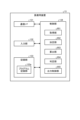
- Fig. 13 is a block diagram showing the functional configuration of the medical device 13.
- the medical device 13 shown in Fig. 16 includes a communication I/F 131, an input unit 132, a recording unit 133, and a control unit 134.
- the communication I/F 131 is an interface for communicating with the control device 9A via the fifth transmission cable 14.
- the communication I/F 131 receives various information from the control device 9A according to a predetermined communication standard, and outputs the received information to the control unit 134.
- the input unit 132 receives input of various operations related to the endoscope system 1A and outputs the received operations to the control unit 134.
- the input unit 132 is configured using a mouse, a foot switch, a keyboard, buttons, switches, a touch panel, etc.
- the recording unit 133 is realized using a recording medium such as a volatile memory, a non-volatile memory, an SSD, an HDD, or a memory card.
- the recording unit 133 records data including various parameters necessary for the operation of the medical device 13.
- the recording unit 133 also has a program recording unit 133a that records various programs for operating the medical device 13.
- the control unit 134 is realized using a processor having hardware such as an FPGA or a CPU, and a memory that is a temporary storage area used by the processor.
- the control unit 134 comprehensively controls each unit that constitutes the medical device 13.
- the control unit 134 has the same functions as the control unit 95 according to the above-mentioned first embodiment. Specifically, the control unit 134 has an acquisition unit 951, a determination unit 952, a calculation unit 953, a judgment unit 954, and an output control unit 955.
- the medical device 13 configured in this manner executes the same processing as the control device 9 according to the first embodiment described above, and outputs the processing results to the control device 9A.
- the control device 9A causes the image processing device 92 to output a display image according to the presence or absence of a light-emitting region within the detection range R1 of the white image generated by the image processing device 92, and causes the display device 7 to display the image.
- the second embodiment described above has the same effect as the first embodiment, and allows the user to check the state of thermal denaturation within a specific region.
- Various inventions can be formed by appropriately combining multiple components disclosed in the endoscope systems according to the above-mentioned embodiments 1 to 3 of the present disclosure. For example, some components may be deleted from all the components described in the endoscope systems according to the above-mentioned embodiments of the present disclosure. Furthermore, the components described in the endoscope systems according to the above-mentioned embodiments of the present disclosure may be appropriately combined.
- the systems are connected to each other by wires, but they may be connected wirelessly via a network.
- the functions of the control unit provided in the endoscope system, and the functional modules of the acquisition unit 951, decision unit 952, calculation unit 953, judgment unit 954, and output control unit 955 may be provided in a server or the like that can be connected via a network.
- a server may be provided for each functional module.
- transurethral bladder tumor resection an example of use in transurethral bladder tumor resection has been described, but the present invention is not limited to this, and can be applied to various procedures, such as resecting lesions using an energy device, etc.
- the "unit" described above can be read as a “means” or a “circuit.”
- a control unit can be read as a control means or a control circuit.
Landscapes
- Health & Medical Sciences (AREA)
- Life Sciences & Earth Sciences (AREA)
- Surgery (AREA)
- Engineering & Computer Science (AREA)
- Nuclear Medicine, Radiotherapy & Molecular Imaging (AREA)
- Medical Informatics (AREA)
- Optics & Photonics (AREA)
- Pathology (AREA)
- Radiology & Medical Imaging (AREA)
- Physics & Mathematics (AREA)
- Veterinary Medicine (AREA)
- Biomedical Technology (AREA)
- Heart & Thoracic Surgery (AREA)
- Biophysics (AREA)
- Molecular Biology (AREA)
- Animal Behavior & Ethology (AREA)
- General Health & Medical Sciences (AREA)
- Public Health (AREA)
- Urology & Nephrology (AREA)
- Signal Processing (AREA)
- Endoscopes (AREA)
Abstract
Priority Applications (3)
| Application Number | Priority Date | Filing Date | Title |
|---|---|---|---|
| CN202380093328.XA CN120641022A (zh) | 2023-02-09 | 2023-02-09 | 医疗用装置、医疗用系统、医疗用装置的工作方法以及程序 |
| PCT/JP2023/004454 WO2024166327A1 (fr) | 2023-02-09 | 2023-02-09 | Dispositif médical, système médical, procédé d'utilisation de dispositif médical, et programme |
| US19/289,503 US20250352049A1 (en) | 2023-02-09 | 2025-08-04 | Medical device, medical system, method of operating medical device, and computer-readable recording medium |
Applications Claiming Priority (1)
| Application Number | Priority Date | Filing Date | Title |
|---|---|---|---|
| PCT/JP2023/004454 WO2024166327A1 (fr) | 2023-02-09 | 2023-02-09 | Dispositif médical, système médical, procédé d'utilisation de dispositif médical, et programme |
Related Child Applications (1)
| Application Number | Title | Priority Date | Filing Date |
|---|---|---|---|
| US19/289,503 Continuation US20250352049A1 (en) | 2023-02-09 | 2025-08-04 | Medical device, medical system, method of operating medical device, and computer-readable recording medium |
Publications (1)
| Publication Number | Publication Date |
|---|---|
| WO2024166327A1 true WO2024166327A1 (fr) | 2024-08-15 |
Family
ID=92262138
Family Applications (1)
| Application Number | Title | Priority Date | Filing Date |
|---|---|---|---|
| PCT/JP2023/004454 Ceased WO2024166327A1 (fr) | 2023-02-09 | 2023-02-09 | Dispositif médical, système médical, procédé d'utilisation de dispositif médical, et programme |
Country Status (3)
| Country | Link |
|---|---|
| US (1) | US20250352049A1 (fr) |
| CN (1) | CN120641022A (fr) |
| WO (1) | WO2024166327A1 (fr) |
Citations (3)
| Publication number | Priority date | Publication date | Assignee | Title |
|---|---|---|---|---|
| US20160038027A1 (en) * | 2006-10-06 | 2016-02-11 | Novadaq Technologies Inc. | Methods, software and systems for imaging |
| WO2020174666A1 (fr) * | 2019-02-28 | 2020-09-03 | オリンパス株式会社 | Système médical |
| JP2021528210A (ja) * | 2018-06-14 | 2021-10-21 | パーフュージョン テック アーペーエス | 自動灌流測定のためのシステム及び方法 |
-
2023
- 2023-02-09 CN CN202380093328.XA patent/CN120641022A/zh active Pending
- 2023-02-09 WO PCT/JP2023/004454 patent/WO2024166327A1/fr not_active Ceased
-
2025
- 2025-08-04 US US19/289,503 patent/US20250352049A1/en active Pending
Patent Citations (3)
| Publication number | Priority date | Publication date | Assignee | Title |
|---|---|---|---|---|
| US20160038027A1 (en) * | 2006-10-06 | 2016-02-11 | Novadaq Technologies Inc. | Methods, software and systems for imaging |
| JP2021528210A (ja) * | 2018-06-14 | 2021-10-21 | パーフュージョン テック アーペーエス | 自動灌流測定のためのシステム及び方法 |
| WO2020174666A1 (fr) * | 2019-02-28 | 2020-09-03 | オリンパス株式会社 | Système médical |
Also Published As
| Publication number | Publication date |
|---|---|
| CN120641022A (zh) | 2025-09-12 |
| US20250352049A1 (en) | 2025-11-20 |
Similar Documents
| Publication | Publication Date | Title |
|---|---|---|
| US20230000330A1 (en) | Medical observation system, medical imaging device and imaging method | |
| US20230248209A1 (en) | Assistant device, endoscopic system, assistant method, and computer-readable recording medium | |
| US12121219B2 (en) | Medical image processing device, medical imaging device, medical observation system, image processing method, and computer-readable recording medium | |
| WO2024166327A1 (fr) | Dispositif médical, système médical, procédé d'utilisation de dispositif médical, et programme | |
| JP5764472B2 (ja) | 内視鏡診断装置 | |
| WO2024166310A1 (fr) | Dispositif médical, système médical, dispositif d'apprentissage, procédé d'utilisation de dispositif médical, et programme | |
| WO2024166330A1 (fr) | Dispositif médical, système médical, procédé de fonctionnement de dispositif médical et programme | |
| WO2024166308A1 (fr) | Dispositif médical, système médical, dispositif d'apprentissage, procédé d'utilisation de dispositif médical, et programme | |
| US20250352026A1 (en) | Medical device, medical system, operation method of medical device, and computer-readable recording medium | |
| US20250356490A1 (en) | Assistance device, operation method of assistance device, computer-readable recording medium, medical system, and learning device | |
| US20250359741A1 (en) | Medical device, medical system, medical device operation method, and computer-readable recording medium | |
| US20250352028A1 (en) | Medical device, medical system, learning device, method of operating medical device, and computer-readable recording medium | |
| US20250359728A1 (en) | Control device, medical system, operation method of medical device, and computer-readable recording medium | |
| US20230210354A1 (en) | Assist device, endoscope system, assist method and computer-readable recording medium | |
| WO2024166325A1 (fr) | Dispositif médical, système d'endoscope, procédé de commande, programme de commande et dispositif d'apprentissage | |
| US20250352273A1 (en) | Image processing apparatus, medical system, operation method of image processing apparatus, and learning apparatus | |
| WO2024166311A1 (fr) | Dispositif de traitement d'image, système médical, procédé de fonctionnement de dispositif de traitement d'image et dispositif d'apprentissage |
Legal Events
| Date | Code | Title | Description |
|---|---|---|---|
| 121 | Ep: the epo has been informed by wipo that ep was designated in this application |
Ref document number: 23921158 Country of ref document: EP Kind code of ref document: A1 |
|
| WWE | Wipo information: entry into national phase |
Ref document number: 202380093328.X Country of ref document: CN |
|
| NENP | Non-entry into the national phase |
Ref country code: DE |
|
| WWP | Wipo information: published in national office |
Ref document number: 202380093328.X Country of ref document: CN |
|
| 122 | Ep: pct application non-entry in european phase |
Ref document number: 23921158 Country of ref document: EP Kind code of ref document: A1 |