WO2024166311A1 - Dispositif de traitement d'image, système médical, procédé de fonctionnement de dispositif de traitement d'image et dispositif d'apprentissage - Google Patents
Dispositif de traitement d'image, système médical, procédé de fonctionnement de dispositif de traitement d'image et dispositif d'apprentissage Download PDFInfo
- Publication number
- WO2024166311A1 WO2024166311A1 PCT/JP2023/004406 JP2023004406W WO2024166311A1 WO 2024166311 A1 WO2024166311 A1 WO 2024166311A1 JP 2023004406 W JP2023004406 W JP 2023004406W WO 2024166311 A1 WO2024166311 A1 WO 2024166311A1
- Authority
- WO
- WIPO (PCT)
- Prior art keywords
- image
- region
- processing device
- image processing
- pixel
- Prior art date
- Legal status (The legal status is an assumption and is not a legal conclusion. Google has not performed a legal analysis and makes no representation as to the accuracy of the status listed.)
- Ceased
Links
Images


Classifications
-
- G—PHYSICS
- G06—COMPUTING OR CALCULATING; COUNTING
- G06V—IMAGE OR VIDEO RECOGNITION OR UNDERSTANDING
- G06V10/00—Arrangements for image or video recognition or understanding
- G06V10/40—Extraction of image or video features
- G06V10/60—Extraction of image or video features relating to illumination properties, e.g. using a reflectance or lighting model
-
- A—HUMAN NECESSITIES
- A61—MEDICAL OR VETERINARY SCIENCE; HYGIENE
- A61B—DIAGNOSIS; SURGERY; IDENTIFICATION
- A61B1/00—Instruments for performing medical examinations of the interior of cavities or tubes of the body by visual or photographical inspection, e.g. endoscopes; Illuminating arrangements therefor
- A61B1/00002—Operational features of endoscopes
- A61B1/00004—Operational features of endoscopes characterised by electronic signal processing
- A61B1/00009—Operational features of endoscopes characterised by electronic signal processing of image signals during a use of endoscope
- A61B1/000094—Operational features of endoscopes characterised by electronic signal processing of image signals during a use of endoscope extracting biological structures
-
- A—HUMAN NECESSITIES
- A61—MEDICAL OR VETERINARY SCIENCE; HYGIENE
- A61B—DIAGNOSIS; SURGERY; IDENTIFICATION
- A61B1/00—Instruments for performing medical examinations of the interior of cavities or tubes of the body by visual or photographical inspection, e.g. endoscopes; Illuminating arrangements therefor
- A61B1/00002—Operational features of endoscopes
- A61B1/00004—Operational features of endoscopes characterised by electronic signal processing
- A61B1/00009—Operational features of endoscopes characterised by electronic signal processing of image signals during a use of endoscope
- A61B1/000096—Operational features of endoscopes characterised by electronic signal processing of image signals during a use of endoscope using artificial intelligence
-
- A—HUMAN NECESSITIES
- A61—MEDICAL OR VETERINARY SCIENCE; HYGIENE
- A61B—DIAGNOSIS; SURGERY; IDENTIFICATION
- A61B1/00—Instruments for performing medical examinations of the interior of cavities or tubes of the body by visual or photographical inspection, e.g. endoscopes; Illuminating arrangements therefor
- A61B1/04—Instruments for performing medical examinations of the interior of cavities or tubes of the body by visual or photographical inspection, e.g. endoscopes; Illuminating arrangements therefor combined with photographic or television appliances
- A61B1/043—Instruments for performing medical examinations of the interior of cavities or tubes of the body by visual or photographical inspection, e.g. endoscopes; Illuminating arrangements therefor combined with photographic or television appliances for fluorescence imaging
-
- A—HUMAN NECESSITIES
- A61—MEDICAL OR VETERINARY SCIENCE; HYGIENE
- A61B—DIAGNOSIS; SURGERY; IDENTIFICATION
- A61B1/00—Instruments for performing medical examinations of the interior of cavities or tubes of the body by visual or photographical inspection, e.g. endoscopes; Illuminating arrangements therefor
- A61B1/06—Instruments for performing medical examinations of the interior of cavities or tubes of the body by visual or photographical inspection, e.g. endoscopes; Illuminating arrangements therefor with illuminating arrangements
- A61B1/0638—Instruments for performing medical examinations of the interior of cavities or tubes of the body by visual or photographical inspection, e.g. endoscopes; Illuminating arrangements therefor with illuminating arrangements providing two or more wavelengths
-
- A—HUMAN NECESSITIES
- A61—MEDICAL OR VETERINARY SCIENCE; HYGIENE
- A61B—DIAGNOSIS; SURGERY; IDENTIFICATION
- A61B5/00—Measuring for diagnostic purposes; Identification of persons
- A61B5/0033—Features or image-related aspects of imaging apparatus, e.g. for MRI, optical tomography or impedance tomography apparatus; Arrangements of imaging apparatus in a room
-
- A—HUMAN NECESSITIES
- A61—MEDICAL OR VETERINARY SCIENCE; HYGIENE
- A61B—DIAGNOSIS; SURGERY; IDENTIFICATION
- A61B5/00—Measuring for diagnostic purposes; Identification of persons
- A61B5/0059—Measuring for diagnostic purposes; Identification of persons using light, e.g. diagnosis by transillumination, diascopy, fluorescence
- A61B5/0071—Measuring for diagnostic purposes; Identification of persons using light, e.g. diagnosis by transillumination, diascopy, fluorescence by measuring fluorescence emission
-
- G—PHYSICS
- G06—COMPUTING OR CALCULATING; COUNTING
- G06T—IMAGE DATA PROCESSING OR GENERATION, IN GENERAL
- G06T5/00—Image enhancement or restoration
- G06T5/50—Image enhancement or restoration using two or more images, e.g. averaging or subtraction
-
- G—PHYSICS
- G06—COMPUTING OR CALCULATING; COUNTING
- G06T—IMAGE DATA PROCESSING OR GENERATION, IN GENERAL
- G06T7/00—Image analysis
- G06T7/0002—Inspection of images, e.g. flaw detection
- G06T7/0012—Biomedical image inspection
-
- A—HUMAN NECESSITIES
- A61—MEDICAL OR VETERINARY SCIENCE; HYGIENE
- A61B—DIAGNOSIS; SURGERY; IDENTIFICATION
- A61B1/00—Instruments for performing medical examinations of the interior of cavities or tubes of the body by visual or photographical inspection, e.g. endoscopes; Illuminating arrangements therefor
- A61B1/00002—Operational features of endoscopes
- A61B1/00043—Operational features of endoscopes provided with output arrangements
- A61B1/00045—Display arrangement
- A61B1/0005—Display arrangement combining images e.g. side-by-side, superimposed or tiled
-
- G—PHYSICS
- G06—COMPUTING OR CALCULATING; COUNTING
- G06T—IMAGE DATA PROCESSING OR GENERATION, IN GENERAL
- G06T2207/00—Indexing scheme for image analysis or image enhancement
- G06T2207/10—Image acquisition modality
- G06T2207/10064—Fluorescence image
-
- G—PHYSICS
- G06—COMPUTING OR CALCULATING; COUNTING
- G06T—IMAGE DATA PROCESSING OR GENERATION, IN GENERAL
- G06T2207/00—Indexing scheme for image analysis or image enhancement
- G06T2207/20—Special algorithmic details
- G06T2207/20212—Image combination
- G06T2207/20221—Image fusion; Image merging
-
- G—PHYSICS
- G06—COMPUTING OR CALCULATING; COUNTING
- G06T—IMAGE DATA PROCESSING OR GENERATION, IN GENERAL
- G06T2207/00—Indexing scheme for image analysis or image enhancement
- G06T2207/30—Subject of image; Context of image processing
- G06T2207/30004—Biomedical image processing
- G06T2207/30101—Blood vessel; Artery; Vein; Vascular
Definitions
- the present invention relates to an image processing device, a medical system, an operation method of an image processing device, and a learning device.
- ESD endoscopic submucosal dissection
- ESD the periphery of the diseased area of biological tissue is removed with an energy device such as a high-frequency knife.
- an energy device such as a high-frequency knife.
- AGEs advanced glycation end products
- AGEs emit fluorescence when irradiated with excitation light, so the state of the thermal treatment can be visualized using a fluorescent image (see, for example, Patent Document 1).
- the surgeon then performs hemostasis treatment by thermal coagulation on the removed area while observing the fluorescent image.
- the present invention has been made in consideration of the above, and aims to provide an image processing device, a medical system, an operating method of an image processing device, and a learning device that can easily recognize areas where hemostatic treatment is insufficient.
- an image processing device is an image processing device equipped with a processor having hardware, in which the processor obtains a fluorescence image by irradiating excitation light onto biological tissue and capturing fluorescence, extracts a first pixel in the fluorescence image having a brightness value equal to or greater than a first threshold, identifies a first region based on position information of the first pixel, extracts a second pixel in the first region of the fluorescence image having a brightness value equal to or less than a second threshold, identifies a second region based on position information of the second pixel, and outputs information in which the second region is superimposed on the fluorescence image.
- the first threshold value is greater than the second threshold value.
- the fluorescence image is an image obtained by capturing the fluorescence generated from a thermally denatured region of the biological tissue.
- the thermally denatured region is formed by applying heat treatment to the biological tissue using an energy device.
- the first threshold value and the second threshold value are set according to the brightness value of the fluorescence generated from advanced glycation end products that are generated by thermal denaturation of the biological tissue.
- the processor outputs information in which the first region is superimposed on the fluorescence image.
- the processor outputs information in which the second region is superimposed on a white light image obtained by irradiating the biological tissue with white light and capturing the return light.
- the processor outputs information in which the first region is superimposed on a white light image obtained by irradiating the biological tissue with white light and capturing the return light.
- the processor identifies a circular area formed by connecting the first pixels as the first area.
- a medical system includes a light source device that irradiates excitation light onto biological tissue, an endoscope having an image sensor that outputs an image signal capturing fluorescence due to the excitation light, and an image processing device having a processor that generates a fluorescent image from the image signal, in which the processor extracts first pixels having a luminance value equal to or greater than a first threshold value in the fluorescent image, identifies a first region based on position information of the first pixels, extracts second pixels having a luminance value equal to or less than a second threshold value within the first region of the fluorescent image, identifies a second region based on position information of the second pixels, and outputs information in which the second region is superimposed on the fluorescent image.
- Another aspect of the present invention is a method for operating an image processing device that includes a processor having hardware, in which the processor obtains a fluorescence image by irradiating biological tissue with excitation light and capturing fluorescence, extracts a first pixel in the fluorescence image that has a brightness value equal to or greater than a first threshold, identifies a first region based on position information of the first pixel, extracts a second pixel in the first region of the fluorescence image that has a brightness value equal to or less than a second threshold, identifies a second region based on position information of the second pixel, and outputs information in which the second region is superimposed on the fluorescence image.
- a learning device includes a learning unit that generates a trained model by machine learning using training data in which a fluorescent image obtained by irradiating excitation light onto biological tissue and capturing fluorescence is used as input data, and in which output data is information obtained by superimposing on the fluorescent image a second region identified based on positional information of a second pixel whose luminance value is equal to or less than a second threshold within a first region identified based on a first pixel whose luminance value is equal to or greater than a first threshold in the fluorescent image.
- the present invention provides an image processing device, a medical system, an operating method for an image processing device, and a learning device that can easily recognize areas where hemostasis treatment is insufficient.
- FIG. 1 is a diagram illustrating a schematic diagram of an overall configuration of an endoscope system according to an embodiment.
- FIG. 2 is a block diagram showing a functional configuration of a main part of an endoscope system according to an embodiment.
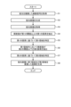
- FIG. 3 is a flowchart showing an outline of the process executed by the control device.
- FIG. 4 is an example of a fluorescent image.
- FIG. 5 is a diagram showing how the second region is superimposed on the fluorescent image.
- FIG. 6 is a diagram showing how a second region is superimposed on a white light image.
- an endoscopic system having an endoscope with a flexible insertion section will be described, but the present disclosure is not limited to this and can also be applied to, for example, rigid endoscopes and surgical robots. Furthermore, the present disclosure is not limited to this embodiment. Furthermore, in describing the drawings, identical parts are denoted by the same reference numerals. Furthermore, it should be noted that the drawings are schematic, and the relationship between the thickness and width of each component, the ratio of each component, etc., differ from reality. Furthermore, the drawings include parts with different dimensions and ratios.
- FIG. 1 is a diagram showing a schematic diagram of an overall configuration of an endoscope system according to an embodiment.
- the endoscope system 1 shown in Fig. 1 captures images of the inside of a subject's body by inserting an insertion portion of an endoscope into a body cavity or lumen of the subject, such as a patient, and displays an image based on the captured image signal on a display device.
- the endoscope system 1 includes an endoscope 2, a light source device 3, a control device 4 as an image processing device, and a display device 5.
- the endoscope 2 generates an imaging signal (RAW data) by imaging the inside of the subject's body, and outputs the generated imaging signal to the control device 4. Specifically, the endoscope 2 generates a first imaging signal by irradiating white light and imaging return light, and a second imaging signal by irradiating excitation light and imaging fluorescence.
- the endoscope 2 includes an insertion section 21, an operation section 22, and a universal cord 23.
- the insertion section 21 is inserted into the subject.
- the insertion section 21 has a flexible, elongated shape.
- the insertion section 21 has a tip section 24 that incorporates an imaging element (described later), a freely bendable bending section 25 composed of multiple bending pieces, and a long, flexible flexible tube section 26 that is connected to the base end side of the bending section 25.
- the tip 24 is made of glass fiber or the like.
- the tip 24 forms a light guide path for the illumination light supplied from the control device 4 via the universal cord 23 and the operation unit 22, and also generates an image signal capturing the return light of the illumination light and outputs it to the control device 4.
- the operation unit 22 has a bending knob 221 for bending the bending portion 25 in the up-down and left-right directions, a treatment tool insertion portion 222 for inserting a treatment tool, and a number of switches 223 which are operation input portions for inputting, in addition to the control device 4, operation instruction signals for peripheral devices such as an air supply means, a water supply means, and a gas supply means, a pre-freeze signal for instructing the endoscope system 1 to take still images, or a switching signal for switching the observation mode of the endoscope system 1.
- the treatment tool inserted from the treatment tool insertion portion 222 emerges from the opening via the treatment tool channel of the tip portion 24.
- the universal cord 23 incorporates at least a light guide and a light collecting cable consisting of one or more cables.
- the collecting cable is a signal line for transmitting and receiving signals between the endoscope 2 and the control device 4, and includes a signal line for transmitting and receiving an imaging signal (RAW data) and a signal line for transmitting and receiving a timing signal (synchronization signal and clock signal) for driving the imaging element described below.
- the universal cord 23 has a connector section 27 that is detachable from the control device 4, and a connector section 28 at the extended end of the coiled cable 27a that is detachable from the control device 4.
- the light source device 3 irradiates living tissue with white light and excitation light as illumination light.
- One end of the light guide of the endoscope 2 is connected to the light source device 3, and the light source device 3 supplies illumination light to be irradiated into the subject to the one end of the light guide under the control of the control device 4.
- the light source device 3 is realized using one or more light sources, such as an LED (Light Emitting Diode) light source, a xenon lamp, and a semiconductor laser element such as an LD (Laser Diode), a processor that is a processing device having hardware such as an FPGA (Field Programmable Gate Array) and a CPU (Central Processing Unit), and a memory that is a temporary storage area used by the processor.
- the light source device 3 and the control device 4 may be configured to communicate individually as shown in FIG. 1, or may be configured as an integrated device.
- the control device 4 controls each component of the endoscope system 1.
- the control device 4 controls the light source device 3 to supply illumination light for the endoscope 2 to irradiate the subject.
- the control device 4 also performs various image processing on the imaging signal input from the endoscope 2 and outputs the signal to the display device 5.
- the display device 5 under the control of the control device 4, displays an image based on a video signal input from the control device 4.
- the display device 5 is realized using a display panel such as an organic EL (Electro Luminescence) panel or a liquid crystal panel.
- Fig. 2 is a block diagram showing the functional configuration of the main parts of the endoscope system 1.
- the endoscope 2 includes an illumination optical system 201, an imaging optical system 202, a cut filter 203, an imaging element 204, an A/D conversion unit 205, a P/S conversion unit 206, an imaging recording unit 207, and an imaging control unit 208.
- Each of the illumination optical system 201, the imaging optical system 202, the cut filter 203, the imaging element 204, the A/D conversion unit 205, the P/S conversion unit 206, the imaging recording unit 207, and the imaging control unit 208 is disposed in the tip portion 24.
- the illumination optical system 201 irradiates the subject (biological tissue) with illumination light supplied from a light guide 231 formed of an optical fiber or the like.
- the illumination optical system 201 is realized using one or more lenses or the like.
- the imaging optical system 202 focuses light such as reflected light from the subject, return light from the subject, and fluorescence emitted by the subject, to form an image of the subject (light rays) on the light receiving surface of the image sensor 204.
- the imaging optical system 202 is realized using one or more lenses, etc.
- the cut filter 203 is disposed on the optical axis O1 between the imaging optical system 202 and the imaging element 204.
- the cut filter 203 blocks light in the wavelength band of the excitation light supplied from the light source device 3, which is reflected or returned from the subject, and transmits light in a wavelength band longer than the wavelength band of the excitation light.
- the imaging element 204 Under the control of the imaging control unit 208, the imaging element 204 receives the subject image (light rays) formed by the imaging optical system 202 and transmitted through the cut filter 203, performs photoelectric conversion to generate an imaging signal (RAW data), and outputs it to the A/D conversion unit 205.
- the imaging element 204 is realized using a CCD (Charge Coupled Device) or CMOS (Complementary Metal Oxide Semiconductor) image sensor in which one of the color filters constituting a Bayer array (RGGB) is arranged on each of a plurality of pixels arranged in a two-dimensional matrix.
- CCD Charge Coupled Device
- CMOS Complementary Metal Oxide Semiconductor
- the A/D conversion unit 205 Under the control of the imaging control unit 208, the A/D conversion unit 205 performs A/D conversion processing on the analog imaging signal input from the imaging element 204 and outputs the result to the P/S conversion unit 206.
- the A/D conversion unit 205 is realized using an A/D conversion circuit, etc.
- the P/S conversion unit 206 performs parallel/serial conversion on the digital imaging signal input from the A/D conversion unit 205 under the control of the imaging control unit 208, and outputs the parallel/serial converted imaging signal to the control device 4 via the first transmission cable 232.
- the P/S conversion unit 206 is realized using a P/S conversion circuit or the like. Note that in the first embodiment, instead of the P/S conversion unit 206, an E/O conversion unit that converts the imaging signal into an optical signal may be provided, and the imaging signal may be output to the control device 4 by the optical signal, or the imaging signal may be transmitted to the control device 4 by wireless communication such as Wi-Fi (Wireless Fidelity) (registered trademark).
- Wi-Fi Wireless Fidelity
- the imaging and recording unit 207 records various information related to the endoscope 2 (e.g., pixel information of the imaging element 204, characteristics of the cut filter 203).
- the imaging and recording unit 207 also records various setting data and control parameters transmitted from the control device 4 via the second transmission cable 233.
- the imaging and recording unit 207 is configured using a non-volatile memory and a volatile memory.
- the imaging control unit 208 controls the operation of the imaging element 204, the A/D conversion unit 205, and the P/S conversion unit 206 based on the setting data received from the control device 4 via the second transmission cable 233.
- the imaging control unit 208 is realized using a TG (Timing Generator), a processor which is a processing device having hardware such as a CPU, and a memory which is a temporary storage area used by the processor.
- the light source device 3 includes a condenser lens 30 , a first light source unit 31 , a second light source unit 32 , and a light source control unit 33 .
- the focusing lens 30 focuses the light emitted by each of the first light source unit 31 and the second light source unit 32 and emits the light to the light guide 231.
- the focusing lens 30 is composed of one or more lenses.
- the first light source unit 31 emits visible white light (normal light) under the control of the light source control unit 33, thereby supplying the white light as illumination light to the light guide 231.
- the first light source unit 31 is configured using a collimator lens, a white LED lamp, a driving driver, etc.
- the first light source unit 31 may supply visible white light by simultaneously emitting light using a red LED lamp, a green LED lamp, and a blue LED lamp.
- the first light source unit 31 may also be configured using a halogen lamp, a xenon lamp, etc.
- the second light source unit 32 emits excitation light having a predetermined wavelength band under the control of the light source control unit 33, thereby supplying the excitation light as illumination light to the light guide 231.
- the excitation light has a wavelength that excites substances such as advanced glycation end products (AGEs) contained in the thermally denatured region, and has a wavelength band of 400 nm to 430 nm (center wavelength 415 nm), for example.
- the thermally denatured region is a region in which biological tissue is denatured by heat as a result of thermal treatment performed by an energy device such as a high-frequency knife.
- the excitation light irradiated by the second light source unit 32 is blocked by the cut filter 203, and the fluorescence (wavelength 540 nm) generated from the AGEs passes through the cut filter 203, so that a fluorescent image can be captured.
- the second light source unit 32 is realized using a collimating lens, a semiconductor laser such as a violet LD (Laser Diode), a driver, etc.
- the light source control unit 33 is configured using a processor, which is a processing device having hardware such as an FPGA (Field-Programmable Gate Array) or a CPU (Central Processing Unit), and a memory, which is a temporary storage area used by the processor.
- the light source control unit 33 controls the light emission timing, light emission intensity, light emission time, etc. of each of the first light source unit 31 and the second light source unit 32 based on control data input from the control unit 405.
- the control device 4 includes an S/P conversion unit 401 , an image processing unit 402 , an input unit 403 , a recording unit 404 , and a control unit 405 .
- the S/P conversion unit 401 performs serial/parallel conversion on the imaging signal received from the endoscope 2 via the first transmission cable 232 and outputs it to the image processing unit 402.
- the endoscope 2 outputs the imaging signal as an optical signal
- an O/E conversion unit that converts the optical signal into an electrical signal may be provided instead of the S/P conversion unit 401.
- a communication module capable of receiving wireless signals may be provided instead of the S/P conversion unit 401.
- the image processing unit 402 is realized using a processor having hardware such as a CPU, a GPU (Graphics Processing Unit) or an FPGA, and a memory which is a temporary storage area used by the processor. Under the control of the control unit 405, the image processing unit 402 performs a predetermined image processing on the imaging signal input from the S/P conversion unit 401 and outputs the result to the display device 5.
- the image processing unit 402 generates a white light image from the first imaging signal and generates a fluorescent image from the second imaging signal.
- the image processing unit 402 has an image generation unit 402a, an acquisition unit 402b, an extraction unit 402c, an identification unit 402d, and an output unit 402e.
- the image generating unit 402a generates a white light image from a first imaging signal obtained by irradiating white light from the first light source unit 31 onto biological tissue and capturing the return light.
- the image generating unit 402a also generates a fluorescent image from a second imaging signal obtained by irradiating excitation light from the second light source unit 32 onto biological tissue and capturing the fluorescent light.
- the acquisition unit 402b acquires a white light image and a fluorescent image from the image generation unit 402a.
- the acquisition unit 402b also acquires a first imaging signal and a second imaging signal from the endoscope 2.
- the extraction unit 402c extracts a first pixel in the fluorescence image whose luminance value is equal to or greater than a first threshold.
- the extraction unit 402c also extracts a second pixel in the first region of the fluorescence image whose luminance value is equal to or less than a second threshold.
- the first threshold is greater than the second threshold.
- the identification unit 402d identifies the first region as a circular region formed by connecting the first pixels based on the position information of the first pixels.
- the identification unit 402d also identifies the second region based on the position information of the second pixels.
- the output unit 402e outputs information in which the first region and the second region are superimposed on the fluorescent image.
- the output unit 402e may also output information in which the first region and the second region are superimposed on the white light image.
- the input unit 403 receives inputs of various operations related to the endoscope system 1 and outputs the received operations to the control unit 405.
- the input unit 403 is configured using a mouse, a foot switch, a keyboard, buttons, switches, a touch panel, etc.
- the recording unit 404 is realized using a recording medium such as a volatile memory, a non-volatile memory, an SSD (Solid State Drive), an HDD (Hard Disk Drive), or a memory card.
- the recording unit 404 records data including various parameters necessary for the operation of the endoscope system 1.
- the recording unit 404 stores, for example, position information of the first pixel and the second pixel, position information of the first region and the second region, etc.
- the recording unit 404 also has a program recording unit 404a that records various programs for operating the endoscope system 1.
- the control unit 405 is realized using a processor having hardware such as an FPGA or a CPU, and a memory that is a temporary storage area used by the processor.
- the control unit 405 comprehensively controls each part that constitutes the endoscope system 1.
- FIG. 3 is a flowchart showing an outline of the process executed by the control device 10.
- the acquisition unit 402b acquires a second imaging signal obtained by irradiating a living tissue with excitation light from the second light source unit 32 and capturing an image of fluorescence (step S1).
- the image generating unit 402a generates a fluorescent image from the second imaging signal acquired by the acquiring unit 402b (step S2).
- the fluorescent image generated by the image generating unit 402a is stored in the recording unit 404.
- the acquisition unit 402b acquires the fluorescence image from the recording unit 404 (step S3).
- the acquisition unit 402b may acquire the fluorescence image from an external server via an Internet line.
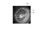
- FIG 4 is an example of a fluorescence image.
- Fluorescence image FI1 shown in Figure 4 is an image capturing the fluorescence generated by a thermally denatured region in biological tissue.
- the thermally denatured region is formed by subjecting biological tissue to heat treatment using an energy device, and contains AGEs (advanced glycation end products).
- AGEs advanced glycation end products
- ESD ESD
- AGEs generate fluorescence when irradiated with excitation light, so it can be seen that the area corresponding to the periphery of the lesion in the fluorescence image FI1 is white and roughly circular.
- the extraction unit 402c extracts a first pixel in the fluorescence image FI1 whose brightness value is equal to or greater than a first threshold value (step S4). This makes it possible to extract the portion of the fluorescence image FI1 that has a high brightness value and was removed with the energy device.
- the identification unit 402d identifies the first region as a circular region formed by connecting the first pixels based on the position information of the first pixels (step S5). By connecting parts with high brightness values in the fluorescence image FI1, it is possible to identify the circular first region indicated by the dashed line L1. Note that the first region is the entire area inside the dashed line L1.
- the extraction unit 402c extracts second pixels in the first region of the fluorescence image FI1 whose brightness values are equal to or less than the second threshold value (step S6). This makes it possible to extract parts of the fluorescence image FI1 that have low brightness values and are insufficiently heat-treated.
- the identification unit 402d identifies a second region based on the position information of the second pixel (step S7). It is possible to identify the second region indicated by the solid line L2 in the fluorescence image FI1, which has a low brightness value.
- the output unit 402e outputs information in which the first region and the second region are superimposed on the fluorescence image FI1 (step S8).
- the dashed line L1 indicating the first region and the solid line L2 indicating the second region are superimposed on the fluorescence image FI1 shown in FIG. 4 is displayed on the display device 5.
- the solid line L2 indicating the second area is superimposed on the fluorescence image FI1, allowing the surgeon to easily recognize areas where hemostasis treatment is insufficient.
- the display on the display device 5 switches from a white light image to a fluorescent image FI1 superimposed with a solid line L2 indicating the second region in Figure 4, and the surgeon can observe the fluorescent image FI1.
- the surgeon then performs hemostasis treatment using the energy device while checking the condition of the second region. As a result, it is possible to prevent insufficient hemostasis treatment during ESD.
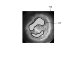
- FIG. 5 is a diagram showing how the second region is superimposed on the fluorescence image. As shown in Fig. 5, the second region A1 may be superimposed on the fluorescence image FI2 by filling it with a specific color. This makes it easier to observe the second region.
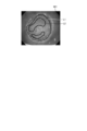
- FIG. 6 is a diagram showing how a second region is superimposed on a white light image. As shown in FIG. 6, a dashed line L1 indicating the first region and a solid line L2 indicating the second region may be superimposed on a white light image WI1. This makes it possible to grasp regions where hemostasis is insufficient while observing the white light image.
- the fluorescent image FI1 shown in FIG. 4 and the white light image shown in FIG. 6 may be displayed side-by-side so that they can be observed simultaneously.
- the control unit 405 may also have a function as a learning unit of the learning device that is the control device 4.
- the control unit 405 may generate a trained model by machine learning using teacher data in which a fluorescent image obtained by irradiating a living tissue with excitation light and capturing fluorescence is used as input data, and in which a second region identified based on position information of a second pixel having a luminance value equal to or less than a second threshold in a first region identified based on a first pixel having a luminance value equal to or more than a first threshold in the fluorescent image is superimposed on the fluorescent image as output data.
- the trained model is composed of a neural network in which each layer has one or more nodes.
- the type of machine learning is not particularly limited, but it is sufficient that, for example, teacher data and training data in which fluorescent images of multiple subjects are associated with an image in which a second region identified from the multiple fluorescent images is superimposed on the fluorescent image are prepared, and the teacher data and training data are input into a calculation model based on a multilayer neural network for training.
- a machine learning technique for example, a technique based on a deep neural network (DNN), which is a multilayer neural network such as a convolutional neural network (CNN) or a 3D-CNN, is used.
- DNN deep neural network
- CNN convolutional neural network
- 3D-CNN 3D-CNN
- a technique based on a recurrent neural network (RNN) or long short-term memory units (LSTM), which is an extension of an RNN may also be used.
- RNN recurrent neural network
- LSTM long short-term memory units
- a learning unit of a learning device different from the control device 4 may execute these functions.
Landscapes
- Engineering & Computer Science (AREA)
- Health & Medical Sciences (AREA)
- Life Sciences & Earth Sciences (AREA)
- Physics & Mathematics (AREA)
- Surgery (AREA)
- Medical Informatics (AREA)
- General Health & Medical Sciences (AREA)
- Animal Behavior & Ethology (AREA)
- Pathology (AREA)
- Biomedical Technology (AREA)
- Heart & Thoracic Surgery (AREA)
- Molecular Biology (AREA)
- Nuclear Medicine, Radiotherapy & Molecular Imaging (AREA)
- Biophysics (AREA)
- Public Health (AREA)
- Veterinary Medicine (AREA)
- Radiology & Medical Imaging (AREA)
- General Physics & Mathematics (AREA)
- Theoretical Computer Science (AREA)
- Optics & Photonics (AREA)
- Quality & Reliability (AREA)
- Computer Vision & Pattern Recognition (AREA)
- Software Systems (AREA)
- Multimedia (AREA)
- Signal Processing (AREA)
- Evolutionary Computation (AREA)
- Artificial Intelligence (AREA)
- Endoscopes (AREA)
Abstract
Priority Applications (3)
| Application Number | Priority Date | Filing Date | Title |
|---|---|---|---|
| PCT/JP2023/004406 WO2024166311A1 (fr) | 2023-02-09 | 2023-02-09 | Dispositif de traitement d'image, système médical, procédé de fonctionnement de dispositif de traitement d'image et dispositif d'apprentissage |
| CN202380093364.6A CN120641029A (zh) | 2023-02-09 | 2023-02-09 | 图像处理装置、医疗系统、图像处理装置的工作方法以及学习装置 |
| US19/290,895 US20250363634A1 (en) | 2023-02-09 | 2025-08-05 | Image processing device, medical system, method of operating image processing device, and training device |
Applications Claiming Priority (1)
| Application Number | Priority Date | Filing Date | Title |
|---|---|---|---|
| PCT/JP2023/004406 WO2024166311A1 (fr) | 2023-02-09 | 2023-02-09 | Dispositif de traitement d'image, système médical, procédé de fonctionnement de dispositif de traitement d'image et dispositif d'apprentissage |
Related Child Applications (1)
| Application Number | Title | Priority Date | Filing Date |
|---|---|---|---|
| US19/290,895 Continuation US20250363634A1 (en) | 2023-02-09 | 2025-08-05 | Image processing device, medical system, method of operating image processing device, and training device |
Publications (1)
| Publication Number | Publication Date |
|---|---|
| WO2024166311A1 true WO2024166311A1 (fr) | 2024-08-15 |
Family
ID=92262239
Family Applications (1)
| Application Number | Title | Priority Date | Filing Date |
|---|---|---|---|
| PCT/JP2023/004406 Ceased WO2024166311A1 (fr) | 2023-02-09 | 2023-02-09 | Dispositif de traitement d'image, système médical, procédé de fonctionnement de dispositif de traitement d'image et dispositif d'apprentissage |
Country Status (3)
| Country | Link |
|---|---|
| US (1) | US20250363634A1 (fr) |
| CN (1) | CN120641029A (fr) |
| WO (1) | WO2024166311A1 (fr) |
Citations (3)
| Publication number | Priority date | Publication date | Assignee | Title |
|---|---|---|---|---|
| WO2018061390A1 (fr) * | 2016-09-28 | 2018-04-05 | パナソニック株式会社 | Système d'affichage |
| WO2020012563A1 (fr) * | 2018-07-10 | 2020-01-16 | オリンパス株式会社 | Dispositif d'endoscope, dispositif de traitement et procédé de traitement |
| WO2020054723A1 (fr) * | 2018-09-10 | 2020-03-19 | オリンパス株式会社 | Dispositif d'observation d'agression thermique, système d'endoscope, système d'observation d'agression thermique et procédé d'observation d'agression thermique |
-
2023
- 2023-02-09 WO PCT/JP2023/004406 patent/WO2024166311A1/fr not_active Ceased
- 2023-02-09 CN CN202380093364.6A patent/CN120641029A/zh active Pending
-
2025
- 2025-08-05 US US19/290,895 patent/US20250363634A1/en active Pending
Patent Citations (3)
| Publication number | Priority date | Publication date | Assignee | Title |
|---|---|---|---|---|
| WO2018061390A1 (fr) * | 2016-09-28 | 2018-04-05 | パナソニック株式会社 | Système d'affichage |
| WO2020012563A1 (fr) * | 2018-07-10 | 2020-01-16 | オリンパス株式会社 | Dispositif d'endoscope, dispositif de traitement et procédé de traitement |
| WO2020054723A1 (fr) * | 2018-09-10 | 2020-03-19 | オリンパス株式会社 | Dispositif d'observation d'agression thermique, système d'endoscope, système d'observation d'agression thermique et procédé d'observation d'agression thermique |
Also Published As
| Publication number | Publication date |
|---|---|
| CN120641029A (zh) | 2025-09-12 |
| US20250363634A1 (en) | 2025-11-27 |
Similar Documents
| Publication | Publication Date | Title |
|---|---|---|
| US20230000330A1 (en) | Medical observation system, medical imaging device and imaging method | |
| US11045079B2 (en) | Endoscope device, image processing apparatus, image processing method, and program | |
| US20230248209A1 (en) | Assistant device, endoscopic system, assistant method, and computer-readable recording medium | |
| JP2011167349A (ja) | 画像処理装置及び画像処理方法 | |
| US12121219B2 (en) | Medical image processing device, medical imaging device, medical observation system, image processing method, and computer-readable recording medium | |
| WO2024166311A1 (fr) | Dispositif de traitement d'image, système médical, procédé de fonctionnement de dispositif de traitement d'image et dispositif d'apprentissage | |
| WO2024166304A1 (fr) | Dispositif de traitement d'image, système médical, procédé d'utilisation de dispositif de traitement d'image, et dispositif d'apprentissage | |
| US20250352032A1 (en) | Medical device, medical system, learning device, method of operating medical device, and computer-readable recording medium | |
| US20250359729A1 (en) | Medical device, medical system, learning device, operation method of medical device, and computer-readable recording medium | |
| US20250356490A1 (en) | Assistance device, operation method of assistance device, computer-readable recording medium, medical system, and learning device | |
| US20250352029A1 (en) | Medical device, medical system, operation method of medical device, and computer-readable recording medium | |
| US20250352028A1 (en) | Medical device, medical system, learning device, method of operating medical device, and computer-readable recording medium | |
| US20250359741A1 (en) | Medical device, medical system, medical device operation method, and computer-readable recording medium | |
| US20250352026A1 (en) | Medical device, medical system, operation method of medical device, and computer-readable recording medium | |
| US20250352071A1 (en) | Medical device, endoscope system, control method, and computer-readable recording medium | |
| US20250352049A1 (en) | Medical device, medical system, method of operating medical device, and computer-readable recording medium | |
| US20250359728A1 (en) | Control device, medical system, operation method of medical device, and computer-readable recording medium | |
| JP7642498B2 (ja) | 画像処理装置、画像処理方法、及びプログラム | |
| US20250359726A1 (en) | Medical apparatus, medical system, control method, and computer-readable recording medium | |
| WO2024166325A1 (fr) | Dispositif médical, système d'endoscope, procédé de commande, programme de commande et dispositif d'apprentissage | |
| WO2018225316A1 (fr) | Dispositif de commande médicale |
Legal Events
| Date | Code | Title | Description |
|---|---|---|---|
| 121 | Ep: the epo has been informed by wipo that ep was designated in this application |
Ref document number: 23921142 Country of ref document: EP Kind code of ref document: A1 |
|
| WWE | Wipo information: entry into national phase |
Ref document number: 202380093364.6 Country of ref document: CN |
|
| NENP | Non-entry into the national phase |
Ref country code: DE |
|
| WWP | Wipo information: published in national office |
Ref document number: 202380093364.6 Country of ref document: CN |
|
| 122 | Ep: pct application non-entry in european phase |
Ref document number: 23921142 Country of ref document: EP Kind code of ref document: A1 |