WO2024166323A1 - 無線基地局、無線中継装置、移動体、無線通信システム、無線通信方法、及びプログラム - Google Patents
無線基地局、無線中継装置、移動体、無線通信システム、無線通信方法、及びプログラム Download PDFInfo
- Publication number
- WO2024166323A1 WO2024166323A1 PCT/JP2023/004444 JP2023004444W WO2024166323A1 WO 2024166323 A1 WO2024166323 A1 WO 2024166323A1 JP 2023004444 W JP2023004444 W JP 2023004444W WO 2024166323 A1 WO2024166323 A1 WO 2024166323A1
- Authority
- WO
- WIPO (PCT)
- Prior art keywords
- wireless relay
- relay device
- communication
- wireless
- load
- Prior art date
- Legal status (The legal status is an assumption and is not a legal conclusion. Google has not performed a legal analysis and makes no representation as to the accuracy of the status listed.)
- Ceased
Links
Images


Classifications
-
- H—ELECTRICITY
- H04—ELECTRIC COMMUNICATION TECHNIQUE
- H04W—WIRELESS COMMUNICATION NETWORKS
- H04W28/00—Network traffic management; Network resource management
- H04W28/02—Traffic management, e.g. flow control or congestion control
- H04W28/08—Load balancing or load distribution
- H04W28/09—Management thereof
- H04W28/0925—Management thereof using policies
-
- H—ELECTRICITY
- H04—ELECTRIC COMMUNICATION TECHNIQUE
- H04W—WIRELESS COMMUNICATION NETWORKS
- H04W16/00—Network planning, e.g. coverage or traffic planning tools; Network deployment, e.g. resource partitioning or cells structures
- H04W16/24—Cell structures
- H04W16/26—Cell enhancers or enhancement, e.g. for tunnels, building shadow
-
- H—ELECTRICITY
- H04—ELECTRIC COMMUNICATION TECHNIQUE
- H04W—WIRELESS COMMUNICATION NETWORKS
- H04W28/00—Network traffic management; Network resource management
- H04W28/02—Traffic management, e.g. flow control or congestion control
- H04W28/08—Load balancing or load distribution
- H04W28/0858—Load balancing or load distribution among entities in the uplink
-
- H—ELECTRICITY
- H04—ELECTRIC COMMUNICATION TECHNIQUE
- H04W—WIRELESS COMMUNICATION NETWORKS
- H04W36/00—Hand-off or reselection arrangements
- H04W36/16—Performing reselection for specific purposes
- H04W36/22—Performing reselection for specific purposes for handling the traffic
-
- H—ELECTRICITY
- H04—ELECTRIC COMMUNICATION TECHNIQUE
- H04W—WIRELESS COMMUNICATION NETWORKS
- H04W36/00—Hand-off or reselection arrangements
- H04W36/24—Reselection being triggered by specific parameters
- H04W36/32—Reselection being triggered by specific parameters by location or mobility data, e.g. speed data
-
- H—ELECTRICITY
- H04—ELECTRIC COMMUNICATION TECHNIQUE
- H04W—WIRELESS COMMUNICATION NETWORKS
- H04W84/00—Network topologies
-
- H—ELECTRICITY
- H04—ELECTRIC COMMUNICATION TECHNIQUE
- H04W—WIRELESS COMMUNICATION NETWORKS
- H04W92/00—Interfaces specially adapted for wireless communication networks
- H04W92/16—Interfaces between hierarchically similar devices
- H04W92/20—Interfaces between hierarchically similar devices between access points
Definitions
- the present invention relates to a wireless base station, a wireless relay device, a mobile object, a wireless communication system, a wireless communication method, and a program.
- Patent Documents 1 to 5 describe techniques relating to mobile communications.
- Patent Document 1 JP 2004-221680
- Patent Document 2 Japanese Patent No. 6013984
- Patent Document 3 Japanese Patent No. 5440117
- Patent Document 4 Japanese Patent No. 5321319
- Patent Document 5 Japanese Patent No. 6239572 A
- mobile communications provided by mobile objects have a problem of being prone to overload due to limited communication capacity.
- the present application can improve the stability of communications in mobile objects. This, in turn, can further improve traffic safety and contribute to the development of a sustainable transportation system.
- a wireless relay device relays communication between a terminal device and a base station.
- the wireless relay device performs wireless communication with one or more terminal devices, and includes a communication unit that transmits load information indicating the communication load of the wireless relay device to another wireless relay device and receives load information indicating the communication load of the other wireless relay device.
- the wireless relay device includes a control unit that performs control to switch the communication connection destination of some terminal devices, among a plurality of terminal devices that are communicatively connected to the wireless relay device, to the other wireless relay device based on the communication load of the wireless relay device and the communication load of the other wireless relay device.
- control unit may perform control to switch the communication connection destination of some of the multiple terminal devices to the other wireless relay device when the communication load of the wireless relay device exceeds a predetermined value and the communication load of the other wireless relay device is less than a predetermined value.
- control unit may determine the number of terminal devices among the multiple terminal devices that should switch their communication connection destination to the other wireless relay device based on the communication load of the wireless relay device and the communication load of the other wireless relay device.
- the communication unit may receive information indicating the location of the other wireless relay device.
- the control unit may perform control to switch the communication connection destination of some of the multiple terminal devices to the other wireless relay device based on the communication load of the wireless relay device, the communication load of the other wireless relay device, the location of the wireless relay device, and the location of the other wireless relay device.
- the communication unit may receive information indicating a history of the past locations of the other wireless relay devices.
- the control unit may perform control to switch the communication connection destination of some of the multiple terminal devices to the other wireless relay devices based on the communication load of the wireless relay device, the communication load of the other wireless relay devices, the history of the past locations of the wireless relay device, and the history of the locations of the other wireless relay devices.
- a mobile object is provided.
- the mobile object is equipped with any of the wireless relay devices described above.
- a program in a third aspect, causes a computer to function as any one of the wireless relay devices described above.
- a wireless base station communicates with a terminal device via a wireless relay device.
- the wireless base station includes a communication unit that receives load information indicating a first communication load in a first wireless relay device and load information indicating a second communication load in a second wireless relay device.
- the wireless base station includes a control unit that performs control to switch the communication connection destination of some of the multiple terminal devices that are communication-connected to the first wireless relay device to the second wireless relay device based on the first communication load and the second communication load.
- the communication unit may further receive first quality information from the first wireless relay device, which indicates the quality of radio waves of the second wireless relay device measured at the first wireless relay device, and may also receive second quality information from the second wireless relay device, which indicates the quality of radio waves of the first wireless relay device measured at the second wireless relay device.
- the control unit may perform control to switch the communication connection destination of some of the multiple terminal devices connected to the first wireless relay device to the second wireless relay device, based on the first quality information and the second quality information.
- the communication unit may further receive first location information indicating the location of the first wireless relay device and second location information indicating the location of the second wireless relay device.
- the control unit may perform control to switch the communication connection destination of some of the multiple terminal devices connected to the first wireless relay device to the second wireless relay device based on the first location information and the second location information.
- the communication unit may further receive first location history information indicating a history of a past location of the first wireless relay device and second location history information indicating a history of a past location of the second wireless relay device.
- the control unit may perform control to switch the communication connection destination of some of the multiple terminal devices connected to the first wireless relay device to the second wireless relay device based on the first location history information and the second location history information.
- a wireless communication system includes any one of the wireless base stations described above, the first wireless relay device, and the second wireless relay device.
- a program causes a computer to function as any one of the wireless base stations described above.
- a wireless communication method is provided.
- the wireless communication method is executed by a wireless relay device that relays communication between a terminal device and a base station.
- the wireless communication method includes a step of performing wireless communication with one or more terminal devices, transmitting load information indicating the communication load of the wireless relay device to another wireless relay device, and receiving load information indicating the communication load of the other wireless relay device.
- the wireless communication method includes a step of performing control to switch the communication connection destination of some terminal devices, among a plurality of terminal devices that are communicatively connected to the wireless relay device, to the other wireless relay device, based on the communication load of the wireless relay device and the communication load of the other wireless relay device.
- a wireless communication method is provided.
- the wireless communication method is executed by a wireless base station that communicates with a terminal device via a wireless relay device.
- the wireless communication method includes a step of receiving load information indicating a first communication load in a first wireless relay device and load information indicating a second communication load in a second wireless relay device.
- the wireless communication method includes a step of performing control to switch the communication connection destination of some terminal devices among a plurality of terminal devices that are communication-connected to the first wireless relay device to the second wireless relay device based on the first communication load and the second communication load.
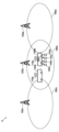
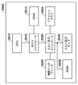
- 1 illustrates a schematic configuration of a wireless communication system 5 according to an embodiment.
- 2 shows an example of a system configuration of a wireless relay device 110.
- 2 shows an example of a system configuration of a wireless base station 120.
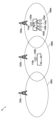
- 1 shows the connection state of the terminal equipment 140 when the mobile unit 100a is located in a cell 180a and the mobile unit 100b is located in a cell 180b.
- 13 shows a state in which the communication connection destination of the two terminal devices 140 is switched to the wireless relay device 110b as a result of the moving object 100a approaching the moving object 100b.
- the connection state of the terminal equipment 140 is shown when the mobile unit 100a moves further and is located within a cell 180c of a wireless base station 120c.
- 1 shows an example of a sequence relating to a wireless communication method executed in the wireless communication system 5.
- 1 shows an example of a sequence relating to a wireless communication method executed in the wireless communication system 5.
- 2 illustrates an example computer 2000 upon which embodiments of the present invention may be implemented in whole or in part.
- FIG. 1 shows a schematic configuration of a wireless communication system 5 according to one embodiment.
- the wireless communication system 5 includes wireless base stations 120a, 120b, and 120c, wireless relay devices 110a and 110b, mobile units 100a and 100b, and terminal devices 140a, 140b, 140c, and 140d.
- the wireless base stations 120a, 120b, and 120c may be collectively referred to as "wireless base stations 120" with the suffixes of their reference symbols omitted.
- the wireless relay devices 110a and 110b may be collectively referred to as “wireless relay devices 110” with the suffixes of their reference symbols omitted.
- the mobile units 100a and 100b may be collectively referred to as “mobile units 100” with the suffixes of their reference symbols omitted.
- the terminal devices 140a, 140b, 140c, and 140d may be collectively referred to as "terminal devices 140" with the suffixes of their reference symbols omitted.
- the wireless base station 120 is a mobile communication base station that supports one or more mobile communication methods.
- the wireless relay device 110 and the terminal device 140 are wireless communication devices that support one or more mobile communication methods.
- the mobile communication methods supported by the wireless base station 120, the wireless relay device 110, and the terminal device 140 may be, for example, mobile communication methods used in mobile communication systems such as the fourth generation mobile communication system (4G) and the fifth generation mobile communication system (5G).
- the wireless base stations 120 are base stations fixed to specific locations. Each of the wireless base stations 120 forms a cell, and by forming the cell, performs wireless communication with the wireless relay device 110 and the terminal device 140.
- cell 180a is a cell formed by wireless base station 120a
- cell 180b is a cell formed by wireless base station 120b
- cell 180c is a cell formed by wireless base station 120c.
- cell 180a, cell 180b, and cell 180c may be collectively referred to as "cell 180" with the suffixes of the reference numbers omitted.
- the wireless relay device 110 has a function for providing services to the terminal device 140 as a wireless base station, and also has a function for receiving services from the wireless base station 120 as a terminal device.
- the wireless relay device 110 relays communications between the terminal device 140 and the wireless base station 120.
- the terminal device 140 can access the core network via the wireless base station 120. Even if the terminal device 140 cannot directly communicate wirelessly with the wireless base station 120, it may be possible for the terminal device 140 to access the core network via the wireless relay device 110 and the wireless base station 120.
- the mobile body 100 is a mobile device.
- the mobile body 100 is, for example, a vehicle such as a bus or an automobile, or a train.
- a vehicle is an example of a transportation device.
- the mobile body 100 may be various types of aircraft including unmanned aerial vehicles, an artificial satellite, a ship, etc.
- the mobile body 100a is equipped with a wireless relay device 110a.
- the mobile body 100b is equipped with a wireless relay device 110b. Therefore, the wireless relay device 110a can move together with the mobile body 100a, and the wireless relay device 110b can move together with the mobile body 100b.
- the wireless relay device 110a relays communications between the wireless base station 120b and each of the terminal devices 140a, 140b, 140c, and 140d carried by the user on the mobile unit 100a.
- the terminal device 140 carried by the user of the wireless relay device 110a is in a position where it can communicate wirelessly with the wireless relay device 110b, and therefore it is possible to switch the communication connection destination of the terminal device 140 to the wireless relay device 110b.
- the wireless relay device 110a, the wireless relay device 110b, and the wireless base station 120b cooperate to switch the communication connection destination of two of the four terminal devices 140, the terminal device 140a and the terminal device 140b, which are communicatively connected to the wireless relay device 110a, to the wireless relay device 110b.
- the wireless relay device 110a and the wireless relay device 110b exchange their communication loads with each other, and the wireless relay device 110a decides to switch the communication connection destination of the terminal device 140a and the terminal device 140b to the wireless relay device 110b based on the communication loads of the other devices.
- the wireless relay device 110a and the wireless relay device 110b transmit their respective communication loads to the wireless base station 120, and the wireless base station 120b decides to switch the communication connection destination of the terminal device 140a and the terminal device 140b to the wireless relay device 110b. This allows load distribution among multiple wireless relay devices 110.
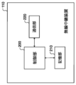
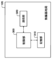
- FIG. 2 shows an example of the system configuration of the wireless relay device 110.
- the wireless relay device 110 relays communications between the wireless base station 120 and the terminal device 140.
- the wireless relay device 110 includes a control unit 200, a storage unit 210, and a communication unit 220.
- the control unit 200 controls the entire wireless relay device 110.
- the communication unit 220 is responsible for wireless communication between the wireless base station 120 and the terminal device 140.
- the control unit 200 is realized by an arithmetic processing device including a processor.
- the storage unit 210 is realized by including a non-volatile storage medium.
- the control unit 200 performs processing using information stored in the storage unit 210.
- the control unit 200 may be realized by a microcomputer including a CPU, ROM, RAM, I/O, a bus, etc.
- the wireless relay device 110 may be realized by a computer.
- the wireless relay device 110 may be realized by a single computer.
- the wireless relay device 110 may be realized by multiple computers.
- the functions of the wireless relay device 110 may be realized by a virtual system realized using virtualization technology.
- the communication unit 220 performs wireless communication with one or more terminal devices 140.
- the communication unit 220 transmits load information indicating the communication load of the wireless relay device 110 to the other wireless relay devices 110, and receives load information indicating the communication load of the other wireless relay devices 110.
- the control unit 200 performs control to switch the communication connection destination of some of the multiple terminal devices 140 that are communication-connected to the wireless relay device 110 to the other wireless relay devices 110, based on the communication load of the wireless relay device 110 and the communication load of the other wireless relay devices 110.
- the control unit 200 may perform control to switch the communication connection destination of some of the multiple terminal devices 140 to other wireless relay devices 110 when the communication load of the wireless relay device 110 exceeds a predetermined value and the communication load of the other wireless relay devices 110 is less than a predetermined value.
- the control unit 200 may determine the number of terminal devices 140 that should switch their communication connection destination to other wireless relay devices 110, among the multiple terminal devices 140, based on the communication load of the wireless relay device 110 and the communication load of other wireless relay devices 110.
- the communication unit 220 receives information indicating the positions of the other wireless relay devices 110.
- the control unit 200 performs control to switch the communication connection destination of some of the multiple terminal devices 140 to the other wireless relay devices 110 based on the communication load of the wireless relay device 110, the communication load of the other wireless relay devices 110, the position of the wireless relay device 110, and the positions of the other wireless relay devices 110.
- the "information indicating the position of the wireless relay device 110" may be information indicating the current position of the wireless relay device 110.
- the information indicating the current position of the wireless relay device 110 may be information indicating the geographical position of the wireless relay device 110, for example, the latitude and longitude of the wireless relay device 110.
- the communication unit 220 may receive information indicating the past location history of the other wireless relay devices 110.
- the control unit 200 may perform control to switch the communication connection destination of some of the multiple terminal devices 140 to the other wireless relay devices 110 based on the communication load of the wireless relay device 110, the communication load of the other wireless relay devices 110, the past location history of the wireless relay device 110, and the location history of the other wireless relay devices 110.
- FIG. 3 shows an example of the system configuration of the wireless base station 120.
- the wireless base station 120 communicates with the terminal device 140 via the wireless relay device 110.
- the wireless base station 120 includes a control unit 300, a storage unit 310, and a communication unit 320.
- the control unit 300 controls the entire wireless base station 120.
- the communication unit 320 is responsible for wireless communication between the wireless relay device 110 and the terminal device 140.
- the control unit 300 is realized by an arithmetic processing device including a processor.
- the storage unit 310 is realized by including a non-volatile storage medium.
- the control unit 300 performs processing using information stored in the storage unit 310.
- the control unit 300 may be realized by a microcomputer including a CPU, ROM, RAM, I/O, a bus, etc.
- the wireless base station 120 may be realized by a computer.
- the wireless base station 120 may be realized by a single computer.
- the wireless base station 120 may be realized by multiple computers.
- the functions of the wireless base station 120 may be realized by a virtual system realized using virtualization technology.
- the communication unit 320 receives load information indicating a first communication load in the first wireless relay device 110 and second load information indicating a second communication load in the second wireless relay device 110.
- the control unit 300 performs control to switch the communication connection destination of some of the multiple terminal devices 140 that are communicatively connected to the first wireless relay device 110 to the second wireless relay device 110 based on the first communication load and the second communication load.
- the communication unit 320 may further receive from the first wireless relay device 110 first quality information indicating the quality of radio waves of the second wireless relay device 110 measured at the first wireless relay device 110, and may also receive from the second wireless relay device 110 second quality information indicating the quality of radio waves of the first wireless relay device 110 measured at the second wireless relay device 110.
- the control unit 300 may perform control to switch the communication connection destination of some of the multiple terminal devices 140 connected to the first wireless relay device 110 to the second wireless relay device 110 based on the first quality information and the second quality information.
- the communication unit 320 may further receive first location information indicating the location of the first wireless relay device 110 and second location information indicating the location of the second wireless relay device 110.
- the control unit 300 may perform control to switch the communication connection destination of some of the multiple terminal devices 140 connected to the first wireless relay device 110 to the second wireless relay device 110 based on the first location information and the second location information.
- the "information indicating the location of the wireless relay device 110" may be information indicating the current location of the wireless relay device 110.
- the information indicating the current location of the wireless relay device 110 may be information indicating the geographical location of the wireless relay device 110, for example, the latitude and longitude of the wireless relay device 110.
- the communication unit 320 may further receive first location history information indicating the past location history of the first wireless relay device 110 and second location history information indicating the past location history of the second wireless relay device 110.
- the control unit 300 may perform control to switch the communication connection destination of some of the multiple terminal devices 140 connected to the first wireless relay device 110 to the second wireless relay device 110 based on the first location history information and the second location history information.
- Figure 4 shows the connection state of the terminal devices 140 when the mobile unit 100a is located in cell 180a and the mobile unit 100b is located in cell 180b. All of the terminal devices 140 in the mobile unit 100a are communicatively connected to the wireless relay device 110a, and are connected to the core network through the wireless relay device 110a and the wireless base station 120a. In the situation in Figure 4, the terminal device 140 is located away from the wireless relay device 110b, so the communication connection destination of the terminal device 140 cannot be switched to the wireless relay device 110b. Therefore, load balancing is not performed by the wireless relay devices 110a and 110b.
- FIG. 5 shows a state in which the communication connection destination of two terminal devices 140 is switched to wireless relay device 110b as a result of moving body 100a approaching moving body 100b.
- the communication connection destination of terminal device 140a and terminal device 140b out of the four terminal devices 140 that were communicatively connected to wireless relay device 110a is switched to wireless relay device 110b.
- Terminal device 140a and terminal device 140b are connected to the core network via wireless relay device 110b, and terminal device 140c and terminal device 140d are connected to the core network via wireless relay device 110a. This allows load balancing by wireless relay device 110a and wireless relay device 110b.
- Figure 6 shows the connection state of terminal device 140 when mobile unit 100a moves further and is located within cell 180c of wireless base station 120c. As mobile unit 100a moves away from mobile unit 100b, the quality of communication between terminal device 140 and wireless relay device 110b decreases. In response, terminal device 140a and terminal device 140b, which were connected to wireless relay device 110b, switch to wireless relay device 110a as their connection destination. This makes it possible to prevent communication between terminal device 140 and the outside world from being interrupted.
- FIG. 7 shows an example of a sequence relating to a wireless communication method executed in the wireless communication system 5.
- FIG. 7 shows a sequence of a method in which the wireless relay device 110 mainly plays a role in switching the communication connection destination of the terminal device 140.
- the main processing executed from the connection state of FIG. 4 to the connection state of FIG. 6 will be explained along with the sequence of FIG. 7.
- the terminal device 140a and communication terminal 140b that are the switching targets only the terminal device 140a is shown in FIG. 7, but the processing of the terminal device 140b is similar to that of the terminal device 140a.
- the terminal device 140a is connected to the wireless relay device 110a and is in communication (S11), and the terminal device 140a is connected to the wireless base station 120 and the core network through the wireless relay device 110a.
- the wireless relay device 110a and the wireless relay device 110b exchange load information indicating each other's communication load.
- the control units 200 of the wireless relay device 110a and the wireless relay device 110b determine whether or not the connection destination of some of the terminal devices 140 connected to the wireless relay device 110a can be switched to the wireless relay device 110b according to predetermined conditions.
- control unit 200 may determine that some of the connections of the terminal device 140 can be switched to the wireless relay device 110b when the difference between the communication load rate of the wireless relay device 110a and the communication load rate of the wireless relay device 110b is greater than a predetermined value.
- the control unit 200 may determine that some of the connections of the terminal device 140 can be switched to the wireless relay device 110b when the communication load rate of the wireless relay device 110a is higher than a predetermined first threshold value and the communication load rate of the wireless relay device 110b is lower than a second threshold value that is lower than the first threshold value.
- the control unit 200 may further determine the number N of terminal devices 140 whose connection should be switched to the wireless relay device 110b based on the communication load rate of the wireless relay device 110a and the communication load rate of the wireless relay device 110b.
- the control unit 200 may increase N as the difference between the communication load rate of the wireless relay device 110a and the communication load rate of the wireless relay device 110b increases. In this embodiment, it is assumed that it has been determined that the connection of the terminal devices 140a and 140b should be switched to the wireless relay device 110b.
- the wireless relay device 110a transmits a surrounding base station measurement control command to the terminal device 140 (S13).
- the terminal device 140 receives the surrounding base station measurement control command, it acquires the reception status of signals such as notification information transmitted from the surrounding base stations.
- the terminal device 140 may acquire the RSRP and RSRQ of the signals transmitted from the surrounding base stations.
- the terminal device 140 transmits the measurement result indicating the radio wave reception state to the wireless relay device 110a (S14).
- the control unit 200 of the wireless relay device 110a determines based on the received measurement result that the communication connection destination of the terminal device 140 can be switched to the wireless relay device 110b
- the communication unit 220 of the wireless relay device 110a transmits a switch request to the wireless relay device 110b (S15) and transmits a switch instruction to the terminal devices 140a and 140b to switch the communication connection destination (S16).
- the communication unit 220 of the wireless relay device 110a transfers the unsent data to the wireless relay device 110b together with the identification information of the terminal devices 140a and 140b to be switched (S17).
- the control unit 200 of the wireless relay device 110b performs line synchronization processing between the terminal device 140a and the terminal device 140b (S18) and transmits a path switching request to the core network (S19).
- the communication unit 220 of the wireless relay device 110b transmits a switching completion notification to the core network (S21).
- the communication connection destination of the terminal device 140a and the terminal device 140b is switched to the wireless relay device 110b, and communication between the terminal device 140a and the wireless relay device 110b and the terminal device 140b is started (S22).
- the terminal device 140a and the terminal device 140b are connected to the wireless relay device 110b as shown in FIG. 5.
- the wireless relay device 110b transmits a surrounding base station measurement control command to the terminal device 140a and the terminal device 140b.
- the wireless relay device 110b may transmit the surrounding base station measurement control command periodically.
- the terminal device 140a and the terminal device 140b measure the reception state of signals such as notification information transmitted from the surrounding base stations. For example, the terminal device 140a and the terminal device 140b may calculate the RSRP and RSRQ of the signals transmitted from the surrounding base stations.
- the terminal device 140 transmits the measurement result indicating the radio wave reception state to the wireless relay device 110b (S31).
- the control unit 200 of the wireless relay device 110b determines based on the measurement result that the communication connection destination of the terminal device 140 should be switched to the wireless relay device 110a
- the communication unit 220 of the wireless relay device 110b transmits a switch request to the wireless relay device 110a (S32) and transmits a switch instruction to the terminal devices 140a and 140b to switch the communication connection destination (S33).
- the communication unit 220 of the wireless relay device 110b transfers the unsent data to the wireless relay device 110a together with the identification information of the terminal devices 140a and 140b to be switched (S34).
- the control unit 200 of the wireless relay device 110a synchronizes the lines with the terminal devices 140a and 140b (S35) and transmits a path switching request to the core network (S36).
- the communication unit 220 of the wireless relay device 110a transmits a switching completion notification to the core network (S38). This switches the communication connection destination of the terminal devices 140a and 140b to the wireless relay device 110a, and communication between the terminal devices 140a and 140b and the wireless relay device 110a is resumed (S39).
- the wireless relay device 110a may further take into consideration the current location of the wireless relay device 110a and the current location information of the wireless relay device 110b. For example, the distance between the current location of the wireless relay device 110a and the current location of the wireless relay device 110b being less than a predetermined length may be used as a necessary condition to determine whether or not the connection destination of a portion of the terminal device 140 can be switched to another wireless relay device 110b.
- the wireless relay device 110a may further take into consideration the past location history of each of the wireless relay devices 110a and 110b. For example, a necessary condition may be that the degree of agreement between the moving direction of the wireless relay device 110a and the moving direction of the wireless relay device 110b calculated from the position history of the wireless relay device 110a and the position history of the wireless relay device 110b is higher than a predetermined value, and it may be determined whether the connection destination of a part of the terminal device 140 can be switched to another wireless relay device 110b.
- the position information of the wireless relay device 110a and the wireless relay device 110b may be exchanged with each other in S12.
- FIG. 8 shows an example of a sequence related to a wireless communication method executed in the wireless communication system 5.
- FIG. 8 shows a sequence of a method in which the wireless base station 120 mainly plays a role in switching the communication connection destination of the terminal device 140.
- the main processing executed from the connection state of FIG. 4 to the connection state of FIG. 6 will be explained along the sequence of FIG. 8.
- the terminal devices 140a and 140b to be switched only the terminal device 140a is shown in FIG. 8, but the processing of the terminal device 140b is the same as that of the terminal device 140a.
- the terminal device 140a is connected to the wireless relay device 110a and is in communication (S51), and the terminal device 140a is connected to the wireless base station 120 and the core network through the wireless relay device 110a.
- the wireless relay device 110a transmits load information indicating the communication load in the wireless relay device 110a and radio wave information from the surrounding base stations to the wireless base station 120 (S52), and the wireless relay device 110b transmits load information indicating the communication load in the wireless relay device 110b and radio wave information from the wireless relay device 110b to the wireless base station 120 (S53).
- the control unit 300 of the wireless base station 120 determines which of the terminal devices 140 connected to the wireless relay device 110a should be switched to the wireless relay device 110b.
- the radio wave information from the wireless relay device 110b may be information indicating the strength and/or quality of the radio waves transmitted from the wireless relay device 110b and received by the wireless relay device 110a.
- the radio wave information from the wireless relay device 110a may be information indicating the strength and/or quality of the radio waves transmitted from the wireless relay device 110a and received by the wireless relay device 110b.
- the radio information may include, for example, RSRP and RSRQ.
- control unit 300 may determine that some of the connections of the terminal device 140 can be switched to the wireless relay device 110b when the difference between the communication load rate of the wireless relay device 110a and the communication load rate of the wireless relay device 110b is greater than a predetermined value.
- the control unit 300 may determine that some of the connections of the terminal device 140 can be switched to the wireless relay device 110b when the communication load rate of the wireless relay device 110a is higher than a predetermined first threshold value and the communication load rate of the wireless relay device 110b is lower than a second threshold value that is lower than the first threshold value.
- control unit 300 may determine that the connection destination of some of the terminal devices 140 can be switched to the wireless relay device 110b under the condition that at least the strength and/or quality of the radio waves from the wireless relay device 110b measured at the wireless relay device 110a is higher than a predetermined reference value, and the strength and/or quality of the radio waves from the wireless relay device 110a measured at the wireless relay device 110b is higher than a predetermined reference value.
- the control unit 300 may further determine the number N of terminal devices 140 whose connection should be switched to wireless relay device 110b based on the communication load rate of wireless relay device 110a and the communication load rate of wireless relay device 110b.
- the control unit 300 may increase N as the difference between the communication load rate of wireless relay device 110a and the communication load rate of wireless relay device 110b increases. In this embodiment, it is assumed that it has been determined that the communication connection destination of terminal device 140a and terminal device 140b should be switched to wireless relay device 110b.
- the communication unit 320 of the wireless base station 120 transmits a switch request to the wireless relay device 110b to which the communication connection is to be switched (S55), and transmits a switch instruction to switch the communication connection destination to the terminal devices 140a and 140b and the wireless relay device 110a (S56).
- the communication unit 220 of the wireless relay device 110a receives the switch instruction, it transfers the unsent data to the wireless relay device 110b together with the identification information of the terminal devices 140a and 140b to which the communication connection destination is to be switched (S57).
- the control unit 200 of the wireless relay device 110b performs line synchronization processing between the terminal device 140a and the terminal device 140b (S58) and transmits a path switching request to the core network (S59).
- the communication unit 220 of the wireless relay device 110b transmits a switching completion notification to the core network (S61).
- the communication connection destination of the terminal device 140a and the terminal device 140b is switched to the wireless relay device 110b, and communication between the terminal device 140a and the wireless relay device 110b and the terminal device 140b is started (S62).
- the terminal device 140a and the terminal device 140b are connected to the wireless relay device 110b as shown in FIG. 5.
- the wireless base station 120 may further take into consideration the current location of the wireless relay device 110a and the current location information of the wireless relay device 110b. For example, the distance between the current location of the wireless relay device 110a and the current location of the wireless relay device 110b being less than a predetermined length may be used as a necessary condition to determine whether or not the connection destination of a portion of the terminal device 140 can be switched to another wireless relay device 110b.
- the wireless base station 120 may further take into consideration the past location history of each of the wireless relay devices 110a and 110b. For example, a necessary condition may be that the degree of agreement between the moving direction of the wireless relay device 110a and the moving direction of the wireless relay device 110b calculated from the position history of the wireless relay device 110a and the position history of the wireless relay device 110b is higher than a predetermined value, and it may be determined whether or not the connection destination of a part of the terminal device 140 can be switched to another wireless relay device 110b.
- the position information of the wireless relay device 110a and the wireless relay device 110b may be transmitted to the wireless base station 120 in S52 and S53.
- the communication connection destination of the terminal device 140a and the terminal device 140b can be switched to the wireless relay device 110b based on the communication load in the wireless relay device 110a. This makes it possible to distribute the load among the multiple wireless relay devices 110. This makes it possible to improve the stability of communication by the wireless relay device 110, and ultimately to increase the traffic safety of the mobile object 100.
- FIG. 9 shows an example of a computer 2000 in which multiple embodiments of the present invention may be embodied in whole or in part.
- a program installed on the computer 2000 may cause the computer 2000 to function as a system or each part of a system according to an embodiment, or various devices such as a wireless base station and a wireless relay device, or each part of the devices, perform operations associated with the system or each part of the system or the devices or each part of the devices, and/or perform a process or steps of the process according to an embodiment.
- Such a program may be executed by the CPU 2012 to cause the computer 2000 to perform specific operations associated with some or all of the blocks of the processing procedures and block diagrams described in this specification.
- the computer 2000 includes a CPU 2012 and a RAM 2014, which are interconnected by a host controller 2010.
- the computer 2000 also includes a ROM 2026, a flash memory 2024, a communication interface 2022, and an input/output chip 2040.
- the ROM 2026, the flash memory 2024, the communication interface 2022, and the input/output chip 2040 are connected to the host controller 2010 via the input/output controller 2020.
- the CPU 2012 operates according to the programs stored in the ROM 2026 and RAM 2014, thereby controlling each unit.
- the communication interface 2022 communicates with other electronic devices via a network.
- the flash memory 2024 stores programs and data used by the CPU 2012 in the computer 2000.
- the ROM 2026 stores programs such as a boot program executed by the computer 2000 upon activation, and/or programs that depend on the hardware of the computer 2000.
- the input/output chip 2040 may also connect various input/output units such as a keyboard, mouse, and monitor to the input/output controller 2020 via input/output ports such as a serial port, a parallel port, a keyboard port, a mouse port, a monitor port, a USB port, an HDMI port, etc.
- the programs are provided via a computer-readable storage medium such as a CD-ROM, DVD-ROM, or memory card, or via a network.
- RAM 2014, ROM 2026, or flash memory 2024 are examples of computer-readable storage media.
- the programs are installed in flash memory 2024, RAM 2014, or ROM 2026, and executed by CPU 2012. Information processing described in these programs is read by computer 2000, and brings about cooperation between the programs and the various types of hardware resources described above.
- An apparatus or method may be constructed by realizing the operation or processing of information according to the use of computer 2000.
- CPU 2012 may execute a communication program loaded into RAM 2014 and instruct communication interface 2022 to perform communication processing based on the processing described in the communication program.
- communication interface 2022 reads transmission data stored in a transmission buffer processing area provided in a recording medium such as RAM 2014 or flash memory 2024, transmits the read transmission data to the network, and writes received data received from the network to a reception buffer processing area or the like provided on the recording medium.
- the CPU 2012 may also cause all or a necessary portion of a file or database stored in a recording medium such as a flash memory 2024 to be read into the RAM 2014, and perform various types of processing on the data in the RAM 2014. The CPU 2012 then writes the processed data back to the recording medium.
- a recording medium such as a flash memory 2024
- Various types of information such as various types of programs, data, tables, and databases, may be stored on the recording medium and subjected to information processing.
- the CPU 2012 may execute various types of processing on the data read from the RAM 2014, including various types of operations, information processing, conditional judgment, conditional branching, unconditional branching, information search/replacement, etc., as described herein and specified by the instruction sequence of the program, and write the results back to the RAM 2014.
- the CPU 2012 may also search for information in a file, database, etc. in the recording medium.
- the CPU 2012 may search for an entry that matches a condition, in which an attribute value of the first attribute is specified, from among the multiple entries, read the attribute value of the second attribute stored in the entry, and thereby obtain the attribute value of the second attribute associated with the first attribute that satisfies a predetermined condition.
- the above-described programs or software modules may be stored in a computer-readable storage medium on the computer 2000 or in the vicinity of the computer 2000.
- a recording medium such as a hard disk or RAM provided in a server system connected to a dedicated communication network or the Internet can be used as the computer-readable storage medium.
- the programs stored in the computer-readable storage medium may be provided to the computer 2000 via the network.
- a program installed in computer 2000 that causes computer 2000 to function as wireless relay device 110 may act on CPU 2012, etc., to cause computer 2000 to function as each part of wireless relay device 110.
- the information processing described in these programs is loaded into computer 2000, it functions as each part of wireless relay device 110, which is a concrete means in which software and the various hardware resources described above work together. These concrete means then realize calculations or processing of information according to the intended use of computer 2000 in this embodiment, thereby constructing a unique wireless relay device 110 according to the intended use.
- a program installed in computer 2000 that causes computer 2000 to function as wireless base station 120 may act on CPU 2012 and the like to cause computer 2000 to function as each part of wireless base station 120.
- the information processing described in these programs is loaded into computer 2000, it functions as each part of wireless base station 120, which is a concrete means in which software and the various hardware resources described above work together. These concrete means then realize calculations or processing of information according to the intended use of computer 2000 in this embodiment, thereby constructing a unique wireless base station 120 according to the intended use.
- each block may represent (1) a stage of a process where an operation is performed or (2) a portion of an apparatus responsible for performing an operation.
- Particular stages and portions may be implemented by dedicated circuitry, programmable circuitry provided with computer-readable instructions stored on a computer-readable storage medium, and/or a processor provided with computer-readable instructions stored on a computer-readable storage medium.
- Dedicated circuitry may include digital and/or analog hardware circuitry, and may include integrated circuits (ICs) and/or discrete circuits.
- Programmable circuitry may include reconfigurable hardware circuitry, including logic AND, logic OR, logic XOR, logic NAND, logic NOR, and other logic operations, memory elements such as flip-flops, registers, field programmable gate arrays (FPGAs), programmable logic arrays (PLAs), and the like.
- reconfigurable hardware circuitry including logic AND, logic OR, logic XOR, logic NAND, logic NOR, and other logic operations, memory elements such as flip-flops, registers, field programmable gate arrays (FPGAs), programmable logic arrays (PLAs), and the like.
- a computer-readable storage medium may include any tangible device capable of storing instructions that are executed by a suitable device, such that the computer-readable storage medium having instructions stored thereon constitutes at least a portion of a product that includes instructions that can be executed to provide a means for performing the operations specified in a process or block diagram.
- Examples of computer-readable storage media may include electronic storage media, magnetic storage media, optical storage media, electromagnetic storage media, semiconductor storage media, and the like.
- Computer-readable storage media may include floppy disks, diskettes, hard disks, random access memories (RAMs), read-only memories (ROMs), erasable programmable read-only memories (EPROMs or flash memories), electrically erasable programmable read-only memories (EEPROMs), static random access memories (SRAMs), compact disk read-only memories (CD-ROMs), digital versatile disks (DVDs), Blu-ray (RTM) disks, memory sticks, integrated circuit cards, and the like.
- RAMs random access memories
- ROMs read-only memories
- EPROMs or flash memories erasable programmable read-only memories
- EEPROMs electrically erasable programmable read-only memories
- SRAMs static random access memories
- CD-ROMs compact disk read-only memories
- DVDs digital versatile disks
- RTM Blu-ray
- the computer readable instructions may include either assembler instructions, instruction set architecture (ISA) instructions, machine instructions, machine-dependent instructions, microcode, firmware instructions, state setting data, or source or object code written in any combination of one or more programming languages, including object-oriented programming languages such as Smalltalk (registered trademark), JAVA (registered trademark), C++, etc., and conventional procedural programming languages such as the "C" programming language or similar programming languages.
- ISA instruction set architecture
- machine instructions machine-dependent instructions
- microcode firmware instructions
- state setting data or source or object code written in any combination of one or more programming languages, including object-oriented programming languages such as Smalltalk (registered trademark), JAVA (registered trademark), C++, etc., and conventional procedural programming languages such as the "C" programming language or similar programming languages.
- Computer-readable instructions may be provided to a processor or programmable circuitry of a general-purpose computer, special-purpose computer, or other programmable data processing apparatus, either locally or over a wide area network (WAN) such as a local area network (LAN), the Internet, etc., to execute the computer-readable instructions to provide a means for performing operations specified in the process steps or block diagrams described.
- WAN wide area network
- LAN local area network
- processors include computer processors, processing units, microprocessors, digital signal processors, controllers, microcontrollers, etc.
- Wireless communication system 100 Mobile object 110 Wireless relay device 120 Wireless base station 140 Terminal device 180 Cell 200 Control unit 210 Storage unit 220 Communication unit 300 Control unit 310 Storage unit 320 Communication unit 2000 Computer 2010 Host controller 2012 CPU 2014 RAM 2020 Input/Output Controller 2022 Communication Interface 2024 Flash Memory 2026 ROM 2040 Input/Output Chip
Landscapes
- Engineering & Computer Science (AREA)
- Computer Networks & Wireless Communication (AREA)
- Signal Processing (AREA)
- Mobile Radio Communication Systems (AREA)
Abstract
Description
[先行技術文献]
[特許文献]
特許文献1 特開2004-221680号公報
特許文献2 特許第6013984号公報
特許文献3 特許第5440117号公報
特許文献4 特許第5321319号公報
特許文献5 特許第6239572号公報
100 移動体
110 無線中継装置
120 無線基地局
140 端末装置
180 セル
200 制御部
210 記憶部
220 通信部
300 制御部
310 記憶部
320 通信部
2000 コンピュータ
2010 ホストコントローラ
2012 CPU
2014 RAM
2020 入力/出力コントローラ
2022 通信インタフェース
2024 フラッシュメモリ
2026 ROM
2040 入力/出力チップ
Claims (15)
- 端末装置と基地局との間の通信を中継する無線中継装置であって、
1つ又は複数の端末装置と無線通信を行い、前記無線中継装置の通信負荷を示す負荷情報を他の無線中継装置に送信するとともに、前記他の無線中継装置の通信負荷を示す負荷情報を受信する通信部と、
前記無線中継装置の通信負荷と、前記他の無線中継装置の通信負荷とに基づいて、前記無線中継装置に通信接続されている複数の端末装置のうちの一部の端末装置の通信接続先を前記他の無線中継装置に切り替えるための制御を行う制御部と
を備える無線中継装置。 - 前記制御部は、前記無線中継装置の通信負荷が予め定められた値を超えており、かつ、前記他の無線中継装置の通信負荷が予め定められた値未満である場合に、前記複数の端末装置のうちの一部の端末装置の通信接続先を前記他の無線中継装置に切り替えるための制御を行う
請求項1に記載の無線中継装置。 - 前記制御部は、前記無線中継装置の通信負荷と、前記他の無線中継装置の通信負荷とに基づいて、前記複数の端末装置のうち、通信接続先を前記他の無線中継装置に切り替えるべき端末装置の数を決定する
請求項1又は2に記載の無線中継装置。 - 前記通信部は、前記他の無線中継装置の位置を示す情報を受信し、
前記制御部は、前記無線中継装置の通信負荷と、前記他の無線中継装置の通信負荷と、前記無線中継装置の位置と、前記他の無線中継装置の位置とに基づいて、前記複数の端末装置のうちの一部の端末装置の通信接続先を前記他の無線中継装置に切り替えるための制御を行う
請求項1又は2に記載の無線中継装置。 - 前記通信部は、過去における前記他の無線中継装置の位置の履歴を示す情報を受信し、
前記制御部は、前記無線中継装置の通信負荷と、前記他の無線中継装置の通信負荷と、過去における前記無線中継装置の位置の履歴と、前記他の無線中継装置の位置の履歴とに基づいて、前記複数の端末装置のうちの一部の端末装置の通信接続先を前記他の無線中継装置に切り替えるための制御を行う
請求項1又は2に記載の無線中継装置。 - 請求項1又は2に記載の無線中継装置を備える移動体。
- コンピュータを、請求項1又は2に記載の無線中継装置として機能させるためのプログラム。
- 無線中継装置を介して端末装置との間で通信を行う無線基地局であって、
第1の無線中継装置における第1の通信負荷を示す負荷情報と、第2の無線中継装置における第2の通信負荷を示す負荷情報とを受信する通信部と、
前記第1の通信負荷と、前記第2の通信負荷とに基づいて、前記第1の無線中継装置に通信接続されている複数の端末装置のうちの一部の端末装置の通信接続先を前記第2の無線中継装置に切り替えるための制御を行う制御部と
を備える無線基地局。 - 前記通信部はさらに、前記第1の無線中継装置において測定される前記第2の無線中継装置の電波の品質を示す第1の品質情報を前記第1の無線中継装置から受信するとともに、前記第2の無線中継装置において測定される前記第1の無線中継装置の電波の品質を示す第2の品質情報を前記第2の無線中継装置から受信し、
前記制御部は、前記第1の品質情報及び前記第2の品質情報にさらに基づいて、前記第1の無線中継装置に接続されている複数の端末装置のうちの一部の端末装置の通信接続先を前記第2の無線中継装置に切り替えるための制御を行う
請求項8に記載の無線基地局。 - 前記通信部はさらに、前記第1の無線中継装置の位置を示す第1の位置情報と、前記第2の無線中継装置の位置を示す第2の位置情報とを受信し、
前記制御部は、前記第1の位置情報及び前記第2の位置情報にさらに基づいて、前記第1の無線中継装置に接続されている複数の端末装置のうちの一部の端末装置の通信接続先を前記第2の無線中継装置に切り替えるための制御を行う
請求項8又は9に記載の無線基地局。 - 前記通信部はさらに、過去における前記第1の無線中継装置の位置の履歴を示す第1の位置履歴情報と、過去における前記第2の無線中継装置の位置の履歴を示す第2の位置履歴情報とを受信し、
前記制御部は、前記第1の位置履歴情報及び前記第2の位置履歴情報にさらに基づいて、前記第1の無線中継装置に接続されている複数の端末装置のうちの一部の端末装置の通信接続先を前記第2の無線中継装置に切り替えるための制御を行う
請求項8又は9に記載の無線基地局。 - 請求項8又は9に記載の無線基地局と、
前記第1の無線中継装置及び前記第2の無線中継装置と
を備える無線通信システム。 - コンピュータを、請求項8又は9に記載の無線基地局として機能させるためのプログラム。
- 端末装置と基地局との間の通信を中継する無線中継装置により実行される無線通信方法であって、
1つ又は複数の端末装置と無線通信を行い、前記無線中継装置の通信負荷を示す負荷情報を他の無線中継装置に送信するとともに、前記他の無線中継装置の通信負荷を示す負荷情報を受信する段階と、
前記無線中継装置の通信負荷と、前記他の無線中継装置の通信負荷とに基づいて、前記無線中継装置に通信接続されている複数の端末装置のうちの一部の端末装置の通信接続先を前記他の無線中継装置に切り替えるための制御を行う段階と、
を備える無線通信方法。 - 無線中継装置を介して端末装置との間で通信を行う無線基地局により実行される無線通信方法であって、
第1の無線中継装置における第1の通信負荷を示す負荷情報と、第2の無線中継装置における第2の通信負荷を示す負荷情報とを受信する段階と、
前記第1の通信負荷と、前記第2の通信負荷とに基づいて、前記第1の無線中継装置に通信接続されている複数の端末装置のうちの一部の端末装置の通信接続先を前記第2の無線中継装置に切り替えるための制御を行う段階と
を備える無線通信方法。
Priority Applications (5)
| Application Number | Priority Date | Filing Date | Title |
|---|---|---|---|
| PCT/JP2023/004444 WO2024166323A1 (ja) | 2023-02-09 | 2023-02-09 | 無線基地局、無線中継装置、移動体、無線通信システム、無線通信方法、及びプログラム |
| CN202380092039.8A CN120570062A (zh) | 2023-02-09 | 2023-02-09 | 无线基站、无线中继装置、移动体、无线通信系统、无线通信方法和程序 |
| EP23921154.3A EP4665080A1 (en) | 2023-02-09 | 2023-02-09 | Wireless base station, wireless relay device, mobile body, wireless communication system, wireless communication method, and program |
| JP2024576016A JPWO2024166323A1 (ja) | 2023-02-09 | 2023-02-09 | |
| US19/290,262 US20250358681A1 (en) | 2023-02-09 | 2025-08-04 | Wireless base station, wireless relay device, mobile body, wireless communication system, and wireless communication method |
Applications Claiming Priority (1)
| Application Number | Priority Date | Filing Date | Title |
|---|---|---|---|
| PCT/JP2023/004444 WO2024166323A1 (ja) | 2023-02-09 | 2023-02-09 | 無線基地局、無線中継装置、移動体、無線通信システム、無線通信方法、及びプログラム |
Related Child Applications (1)
| Application Number | Title | Priority Date | Filing Date |
|---|---|---|---|
| US19/290,262 Continuation US20250358681A1 (en) | 2023-02-09 | 2025-08-04 | Wireless base station, wireless relay device, mobile body, wireless communication system, and wireless communication method |
Publications (1)
| Publication Number | Publication Date |
|---|---|
| WO2024166323A1 true WO2024166323A1 (ja) | 2024-08-15 |
Family
ID=92262153
Family Applications (1)
| Application Number | Title | Priority Date | Filing Date |
|---|---|---|---|
| PCT/JP2023/004444 Ceased WO2024166323A1 (ja) | 2023-02-09 | 2023-02-09 | 無線基地局、無線中継装置、移動体、無線通信システム、無線通信方法、及びプログラム |
Country Status (5)
| Country | Link |
|---|---|
| US (1) | US20250358681A1 (ja) |
| EP (1) | EP4665080A1 (ja) |
| JP (1) | JPWO2024166323A1 (ja) |
| CN (1) | CN120570062A (ja) |
| WO (1) | WO2024166323A1 (ja) |
Citations (8)
| Publication number | Priority date | Publication date | Assignee | Title |
|---|---|---|---|---|
| JP2004221680A (ja) | 2003-01-09 | 2004-08-05 | Sony Corp | 通信システム |
| JP2010028369A (ja) * | 2008-07-17 | 2010-02-04 | Nec Corp | 無線通信システム、管理サーバ、移動基地局装置、および移動基地局制御方法 |
| JP5321319B2 (ja) | 2009-07-27 | 2013-10-23 | 富士通株式会社 | 無線通信システムにおける無線通信方法、基地局装置、端末装置、及び無線通信システム |
| JP5440117B2 (ja) | 2009-11-20 | 2014-03-12 | 富士通株式会社 | 無線通信システム、移動中継局、移動局及び無線通信方法 |
| JP6013984B2 (ja) | 2012-06-25 | 2016-10-25 | 京セラ株式会社 | 無線中継装置、無線通信システムおよび無線中継方法 |
| JP6239572B2 (ja) | 2012-03-23 | 2017-11-29 | 京セラ株式会社 | 通信制御方法 |
| US20200045711A1 (en) * | 2017-02-23 | 2020-02-06 | Sprint Communications Company L.P. | Wireless access point to control wireless user data exchanges through wireless relays |
| JP2020170888A (ja) * | 2019-04-01 | 2020-10-15 | Hapsモバイル株式会社 | 通信制御装置、通信システム、プログラム、及び通信制御方法 |
-
2023
- 2023-02-09 CN CN202380092039.8A patent/CN120570062A/zh active Pending
- 2023-02-09 WO PCT/JP2023/004444 patent/WO2024166323A1/ja not_active Ceased
- 2023-02-09 EP EP23921154.3A patent/EP4665080A1/en active Pending
- 2023-02-09 JP JP2024576016A patent/JPWO2024166323A1/ja active Pending
-
2025
- 2025-08-04 US US19/290,262 patent/US20250358681A1/en active Pending
Patent Citations (8)
| Publication number | Priority date | Publication date | Assignee | Title |
|---|---|---|---|---|
| JP2004221680A (ja) | 2003-01-09 | 2004-08-05 | Sony Corp | 通信システム |
| JP2010028369A (ja) * | 2008-07-17 | 2010-02-04 | Nec Corp | 無線通信システム、管理サーバ、移動基地局装置、および移動基地局制御方法 |
| JP5321319B2 (ja) | 2009-07-27 | 2013-10-23 | 富士通株式会社 | 無線通信システムにおける無線通信方法、基地局装置、端末装置、及び無線通信システム |
| JP5440117B2 (ja) | 2009-11-20 | 2014-03-12 | 富士通株式会社 | 無線通信システム、移動中継局、移動局及び無線通信方法 |
| JP6239572B2 (ja) | 2012-03-23 | 2017-11-29 | 京セラ株式会社 | 通信制御方法 |
| JP6013984B2 (ja) | 2012-06-25 | 2016-10-25 | 京セラ株式会社 | 無線中継装置、無線通信システムおよび無線中継方法 |
| US20200045711A1 (en) * | 2017-02-23 | 2020-02-06 | Sprint Communications Company L.P. | Wireless access point to control wireless user data exchanges through wireless relays |
| JP2020170888A (ja) * | 2019-04-01 | 2020-10-15 | Hapsモバイル株式会社 | 通信制御装置、通信システム、プログラム、及び通信制御方法 |
Also Published As
| Publication number | Publication date |
|---|---|
| JPWO2024166323A1 (ja) | 2024-08-15 |
| CN120570062A (zh) | 2025-08-29 |
| EP4665080A1 (en) | 2025-12-17 |
| US20250358681A1 (en) | 2025-11-20 |
Similar Documents
| Publication | Publication Date | Title |
|---|---|---|
| JP7098687B2 (ja) | 移動体、プログラム、システム、及び方法 | |
| JP6868054B2 (ja) | 制御装置、プログラム、システム、及び制御方法 | |
| WO2021095315A1 (ja) | 飛行体、制御装置、プログラム、及び制御方法 | |
| WO2020240921A1 (ja) | 無線通信システム、プログラム、システム及び通信方法 | |
| US12471017B2 (en) | Techniques improving connection reliability during navigation in cellular networks | |
| WO2024166323A1 (ja) | 無線基地局、無線中継装置、移動体、無線通信システム、無線通信方法、及びプログラム | |
| WO2024166324A1 (ja) | 無線基地局、無線中継装置、移動体、無線通信システム、無線通信方法、及びプログラム | |
| WO2024166366A1 (ja) | 端末装置、無線中継装置、移動体、無線通信方法、及びプログラム | |
| US11277196B2 (en) | Base station device, program, control device, and control method | |
| JP7583619B2 (ja) | 制御装置、プログラム、システム及び制御方法 | |
| JP6934964B2 (ja) | 経路決定装置、プログラム、経路決定方法、及びシステム | |
| WO2024166337A1 (ja) | 無線基地局、無線中継装置、移動体、無線通信システム、無線通信方法、及びプログラム | |
| JP7076488B2 (ja) | 管理装置、プログラム、システム及び制御方法 | |
| WO2024166359A1 (ja) | 無線中継装置、移動体、端末装置、無線通信方法、及びプログラム | |
| WO2024166336A1 (ja) | 無線基地局、無線中継装置、移動体、無線通信システム、無線通信方法、及びプログラム | |
| EP4665031A1 (en) | Wireless base station, wireless relay device, moving body, wireless communication system, wireless communication method, and program | |
| WO2021090549A1 (ja) | 制御装置、プログラム、制御方法及び飛行体 | |
| JP7356997B2 (ja) | チェックイン判定装置 | |
| JP7566645B2 (ja) | 制御装置、プログラム、システム、及び制御方法 | |
| JP6896789B2 (ja) | 制御装置、プログラム、システム、及び制御方法 | |
| US12113604B2 (en) | System, control apparatus, computer readable storage medium, and control method | |
| JP7098688B2 (ja) | 通信管理装置、プログラム、及び方法 | |
| US20260005720A1 (en) | Communication control system, communication control method, and computer readable storage medium | |
| US20220224402A1 (en) | System, communication apparatus, computer-readable storage medium and control method | |
| JP2023050014A (ja) | 制御装置、プログラム、システム、及び制御方法 |
Legal Events
| Date | Code | Title | Description |
|---|---|---|---|
| 121 | Ep: the epo has been informed by wipo that ep was designated in this application |
Ref document number: 23921154 Country of ref document: EP Kind code of ref document: A1 |
|
| WWE | Wipo information: entry into national phase |
Ref document number: 2024576016 Country of ref document: JP |
|
| WWE | Wipo information: entry into national phase |
Ref document number: 202380092039.8 Country of ref document: CN |
|
| WWP | Wipo information: published in national office |
Ref document number: 202380092039.8 Country of ref document: CN |
|
| NENP | Non-entry into the national phase |
Ref country code: DE |
|
| WWP | Wipo information: published in national office |
Ref document number: 2023921154 Country of ref document: EP |