WO2024166322A1 - Dispositif de mesure de température et appareil d'alimentation pour liquide d'assaisonnement - Google Patents
Dispositif de mesure de température et appareil d'alimentation pour liquide d'assaisonnement Download PDFInfo
- Publication number
- WO2024166322A1 WO2024166322A1 PCT/JP2023/004443 JP2023004443W WO2024166322A1 WO 2024166322 A1 WO2024166322 A1 WO 2024166322A1 JP 2023004443 W JP2023004443 W JP 2023004443W WO 2024166322 A1 WO2024166322 A1 WO 2024166322A1
- Authority
- WO
- WIPO (PCT)
- Prior art keywords
- temperature
- storage tank
- seasoning
- liquid
- heating
- Prior art date
- Legal status (The legal status is an assumption and is not a legal conclusion. Google has not performed a legal analysis and makes no representation as to the accuracy of the status listed.)
- Ceased
Links
Images


Classifications
-
- G—PHYSICS
- G01—MEASURING; TESTING
- G01K—MEASURING TEMPERATURE; MEASURING QUANTITY OF HEAT; THERMALLY-SENSITIVE ELEMENTS NOT OTHERWISE PROVIDED FOR
- G01K1/00—Details of thermometers not specially adapted for particular types of thermometer
- G01K1/14—Supports; Fastening devices; Arrangements for mounting thermometers in particular locations
Definitions
- the present invention relates to a seasoning liquid temperature measuring device and a seasoning liquid supply device.
- Cooking robots that cook and serve food and drink are being increasingly introduced into restaurants and other establishments amid a decline in the working population.
- the applicant of this application has invented a device that dispenses soup from ramen and other dishes from a stockpot in which the soup is stored into bowls that are then served to customers (see Patent Document 1).
- Ramen consists of ingredients such as noodles and seasoning such as soup.
- the deliciousness of ramen depends on the temperature and amount of seasoning.
- a device that supplies seasoning from a pot in which the seasoning is stored to a bowl must use a temperature sensor, flow sensor, etc. to control the temperature and amount of seasoning supplied to the bowl with high precision.
- the seasoning inside the pot becomes heated and air bubbles are generated, the flow rate measurement by the flow sensor will be distorted.
- the temperature and amount of seasoning supplied to the bowl will deviate from the target values, and the ramen will not taste as desired.
- Patent Document 2 Inventions relating to cooking appliances equipped with temperature sensors have been proposed in the past (see, for example, Patent Document 2).
- the present invention aims to provide a seasoning liquid temperature measuring device and supplying device that can supply a seasoning liquid stored in a storage tank and heated at an appropriate temperature and in an appropriate amount to a container that contains food or drink.
- the seasoning liquid temperature measuring device of the present invention is a device for measuring the temperature of seasoning liquid stored in a storage tank and heated, and is characterized in that it comprises a temperature sensor that is disposed inside the storage tank and measures the temperature of the seasoning liquid stored in the storage tank, a holding unit that holds the temperature sensor, and a position adjustment unit that makes it possible to adjust the position of the temperature sensor relative to the storage tank.
- the present invention can supply liquid seasoning stored in a storage tank and heated at an appropriate temperature and in an appropriate amount to a container that holds food or drink.
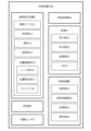
- FIG. 1 is a functional block diagram showing an embodiment of a seasoning liquid supplying device according to the present invention.
- 4 is a schematic diagram showing a supply path of seasoning liquid by the supply device.
- FIG. FIG. 4 is a schematic diagram showing a positional relationship between a temperature sensor and a suction pipe provided in the supply device inside a storage tank.
- FIG. 5A and 5B are schematic diagrams showing the inclination of a shielding plate provided in the supply device.
- 13 is a perspective view showing a state in which a holding portion of the supply device is moved upward.
- FIG. FIG. 4 is a perspective view showing another embodiment of the supply device.
- 5 is a schematic diagram showing an attachment position of a position adjustment unit in a housing of the supply device.
- FIG. FIG. 11 is a perspective view showing still another embodiment of the supply device.
- the following explanation uses a temperature measuring device that measures the temperature of ramen soup stored in a cylinder and heated, and a supplying device that supplies the soup stored in the cylinder from the cylinder to the rice bowl in which the ramen is stored. That is, the temperature measuring device and supplying device are installed in the kitchen of a ramen shop.
- ramen is an example of food and drink in the present invention.
- Ramen soup is an example of seasoning liquid in the present invention.
- the cylinder is an example of a storage tank in which seasoning liquid is stored in the present invention.
- the rice bowl is an example of a container that contains food and drink.
- the seasoning liquid in this invention is not limited to ramen soup.
- FIG. 1 is a functional block diagram showing an embodiment of a seasoning liquid supplying device and a temperature measuring device according to the present invention.
- Supply device 100 (hereinafter referred to as "device 100") is an example of a seasoning liquid supply device according to the present invention.
- Device 100 supplies soup stored in a pot at a specified time and in a specified amount to a rice bowl.
- device 100 supplies soup from the pot to the bowls based on a control signal from a control system (not shown) installed inside the ramen shop.
- a control system (not shown) installed inside the ramen shop.
- the timing at which device 100 supplies soup to the bowls is determined by the control system.
- the control system for example, receives order information from customers and controls the operation of device 100 based on the order information.
- the device 100 includes a temperature measuring device 1, a liquid delivery unit 2, a flow rate sensor 3, a supply control unit 4, a pipe 5, and a heating device 6.
- the temperature measuring device 1 (hereinafter referred to as "device 1") provided in the device 100 is an example of a seasoning liquid temperature measuring device according to the present invention.
- Device 1 measures the temperature of soup stored in a pot and being heated. The measured temperature is used to control the heating of the soup in the pot.
- the liquid delivery unit 2 delivers the soup stored in the pot from the pot to the bowl.
- the liquid delivery unit 2 is a tubing pump.
- Flow sensor 3 measures the flow rate of soup sent from the pot to the bowl.
- Flow sensor 3 is a Coriolis flow meter.
- the flow sensor in the present invention may be an ultrasonic flow meter.
- the supply control unit 4 controls the supply of soup from the pot to the bowl based on the flow rate measured by the flow sensor 3.
- the supply control unit 4 controls the supply of soup from the pot to the bowl by controlling the opening and closing of a valve 54, which will be described later, based on the flow rate measured by the flow sensor 3.
- the supply control unit 4 is realized by a control program that runs on a PLC (Programmable Logic Controller).
- the supply control unit in the present invention is not limited to a control program that runs on a PLC.
- the supply control unit may be anything that can control the opening and closing of the valve 54 described below, and may be realized, for example, by a control program that runs on a microcomputer or FPGA (Field Programmable Gate Array).
- the soup that is supplied from the pot to the bowl passes through the piping 5.
- the piping 5 includes an intake pipe 51, an exhaust pipe 52, a return pipe 53, and a valve 54.
- the suction pipe 51 is a pipe through which the soup in the pot passes as it is sucked up by the liquid delivery unit 2. One end of the suction pipe 51 is placed inside the pot. The other end of the suction pipe 51 is connected to a valve 54. The flow rate of the soup passing through the suction pipe 51 is measured by a flow sensor 3.
- the discharge pipe 52 is a pipe through which the soup that has passed through the valve 54 passes. One end of the discharge pipe 52 is connected to the valve 54. The other end of the discharge pipe 52 is disposed near the bowl. The soup that has passed through the discharge pipe 52 is supplied to the bowl.
- the return pipe 53 is a pipe through which the soup that has passed through the suction pipe 51 but has not passed through the valve 54 passes.
- One end of the return pipe 53 is connected to the valve 54.
- the other end of the return pipe 53 is placed inside the pot.
- the soup that has passed through the return pipe 53 is supplied (returned) to the pot.
- the valve 54 switches the connection between the suction pipe 51 and the exhaust pipe 52 or the return pipe 53. That is, the valve 54 switches the connection between the suction pipe 51 and the exhaust pipe 52, or the connection between the suction pipe 51 and the return pipe 53.
- the valve 54 is a pinch valve.
- the heating device 6 heats the soup stored in the pot.
- the heating device 6 is an induction heating heater.
- the heating device 6 includes a heating unit 61, a heating control unit 62, a memory unit 63, and an operation unit 64.
- the heating unit 61 inductively heats the soup stored in the pot.
- the heating unit 61 has a heating coil that heats the bottom of the pot (made of metal), which is a magnetic body. In other words, the soup stored in the pot is heated by heating the bottom of the pot with the heating coil.
- the heating control unit 62 controls the heating output of the heating unit 61 so that the temperature of the soup stored in the pot converges to a predetermined temperature (target temperature: for example, 95°C) without exceeding the predetermined temperature (upper limit temperature: for example, 100°C). That is, the heating control unit 62 controls the supply of current to the heating coil of the heating unit 61 (PID control). That is, the heating control unit 62 determines the on/off of the supply of current to the heating coil, the current value of the current supplied, and the like.
- the heating control unit 62 is realized by a computer program that runs on a microcomputer. The heating control unit 62 controls the heating output of the heating unit 61 based on the temperature measured by the device 1, the target temperature stored in the memory unit 63, adjustment parameters for PID control, and the like.
- the target temperature is set by the user based on, for example, the boiling point of the soup, the type of soup, the amount of soup stored in the pot, the change in room temperature in the kitchen in which the device 100 is installed, etc.
- the target temperature is lower than the boiling point (upper limit temperature) of the soup.
- the temperature of the soup stored in the pot converges to the target temperature through PID control by the heating control unit 62.
- the manner in which the temperature of the soup stored in the pot converges to the target temperature may be, for example, a manner in which the temperature converges to the target temperature without exceeding the target temperature (so as not to overshoot), or a manner in which the temperature converges to the target temperature without exceeding the upper limit temperature even if the target temperature is exceeded.
- the memory unit 63 stores information necessary for the operation of the heating device 6.
- the information stored in the memory unit 63 includes the target temperature and adjustment parameters for PID control by the heating control unit 62.
- the storage unit in the present invention may be, for example, a portable storage medium such as a hard disk drive (HDD), a solid state drive (SSD), or a flash memory, or other non-temporary storage medium, or a random access memory (RAM) or other temporary storage medium, etc.
- a portable storage medium such as a hard disk drive (HDD), a solid state drive (SSD), or a flash memory, or other non-temporary storage medium, or a random access memory (RAM) or other temporary storage medium, etc.
- the operation unit 64 receives operation information required for the operation of the heating device 6 from the user of the device 100 (a staff member at the ramen shop).
- the user operates the operation unit 64 to operate the device 100. For example, when the user wishes to change the target temperature stored in the memory unit 63, the user inputs the changed target temperature from the operation unit 64.
- the operation unit 64 is configured as a touch panel.
- the device 1 includes a temperature sensor 11, a holding unit 12, a housing 13, a shielding plate 14, and a position adjustment unit 15.
- the temperature sensor 11 is placed inside the pot and measures the temperature of the soup stored in the pot.
- the temperature sensor 11 is a sheathed thermocouple (e.g., a K-type thermocouple or a T-type thermocouple) in which a pair of thermocouple wires is housed in a metal sheath.
- the holding unit 12 holds the temperature sensor 11. Details of the configuration of the holding unit 12 will be described later.
- the housing 13 houses the heating device 6 that heats the soup stored in the pot.
- the shielding plate 14 is placed above the cylinder. Details of the shielding plate 14 will be described later.
- the position adjustment unit 15 makes it possible to adjust the position of the temperature sensor 11 with respect to the pot.
- the position adjustment portion 15 includes a rail portion 16 , a position fixing portion 17 , and a stopper 18 .
- the rail portion 16 (for example, an aluminum frame FSL-L type manufactured by Sugatsune Kogyo Co., Ltd.) moves the holding portion 12 so that the temperature sensor 11 can move back and forth between the inside and outside of the storage tank.
- the position fixing part 17 (for example, a free slide lock FSL-V36 manufactured by Sugatsune Kogyo Co., Ltd.) fixes the position of the holding part 12 relative to the rail part 16.
- the position fixing part 17 includes a slide part that is placed within the rail of the rail part 16, and a restriction operation part that operates the restriction of the movement of the slide part within the rail.
- the restriction operation part When the user operates the restriction operation part to enable the slide part to move within the rail, the position fixing part 17 becomes movable along the rail of the rail part 16.
- the restriction operation part to disable the slide part from moving within the rail the position fixing part 17 becomes unable to move along the rail of the rail part 16.
- the position fixing portion 17 is coupled to the holding portion 12. That is, when the restricting operation portion of the position fixing portion 17 is operated and the position fixing portion 17 moves along the rail of the rail portion 16, the holding portion also moves along the rail of the rail portion 16. As described above, the holding portion 12 holds the temperature sensor 11. That is, when the restricting operation portion of the position fixing portion 17 is operated and the position fixing portion 17 moves along the rail of the rail portion 16, the temperature sensor 11 also moves along the rail of the rail portion 16.
- the stoppers 18 (for example, stopper FSL-S4 manufactured by Sugatsune Kogyo Co., Ltd.) are arranged within the rail of the rail section 16 so that the sliding section of the position fixing section 17 can abut against them.
- the stoppers 18 are arranged on both ends of the rail. In other words, the stoppers 18 define the range of movement of the position fixing section 17 that can move along the rail.
- the direction of movement of the position fixing part 17, which is movable along the rail of the rail part 16, is the vertical direction (the up-down direction on the paper surface of FIG. 3 described later). That is, the stopper 18 arranged at one end (upper end) of the rail determines the upper limit position of the position fixing part 17, and the stopper 18 arranged at the other end (lower end) of the rail determines the lower limit position of the position fixing part 17. In other words, the stopper 18 determines the upper limit and lower limit positions of the temperature sensor 11 and the suction pipe 51 connected to the position fixing part 17. In other words, the user can position the temperature sensor 11 and the suction pipe 51 connected to the position fixing part 17 to a predetermined position in the vertical direction by moving the position fixing part 17 until the position fixing part 17 abuts against the stopper 18.
- the stopper 18 located at the upper end of the rail is the end cap of the rail (for example, end cap FSL-EC manufactured by Sugatsune Kogyo Co., Ltd.).
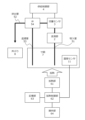
- FIG. 2 is a schematic diagram showing the supply path of soup by the device 100. The figure shows that soup stored in a pot 7 is sucked into the liquid delivery section 2 , passes through a suction pipe 51 , a valve 54 and a discharge pipe 52 , and is supplied to a bowl 8 .
- the figure shows that the flow sensor 3 measures the flow rate of soup passing through the suction pipe 51, and the measurement result (a signal indicating the flow rate) is output to the supply control unit 4.
- the figure shows that the supply control unit 4 controls the opening and closing of the valve 54 based on the flow rate measured by the flow sensor 3.
- the valve 54 When the valve 54 is open, the soup from the suction pipe 51 passes through the discharge pipe 52.
- the valve 54 When the valve 54 is closed, the soup from the suction pipe 51 passes through the return pipe 53 and returns to the pot 7.
- the figure shows that the measurement result (signal indicating the temperature) of the soup stored in the pot 7 measured by the temperature sensor 11 is output to the heating control unit 62.
- the figure shows that the heating control unit 62 controls the heating output of the heating unit 61 based on the measurement result from the temperature sensor 11 and information (upper limit temperature and target temperature) stored in the memory unit 63.
- the figure shows that the heating unit 61 heats the outside of the bottom (bottom surface) of the pot 7, thereby heating the soup inside the pot 7.
- the upper limit temperature is the boiling point of the soup.
- the target temperature is a temperature lower than the upper limit temperature, and is the temperature at which the ramen served in a bowl to the customer has the desired flavor.
- the heating control unit 62 controls the heating output of the heating unit 61 based on the change in the temperature of the soup in the pot 7 measured by the temperature sensor 11, which is stored in the memory unit 63, so that the temperature of the soup in the pot 7 does not exceed the upper limit temperature.
- the temperature sensor 11 measures the temperature at the hottest position in the pot 7.
- the heating control unit 62 heats the soup in the pot 7 so that the soup does not boil and generate air bubbles.
- the flow sensor 3 can measure an accurate flow rate.
- the heating control unit 62 controls the heating output of the heating unit 61 based on the change in the temperature of the soup in the pot 7 measured by the temperature sensor 11 which is stored in the memory unit 63, so that the temperature of the soup in the pot 7 becomes the target temperature. That is, when the temperature measured by the temperature sensor 11 is lower than the target temperature, the heating control unit 62 increases the heating output of the heating unit 61 so that the temperature of the soup in the pot 7 rises.
- the heating control unit 62 reduces the heating output of the heating unit 61 so that the temperature of the soup in the pot 7 drops or the rate of rise slows.
- the heating control unit 62 controls the heating output of the heating unit 61 so that the temperature of the soup in the pot 7 converges to the target temperature without exceeding the upper limit temperature, even if there are factors that cause the temperature of the soup in the pot 7 to fluctuate, such as the air temperature in the kitchen where the pot 7 is located or the replenishment of soup to the pot 7.
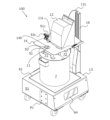
- FIG. 3 is a perspective view of the device 100.
- the figure shows that the cylinder 7 is placed in the heating section 61 of the heating device 6 housed in the housing 13.
- the housing 13 is provided with heat-resistant glass (not shown) (e.g., Fairlight (registered trademark) manufactured by Nippon Electric Glass Co., Ltd.) that covers the surface of the heating section 61.
- the bottom surface of the cylinder 7 is placed on the surface of the heat-resistant glass.
- the figure shows that the shielding plate 14 has a hole 14h that allows soup to be replenished into the pot 7 while the pot 7 is placed on the device 100. That is, the user removes the lid (the lid 71 of the two halves, lid 71 and lid 72) covering the opening of the cylindrical pot 7 from the cylindrical pot 7. The hole 14h is located above a part of the opening of the cylindrical pot 7 from which the lid 71 has been removed. The user then inserts a funnel into hole 14h. The funnel is placed into hole 14h. Next, the user pours the refill soup (stored in the refill pot) into the funnel from above the funnel inserted into the hole 14h. The refill soup poured into the funnel passes through the funnel and the opening of the pot 7, and is supplied to the inside of the pot 7. Next, when the user has completed refilling the soup, he or she covers the opening of the stockpot 7 with the lid 71 and removes the funnel from the hole 14h.
- the lid the lid 71 of the two halves, lid 71 and lid 72
- the shielding plate does not have to have a hole through which the funnel is inserted.
- the user removes the lid 71 from the opening of the stockpot 7 and pours the soup for refilling directly into the inside of the stockpot 7 through the part of the opening of the stockpot 7 that was covered by the lid 71.
- the figure shows that joints 51C and 53C are disposed on the shielding plate 14.
- the joint 51C constitutes a part of the suction pipe 51.
- One end of the suction pipe 51 arranged inside the cylindrical body 7 is connected to the joint 51C.
- One end of a suction pipe (not shown) that is connected to the liquid delivery unit 2 housed in the holding unit 12 is connected to the joint 51C.
- the joint 53C constitutes a part of the return pipe 53.
- One end of the return pipe 53 arranged inside the cylindrical body 7 is connected to the joint 53C.
- One end of a return pipe (not shown) connected to the valve 54 is connected to the joint 53C.
- the figure shows that the signal line 11L is inserted inside the rail portion 16.
- Signal line 11L transmits a signal corresponding to the temperature of the soup stored in pot 7 measured by temperature sensor 11 to heating control unit 62.
- One end of signal line 11L is connected to temperature sensor 11 arranged inside pot 7.
- the other end of signal line 11L is connected to heating control unit 62 housed in housing 13.
- the temperature of the soup stored in pot 7 is measured based on the magnitude of the thermoelectromotive force generated according to the temperature difference (T1-T2) between the temperature (T1) at one end of signal line 11L arranged inside pot 7 and the temperature (T2) at the other end of signal line 11L connected to heating control unit 62.
- the figure shows that a mounting point P1 (an area surrounded by a dashed line in the figure) is disposed on a side surface S1 of the housing 13.
- the mounting location P1 is a location where the rail portion 16 is attached to the housing 13.
- the figure shows that six bolts for attaching the rail portion 16 to the housing 13 are arranged at the mounting location P1 on the side surface S1.
- the housing 13 has two locations where the rail portion 16 is attached.
- the mounting location P1 is the first mounting location in the present invention. The user selects one of the two locations (P1, P2) on the housing 13 as the location where the rail portion 16 is attached, depending on the layout of the kitchen in which the device 100 is installed (including the orientation and shape of the equipment in the kitchen, the movement of the staff in the kitchen, etc.). Note that the figure shows a case where the rail portion 16 is attached to the second mounting location (P2 in FIG. 8) of the housing 13.
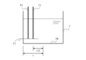
- Figure 4 is a schematic diagram showing the positional relationship between the temperature measuring part of the temperature sensor 11 and the intake port of the intake pipe 51 inside the cylinder 7.
- the figure shows that the height direction (up and down direction on the paper) positions of the bottom ends of the temperature sensor 11 and the suction pipe 51 are aligned at the position indicated by the dashed line L1.
- the temperature sensor 11 measures the temperature near the bottom end of the temperature sensor 11. In other words, the temperature measuring part of the temperature sensor 11 is located at the bottom end of the temperature sensor 11.
- the suction pipe 51 sucks soup from the bottom end of the suction pipe 51. In other words, the suction port of the suction pipe 51 is located at the bottom end of the suction pipe 51.
- the temperature of the soup stored in the pot 7 is higher the closer it is to the bottom surface 7B of the pot 7, which is closer to the heating section 61.
- the temperature sensor 11 measures the temperature of the soup stored in the pot 7 that is close to the temperature of the soup that is sucked in through the suction pipe 51 and supplied to the bowl.
- the vertical positions of the temperature sensor 11 and the suction pipe 51 can be adjusted by the user by operating the position adjustment unit 15. That is, when the soup stored in the pot 7 is being heated so that it can be supplied to the rice bowl 8, the user operates the position fixing unit 17 to move the position fixing unit 17 downward until the position fixing unit 17 abuts against the stopper 18 arranged at the lower end of the rail portion 16, thereby fixing the position of the position fixing unit 17 relative to the rail portion 16.
- the lower end of the temperature sensor 11 and the suction pipe 51 are positioned near the inner surface of the bottom surface 7B of the pot 7 (the inner surface of the pot 7), which is the hottest part inside the pot 7 (for example, 5 mm above the inner surface of the bottom surface 7B).
- the figure shows that the temperature sensor 11 is positioned at the midpoint of the radius r of the bottom surface 7B of the bottomed cylindrical drum 7 (a position r/2 from the center point of the bottom surface 7B).
- the radial position of the bottom surface 7B of the temperature sensor 11 is determined by the position adjustment unit 15, similar to the vertical position of the temperature sensor 11 described above.
- the temperature sensor 11 is attached to the shielding plate 14 so that it is positioned at a predetermined radial position of the bottom surface 7B.
- the midpoint of the radius r of the bottom surface 7B is the hottest position inside the cylinder 7.
- the hottest position inside the cylinder 7 in the radial direction of the bottom surface 7B is determined based on the configuration of the heating unit 61 (such as the arrangement of the coils) and the position where the cylinder 7 is placed on the heating unit 61.
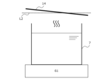
- FIG. 5 is a schematic diagram showing the inclination of the shielding plate 14. As shown in FIG. The figure shows that the shielding plate 14 is disposed at an angle to the horizontal (the direction indicated by the dashed line L2 in the figure). When the temperature sensor 11 is disposed inside the cylinder 7, the shielding plate 14 is disposed above the cylinder 7. A part of the soup stored in the cylinder 7 is heated by the heating section 61 and becomes steam. The steam rises to the top of the cylinder 7 and hits the back surface of the shielding plate 14 (the surface on the lower side of the paper). The steam that hits the shielding plate 14 becomes condensed water. Because the shielding plate 14 is disposed at an angle to the horizontal direction, the condensed water moves along the bottom surface of the shielding plate 14 (to the right on the paper) and falls to the outside of the cylinder 7.
- the shielding plate 14 prevents the condensed water from mixing into the stockpot 7.
- the angle of inclination of the shielding plate 14 relative to the horizontal and the size of the shielding plate 14 are set so that the condensed water does not mix into the stockpot 7.
- the shielding plate 14 also prevents oil from the motor (which drives the agitator described below) housed in the holding part 12 located above the shielding plate 14 from leaking out of the holding part 12 and getting into the inside of the cylindrical barrel 7. In other words, the shielding plate 14 prevents foreign matter from getting into the inside of the cylindrical barrel 7.
- FIG. 6 is a perspective view of the device 100. This figure shows the state in which the holding portion 12 has moved upward along the rail portion 16.
- the user moves the temperature sensor 11, suction pipe 51, return pipe 53, and stirrer SB, which are disposed inside the pot 7, to the outside of the pot 7, and then removes the pot 7, which is enclosed in the housing 13, from the device 100.
- the stirrer SB is disposed inside the pot 7 and includes propeller blades that stir the soup stored in the pot 7. The propeller blades are disposed at the bottom end of the stirrer SB.
- the user operates the position fixing part 17 (not shown) to move the position fixing part 17 upward until the position fixing part 17 abuts against the stopper 18 (not shown) located at the upper end of the rail part 16, thereby fixing the position of the position fixing part 17 relative to the rail part 16.
- the temperature sensor 11, suction pipe 51, return pipe 53, and agitator SB which were located inside the cylindrical body 7, are retracted to the outside of the cylindrical body 7. The user can then easily remove the cylindrical body 7 from the device 100.
- the user installs a new cylinder 7 in the device 100 (places it on the housing 13).
- the user then operates the position fixing part 17 to move the position fixing part 17 downward until the position fixing part 17 abuts against the stopper 18 located at the lower end of the rail part 16, thereby fixing the position of the position fixing part 17 relative to the rail part 16.
- the temperature sensor 11 and the lower end of the suction pipe 51 are positioned at predetermined positions inside the cylinder 7.
- FIG. 7 is a perspective view showing another embodiment of a supply device according to the present invention. This figure shows that the rail portion 16 is attached to the first attachment position (P1, see FIG. 3) on the side surface S1 of the housing 13, as described above.
- Figure 8 is a schematic diagram of the housing 13 in a plan view, showing the mounting position of the rail portion 16 on the housing 13.
- the figure shows that the housing 13 has a first surface S1 and a second surface S2, that the first mounting location P1 is located on the first surface S1, and that the second mounting location P2 is located on the second surface S2.
- the figure shows that the first mounting location P1 and the second mounting location P2 are located at opposing positions across the position of the heating section 61 (heating device 6) in a plan view of the housing. Note that in the figure, the first mounting location P1 and the second mounting location P2 are indicated by black circles for ease of explanation.
- the figure shows that the heating section 61 (heating device 6) is positioned on the housing on an imaginary line L3 that connects the first mounting position P1 and the second mounting position P2.
- FIG. 9 is a perspective view of a liquid seasoning supplying device and a temperature measuring device according to another embodiment of the present invention.
- Device 200 is an example of another embodiment of the seasoning liquid supply device according to the present invention.
- Device 200 differs from device 100 in that holding unit 120 constituting the temperature measuring device is different from holding unit 12 constituting device 1.
- the figure shows that the holding part 120 that holds the temperature sensor 11 is connected to the position fixing part 17.
- the figure shows that the holding part 120 is plate-shaped, unlike the holding part 12.
- the holding part 120 holds only the temperature sensor 11.
- the holding part 120 does not hold the joints that form part of the piping (joints 51C, 53C in FIG. 3) or the agitator (agitator SB in FIG. 6).
- the seasoning liquid temperature measuring device of the present invention only needs to include a holding section that holds the temperature sensor 11, allowing the temperature sensor 11 to move back and forth between the inside and outside of the pot 7, and a position adjustment section that allows the position of the temperature sensor 11 to be adjusted relative to the pot 7.
- the holding section may or may not hold other components (for example, the aforementioned joint or agitator) in addition to the temperature sensor 11.
- the position adjustment unit 15 can position the temperature measuring portion of the temperature sensor 11 at the hottest position in the cylinder 7.
- the temperature measuring portion of the temperature sensor 11 is positioned at a desired position by the user moving the position fixing unit 17 downward until the position fixing unit 17 abuts against the stopper 18. In other words, the positioning of the temperature sensor 11 is easily achieved.
- the heating control unit 62 realizes heating of the soup in the pot 7 so that the temperature of the soup in the pot 7 converges to the target temperature without exceeding the upper limit temperature.
- the flow rate sensor 3 can measure the flow rate accurately.
- the temperature measuring portion of the temperature sensor 11 is disposed at the same height as the suction port of the suction pipe 51 within the pot 7. That is, the temperature sensor 11 measures a temperature of the soup stored in the pot 7 that is close to the temperature of the soup that is sucked in through the suction pipe 51 and supplied to the bowl. Therefore, the device 1 and devices 100 and 200 can supply the soup stored and heated in the pot 7 to the bowl at an appropriate temperature and in an appropriate amount.
- the temperature sensor 11 and other sensors placed inside the cylinder 7 can be positioned to the desired position, i.e., a position where the temperature sensor 11 and other sensors do not get in the way when the cylinder 7 is replaced, by the user moving the position fixing portion 17 upward until the position fixing portion 17 abuts against the stopper 18. Therefore, the device 1 and the devices 100 and 200 facilitate use by the user, such as by replacing the drum 7 and cleaning the device 1 and the devices 100 and 200.
- the temperature sensor 11 is disposed inside the pot 7, not outside the pot 7. By disposing the temperature sensor 11 inside the pot 7, the temperature sensor 11 can directly measure the temperature of the soup stored inside the pot 7.
- the temperature measured by temperature sensor 11 will be different from the temperature of the soup stored inside cylinder 7.
- the responsiveness of the temperature sensor 11 arranged inside cylinder 7 in measuring the soup temperature is better than the responsiveness of the temperature sensor 11 arranged outside cylinder 7 in measuring the soup temperature.
- the accuracy of the soup temperature control by heating control unit 62 using temperature sensor 11 arranged inside cylinder 7 is higher than the accuracy of the soup temperature control by heating control unit 62 using temperature sensor 11 arranged outside cylinder 7.
- the seasoning liquid temperature measuring device is A device (e.g., device 100, 200) for measuring the temperature of a seasoning liquid (e.g., ramen soup) stored in a storage tank (e.g., a cylinder 7) and heated, A temperature sensor (e.g., temperature sensor 11) disposed inside the storage tank to measure the temperature of the seasoning liquid stored in the storage tank; A holder (e.g., holder 12/120) for holding the temperature sensor; A position adjustment unit (e.g., a position adjustment unit 15) that adjusts the position of the temperature sensor relative to the storage tank; Is there, It is characterized by:
- the position adjustment unit is A rail portion (e.g., rail portion 16) that moves the holding portion so that the temperature sensor can advance and retreat between the inside and the outside of the storage tank; A position fixing portion (e.g., a position fixing portion 17) that fixes the position of the holding portion relative to the rail portion;
- the present invention may also include:
- the rail portion is A stopper (e.g., stopper 18) for positioning the temperature sensor relative to the reservoir;
- the present invention may also include:
- the seasoning liquid temperature measuring device is A housing (e.g., housing 13) to which the rail portion is attached; and the housing includes an attachment portion to which the rail portion is attached,
- the attachment point is A first attachment point (e.g., a first attachment point P1); a second attachment point (e.g., second attachment point P2); It may include.
- the seasoning liquid temperature measuring device is The housing accommodates a heating device (e.g., heating device 6) that heats the seasoning liquid inside the storage tank,
- a heating device e.g., heating device 6
- the first mounting location and the second mounting location may be located at opposing positions (e.g., on the first surface S1 and the second surface S2) across the position of the heating device in a plan view of the housing.
- the arrangement position of the heating device in the housing may be on a virtual line (e.g., a virtual line L3) connecting the first attachment point and the second attachment point.
- a virtual line e.g., a virtual line L3 connecting the first attachment point and the second attachment point.
- the seasoning liquid temperature measuring device is A shielding plate (e.g., shielding plate 14) disposed above the storage tank; and When the temperature sensor is disposed inside the storage tank, the shielding plate may be disposed obliquely relative to the horizontal.
- shielding plate e.g., shielding plate 14
- the temperature sensor When the temperature sensor is disposed within the interior of the reservoir, The holding portion is disposed above the shielding plate, The temperature sensor may be disposed below the shielding plate.
- the shielding plate is a hole (e.g., hole 14h) through which a funnel is disposed, through which a replenishment liquid is passed to replenish the reservoir;
- the present invention may also include:
- the seasoning liquid supply device comprises: A device for supplying a seasoning liquid (e.g., soup) contained in food or drink (e.g., ramen) to a container (e.g., a bowl 8) in which the food or drink is contained, A liquid delivery unit (e.g., liquid delivery unit 2) that delivers the liquid seasoning from a storage tank (e.g., a cylinder 7) in which the liquid seasoning is stored to the container; A flow rate sensor (e.g., flow rate sensor 3) that measures the flow rate of the seasoning sent from the storage tank to the container; A supply control unit (e.g., a supply control unit 4) that controls the supply of the seasoning liquid from the storage tank to the container based on the flow rate measured by the flow rate sensor; A heating device (for example, a heating device 6) that heats the seasoning liquid stored in the storage tank; A temperature measuring device (e.g., device 1) for measuring the temperature of the seasoning liquid stored in the storage tank; and The temperature measuring
- the heating device includes: A heating unit (for example, heating unit 61) that heats the seasoning liquid stored in the storage tank; A heating control unit (e.g., a heating control unit 62) that controls the heating output of the heating unit; Equipped with The heating control unit may control the heating output based on a change in the temperature measured by the temperature measuring device.
- a heating unit for example, heating unit 61
- a heating control unit e.g., a heating control unit 62
- the heating control unit may control the heating output based on a change in the temperature measured by the temperature measuring device.
- the heating device includes: A memory unit (e.g., memory unit 63) that stores a target temperature (e.g., 95°C) of the seasoning liquid stored in the storage tank; Equipped with The target temperature is lower than the boiling point of the seasoning liquid,
- the heating control unit may control the heating output so that the temperature measured by the temperature measuring device converges to the target temperature.
- the heating unit heats the outside of the bottom of the storage tank (for example, the bottom surface 7B of the cylinder 7), A height position of a temperature measuring portion of the temperature sensor within the interior of the storage tank may be near the inside of the bottom of the storage tank.
- a pipe (for example, a pipe 5) through which the seasoning liquid stored in the storage tank passes; and One end of the pipe is disposed inside the storage tank, A height position of the one end within the interior may be substantially equal to a height position of the temperature sensor within the interior.
- the piping includes: A suction pipe (e.g., suction pipe 51) arranged on the storage tank side; A discharge pipe (e.g., discharge pipe 52) disposed on the container side; a valve (e.g., valve 54) disposed between the intake pipe and the exhaust pipe; Equipped with The supply control unit may control the supply of the liquid seasoning from the storage tank to the container by controlling opening and closing of the valve.
- a suction pipe e.g., suction pipe 51
- a discharge pipe e.g., discharge pipe 52
- a valve e.g., valve 54
Landscapes
- Physics & Mathematics (AREA)
- General Physics & Mathematics (AREA)
- Commercial Cooking Devices (AREA)
- Cookers (AREA)
Abstract
Selon la présente invention, un liquide d'assaisonnement chauffé et retenu dans un réservoir de rétention est fourni à un récipient contenant un aliment ou une boisson, à une température appropriée et en une quantité appropriée. Un dispositif de mesure de température (1) selon la présente invention est destiné à mesurer la température d'un liquide d'assaisonnement chauffé et retenu dans un réservoir de rétention (7), et comprend : un capteur de température (11) qui est disposé à l'intérieur du réservoir de rétention et qui mesure la température du liquide d'assaisonnement retenu dans le réservoir de rétention ; une unité de maintien (12) qui maintient le capteur de température ; et une unité de réglage de position (15) qui permet le réglage de la position du capteur de température par rapport au réservoir de rétention.
Priority Applications (2)
| Application Number | Priority Date | Filing Date | Title |
|---|---|---|---|
| PCT/JP2023/004443 WO2024166322A1 (fr) | 2023-02-09 | 2023-02-09 | Dispositif de mesure de température et appareil d'alimentation pour liquide d'assaisonnement |
| JP2024576015A JP7690244B2 (ja) | 2023-02-09 | 2023-02-09 | 調味液の温度測定装置と供給装置 |
Applications Claiming Priority (1)
| Application Number | Priority Date | Filing Date | Title |
|---|---|---|---|
| PCT/JP2023/004443 WO2024166322A1 (fr) | 2023-02-09 | 2023-02-09 | Dispositif de mesure de température et appareil d'alimentation pour liquide d'assaisonnement |
Publications (1)
| Publication Number | Publication Date |
|---|---|
| WO2024166322A1 true WO2024166322A1 (fr) | 2024-08-15 |
Family
ID=92262146
Family Applications (1)
| Application Number | Title | Priority Date | Filing Date |
|---|---|---|---|
| PCT/JP2023/004443 Ceased WO2024166322A1 (fr) | 2023-02-09 | 2023-02-09 | Dispositif de mesure de température et appareil d'alimentation pour liquide d'assaisonnement |
Country Status (2)
| Country | Link |
|---|---|
| JP (1) | JP7690244B2 (fr) |
| WO (1) | WO2024166322A1 (fr) |
Citations (2)
| Publication number | Priority date | Publication date | Assignee | Title |
|---|---|---|---|---|
| JPH0872991A (ja) * | 1994-09-02 | 1996-03-19 | Yamato Seisakusho:Kk | スープ供給装置 |
| CN214927150U (zh) * | 2021-04-27 | 2021-11-30 | 广州畅德科技有限公司 | 一种测温结构和光固化装置 |
Family Cites Families (3)
| Publication number | Priority date | Publication date | Assignee | Title |
|---|---|---|---|---|
| JP4538491B2 (ja) * | 2007-12-06 | 2010-09-08 | 有限会社ナカイ | ラーメンスープ材料の煮出し装置 |
| JP5931142B2 (ja) * | 2014-08-27 | 2016-06-08 | 日本洗浄機株式会社 | だし汁製造装置及びだし汁製造方法 |
| EP3542645A1 (fr) * | 2016-11-21 | 2019-09-25 | Techno System Co.,Ltd. | Appareil d'alimentation en soupe |
-
2023
- 2023-02-09 JP JP2024576015A patent/JP7690244B2/ja active Active
- 2023-02-09 WO PCT/JP2023/004443 patent/WO2024166322A1/fr not_active Ceased
Patent Citations (2)
| Publication number | Priority date | Publication date | Assignee | Title |
|---|---|---|---|---|
| JPH0872991A (ja) * | 1994-09-02 | 1996-03-19 | Yamato Seisakusho:Kk | スープ供給装置 |
| CN214927150U (zh) * | 2021-04-27 | 2021-11-30 | 广州畅德科技有限公司 | 一种测温结构和光固化装置 |
Also Published As
| Publication number | Publication date |
|---|---|
| JP7690244B2 (ja) | 2025-06-10 |
| JPWO2024166322A1 (fr) | 2024-08-15 |
Similar Documents
| Publication | Publication Date | Title |
|---|---|---|
| EP3220787B1 (fr) | Dispositif de traitement de liquides par le biais de vapeur | |
| US8707862B1 (en) | Cooking apparatus and method | |
| RU2387360C2 (ru) | Машина и способ для приготовления напитка, такого как кофе | |
| CN102946776B (zh) | 用于控制热调节装置的能量传输的设备和方法 | |
| TW202010462A (zh) | 自動調理機 | |
| US9763537B2 (en) | Hot beverage maker | |
| JP7690244B2 (ja) | 調味液の温度測定装置と供給装置 | |
| JP2011027619A (ja) | 温度測定システム及び温度測定方法、並びに、これらを用いた溶出試験器の温度制御システム及び温度制御方法 | |
| US20090293734A1 (en) | Beverage maker having a thermostat for controlling the operation of heating means for heating water | |
| CA2764596A1 (fr) | Systeme et methode de cuillere chauffee a economie d'eau pour ustensile d'aliments et de breuvages destines a la consommation humaine | |
| JP4794968B2 (ja) | 飲料水供給装置 | |
| KR101258070B1 (ko) | 분유 공급장치 | |
| CN114206180A (zh) | 加热的食物处理器 | |
| JP4176047B2 (ja) | 粘度計 | |
| KR20220056926A (ko) | 스마트 라면조리기 | |
| GB2185303A (en) | Heating a plurality of liquids | |
| JP6546406B2 (ja) | 蒸気発生装置 | |
| KR100727160B1 (ko) | 쿡탑 구조 | |
| JP6781575B2 (ja) | 調理器 | |
| WO2026028425A1 (fr) | Dispositif de gestion de température pour assaisonnement liquide | |
| JP2023168923A (ja) | 加熱調理器及び加熱調理方法 | |
| EP4255265A1 (fr) | Machine permettant de chauffer et d'agiter une substance alimentaire liquide dotée d'un dispositif d'arrêt | |
| GB2468516A (en) | Dispensing apparatus | |
| KR20200001561U (ko) | 통합형 온수탱크가 구비된 라면 조리기 | |
| JPH02299614A (ja) | ジャー炊飯器 |
Legal Events
| Date | Code | Title | Description |
|---|---|---|---|
| 121 | Ep: the epo has been informed by wipo that ep was designated in this application |
Ref document number: 23921153 Country of ref document: EP Kind code of ref document: A1 |
|
| WWE | Wipo information: entry into national phase |
Ref document number: 2024576015 Country of ref document: JP |
|
| NENP | Non-entry into the national phase |
Ref country code: DE |
|
| 122 | Ep: pct application non-entry in european phase |
Ref document number: 23921153 Country of ref document: EP Kind code of ref document: A1 |