WO2024166322A1 - Temperature measurement device and supply apparatus for seasoning liquid - Google Patents
Temperature measurement device and supply apparatus for seasoning liquid Download PDFInfo
- Publication number
- WO2024166322A1 WO2024166322A1 PCT/JP2023/004443 JP2023004443W WO2024166322A1 WO 2024166322 A1 WO2024166322 A1 WO 2024166322A1 JP 2023004443 W JP2023004443 W JP 2023004443W WO 2024166322 A1 WO2024166322 A1 WO 2024166322A1
- Authority
- WO
- WIPO (PCT)
- Prior art keywords
- temperature
- storage tank
- seasoning
- liquid
- heating
- Prior art date
- Legal status (The legal status is an assumption and is not a legal conclusion. Google has not performed a legal analysis and makes no representation as to the accuracy of the status listed.)
- Ceased
Links
Images


Classifications
-
- G—PHYSICS
- G01—MEASURING; TESTING
- G01K—MEASURING TEMPERATURE; MEASURING QUANTITY OF HEAT; THERMALLY-SENSITIVE ELEMENTS NOT OTHERWISE PROVIDED FOR
- G01K1/00—Details of thermometers not specially adapted for particular types of thermometer
- G01K1/14—Supports; Fastening devices; Arrangements for mounting thermometers in particular locations
Definitions
- the present invention relates to a seasoning liquid temperature measuring device and a seasoning liquid supply device.
- Cooking robots that cook and serve food and drink are being increasingly introduced into restaurants and other establishments amid a decline in the working population.
- the applicant of this application has invented a device that dispenses soup from ramen and other dishes from a stockpot in which the soup is stored into bowls that are then served to customers (see Patent Document 1).
- Ramen consists of ingredients such as noodles and seasoning such as soup.
- the deliciousness of ramen depends on the temperature and amount of seasoning.
- a device that supplies seasoning from a pot in which the seasoning is stored to a bowl must use a temperature sensor, flow sensor, etc. to control the temperature and amount of seasoning supplied to the bowl with high precision.
- the seasoning inside the pot becomes heated and air bubbles are generated, the flow rate measurement by the flow sensor will be distorted.
- the temperature and amount of seasoning supplied to the bowl will deviate from the target values, and the ramen will not taste as desired.
- Patent Document 2 Inventions relating to cooking appliances equipped with temperature sensors have been proposed in the past (see, for example, Patent Document 2).
- the present invention aims to provide a seasoning liquid temperature measuring device and supplying device that can supply a seasoning liquid stored in a storage tank and heated at an appropriate temperature and in an appropriate amount to a container that contains food or drink.
- the seasoning liquid temperature measuring device of the present invention is a device for measuring the temperature of seasoning liquid stored in a storage tank and heated, and is characterized in that it comprises a temperature sensor that is disposed inside the storage tank and measures the temperature of the seasoning liquid stored in the storage tank, a holding unit that holds the temperature sensor, and a position adjustment unit that makes it possible to adjust the position of the temperature sensor relative to the storage tank.
- the present invention can supply liquid seasoning stored in a storage tank and heated at an appropriate temperature and in an appropriate amount to a container that holds food or drink.
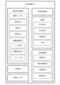
- FIG. 1 is a functional block diagram showing an embodiment of a seasoning liquid supplying device according to the present invention.
- 4 is a schematic diagram showing a supply path of seasoning liquid by the supply device.
- FIG. FIG. 4 is a schematic diagram showing a positional relationship between a temperature sensor and a suction pipe provided in the supply device inside a storage tank.
- FIG. 5A and 5B are schematic diagrams showing the inclination of a shielding plate provided in the supply device.
- 13 is a perspective view showing a state in which a holding portion of the supply device is moved upward.
- FIG. FIG. 4 is a perspective view showing another embodiment of the supply device.
- 5 is a schematic diagram showing an attachment position of a position adjustment unit in a housing of the supply device.
- FIG. FIG. 11 is a perspective view showing still another embodiment of the supply device.
- the following explanation uses a temperature measuring device that measures the temperature of ramen soup stored in a cylinder and heated, and a supplying device that supplies the soup stored in the cylinder from the cylinder to the rice bowl in which the ramen is stored. That is, the temperature measuring device and supplying device are installed in the kitchen of a ramen shop.
- ramen is an example of food and drink in the present invention.
- Ramen soup is an example of seasoning liquid in the present invention.
- the cylinder is an example of a storage tank in which seasoning liquid is stored in the present invention.
- the rice bowl is an example of a container that contains food and drink.
- the seasoning liquid in this invention is not limited to ramen soup.
- FIG. 1 is a functional block diagram showing an embodiment of a seasoning liquid supplying device and a temperature measuring device according to the present invention.
- Supply device 100 (hereinafter referred to as "device 100") is an example of a seasoning liquid supply device according to the present invention.
- Device 100 supplies soup stored in a pot at a specified time and in a specified amount to a rice bowl.
- device 100 supplies soup from the pot to the bowls based on a control signal from a control system (not shown) installed inside the ramen shop.
- a control system (not shown) installed inside the ramen shop.
- the timing at which device 100 supplies soup to the bowls is determined by the control system.
- the control system for example, receives order information from customers and controls the operation of device 100 based on the order information.
- the device 100 includes a temperature measuring device 1, a liquid delivery unit 2, a flow rate sensor 3, a supply control unit 4, a pipe 5, and a heating device 6.
- the temperature measuring device 1 (hereinafter referred to as "device 1") provided in the device 100 is an example of a seasoning liquid temperature measuring device according to the present invention.
- Device 1 measures the temperature of soup stored in a pot and being heated. The measured temperature is used to control the heating of the soup in the pot.
- the liquid delivery unit 2 delivers the soup stored in the pot from the pot to the bowl.
- the liquid delivery unit 2 is a tubing pump.
- Flow sensor 3 measures the flow rate of soup sent from the pot to the bowl.
- Flow sensor 3 is a Coriolis flow meter.
- the flow sensor in the present invention may be an ultrasonic flow meter.
- the supply control unit 4 controls the supply of soup from the pot to the bowl based on the flow rate measured by the flow sensor 3.
- the supply control unit 4 controls the supply of soup from the pot to the bowl by controlling the opening and closing of a valve 54, which will be described later, based on the flow rate measured by the flow sensor 3.
- the supply control unit 4 is realized by a control program that runs on a PLC (Programmable Logic Controller).
- the supply control unit in the present invention is not limited to a control program that runs on a PLC.
- the supply control unit may be anything that can control the opening and closing of the valve 54 described below, and may be realized, for example, by a control program that runs on a microcomputer or FPGA (Field Programmable Gate Array).
- the soup that is supplied from the pot to the bowl passes through the piping 5.
- the piping 5 includes an intake pipe 51, an exhaust pipe 52, a return pipe 53, and a valve 54.
- the suction pipe 51 is a pipe through which the soup in the pot passes as it is sucked up by the liquid delivery unit 2. One end of the suction pipe 51 is placed inside the pot. The other end of the suction pipe 51 is connected to a valve 54. The flow rate of the soup passing through the suction pipe 51 is measured by a flow sensor 3.
- the discharge pipe 52 is a pipe through which the soup that has passed through the valve 54 passes. One end of the discharge pipe 52 is connected to the valve 54. The other end of the discharge pipe 52 is disposed near the bowl. The soup that has passed through the discharge pipe 52 is supplied to the bowl.
- the return pipe 53 is a pipe through which the soup that has passed through the suction pipe 51 but has not passed through the valve 54 passes.
- One end of the return pipe 53 is connected to the valve 54.
- the other end of the return pipe 53 is placed inside the pot.
- the soup that has passed through the return pipe 53 is supplied (returned) to the pot.
- the valve 54 switches the connection between the suction pipe 51 and the exhaust pipe 52 or the return pipe 53. That is, the valve 54 switches the connection between the suction pipe 51 and the exhaust pipe 52, or the connection between the suction pipe 51 and the return pipe 53.
- the valve 54 is a pinch valve.
- the heating device 6 heats the soup stored in the pot.
- the heating device 6 is an induction heating heater.
- the heating device 6 includes a heating unit 61, a heating control unit 62, a memory unit 63, and an operation unit 64.
- the heating unit 61 inductively heats the soup stored in the pot.
- the heating unit 61 has a heating coil that heats the bottom of the pot (made of metal), which is a magnetic body. In other words, the soup stored in the pot is heated by heating the bottom of the pot with the heating coil.
- the heating control unit 62 controls the heating output of the heating unit 61 so that the temperature of the soup stored in the pot converges to a predetermined temperature (target temperature: for example, 95°C) without exceeding the predetermined temperature (upper limit temperature: for example, 100°C). That is, the heating control unit 62 controls the supply of current to the heating coil of the heating unit 61 (PID control). That is, the heating control unit 62 determines the on/off of the supply of current to the heating coil, the current value of the current supplied, and the like.
- the heating control unit 62 is realized by a computer program that runs on a microcomputer. The heating control unit 62 controls the heating output of the heating unit 61 based on the temperature measured by the device 1, the target temperature stored in the memory unit 63, adjustment parameters for PID control, and the like.
- the target temperature is set by the user based on, for example, the boiling point of the soup, the type of soup, the amount of soup stored in the pot, the change in room temperature in the kitchen in which the device 100 is installed, etc.
- the target temperature is lower than the boiling point (upper limit temperature) of the soup.
- the temperature of the soup stored in the pot converges to the target temperature through PID control by the heating control unit 62.
- the manner in which the temperature of the soup stored in the pot converges to the target temperature may be, for example, a manner in which the temperature converges to the target temperature without exceeding the target temperature (so as not to overshoot), or a manner in which the temperature converges to the target temperature without exceeding the upper limit temperature even if the target temperature is exceeded.
- the memory unit 63 stores information necessary for the operation of the heating device 6.
- the information stored in the memory unit 63 includes the target temperature and adjustment parameters for PID control by the heating control unit 62.
- the storage unit in the present invention may be, for example, a portable storage medium such as a hard disk drive (HDD), a solid state drive (SSD), or a flash memory, or other non-temporary storage medium, or a random access memory (RAM) or other temporary storage medium, etc.
- a portable storage medium such as a hard disk drive (HDD), a solid state drive (SSD), or a flash memory, or other non-temporary storage medium, or a random access memory (RAM) or other temporary storage medium, etc.
- the operation unit 64 receives operation information required for the operation of the heating device 6 from the user of the device 100 (a staff member at the ramen shop).
- the user operates the operation unit 64 to operate the device 100. For example, when the user wishes to change the target temperature stored in the memory unit 63, the user inputs the changed target temperature from the operation unit 64.
- the operation unit 64 is configured as a touch panel.
- the device 1 includes a temperature sensor 11, a holding unit 12, a housing 13, a shielding plate 14, and a position adjustment unit 15.
- the temperature sensor 11 is placed inside the pot and measures the temperature of the soup stored in the pot.
- the temperature sensor 11 is a sheathed thermocouple (e.g., a K-type thermocouple or a T-type thermocouple) in which a pair of thermocouple wires is housed in a metal sheath.
- the holding unit 12 holds the temperature sensor 11. Details of the configuration of the holding unit 12 will be described later.
- the housing 13 houses the heating device 6 that heats the soup stored in the pot.
- the shielding plate 14 is placed above the cylinder. Details of the shielding plate 14 will be described later.
- the position adjustment unit 15 makes it possible to adjust the position of the temperature sensor 11 with respect to the pot.
- the position adjustment portion 15 includes a rail portion 16 , a position fixing portion 17 , and a stopper 18 .
- the rail portion 16 (for example, an aluminum frame FSL-L type manufactured by Sugatsune Kogyo Co., Ltd.) moves the holding portion 12 so that the temperature sensor 11 can move back and forth between the inside and outside of the storage tank.
- the position fixing part 17 (for example, a free slide lock FSL-V36 manufactured by Sugatsune Kogyo Co., Ltd.) fixes the position of the holding part 12 relative to the rail part 16.
- the position fixing part 17 includes a slide part that is placed within the rail of the rail part 16, and a restriction operation part that operates the restriction of the movement of the slide part within the rail.
- the restriction operation part When the user operates the restriction operation part to enable the slide part to move within the rail, the position fixing part 17 becomes movable along the rail of the rail part 16.
- the restriction operation part to disable the slide part from moving within the rail the position fixing part 17 becomes unable to move along the rail of the rail part 16.
- the position fixing portion 17 is coupled to the holding portion 12. That is, when the restricting operation portion of the position fixing portion 17 is operated and the position fixing portion 17 moves along the rail of the rail portion 16, the holding portion also moves along the rail of the rail portion 16. As described above, the holding portion 12 holds the temperature sensor 11. That is, when the restricting operation portion of the position fixing portion 17 is operated and the position fixing portion 17 moves along the rail of the rail portion 16, the temperature sensor 11 also moves along the rail of the rail portion 16.
- the stoppers 18 (for example, stopper FSL-S4 manufactured by Sugatsune Kogyo Co., Ltd.) are arranged within the rail of the rail section 16 so that the sliding section of the position fixing section 17 can abut against them.
- the stoppers 18 are arranged on both ends of the rail. In other words, the stoppers 18 define the range of movement of the position fixing section 17 that can move along the rail.
- the direction of movement of the position fixing part 17, which is movable along the rail of the rail part 16, is the vertical direction (the up-down direction on the paper surface of FIG. 3 described later). That is, the stopper 18 arranged at one end (upper end) of the rail determines the upper limit position of the position fixing part 17, and the stopper 18 arranged at the other end (lower end) of the rail determines the lower limit position of the position fixing part 17. In other words, the stopper 18 determines the upper limit and lower limit positions of the temperature sensor 11 and the suction pipe 51 connected to the position fixing part 17. In other words, the user can position the temperature sensor 11 and the suction pipe 51 connected to the position fixing part 17 to a predetermined position in the vertical direction by moving the position fixing part 17 until the position fixing part 17 abuts against the stopper 18.
- the stopper 18 located at the upper end of the rail is the end cap of the rail (for example, end cap FSL-EC manufactured by Sugatsune Kogyo Co., Ltd.).
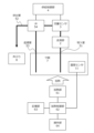
- FIG. 2 is a schematic diagram showing the supply path of soup by the device 100. The figure shows that soup stored in a pot 7 is sucked into the liquid delivery section 2 , passes through a suction pipe 51 , a valve 54 and a discharge pipe 52 , and is supplied to a bowl 8 .
- the figure shows that the flow sensor 3 measures the flow rate of soup passing through the suction pipe 51, and the measurement result (a signal indicating the flow rate) is output to the supply control unit 4.
- the figure shows that the supply control unit 4 controls the opening and closing of the valve 54 based on the flow rate measured by the flow sensor 3.
- the valve 54 When the valve 54 is open, the soup from the suction pipe 51 passes through the discharge pipe 52.
- the valve 54 When the valve 54 is closed, the soup from the suction pipe 51 passes through the return pipe 53 and returns to the pot 7.
- the figure shows that the measurement result (signal indicating the temperature) of the soup stored in the pot 7 measured by the temperature sensor 11 is output to the heating control unit 62.
- the figure shows that the heating control unit 62 controls the heating output of the heating unit 61 based on the measurement result from the temperature sensor 11 and information (upper limit temperature and target temperature) stored in the memory unit 63.
- the figure shows that the heating unit 61 heats the outside of the bottom (bottom surface) of the pot 7, thereby heating the soup inside the pot 7.
- the upper limit temperature is the boiling point of the soup.
- the target temperature is a temperature lower than the upper limit temperature, and is the temperature at which the ramen served in a bowl to the customer has the desired flavor.
- the heating control unit 62 controls the heating output of the heating unit 61 based on the change in the temperature of the soup in the pot 7 measured by the temperature sensor 11, which is stored in the memory unit 63, so that the temperature of the soup in the pot 7 does not exceed the upper limit temperature.
- the temperature sensor 11 measures the temperature at the hottest position in the pot 7.
- the heating control unit 62 heats the soup in the pot 7 so that the soup does not boil and generate air bubbles.
- the flow sensor 3 can measure an accurate flow rate.
- the heating control unit 62 controls the heating output of the heating unit 61 based on the change in the temperature of the soup in the pot 7 measured by the temperature sensor 11 which is stored in the memory unit 63, so that the temperature of the soup in the pot 7 becomes the target temperature. That is, when the temperature measured by the temperature sensor 11 is lower than the target temperature, the heating control unit 62 increases the heating output of the heating unit 61 so that the temperature of the soup in the pot 7 rises.
- the heating control unit 62 reduces the heating output of the heating unit 61 so that the temperature of the soup in the pot 7 drops or the rate of rise slows.
- the heating control unit 62 controls the heating output of the heating unit 61 so that the temperature of the soup in the pot 7 converges to the target temperature without exceeding the upper limit temperature, even if there are factors that cause the temperature of the soup in the pot 7 to fluctuate, such as the air temperature in the kitchen where the pot 7 is located or the replenishment of soup to the pot 7.
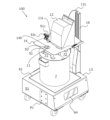
- FIG. 3 is a perspective view of the device 100.
- the figure shows that the cylinder 7 is placed in the heating section 61 of the heating device 6 housed in the housing 13.
- the housing 13 is provided with heat-resistant glass (not shown) (e.g., Fairlight (registered trademark) manufactured by Nippon Electric Glass Co., Ltd.) that covers the surface of the heating section 61.
- the bottom surface of the cylinder 7 is placed on the surface of the heat-resistant glass.
- the figure shows that the shielding plate 14 has a hole 14h that allows soup to be replenished into the pot 7 while the pot 7 is placed on the device 100. That is, the user removes the lid (the lid 71 of the two halves, lid 71 and lid 72) covering the opening of the cylindrical pot 7 from the cylindrical pot 7. The hole 14h is located above a part of the opening of the cylindrical pot 7 from which the lid 71 has been removed. The user then inserts a funnel into hole 14h. The funnel is placed into hole 14h. Next, the user pours the refill soup (stored in the refill pot) into the funnel from above the funnel inserted into the hole 14h. The refill soup poured into the funnel passes through the funnel and the opening of the pot 7, and is supplied to the inside of the pot 7. Next, when the user has completed refilling the soup, he or she covers the opening of the stockpot 7 with the lid 71 and removes the funnel from the hole 14h.
- the lid the lid 71 of the two halves, lid 71 and lid 72
- the shielding plate does not have to have a hole through which the funnel is inserted.
- the user removes the lid 71 from the opening of the stockpot 7 and pours the soup for refilling directly into the inside of the stockpot 7 through the part of the opening of the stockpot 7 that was covered by the lid 71.
- the figure shows that joints 51C and 53C are disposed on the shielding plate 14.
- the joint 51C constitutes a part of the suction pipe 51.
- One end of the suction pipe 51 arranged inside the cylindrical body 7 is connected to the joint 51C.
- One end of a suction pipe (not shown) that is connected to the liquid delivery unit 2 housed in the holding unit 12 is connected to the joint 51C.
- the joint 53C constitutes a part of the return pipe 53.
- One end of the return pipe 53 arranged inside the cylindrical body 7 is connected to the joint 53C.
- One end of a return pipe (not shown) connected to the valve 54 is connected to the joint 53C.
- the figure shows that the signal line 11L is inserted inside the rail portion 16.
- Signal line 11L transmits a signal corresponding to the temperature of the soup stored in pot 7 measured by temperature sensor 11 to heating control unit 62.
- One end of signal line 11L is connected to temperature sensor 11 arranged inside pot 7.
- the other end of signal line 11L is connected to heating control unit 62 housed in housing 13.
- the temperature of the soup stored in pot 7 is measured based on the magnitude of the thermoelectromotive force generated according to the temperature difference (T1-T2) between the temperature (T1) at one end of signal line 11L arranged inside pot 7 and the temperature (T2) at the other end of signal line 11L connected to heating control unit 62.
- the figure shows that a mounting point P1 (an area surrounded by a dashed line in the figure) is disposed on a side surface S1 of the housing 13.
- the mounting location P1 is a location where the rail portion 16 is attached to the housing 13.
- the figure shows that six bolts for attaching the rail portion 16 to the housing 13 are arranged at the mounting location P1 on the side surface S1.
- the housing 13 has two locations where the rail portion 16 is attached.
- the mounting location P1 is the first mounting location in the present invention. The user selects one of the two locations (P1, P2) on the housing 13 as the location where the rail portion 16 is attached, depending on the layout of the kitchen in which the device 100 is installed (including the orientation and shape of the equipment in the kitchen, the movement of the staff in the kitchen, etc.). Note that the figure shows a case where the rail portion 16 is attached to the second mounting location (P2 in FIG. 8) of the housing 13.
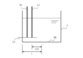
- Figure 4 is a schematic diagram showing the positional relationship between the temperature measuring part of the temperature sensor 11 and the intake port of the intake pipe 51 inside the cylinder 7.
- the figure shows that the height direction (up and down direction on the paper) positions of the bottom ends of the temperature sensor 11 and the suction pipe 51 are aligned at the position indicated by the dashed line L1.
- the temperature sensor 11 measures the temperature near the bottom end of the temperature sensor 11. In other words, the temperature measuring part of the temperature sensor 11 is located at the bottom end of the temperature sensor 11.
- the suction pipe 51 sucks soup from the bottom end of the suction pipe 51. In other words, the suction port of the suction pipe 51 is located at the bottom end of the suction pipe 51.
- the temperature of the soup stored in the pot 7 is higher the closer it is to the bottom surface 7B of the pot 7, which is closer to the heating section 61.
- the temperature sensor 11 measures the temperature of the soup stored in the pot 7 that is close to the temperature of the soup that is sucked in through the suction pipe 51 and supplied to the bowl.
- the vertical positions of the temperature sensor 11 and the suction pipe 51 can be adjusted by the user by operating the position adjustment unit 15. That is, when the soup stored in the pot 7 is being heated so that it can be supplied to the rice bowl 8, the user operates the position fixing unit 17 to move the position fixing unit 17 downward until the position fixing unit 17 abuts against the stopper 18 arranged at the lower end of the rail portion 16, thereby fixing the position of the position fixing unit 17 relative to the rail portion 16.
- the lower end of the temperature sensor 11 and the suction pipe 51 are positioned near the inner surface of the bottom surface 7B of the pot 7 (the inner surface of the pot 7), which is the hottest part inside the pot 7 (for example, 5 mm above the inner surface of the bottom surface 7B).
- the figure shows that the temperature sensor 11 is positioned at the midpoint of the radius r of the bottom surface 7B of the bottomed cylindrical drum 7 (a position r/2 from the center point of the bottom surface 7B).
- the radial position of the bottom surface 7B of the temperature sensor 11 is determined by the position adjustment unit 15, similar to the vertical position of the temperature sensor 11 described above.
- the temperature sensor 11 is attached to the shielding plate 14 so that it is positioned at a predetermined radial position of the bottom surface 7B.
- the midpoint of the radius r of the bottom surface 7B is the hottest position inside the cylinder 7.
- the hottest position inside the cylinder 7 in the radial direction of the bottom surface 7B is determined based on the configuration of the heating unit 61 (such as the arrangement of the coils) and the position where the cylinder 7 is placed on the heating unit 61.
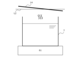
- FIG. 5 is a schematic diagram showing the inclination of the shielding plate 14. As shown in FIG. The figure shows that the shielding plate 14 is disposed at an angle to the horizontal (the direction indicated by the dashed line L2 in the figure). When the temperature sensor 11 is disposed inside the cylinder 7, the shielding plate 14 is disposed above the cylinder 7. A part of the soup stored in the cylinder 7 is heated by the heating section 61 and becomes steam. The steam rises to the top of the cylinder 7 and hits the back surface of the shielding plate 14 (the surface on the lower side of the paper). The steam that hits the shielding plate 14 becomes condensed water. Because the shielding plate 14 is disposed at an angle to the horizontal direction, the condensed water moves along the bottom surface of the shielding plate 14 (to the right on the paper) and falls to the outside of the cylinder 7.
- the shielding plate 14 prevents the condensed water from mixing into the stockpot 7.
- the angle of inclination of the shielding plate 14 relative to the horizontal and the size of the shielding plate 14 are set so that the condensed water does not mix into the stockpot 7.
- the shielding plate 14 also prevents oil from the motor (which drives the agitator described below) housed in the holding part 12 located above the shielding plate 14 from leaking out of the holding part 12 and getting into the inside of the cylindrical barrel 7. In other words, the shielding plate 14 prevents foreign matter from getting into the inside of the cylindrical barrel 7.
- FIG. 6 is a perspective view of the device 100. This figure shows the state in which the holding portion 12 has moved upward along the rail portion 16.
- the user moves the temperature sensor 11, suction pipe 51, return pipe 53, and stirrer SB, which are disposed inside the pot 7, to the outside of the pot 7, and then removes the pot 7, which is enclosed in the housing 13, from the device 100.
- the stirrer SB is disposed inside the pot 7 and includes propeller blades that stir the soup stored in the pot 7. The propeller blades are disposed at the bottom end of the stirrer SB.
- the user operates the position fixing part 17 (not shown) to move the position fixing part 17 upward until the position fixing part 17 abuts against the stopper 18 (not shown) located at the upper end of the rail part 16, thereby fixing the position of the position fixing part 17 relative to the rail part 16.
- the temperature sensor 11, suction pipe 51, return pipe 53, and agitator SB which were located inside the cylindrical body 7, are retracted to the outside of the cylindrical body 7. The user can then easily remove the cylindrical body 7 from the device 100.
- the user installs a new cylinder 7 in the device 100 (places it on the housing 13).
- the user then operates the position fixing part 17 to move the position fixing part 17 downward until the position fixing part 17 abuts against the stopper 18 located at the lower end of the rail part 16, thereby fixing the position of the position fixing part 17 relative to the rail part 16.
- the temperature sensor 11 and the lower end of the suction pipe 51 are positioned at predetermined positions inside the cylinder 7.
- FIG. 7 is a perspective view showing another embodiment of a supply device according to the present invention. This figure shows that the rail portion 16 is attached to the first attachment position (P1, see FIG. 3) on the side surface S1 of the housing 13, as described above.
- Figure 8 is a schematic diagram of the housing 13 in a plan view, showing the mounting position of the rail portion 16 on the housing 13.
- the figure shows that the housing 13 has a first surface S1 and a second surface S2, that the first mounting location P1 is located on the first surface S1, and that the second mounting location P2 is located on the second surface S2.
- the figure shows that the first mounting location P1 and the second mounting location P2 are located at opposing positions across the position of the heating section 61 (heating device 6) in a plan view of the housing. Note that in the figure, the first mounting location P1 and the second mounting location P2 are indicated by black circles for ease of explanation.
- the figure shows that the heating section 61 (heating device 6) is positioned on the housing on an imaginary line L3 that connects the first mounting position P1 and the second mounting position P2.
- FIG. 9 is a perspective view of a liquid seasoning supplying device and a temperature measuring device according to another embodiment of the present invention.
- Device 200 is an example of another embodiment of the seasoning liquid supply device according to the present invention.
- Device 200 differs from device 100 in that holding unit 120 constituting the temperature measuring device is different from holding unit 12 constituting device 1.
- the figure shows that the holding part 120 that holds the temperature sensor 11 is connected to the position fixing part 17.
- the figure shows that the holding part 120 is plate-shaped, unlike the holding part 12.
- the holding part 120 holds only the temperature sensor 11.
- the holding part 120 does not hold the joints that form part of the piping (joints 51C, 53C in FIG. 3) or the agitator (agitator SB in FIG. 6).
- the seasoning liquid temperature measuring device of the present invention only needs to include a holding section that holds the temperature sensor 11, allowing the temperature sensor 11 to move back and forth between the inside and outside of the pot 7, and a position adjustment section that allows the position of the temperature sensor 11 to be adjusted relative to the pot 7.
- the holding section may or may not hold other components (for example, the aforementioned joint or agitator) in addition to the temperature sensor 11.
- the position adjustment unit 15 can position the temperature measuring portion of the temperature sensor 11 at the hottest position in the cylinder 7.
- the temperature measuring portion of the temperature sensor 11 is positioned at a desired position by the user moving the position fixing unit 17 downward until the position fixing unit 17 abuts against the stopper 18. In other words, the positioning of the temperature sensor 11 is easily achieved.
- the heating control unit 62 realizes heating of the soup in the pot 7 so that the temperature of the soup in the pot 7 converges to the target temperature without exceeding the upper limit temperature.
- the flow rate sensor 3 can measure the flow rate accurately.
- the temperature measuring portion of the temperature sensor 11 is disposed at the same height as the suction port of the suction pipe 51 within the pot 7. That is, the temperature sensor 11 measures a temperature of the soup stored in the pot 7 that is close to the temperature of the soup that is sucked in through the suction pipe 51 and supplied to the bowl. Therefore, the device 1 and devices 100 and 200 can supply the soup stored and heated in the pot 7 to the bowl at an appropriate temperature and in an appropriate amount.
- the temperature sensor 11 and other sensors placed inside the cylinder 7 can be positioned to the desired position, i.e., a position where the temperature sensor 11 and other sensors do not get in the way when the cylinder 7 is replaced, by the user moving the position fixing portion 17 upward until the position fixing portion 17 abuts against the stopper 18. Therefore, the device 1 and the devices 100 and 200 facilitate use by the user, such as by replacing the drum 7 and cleaning the device 1 and the devices 100 and 200.
- the temperature sensor 11 is disposed inside the pot 7, not outside the pot 7. By disposing the temperature sensor 11 inside the pot 7, the temperature sensor 11 can directly measure the temperature of the soup stored inside the pot 7.
- the temperature measured by temperature sensor 11 will be different from the temperature of the soup stored inside cylinder 7.
- the responsiveness of the temperature sensor 11 arranged inside cylinder 7 in measuring the soup temperature is better than the responsiveness of the temperature sensor 11 arranged outside cylinder 7 in measuring the soup temperature.
- the accuracy of the soup temperature control by heating control unit 62 using temperature sensor 11 arranged inside cylinder 7 is higher than the accuracy of the soup temperature control by heating control unit 62 using temperature sensor 11 arranged outside cylinder 7.
- the seasoning liquid temperature measuring device is A device (e.g., device 100, 200) for measuring the temperature of a seasoning liquid (e.g., ramen soup) stored in a storage tank (e.g., a cylinder 7) and heated, A temperature sensor (e.g., temperature sensor 11) disposed inside the storage tank to measure the temperature of the seasoning liquid stored in the storage tank; A holder (e.g., holder 12/120) for holding the temperature sensor; A position adjustment unit (e.g., a position adjustment unit 15) that adjusts the position of the temperature sensor relative to the storage tank; Is there, It is characterized by:
- the position adjustment unit is A rail portion (e.g., rail portion 16) that moves the holding portion so that the temperature sensor can advance and retreat between the inside and the outside of the storage tank; A position fixing portion (e.g., a position fixing portion 17) that fixes the position of the holding portion relative to the rail portion;
- the present invention may also include:
- the rail portion is A stopper (e.g., stopper 18) for positioning the temperature sensor relative to the reservoir;
- the present invention may also include:
- the seasoning liquid temperature measuring device is A housing (e.g., housing 13) to which the rail portion is attached; and the housing includes an attachment portion to which the rail portion is attached,
- the attachment point is A first attachment point (e.g., a first attachment point P1); a second attachment point (e.g., second attachment point P2); It may include.
- the seasoning liquid temperature measuring device is The housing accommodates a heating device (e.g., heating device 6) that heats the seasoning liquid inside the storage tank,
- a heating device e.g., heating device 6
- the first mounting location and the second mounting location may be located at opposing positions (e.g., on the first surface S1 and the second surface S2) across the position of the heating device in a plan view of the housing.
- the arrangement position of the heating device in the housing may be on a virtual line (e.g., a virtual line L3) connecting the first attachment point and the second attachment point.
- a virtual line e.g., a virtual line L3 connecting the first attachment point and the second attachment point.
- the seasoning liquid temperature measuring device is A shielding plate (e.g., shielding plate 14) disposed above the storage tank; and When the temperature sensor is disposed inside the storage tank, the shielding plate may be disposed obliquely relative to the horizontal.
- shielding plate e.g., shielding plate 14
- the temperature sensor When the temperature sensor is disposed within the interior of the reservoir, The holding portion is disposed above the shielding plate, The temperature sensor may be disposed below the shielding plate.
- the shielding plate is a hole (e.g., hole 14h) through which a funnel is disposed, through which a replenishment liquid is passed to replenish the reservoir;
- the present invention may also include:
- the seasoning liquid supply device comprises: A device for supplying a seasoning liquid (e.g., soup) contained in food or drink (e.g., ramen) to a container (e.g., a bowl 8) in which the food or drink is contained, A liquid delivery unit (e.g., liquid delivery unit 2) that delivers the liquid seasoning from a storage tank (e.g., a cylinder 7) in which the liquid seasoning is stored to the container; A flow rate sensor (e.g., flow rate sensor 3) that measures the flow rate of the seasoning sent from the storage tank to the container; A supply control unit (e.g., a supply control unit 4) that controls the supply of the seasoning liquid from the storage tank to the container based on the flow rate measured by the flow rate sensor; A heating device (for example, a heating device 6) that heats the seasoning liquid stored in the storage tank; A temperature measuring device (e.g., device 1) for measuring the temperature of the seasoning liquid stored in the storage tank; and The temperature measuring
- the heating device includes: A heating unit (for example, heating unit 61) that heats the seasoning liquid stored in the storage tank; A heating control unit (e.g., a heating control unit 62) that controls the heating output of the heating unit; Equipped with The heating control unit may control the heating output based on a change in the temperature measured by the temperature measuring device.
- a heating unit for example, heating unit 61
- a heating control unit e.g., a heating control unit 62
- the heating control unit may control the heating output based on a change in the temperature measured by the temperature measuring device.
- the heating device includes: A memory unit (e.g., memory unit 63) that stores a target temperature (e.g., 95°C) of the seasoning liquid stored in the storage tank; Equipped with The target temperature is lower than the boiling point of the seasoning liquid,
- the heating control unit may control the heating output so that the temperature measured by the temperature measuring device converges to the target temperature.
- the heating unit heats the outside of the bottom of the storage tank (for example, the bottom surface 7B of the cylinder 7), A height position of a temperature measuring portion of the temperature sensor within the interior of the storage tank may be near the inside of the bottom of the storage tank.
- a pipe (for example, a pipe 5) through which the seasoning liquid stored in the storage tank passes; and One end of the pipe is disposed inside the storage tank, A height position of the one end within the interior may be substantially equal to a height position of the temperature sensor within the interior.
- the piping includes: A suction pipe (e.g., suction pipe 51) arranged on the storage tank side; A discharge pipe (e.g., discharge pipe 52) disposed on the container side; a valve (e.g., valve 54) disposed between the intake pipe and the exhaust pipe; Equipped with The supply control unit may control the supply of the liquid seasoning from the storage tank to the container by controlling opening and closing of the valve.
- a suction pipe e.g., suction pipe 51
- a discharge pipe e.g., discharge pipe 52
- a valve e.g., valve 54
Landscapes
- Physics & Mathematics (AREA)
- General Physics & Mathematics (AREA)
- Commercial Cooking Devices (AREA)
- Cookers (AREA)
Abstract
Description
本発明は、調味液の温度測定装置と、調味液の供給装置と、に関する。 The present invention relates to a seasoning liquid temperature measuring device and a seasoning liquid supply device.
飲食物の調理や配膳などを行う調理ロボットは、労働人口の減少を背景にして、飲食店などにおいて、導入が進められている。本願の出願人は、ラーメンなどのスープを、スープが貯留されている寸胴から、来店客に配膳される丼ぶりに供給する装置に関する発明をした(特許文献1参照)。 Cooking robots that cook and serve food and drink are being increasingly introduced into restaurants and other establishments amid a decline in the working population. The applicant of this application has invented a device that dispenses soup from ramen and other dishes from a stockpot in which the soup is stored into bowls that are then served to customers (see Patent Document 1).
ラーメンは、麺などの具材とスープなどの調味液とで構成される。ラーメンの美味しさは、調味液の温度と量とに依存する。そのため、調味液が貯留されている寸胴から丼ぶりに調味液を供給する装置は、温度センサや流量センサなどを用いて、丼ぶりに供給される調味液の温度と量とを高精度に制御する必要がある。ここで、寸胴の内部の調味液が加熱されて気泡が発生してしまうと、流量センサによる流量の計測結果に狂いが生じてしまう。その結果、丼ぶりに供給される調味液の温度と量とが目標値から外れてしまい、ラーメンの味は、所望の味とはならない。 Ramen consists of ingredients such as noodles and seasoning such as soup. The deliciousness of ramen depends on the temperature and amount of seasoning. For this reason, a device that supplies seasoning from a pot in which the seasoning is stored to a bowl must use a temperature sensor, flow sensor, etc. to control the temperature and amount of seasoning supplied to the bowl with high precision. Here, if the seasoning inside the pot becomes heated and air bubbles are generated, the flow rate measurement by the flow sensor will be distorted. As a result, the temperature and amount of seasoning supplied to the bowl will deviate from the target values, and the ramen will not taste as desired.
これまでにも、温度センサを備えた加熱調理器に関する発明は、提案されている(例えば、特許文献2参照)。 Inventions relating to cooking appliances equipped with temperature sensors have been proposed in the past (see, for example, Patent Document 2).
本発明は、貯留槽に貯留されて加熱されている調味液を、適温かつ適量で、飲食物を収容する容器に供給できる、調味液の温度測定装置と供給装置とを提供することを目的とする。 The present invention aims to provide a seasoning liquid temperature measuring device and supplying device that can supply a seasoning liquid stored in a storage tank and heated at an appropriate temperature and in an appropriate amount to a container that contains food or drink.
本発明に係る調味液の温度測定装置は、貯留槽に貯留されて加熱される調味液の温度を測定する装置であって、貯留槽の内部に配置されて、貯留槽に貯留されている調味液の温度を測定する温度センサと、温度センサを保持する保持部と、貯留槽に対する温度センサの位置を調整可能にする位置調整部と、を有してなる、ことを特徴とする。 The seasoning liquid temperature measuring device of the present invention is a device for measuring the temperature of seasoning liquid stored in a storage tank and heated, and is characterized in that it comprises a temperature sensor that is disposed inside the storage tank and measures the temperature of the seasoning liquid stored in the storage tank, a holding unit that holds the temperature sensor, and a position adjustment unit that makes it possible to adjust the position of the temperature sensor relative to the storage tank.
本発明は、貯留槽に貯留されて加熱されている調味液を、適温かつ適量で、飲食物を収容する容器に供給できる。 The present invention can supply liquid seasoning stored in a storage tank and heated at an appropriate temperature and in an appropriate amount to a container that holds food or drink.
本発明に係る、調味液の温度測定装置と、調味液の供給装置と、の実施の形態は、以下に図面と共に説明される。 Embodiments of the seasoning liquid temperature measuring device and seasoning liquid supply device according to the present invention are described below with reference to the drawings.
以下の説明は、寸胴に貯留されて加熱されているラーメンのスープの温度を測定する温度測定装置と、寸胴に貯留されているスープを寸胴からラーメンが収容される丼ぶりに供給する供給装置と、が用いられる。すなわち、温度測定装置と供給装置とは、ラーメン店の店内の厨房に設置される。ここで、ラーメンは、本発明における飲食物の例である。ラーメンのスープは、本発明における調味液の例である。寸胴は、本発明における調味液が貯留される貯留槽の例である。丼ぶりは、飲食物を収容する容器の例である。 The following explanation uses a temperature measuring device that measures the temperature of ramen soup stored in a cylinder and heated, and a supplying device that supplies the soup stored in the cylinder from the cylinder to the rice bowl in which the ramen is stored. That is, the temperature measuring device and supplying device are installed in the kitchen of a ramen shop. Here, ramen is an example of food and drink in the present invention. Ramen soup is an example of seasoning liquid in the present invention. The cylinder is an example of a storage tank in which seasoning liquid is stored in the present invention. The rice bowl is an example of a container that contains food and drink.
なお、本発明における調味液は、ラーメンのスープに限定されない。 The seasoning liquid in this invention is not limited to ramen soup.
●調味液の供給装置と温度測定装置の構成(1)●
図1は、本発明に係る調味液の供給装置と温度測定装置との実施の形態を示す機能ブロック図である。
●Configuration of seasoning liquid supply device and temperature measurement device (1)●
FIG. 1 is a functional block diagram showing an embodiment of a seasoning liquid supplying device and a temperature measuring device according to the present invention.
供給装置100(以下「装置100」という。)は、本発明に係る調味液の供給装置の例である。装置100は、寸胴に貯留されているスープを、所定のタイミングで、所定の量だけ、丼ぶりに供給する。
Supply device 100 (hereinafter referred to as "
ここで、装置100は、ラーメン店の店内に設置されている制御システム(不図示)からの制御信号に基づいて、スープを寸胴から丼ぶりに供給する。すなわち、装置100がスープを丼ぶりに供給するタイミングは、制御システムに決定される。制御システムは、例えば、来店客からの注文情報を受け付けて、同注文情報に基づいて、装置100の動作を制御する。
Here,
装置100は、温度測定装置1と、送液部2と、流量センサ3と、供給制御部4と、配管5と、加熱装置6と、を備える。
The
装置100が備える温度測定装置1(以下「装置1」という。)は、本発明に係る調味液の温度測定装置の例である。
The temperature measuring device 1 (hereinafter referred to as "device 1") provided in the
装置1は、寸胴に貯留されて加熱されているスープの温度を測定する。測定された温度は、寸胴内のスープの加熱制御に用いられる。 Device 1 measures the temperature of soup stored in a pot and being heated. The measured temperature is used to control the heating of the soup in the pot.
送液部2は、寸胴に貯留されているスープを、寸胴から丼ぶりに送る。送液部2は、チュービングポンプである。
The
流量センサ3は、寸胴から丼ぶりに送られるスープの流量を計測する。流量センサ3は、コリオリ式流量計である。
なお、本発明における流量センサは、超音波流量計でもよい。 The flow sensor in the present invention may be an ultrasonic flow meter.
供給制御部4は、流量センサ3により計測された流量に基づいて、スープの寸胴から丼ぶりへの供給を制御する。供給制御部4は、流量センサ3により計測された流量に基づいて、後述される弁54の開閉を制御することで、スープの寸胴から丼ぶりへの供給を制御する。供給制御部4は、PLC(Programmable Logic Controller)で動作する制御プログラムにより実現される。
The
なお、本発明における供給制御部は、PLCで動作する制御プログラムに限られない。すなわち、供給制御部は、後述される弁54の開閉の制御を実現できるものであればよく、例えば、マイクロコンピュータ(マイコン)やFPGA (Field Programmable Gate Array)で動作する制御プログラムにより実現されてもよい。
The supply control unit in the present invention is not limited to a control program that runs on a PLC. In other words, the supply control unit may be anything that can control the opening and closing of the
配管5は、寸胴から丼ぶりに供給されるスープが通過する。配管5は、吸入管51と、排出管52と、返還管53と、弁54と、を備える。
The soup that is supplied from the pot to the bowl passes through the piping 5. The piping 5 includes an
吸入管51は、送液部2により吸い上げられる寸胴内のスープが通過する管である。吸入管51の一端は、寸胴内に配置される。吸入管51の他端は、弁54に接続される。吸入管51を通過するスープの流量は、流量センサ3により計測される。
The
排出管52は、弁54を通過したスープが通過する管である。排出管52の一端は、弁54に接続される。排出管52の他端は、丼ぶりの近傍に配置される。排出管52を通過したスープは、丼ぶりに供給される。
The
返還管53は、吸入管51を通過したスープのうち、弁54を通過しないスープが通過する管である。返還管53の一端は、弁54に接続する。返還管53の他端は、寸胴内に配置される。返還管53を通過したスープは、寸胴に供給される(戻される)。
The
弁54は、吸入管51と、排出管52または返還管53と、の間の接続を切替える。すなわち、弁54は、吸入管51と排出管52との接続、または、吸入管51と返還管53との接続、を切替える。弁54は、ピンチバルブである。
The
加熱装置6は、寸胴に貯留されているスープを加熱する。加熱装置6は、IH(Induction Heating)ヒータである。加熱装置6は、加熱部61と、加熱制御部62と、記憶部63と、操作部64と、を備える。
The heating device 6 heats the soup stored in the pot. The heating device 6 is an induction heating heater. The heating device 6 includes a
加熱部61は、寸胴に貯留されているスープを誘導加熱する。加熱部61は、磁性体である寸胴(金属製)の底面を加熱する加熱コイルを備える。すなわち、寸胴の底面が加熱コイルにより加熱されることで、寸胴に貯留されているスープは、加熱される。
The
加熱制御部62は、寸胴に貯留されているスープの温度が、所定の温度(上限温度:例えば100℃)を超過することなく、所定の温度(目標温度:例えば95℃)に収束するように、加熱部61の加熱出力を制御する。すなわち、加熱制御部62は、加熱部61の加熱コイルへの電流の供給を制御(PID制御)する。つまり、加熱制御部62は、加熱コイルへの電流の供給のオン・オフや、供給される電流の電流値、などを決定する。加熱制御部62は、マイクロコンピュータで動作するコンピュータプログラムにより実現される。加熱制御部62は、装置1に測定された温度や、記憶部63に記憶されている目標温度や、PID制御の調整パラメータなどに基づいて、加熱部61の加熱出力を制御する。
The
ここで、目標温度は、例えば、スープの沸点や、スープの種類や、寸胴に貯留されているスープの量や、装置100が設置される厨房内の室温の推移、などに基づいて、ユーザにより設定される。目標温度は、スープの沸点(上限温度)よりも低い。
Here, the target temperature is set by the user based on, for example, the boiling point of the soup, the type of soup, the amount of soup stored in the pot, the change in room temperature in the kitchen in which the
また、寸胴に貯留されているスープの温度は、加熱制御部62によるPID制御により、目標温度に収束する。寸胴に貯留されているスープの温度が目標温度に収束する態様は、例えば、目標温度を超えないように(いわゆるオーバーシュートしないように)目標温度に収束する態様や、たとえ目標温度を超えたとしても上限温度を超えないように目標温度に収束する態様である。
The temperature of the soup stored in the pot converges to the target temperature through PID control by the
記憶部63は、加熱装置6の動作に必要な情報を記憶する。記憶部63に記憶される情報は、目標温度と、加熱制御部62によるPID制御の調整パラメータと、を含む。
The
なお、本発明における記憶部は、例えば、HDD(Hard Disk Drive)、SSD(Solid State Drive)、フラッシュメモリなどの可搬記憶媒体その他の非一時的な記録媒体や、RAM(Random Access Memory)その他の一時的な記録媒体、などである。 The storage unit in the present invention may be, for example, a portable storage medium such as a hard disk drive (HDD), a solid state drive (SSD), or a flash memory, or other non-temporary storage medium, or a random access memory (RAM) or other temporary storage medium, etc.
操作部64は、加熱装置6の動作に必要な操作情報を、装置100のユーザ(ラーメン店の店員)から受け付ける。ユーザは、操作部64を操作して、装置100を動作させる。ユーザは、例えば、記憶部63に記憶されている目標温度を変更したいとき、操作部64から変更後の目標温度を入力する。操作部64は、タッチパネルで構成される。
The
●調味液の温度測定装置の構成 ●Configuration of seasoning liquid temperature measuring device
装置1は、温度センサ11と、保持部12と、筐体13と、遮蔽板14と、位置調整部15と、を備える。
The device 1 includes a
温度センサ11は、寸胴の内部に配置されて、寸胴に貯留されているスープの温度を測定する。温度センサ11は、金属シース内に一対の熱電対線が収容されたシース熱電対(例えば、K型熱電対やT型熱電対)である。
The
保持部12は、温度センサ11を保持する。保持部12の構成の詳細は、後述される。
The holding
筐体13は、寸胴に貯留されているスープを加熱する加熱装置6を収容する。
The
遮蔽板14は、寸胴の上方に配置される。遮蔽板14の詳細は、後述される。
The shielding
位置調整部15は、寸胴に対する温度センサ11の位置を調整可能にする。
位置調整部15は、レール部16と、位置固定部17と、ストッパ18と、を備える。
The position adjustment unit 15 makes it possible to adjust the position of the
The position adjustment portion 15 includes a
レール部16(例えば、スガツネ工業株式会社製のアルミフレームFSL-L型)は、温度センサ11が貯留槽の内部と外部との間で進退可能となるように、保持部12を移動させる。
The rail portion 16 (for example, an aluminum frame FSL-L type manufactured by Sugatsune Kogyo Co., Ltd.) moves the holding
位置固定部17(例えば、スガツネ工業株式会社製のフリースライドロックFSL-V36)は、レール部16に対する保持部12の位置を固定する。位置固定部17は、レール部16のレール内に配置されるスライド部と、スライド部のレール内での移動の規制を操作する規制操作部とを備える。ユーザが規制操作部を操作して、スライド部のレール内での移動が可能となると、位置固定部17は、レール部16のレールに沿って移動可能となる。ユーザが規制操作部を操作して、スライド部のレール内での移動が不可能となると、位置固定部17は、レール部16のレールに沿って移動不可能となる。
The position fixing part 17 (for example, a free slide lock FSL-V36 manufactured by Sugatsune Kogyo Co., Ltd.) fixes the position of the holding
ここで、位置固定部17は、保持部12と連結する。すなわち、位置固定部17の規制操作部が操作されて、位置固定部17がレール部16のレールに沿って移動すると、保持部もレール部16のレールに沿って移動する。
また、前述のとおり、保持部12は、温度センサ11を保持する。すなわち、位置固定部17の規制操作部が操作されて、位置固定部17がレール部16のレールに沿って移動すると、温度センサ11もレール部16のレールに沿って移動する。
Here, the
As described above, the holding
ストッパ18(例えば、スガツネ工業株式会社製のストッパFSL-S4)は、位置固定部17のスライド部が当接可能となるように、レール部16のレール内に配置される。ストッパ18は、レールの両端それぞれに配置される。すなわち、ストッパ18は、レールに沿って移動可能な位置固定部17の移動範囲を規定する。
The stoppers 18 (for example, stopper FSL-S4 manufactured by Sugatsune Kogyo Co., Ltd.) are arranged within the rail of the
ここで、レール部16のレールに沿って移動可能な位置固定部17の移動方向は、垂直方向(後述される図3の紙面上下方向)である。すなわち、レールの一端(上端)に配置されたストッパ18は、位置固定部17の上限位置を規定して、レールの他端(下端)に配置されたストッパ18は、位置固定部17の下限位置を規定する。つまり、ストッパ18は、位置固定部17に連結する温度センサ11や吸入管51の上限位置と下限位置とを規定する。換言すれば、ユーザは、位置固定部17がストッパ18に当接するまで位置固定部17を移動させることで、位置固定部17に連結する温度センサ11や吸入管51を、垂直方向の所定の位置に位置決めできる。
Here, the direction of movement of the
なお、以下の説明において、レールの上端に配置されたストッパ18は、レールのエンドキャップ(例えば、スガツネ工業株式会社製のエンドキャップFSL-EC)である。
In the following description, the
●調味液の供給装置の供給経路●
図2は、装置100によるスープの供給経路を示す模式図である。
同図は、寸胴7に貯留されているスープが、送液部2に吸引されて、吸入管51と弁54と排出管52とを通過して、丼ぶり8に供給されることを示す。
●Supply path for seasoning liquid supply device●
FIG. 2 is a schematic diagram showing the supply path of soup by the
The figure shows that soup stored in a
同図は、流量センサ3が吸引管51を通過するスープの流量を計測して、計測結果(流量を示す信号)が供給制御部4に出力されることを示す。同図は、供給制御部4が、流量センサ3に計測された流量に基づいて、弁54の開閉を制御することを示す。弁54が開くと、吸入管51からのスープは、排出管52を通過する。弁54が閉じると、吸入管51からのスープは、返還管53を通過して、寸胴7に戻る。
The figure shows that the
同図は、温度センサ11に測定された寸胴7に貯留されているスープの温度の測定結果(温度を示す信号)が加熱制御部62に出力されることを示す。同図は、加熱制御部62が、温度センサ11からの測定結果や、記憶部63に記憶されている情報(上限温度や目標温度)などに基づいて、加熱部61の加熱出力を制御することを示す。同図は、加熱部61が寸胴7の底部(底面)の外側を加熱して、寸胴7の内部のスープを加熱することを示す。
The figure shows that the measurement result (signal indicating the temperature) of the soup stored in the
ここで、上限温度は、スープの沸点である。目標温度は、上限温度よりも低い温度であり、丼ぶりに収容されて来店客に提供されるラーメンが所望の味となる温度である。 Here, the upper limit temperature is the boiling point of the soup. The target temperature is a temperature lower than the upper limit temperature, and is the temperature at which the ramen served in a bowl to the customer has the desired flavor.
加熱制御部62は、記憶部63に記憶されている温度センサ11に測定された寸胴7内のスープの温度の推移に基づいて、寸胴7内のスープの温度が上限温度を超過しないように、加熱部61の加熱出力を制御する。ここで、後述のとおり、温度センサ11は、寸胴7内で最も高温となる位置の温度を測定する。すなわち、加熱制御部62は、寸胴7内のスープが沸騰して気泡が発生することのないように、寸胴7内のスープの加熱を実現する。その結果、流量センサ3は、正確な流量を計測できる。
The
加熱制御部62は、記憶部63に記憶されている温度センサ11に測定された寸胴7内のスープの温度の推移に基づいて、寸胴7内のスープの温度が目標温度になるように、加熱部61の加熱出力を制御する。
すなわち、加熱制御部62は、温度センサ11に測定された温度が目標温度よりも低いとき、寸胴7内のスープの温度が上昇するように、加熱部61の加熱出力を上げる。
一方、加熱制御部62は、温度センサ11により測定された温度が目標温度よりも高いとき、あるいは、現在の加熱部61の加熱出力で加熱を継続すると温度センサ11により測定される温度が目標温度よりも高くなると予想されるとき、寸胴7内のスープの温度が下降、あるいは、上昇の速度が遅れるように、加熱部61の加熱出力を下げる。
The
That is, when the temperature measured by the
On the other hand, when the temperature measured by the
このように、加熱制御部62は、寸胴7が配置された厨房内の気温や寸胴7へのスープの補給など、寸胴7内のスープの温度を変動させる要因があったとしても、寸胴7内のスープの温度が上限温度を超過することなく、目標温度に収束するように、加熱部61の加熱出力を制御する。
In this way, the
●調味液の供給装置の使用例●
図3は、装置100の斜視図である。
●Example of use of seasoning liquid supply device●
FIG. 3 is a perspective view of the
同図は、筐体13に収容されている加熱装置6の加熱部61に、寸胴7が配置されていることを示す。筐体13は、加熱部61の表面を覆う不図示の耐熱ガラス(例えば、日本電気硝子株式会社製のフェアライト(登録商標))を備える。寸胴7の底面は、耐熱ガラスの表面に載置される。
The figure shows that the
同図は、遮蔽板14が孔14hを備えることを示す。孔14hは、寸胴7を装置100に載置したままで、補給用のスープを寸胴7に補給可能とする孔である。
すなわち、ユーザは、寸胴7の開口を覆う蓋(2分割された蓋71と蓋72とのうち、蓋71)を寸胴7から取り外す。孔14hは、蓋71が取り外された寸胴7の開口の一部の上方に位置する。
次いで、ユーザは、孔14hに漏斗を挿入する。漏斗は、孔14hに配置される。
次いで、ユーザは、孔14hに挿入された漏斗の上方から、補給用のスープ(補給用の寸胴に貯留されている)を漏斗に流し込む。漏斗に流し込まれた補給用のスープは、漏斗と寸胴7の開口とを通過して、寸胴7の内部に供給される。
次いで、ユーザは、スープの補給が完了すると、寸胴7の開口を蓋71で覆い、漏斗を孔14hから取り外す。
The figure shows that the shielding
That is, the user removes the lid (the
The user then inserts a funnel into
Next, the user pours the refill soup (stored in the refill pot) into the funnel from above the funnel inserted into the
Next, when the user has completed refilling the soup, he or she covers the opening of the
なお、本発明において、遮蔽板は、漏斗が挿入される孔を備えていなくてもよい。この場合、例えば、ユーザは、蓋71を寸胴7の開口から取り外して、補給用のスープを、蓋71で覆われていた寸胴7の開口の一部から、寸胴7の内部に、直接、流し込む。
In the present invention, the shielding plate does not have to have a hole through which the funnel is inserted. In this case, for example, the user removes the
同図は、継手51Cと継手53Cとが遮蔽板14に配置されていることを示す。
継手51Cは、吸入管51の一部を構成する。寸胴7の内部に配置された吸入管51の一端は、継手51Cに接続する。保持部12に収容されている送液部2に連結する吸入管(不図示)の一端は、継手51Cに接続する。
継手53Cは、返還管53の一部を構成する。寸胴7の内部に配置された返還管53の一端は、継手53Cに接続する。弁54に接続されている返還管(不図示)の一端は、継手53Cに接続する。
The figure shows that joints 51C and 53C are disposed on the shielding
The joint 51C constitutes a part of the
The joint 53C constitutes a part of the
同図は、信号線11Lがレール部16の内部に挿通されていることを示す。
信号線11Lは、温度センサ11に測定された寸胴7に貯留されているスープの温度に応じた信号を、加熱制御部62に送信する。信号線11Lの一端は、寸胴7の内部に配置されている温度センサ11に接続する。信号線11Lの他端は、筐体13に収容されている加熱制御部62に接続する。すなわち、寸胴7の内部に貯留されたスープの温度は、寸胴7の内部に配置された信号線11Lの一端側の温度(T1)と、加熱制御部62に接続されている信号線11Lの他端側の温度(T2)と、の温度差(T1-T2)に応じて生ずる熱起電力の大きさに基づいて、測定される。
The figure shows that the
同図は、筐体13の側面S1に取付箇所P1(図中の破線で囲まれた領域)が配置されていることを示す。
取付箇所P1は、レール部16が筐体13に取り付けられる箇所である。同図は、レール部16を筐体13に取り付けるボルト6個が、側面S1の取付箇所P1に配置されていることを示す。筐体13は、レール部16が取り付けられる箇所として、2箇所を備える。取付箇所P1は、本発明における第1取付箇所である。ユーザは、装置100が設置される厨房のレイアウト(厨房内の設備の向きや形状、厨房内の店員の動線、など含む)などに応じて、筐体13の2箇所(P1,P2)のいずれか一方を、レール部16が取り付けられる箇所として選択する。なお、同図は、レール部16が筐体13の第2取付箇所(図8のP2)に取り付けられた場合を示す。
The figure shows that a mounting point P1 (an area surrounded by a dashed line in the figure) is disposed on a side surface S1 of the
The mounting location P1 is a location where the
図4は、温度センサ11の測温部と、吸入管51の吸入口と、の寸胴7の内部における位置関係を示す模式図である。
Figure 4 is a schematic diagram showing the positional relationship between the temperature measuring part of the
同図は、温度センサ11と吸入管51それぞれの下端の高さ方向(紙面上下方向)の位置が、破線L1で示される位置で一致していることを示す。温度センサ11は、温度センサ11の下端の近傍で測温する。つまり、温度センサ11の測温部は、温度センサ11の下端に配置される。吸入管51は、吸入管51の下端からスープを吸引する。つまり、吸入管51の吸入口は、吸入管51の下端に配置される。
The figure shows that the height direction (up and down direction on the paper) positions of the bottom ends of the
寸胴7に貯留されているスープの温度は、加熱部61に近い寸胴7の底面7Bに近いスープほど高温である。すなわち、温度センサ11は、寸胴7に貯留されているスープのうち、吸入管51から吸引されて丼ぶりに供給されるスープの温度に近い温度を測定する。
The temperature of the soup stored in the
ここで、前述のとおり、温度センサ11や吸入管51の垂直方向(図3の紙面上下方向)の位置は、ユーザによる位置調整部15の操作により、位置決め可能である。すなわち、ユーザは、丼ぶり8に供給できるように寸胴7に貯留されているスープが加熱されているとき、位置固定部17がレール部16の下端に配置されたストッパ18に当接するまで、位置固定部17を操作して、位置固定部17を下方に移動させて、レール部16に対する位置固定部17の位置を固定しておく。その結果、温度センサ11や吸入管51の下端は、寸胴7の内部で最も高温になる寸胴7の底面7Bの内面(寸胴7の内側の面)の近傍(例えば、底面7Bの内面から5mm上方)に位置決めされる。
As mentioned above, the vertical positions of the
同図は、温度センサ11が有底円筒状の寸胴7の底面7Bの半径rの中間の位置(底面7Bの中心点からr/2の位置)に配置されていることを示す。温度センサ11の底面7Bの半径方向の位置は、前述の温度センサ11の垂直方向の位置と同様、位置調整部15により位置決めされる。換言すれば、温度センサ11は、底面7Bの半径方向の所定の位置に位置決めされるように、遮蔽板14に取り付けられている。
The figure shows that the
ここで、底面7Bの半径rの中間の位置は、寸胴7の内部で最も高温になる位置である。底面7Bの半径方向における、寸胴7の内部で最も高温になる位置は、加熱部61の構成(コイルの配置など)や、寸胴7の加熱部61への載置位置などに基づいて、決まる。
Here, the midpoint of the radius r of the
図5は、遮蔽板14の傾きを示す模式図である。
同図は、遮蔽板14が水平(図中の破線L2が示す方向)に対して斜めに配置されることを示す。遮蔽板14は、温度センサ11が寸胴7の内部に配置されているとき、寸胴7の上方に配置される。寸胴7に貯留されているスープの一部は、加熱部61に加熱されて蒸気となる。蒸気は、寸胴7の上方に昇り、遮蔽板14の裏面(紙面下側の面)に当たる。遮蔽板14に当たった蒸気は、結露水となる。結露水は、遮蔽板14が水平方向に対して斜めに配置されているため、遮蔽板14の下面に沿って(紙面右方向に)移動して、寸胴7の外側に落下する。
FIG. 5 is a schematic diagram showing the inclination of the shielding
The figure shows that the shielding
このように、遮蔽板14は、寸胴7のスープの蒸気が遮蔽板14に当たって結露したとき、その結露水が寸胴7に混入させない。遮蔽板14の水平に対する傾きの角度や、遮蔽板14の大きさなどは、同結露水が寸胴7に混入しないように設定される。
In this way, when the steam from the soup in the
なお、遮蔽板14は、遮蔽板14の上方に配置される保持部12に収容されているモータ(後述の攪拌器を駆動させる)のオイルが保持部12から漏れ出て、寸胴7の内部への混入も防止する。つまり、遮蔽板14は、寸胴7の内部への異物の混入を防止する。
The shielding
図6は、装置100の斜視図である。
同図は、保持部12がレール部16に沿って上方に移動した様子を示す。
ユーザは、例えば、装置100で加熱していた寸胴7を交換する場合、寸胴7の内部に配置されている温度センサ11、吸入管51、返還管53、撹拌器SBを、寸胴7の外部に移動させた後に、筐体13にされている寸胴7を、装置100から取り出す。撹拌器SBは、寸胴7の内部に配置されて、寸胴7に貯留されているスープを攪拌するプロペラ羽を備える。プロペラ羽は、攪拌器SBの下端に配置される。
FIG. 6 is a perspective view of the
This figure shows the state in which the holding
For example, when replacing the
ここで、前述のとおり、ユーザは、位置固定部17(不図示)がレール部16の上端に配置されたストッパ18(不図示)に当接するまで、位置固定部17を操作して、位置固定部17を上方に移動させて、レール部16に対する位置固定部17の位置を固定する。その結果、寸胴7の内部に配置されていた、温度センサ11や吸入管51や返還管53や攪拌器SBは、寸胴7の外部に退避される。その後、ユーザは、寸胴7を装置100から取り出しやすくなる。
Here, as described above, the user operates the position fixing part 17 (not shown) to move the
また、前述のとおり、ユーザは、新たな寸胴7を装置100に設置(筐体13に載置)する。その後、ユーザは、位置固定部17がレール部16の下端に配置されたストッパ18に当接するまで、位置固定部17を操作して、位置固定部17を下方に移動させて、レール部16に対する位置固定部17の位置を固定する。その結果、温度センサ11や吸入管51の下端は、寸胴7の内部の所定の位置に位置決めされる。
As described above, the user installs a
図7は、本発明に係る供給装置の別の実施の形態を示す斜視図である。
同図は、前述のとおり、レール部16が筐体13の側面S1の第1取付位置(P1、図3参照)に取り付けられていることを示す。
FIG. 7 is a perspective view showing another embodiment of a supply device according to the present invention.
This figure shows that the
図8は、筐体13におけるレール部16の取付位置を示す、筐体13の平面視の模式図である。
Figure 8 is a schematic diagram of the
同図は、筐体13が第1面S1と第2面S2とを備えること、第1取付箇所P1は第1面S1に配置されること、第2取付箇所P2は第2面S2に配置されること、を示す。同図は、第1取付箇所P1と第2取付箇所P2とが、筐体の平面視における加熱部61(加熱装置6)の配置を介して対向する位置に配置されることを示す。なお、同図において、第1取付箇所P1と第2取付箇所P2とは、説明の便宜上、黒丸で示されている。
The figure shows that the
同図は、筐体における加熱部61(加熱装置6)の配置位置が、第1取付位置P1と第2取付位置P2とを結ぶ仮想線L3上であることを示す。 The figure shows that the heating section 61 (heating device 6) is positioned on the housing on an imaginary line L3 that connects the first mounting position P1 and the second mounting position P2.
●調味液の供給装置と温度測定装置の構成(2)●
図9は、本発明に係る調味液の供給装置と温度測定装置との別の実施の形態を示す供給装置の斜視図である。
●Configuration of seasoning liquid supply device and temperature measurement device (2)●
FIG. 9 is a perspective view of a liquid seasoning supplying device and a temperature measuring device according to another embodiment of the present invention.
供給装置200(以下「装置200」という。)は、本発明に係る調味液の供給装置の別の実施の形態の例である。装置200は、温度測定装置を構成する保持部120が装置1を構成する保持部12と異なる点で、装置100と相違する。
Supply device 200 (hereinafter referred to as "
同図は、温度センサ11を保持する保持部120が位置固定部17に連結していることを示す。同図は、保持部120が、保持部12と異なり、板状であることを示す。同図は、保持部120が温度センサ11のみを保持している。換言すれば、保持部120は、前述の保持部12と異なり、配管の一部を構成する継手(図3の継手51C,53C)や、攪拌器(図6の攪拌器SB)を保持していない。
The figure shows that the holding
このように、本発明に係る調味液の温度測定装置は、温度センサ11を寸胴7の内部と外部とを進退可能にする温度センサ11を保持する保持部と、寸胴7に対する温度センサ11の位置を調整可能にする位置調整部と、を備えていればよい。同保持部は、温度センサ11の他に、別の部材(例えば、前述の継手や攪拌器)を保持していてもよいし、保持しなくてもよい。
In this way, the seasoning liquid temperature measuring device of the present invention only needs to include a holding section that holds the
●まとめ●
以上説明された実施の形態によれば、位置調整部15は、温度センサ11の測温部を、寸胴7内で最も高温となる位置に位置決めできる。温度センサ11の測温部は、位置固定部17がストッパ18に当接するまで、ユーザが位置固定部17を下方に移動させることで、所望の位置に位置決めされる。つまり、温度センサ11の位置決めは、容易に実現される。
●Summary●
According to the embodiment described above, the position adjustment unit 15 can position the temperature measuring portion of the
そのため、加熱制御部62は、寸胴7内のスープの温度が上限温度を超過することなく、目標温度に収束するように、寸胴7内のスープの加熱を実現する。その結果、流量センサ3は、正確な流量を計測できる。
また、温度センサ11の測温部は、寸胴7内において、吸入管51の吸入口と同じ高さ位置に配置される。すなわち、温度センサ11は、寸胴7に貯留されているスープのうち、吸入管51から吸引されて丼ぶりに供給されるスープの温度に近い温度を測定する。
よって、装置1や装置100・200は、寸胴7に貯留されて加熱されているスープを、適温かつ適量で、丼ぶりに供給できる。
Therefore, the
The temperature measuring portion of the
Therefore, the device 1 and
さらに、寸胴7の内部に配置される温度センサ11などは、位置固定部17がストッパ18に当接するまで、ユーザが位置固定部17を上方に移動させることで、所望の位置、つまり、寸胴7を交換するときに温度センサ11などが邪魔にならない位置に位置決めされる。
よって、装置1や装置100・200は、寸胴7の交換や、装置1や装置100・200の清掃など、ユーザによる使用を容易にする。
Furthermore, the
Therefore, the device 1 and the
さらにまた、温度センサ11は、寸胴7の外部ではなく、寸胴7の内部に配置される。温度センサ11が寸胴7の内部に配置されることで、温度センサ11は、寸胴7の内部に貯留されているスープの温度を、直接、測定できる。
ここで、仮に、温度センサ11が寸胴7の外部に配置されている場合、温度センサ11に測定される温度は、寸胴7の内部に貯留されているスープの温度と異なる。すなわち、寸胴7の内部に配置された温度センサ11によるスープの温度の測定の応答性は、寸胴7の外部に配置された温度センサ11によるスープの温度の測定の応答性より、良好である。換言すれば、寸胴7の内部に配置された温度センサ11を用いた加熱制御部62によるスープの温度制御の精度は、寸胴7の外部に配置された温度センサ11を用いた加熱制御部62によるスープの温度制御の精度よりも高い。
Furthermore, the
Here, if
●本測定装置と本供給装置との特徴●
これまでに説明された本発明に係る調味液の温度測定と供給装置との主な特徴は、以下にまとめて記載される。
●Features of this measuring device and this supply device●
The main features of the seasoning liquid temperature measurement and supply device according to the present invention described so far will be summarized below.
●調味液の温度測定装置の特徴 ●Features of seasoning liquid temperature measuring device
本発明に係る調味液の温度測定装置は、
貯留槽(例えば、寸胴7)に貯留されて加熱される調味液(例えば、ラーメンのスープ)の温度を測定する装置(例えば、装置100・200)であって、
前記貯留槽の内部に配置されて、前記貯留槽に貯留されている前記調味液の温度を測定する温度センサ(例えば、温度センサ11)と、
前記温度センサを保持する保持部(例えば、保持部12・120)と、
前記貯留槽に対する前記温度センサの位置を調整可能にする位置調整部(例えば、位置調整部15)と、
を有してなる、
ことを特徴とする。
The seasoning liquid temperature measuring device according to the present invention is
A device (e.g.,
A temperature sensor (e.g., temperature sensor 11) disposed inside the storage tank to measure the temperature of the seasoning liquid stored in the storage tank;
A holder (e.g.,
A position adjustment unit (e.g., a position adjustment unit 15) that adjusts the position of the temperature sensor relative to the storage tank;
Is there,
It is characterized by:
本発明に係る調味液の温度測定装置において、
前記位置調整部は、
前記温度センサが前記貯留槽の前記内部と外部との間で進退可能となるように、前記保持部を移動させるレール部(例えば、レール部16)と、
前記レール部に対する前記保持部の位置を固定する位置固定部(例えば、位置固定部17)と、
を備えてもよい。
In the seasoning liquid temperature measuring device according to the present invention,
The position adjustment unit is
A rail portion (e.g., rail portion 16) that moves the holding portion so that the temperature sensor can advance and retreat between the inside and the outside of the storage tank;
A position fixing portion (e.g., a position fixing portion 17) that fixes the position of the holding portion relative to the rail portion;
The present invention may also include:
本発明に係る調味液の温度測定装置において、
前記レール部は、
前記貯留槽に対する前記温度センサの位置を位置決めするストッパ(例えば、ストッパ18)、
を備えてもよい。
In the seasoning liquid temperature measuring device according to the present invention,
The rail portion is
A stopper (e.g., stopper 18) for positioning the temperature sensor relative to the reservoir;
The present invention may also include:
本発明に係る調味液の温度測定装置は、
前記レール部が取り付けられる筐体(例えば、筐体13)、
を有してなり、
前記筐体は、前記レール部が取り付けられる取付箇所を備え、
前記取付箇所は、
第1取付箇所(例えば、第1取付箇所P1)と、
第2取付箇所(例えば、第2取付箇所P2)と、
を含んでもい。
The seasoning liquid temperature measuring device according to the present invention is
A housing (e.g., housing 13) to which the rail portion is attached;
and
the housing includes an attachment portion to which the rail portion is attached,
The attachment point is
A first attachment point (e.g., a first attachment point P1);
a second attachment point (e.g., second attachment point P2);
It may include.
本発明に係る調味液の温度測定装置は、
前記筐体は、前記貯留槽の前記内部の前記調味液を加熱する加熱装置(例えば、加熱装置6)を収容し、
前記第1取付箇所と前記第2取付箇所とは、前記筐体の平面視における前記加熱装置の配置位置を介して対向する位置(例えば、第1面S1と第2面S2)に配置されてもよい。
The seasoning liquid temperature measuring device according to the present invention is
The housing accommodates a heating device (e.g., heating device 6) that heats the seasoning liquid inside the storage tank,
The first mounting location and the second mounting location may be located at opposing positions (e.g., on the first surface S1 and the second surface S2) across the position of the heating device in a plan view of the housing.
本発明に係る調味液の温度測定装置において、
前記筐体における前記加熱装置の前記配置位置は、前記第1取付箇所と前記第2取付箇所とを結ぶ仮想線(例えば、仮想線L3)上でもよい。
In the seasoning liquid temperature measuring device according to the present invention,
The arrangement position of the heating device in the housing may be on a virtual line (e.g., a virtual line L3) connecting the first attachment point and the second attachment point.
本発明に係る調味液の温度測定装置は、
前記貯留槽の上方に配置される遮蔽板(例えば、遮蔽板14)、
を有してなり、
前記温度センサが前記貯留槽の前記内部に配置されているとき、前記遮蔽板は水平に対して斜めに配置されてもよい。
The seasoning liquid temperature measuring device according to the present invention is
A shielding plate (e.g., shielding plate 14) disposed above the storage tank;
and
When the temperature sensor is disposed inside the storage tank, the shielding plate may be disposed obliquely relative to the horizontal.
本発明に係る調味液の温度測定装置において、
前記温度センサが前記貯留槽の前記内部に配置されているとき、
前記保持部は、前記遮蔽板の上方に配置されて、
前記温度センサは、前記遮蔽板の下方に配置されてもよい。
In the seasoning liquid temperature measuring device according to the present invention,
When the temperature sensor is disposed within the interior of the reservoir,
The holding portion is disposed above the shielding plate,
The temperature sensor may be disposed below the shielding plate.
本発明に係る調味液の温度測定装置において、
前記遮蔽板は、
前記貯留槽に補給される補給液が通過する漏斗が配置される孔(例えば、孔14h)、
を備えてもよい。
In the seasoning liquid temperature measuring device according to the present invention,
The shielding plate is
a hole (e.g.,
The present invention may also include:
●調味液の供給装置の特徴 ●Features of seasoning liquid supply device
本発明に係る調味液の供給装置は、
飲食物(例えば、ラーメン)に含まれる調味液(例えば、スープ)を前記飲食物が収容される容器(例えば、丼ぶり8)に供給する装置であって、
前記調味液が貯留される貯留槽(例えば、寸胴7)から前記容器に前記調味液を送る送液部(例えば、送液部2)と、
前記貯留槽から前記容器に送られる前記調味料の流量を計測する流量センサ(例えば、流量センサ3)と、
前記流量センサに計測された前記流量に基づいて、前記調味液の前記貯留槽から前記容器への供給を制御する供給制御部(例えば、供給制御部4)と、
前記貯留槽に貯留されている前記調味液を加熱する加熱装置(例えば、加熱装置6)と、
前記貯留槽に貯留されている前記調味液の温度を測定する温度測定装置(例えば、装置1)と、
を有してなり、
前記温度測定装置は、本発明に係る調味液の温度測定装置である、
ことを特徴とする。
The seasoning liquid supply device according to the present invention comprises:
A device for supplying a seasoning liquid (e.g., soup) contained in food or drink (e.g., ramen) to a container (e.g., a bowl 8) in which the food or drink is contained,
A liquid delivery unit (e.g., liquid delivery unit 2) that delivers the liquid seasoning from a storage tank (e.g., a cylinder 7) in which the liquid seasoning is stored to the container;
A flow rate sensor (e.g., flow rate sensor 3) that measures the flow rate of the seasoning sent from the storage tank to the container;
A supply control unit (e.g., a supply control unit 4) that controls the supply of the seasoning liquid from the storage tank to the container based on the flow rate measured by the flow rate sensor;
A heating device (for example, a heating device 6) that heats the seasoning liquid stored in the storage tank;
A temperature measuring device (e.g., device 1) for measuring the temperature of the seasoning liquid stored in the storage tank;
and
The temperature measuring device is a seasoning liquid temperature measuring device according to the present invention.
It is characterized by:
本発明に係る調味液の供給装置において、
前記加熱装置は、
前記貯留槽に貯留されている前記調味液を加熱する加熱部(例えば、加熱部61)と、
前記加熱部の加熱出力を制御する加熱制御部(例えば、加熱制御部62)と、
を備え、
前記加熱制御部は、前記温度測定装置により測定された前記温度の推移に基づいて、前記加熱出力を制御してもよい。
In the seasoning liquid supply device according to the present invention,
The heating device includes:
A heating unit (for example, heating unit 61) that heats the seasoning liquid stored in the storage tank;
A heating control unit (e.g., a heating control unit 62) that controls the heating output of the heating unit;
Equipped with
The heating control unit may control the heating output based on a change in the temperature measured by the temperature measuring device.
本発明に係る調味液の供給装置において、
前記加熱装置は、
前記貯留槽に貯留されている前記調味液の目標温度(例えば、95℃)を記憶する記憶部(例えば、記憶部63)、
を備え、
前記目標温度は、前記調味液の沸点よりも低く、
前記加熱制御部は、前記温度測定装置により測定された前記温度が、前記目標温度に収束するように、前記加熱出力を制御してもよい。
In the seasoning liquid supply device according to the present invention,
The heating device includes:
A memory unit (e.g., memory unit 63) that stores a target temperature (e.g., 95°C) of the seasoning liquid stored in the storage tank;
Equipped with
The target temperature is lower than the boiling point of the seasoning liquid,
The heating control unit may control the heating output so that the temperature measured by the temperature measuring device converges to the target temperature.
本発明に係る調味液の供給装置において、
前記加熱部は、前記貯留槽の底部(例えば、寸胴7の底面7B)の外側を加熱し、
前記温度センサの測温部の前記貯留槽の前記内部における高さ位置は、前記貯留槽の前記底部の内側の近傍でもよい。
In the seasoning liquid supply device according to the present invention,
The heating unit heats the outside of the bottom of the storage tank (for example, the
A height position of a temperature measuring portion of the temperature sensor within the interior of the storage tank may be near the inside of the bottom of the storage tank.
本発明に係る調味液の供給装置において、
前記貯留槽に貯留されている前記調味液が通過する配管(例えば、配管5)、
を有してなり、
前記配管の一端は、前記貯留槽の前記内部に配置されて、
前記一端の前記内部における高さ位置は、前記温度センサの前記内部における高さ位置とほぼ等しくてもよい。
In the seasoning liquid supply device according to the present invention,
A pipe (for example, a pipe 5) through which the seasoning liquid stored in the storage tank passes;
and
One end of the pipe is disposed inside the storage tank,
A height position of the one end within the interior may be substantially equal to a height position of the temperature sensor within the interior.
本発明に係る調味液の供給装置において、
前記配管は、
前記貯留槽側に配置される吸入管(例えば、吸入管51)と、
前記容器側に配置される排出管(例えば、排出管52)と、
前記吸入管と前記排出管との間に配置される弁(例えば、弁54)と、
を備え、
前記供給制御部は、前記弁の開閉を制御することで、前記調味液の前記貯留槽から前記容器への供給を制御してもよい。
In the seasoning liquid supply device according to the present invention,
The piping includes:
A suction pipe (e.g., suction pipe 51) arranged on the storage tank side;
A discharge pipe (e.g., discharge pipe 52) disposed on the container side;
a valve (e.g., valve 54) disposed between the intake pipe and the exhaust pipe;
Equipped with
The supply control unit may control the supply of the liquid seasoning from the storage tank to the container by controlling opening and closing of the valve.
1 調味液の温度測定装置
11 温度センサ
12 保持部
13 筐体
14 遮蔽板
15 位置調整部
16 レール部
17 位置固定部
18 ストッパ
2 送液部
3 流量センサ
4 供給制御部
5 配管
51 吸入管
52 排出管
53 返還管
54 弁
6 加熱装置
61 加熱部
62 加熱制御部
63 記憶部
64 操作部
7 貯留槽
8 容器
100 調味液の供給装置
200 調味液の供給装置
REFERENCE SIGNS LIST 1 Seasoning liquid
Claims (15)
前記貯留槽の内部に配置されて、前記貯留槽に貯留されている前記調味液の温度を測定する温度センサと、
前記温度センサを保持する保持部と、
前記貯留槽に対する前記温度センサの位置を調整可能にする位置調整部と、
を有してなる、
ことを特徴とする調味液の温度測定装置。 A device for measuring the temperature of a seasoning liquid stored in a storage tank and heated,
a temperature sensor disposed inside the storage tank for measuring the temperature of the liquid seasoning stored in the storage tank;
A holder for holding the temperature sensor;
a position adjustment unit that adjusts a position of the temperature sensor relative to the storage tank;
Is there,
A seasoning liquid temperature measuring device characterized by the above.
前記温度センサが前記貯留槽の前記内部と外部との間で進退可能となるように、前記保持部を移動させるレール部と、
前記レール部に対する前記保持部の位置を固定する位置固定部と、
を備える、
請求項1記載の調味液の温度測定装置。 The position adjustment unit is
a rail portion that moves the holding portion so that the temperature sensor can advance and retreat between the inside and the outside of the storage tank;
a position fixing portion that fixes a position of the holding portion relative to the rail portion;
Equipped with
The temperature measuring device for liquid seasoning according to claim 1.
前記貯留槽に対する前記温度センサの位置を位置決めするストッパ、
を備える、
請求項2記載の調味液の温度測定装置。 The rail portion is
a stopper for positioning the temperature sensor relative to the storage tank;
Equipped with
The temperature measuring device for liquid seasoning according to claim 2.
を有してなり、
前記筐体は、前記レール部が取り付けられる取付箇所を備え、
前記取付箇所は、
第1取付箇所と、
第2取付箇所と、
を含む、
請求項3記載の調味液の温度測定装置。 A housing to which the rail portion is attached;
and
the housing includes an attachment portion to which the rail portion is attached,
The attachment point is
A first attachment point; and
A second attachment point; and
Including,
The temperature measuring device for liquid seasoning according to claim 3.
前記第1取付箇所と前記第2取付箇所とは、前記筐体の平面視における前記加熱装置の配置位置を介して対向する位置に配置される、
請求項4記載の調味液の温度測定装置。 The housing accommodates a heating device that heats the liquid seasoning inside the storage tank,
the first mounting location and the second mounting location are disposed at positions facing each other across a position of the heating device in a plan view of the housing,
The temperature measuring device for liquid seasoning according to claim 4.
請求項5記載の調味液の温度測定装置。 The arrangement position of the heating device in the housing is on a virtual line connecting the first attachment point and the second attachment point.
The temperature measuring device for liquid seasoning according to claim 5.
を有してなり、
前記温度センサが前記貯留槽の前記内部に配置されているとき、前記遮蔽板は水平に対して斜めに配置される、
請求項1記載の調味液の温度測定装置。 A shielding plate disposed above the storage tank;
and
When the temperature sensor is disposed inside the storage tank, the shielding plate is disposed obliquely with respect to the horizontal.
The temperature measuring device for liquid seasoning according to claim 1.
前記保持部は、前記遮蔽板の上方に配置されて、
前記温度センサは、前記遮蔽板の下方に配置される、
請求項7記載の調味液の温度測定装置。 When the temperature sensor is disposed within the interior of the reservoir,
The holding portion is disposed above the shielding plate,
The temperature sensor is disposed below the shielding plate.
The temperature measuring device for liquid seasoning according to claim 7.
前記貯留槽に補給される補給液が通過する漏斗が配置される孔、
を備える、
請求項8記載の調味液の温度測定装置。 The shielding plate is
a hole in which a funnel is disposed through which a replenishment liquid passes to replenish the reservoir;
Equipped with
The temperature measuring device for liquid seasoning according to claim 8.
前記調味液が貯留される貯留槽から前記容器に前記調味液を送る送液部と、
前記貯留槽から前記容器に送られる前記調味料の流量を計測する流量センサと、
前記流量センサに計測された前記流量に基づいて、前記調味液の前記貯留槽から前記容器への供給を制御する供給制御部と、
前記貯留槽に貯留されている前記調味液を加熱する加熱装置と、
前記貯留槽に貯留されている前記調味液の温度を測定する温度測定装置と、
を有してなり、
前記温度測定装置は、請求項1記載の調味液の温度測定装置である、
ことを特徴とする調味液の供給装置。 A device for supplying a seasoning liquid contained in food or drink to a container in which the food or drink is contained,
A liquid delivery unit that delivers the liquid seasoning from a storage tank in which the liquid seasoning is stored to the container;
a flow rate sensor that measures a flow rate of the seasoning sent from the storage tank to the container;
A supply control unit that controls the supply of the seasoning liquid from the storage tank to the container based on the flow rate measured by the flow rate sensor;
A heating device that heats the seasoning liquid stored in the storage tank;
A temperature measuring device for measuring the temperature of the seasoning liquid stored in the storage tank;
and
The temperature measuring device is a seasoning liquid temperature measuring device according to claim 1.
A seasoning liquid supplying device characterized by the above.
前記貯留槽に貯留されている前記調味液を加熱する加熱部と、
前記加熱部の加熱出力を制御する加熱制御部と、
を備え、
前記加熱制御部は、前記温度測定装置により測定された前記温度の推移に基づいて、前記加熱出力を制御する、
請求項10記載の調味液の供給装置。 The heating device includes:
A heating unit that heats the seasoning liquid stored in the storage tank;
A heating control unit that controls a heating output of the heating unit;
Equipped with
The heating control unit controls the heating output based on a change in the temperature measured by the temperature measuring device.
The liquid seasoning supply device according to claim 10.
前記貯留槽に貯留されている前記調味液の目標温度を記憶する記憶部、
を備え、
前記目標温度は、前記調味液の沸点よりも低く、
前記加熱制御部は、前記温度測定装置により測定された前記温度が、前記目標温度に収束するように、前記加熱出力を制御する、
請求項11記載の調味液の供給装置。 The heating device includes:
A storage unit that stores a target temperature of the liquid seasoning stored in the storage tank;
Equipped with
The target temperature is lower than the boiling point of the seasoning liquid,
The heating control unit controls the heating output so that the temperature measured by the temperature measuring device converges to the target temperature.
The liquid seasoning supply device according to claim 11.
前記温度センサの測温部の前記貯留槽の前記内部における高さ位置は、前記貯留槽の前記底部の内側の近傍である、
請求項10記載の調味液の供給装置。 The heating unit heats the outside of the bottom of the storage tank,
A height position of the temperature measuring portion of the temperature sensor in the interior of the storage tank is near the inner side of the bottom of the storage tank.
The liquid seasoning supply device according to claim 10.
を有してなり、
前記配管の一端は、前記貯留槽の前記内部に配置されて、
前記一端の前記内部における高さ位置は、前記温度センサの前記内部における高さ位置とほぼ等しい、
請求項13記載の調味液の供給装置。 A pipe through which the seasoning liquid stored in the storage tank passes;
and
One end of the pipe is disposed inside the storage tank,
a height position of the one end in the interior is substantially equal to a height position of the temperature sensor in the interior;
The liquid seasoning supply device according to claim 13.
前記貯留槽側に配置される吸入管と、
前記容器側に配置される排出管と、
前記吸入管と前記排出管との間に配置される弁と、
を備え、
前記供給制御部は、前記弁の開閉を制御することで、前記調味液の前記貯留槽から前記容器への供給を制御する、
請求項14記載の調味液の供給装置。 The piping includes:
A suction pipe arranged on the storage tank side;
A discharge pipe disposed on the container side;
a valve disposed between the intake pipe and the exhaust pipe;
Equipped with
The supply control unit controls the supply of the seasoning liquid from the storage tank to the container by controlling opening and closing of the valve.
The liquid seasoning supply device according to claim 14.
Priority Applications (2)
| Application Number | Priority Date | Filing Date | Title |
|---|---|---|---|
| PCT/JP2023/004443 WO2024166322A1 (en) | 2023-02-09 | 2023-02-09 | Temperature measurement device and supply apparatus for seasoning liquid |
| JP2024576015A JP7690244B2 (en) | 2023-02-09 | 2023-02-09 | Temperature measuring device and supply device for seasoning liquid |
Applications Claiming Priority (1)
| Application Number | Priority Date | Filing Date | Title |
|---|---|---|---|
| PCT/JP2023/004443 WO2024166322A1 (en) | 2023-02-09 | 2023-02-09 | Temperature measurement device and supply apparatus for seasoning liquid |
Publications (1)
| Publication Number | Publication Date |
|---|---|
| WO2024166322A1 true WO2024166322A1 (en) | 2024-08-15 |
Family
ID=92262146
Family Applications (1)
| Application Number | Title | Priority Date | Filing Date |
|---|---|---|---|
| PCT/JP2023/004443 Ceased WO2024166322A1 (en) | 2023-02-09 | 2023-02-09 | Temperature measurement device and supply apparatus for seasoning liquid |
Country Status (2)
| Country | Link |
|---|---|
| JP (1) | JP7690244B2 (en) |
| WO (1) | WO2024166322A1 (en) |
Citations (2)
| Publication number | Priority date | Publication date | Assignee | Title |
|---|---|---|---|---|
| JPH0872991A (en) * | 1994-09-02 | 1996-03-19 | Yamato Seisakusho:Kk | Soup feeder |
| CN214927150U (en) * | 2021-04-27 | 2021-11-30 | 广州畅德科技有限公司 | Temperature measurement structure and photocuring device |
Family Cites Families (3)
| Publication number | Priority date | Publication date | Assignee | Title |
|---|---|---|---|---|
| JP4538491B2 (en) * | 2007-12-06 | 2010-09-08 | 有限会社ナカイ | Boiled ramen soup ingredients |
| JP5931142B2 (en) * | 2014-08-27 | 2016-06-08 | 日本洗浄機株式会社 | Dashi stock production apparatus and dashi stock production method |
| EP3542645A1 (en) * | 2016-11-21 | 2019-09-25 | Techno System Co.,Ltd. | Soup supply apparatus |
-
2023
- 2023-02-09 JP JP2024576015A patent/JP7690244B2/en active Active
- 2023-02-09 WO PCT/JP2023/004443 patent/WO2024166322A1/en not_active Ceased
Patent Citations (2)
| Publication number | Priority date | Publication date | Assignee | Title |
|---|---|---|---|---|
| JPH0872991A (en) * | 1994-09-02 | 1996-03-19 | Yamato Seisakusho:Kk | Soup feeder |
| CN214927150U (en) * | 2021-04-27 | 2021-11-30 | 广州畅德科技有限公司 | Temperature measurement structure and photocuring device |
Also Published As
| Publication number | Publication date |
|---|---|
| JP7690244B2 (en) | 2025-06-10 |
| JPWO2024166322A1 (en) | 2024-08-15 |
Similar Documents
| Publication | Publication Date | Title |
|---|---|---|
| EP3220787B1 (en) | Device for processing liquids through steam | |
| US8707862B1 (en) | Cooking apparatus and method | |
| RU2387360C2 (en) | Machine and method for preparation of drink, such as coffee | |
| CN102946776B (en) | Device and method for controlling energy transfer of a thermal regulation device | |
| TW202010462A (en) | Automatic cooking machine | |
| US9763537B2 (en) | Hot beverage maker | |
| JP7690244B2 (en) | Temperature measuring device and supply device for seasoning liquid | |
| JP2011027619A (en) | Temperature measurement system and temperature measuring method, temperature control system of elution tester using the same, and temperature control method | |
| US20090293734A1 (en) | Beverage maker having a thermostat for controlling the operation of heating means for heating water | |
| CA2764596A1 (en) | Human food and beverage utensil water saving heated disher well system and method | |
| JP4794968B2 (en) | Drinking water supply device | |
| KR101258070B1 (en) | Powdered milk supply vessel | |
| CN114206180A (en) | Heated food processor | |
| JP4176047B2 (en) | Viscometer | |
| KR20220056926A (en) | Smart induction cooker | |
| GB2185303A (en) | Heating a plurality of liquids | |
| JP6546406B2 (en) | Steam generator | |
| KR100727160B1 (en) | Cooktop structure | |
| JP6781575B2 (en) | Cooking device | |
| WO2026028425A1 (en) | Temperature management device for liquid seasoning | |
| JP2023168923A (en) | Heating cooker and heating cooking method | |
| EP4255265A1 (en) | Machine for heating and agitating a liquid food substance with shutdown device | |
| GB2468516A (en) | Dispensing apparatus | |
| KR20200001561U (en) | Induction Range for Ramen Having Hot-water Tank | |
| JPH02299614A (en) | Jar-type rice-cooker |
Legal Events
| Date | Code | Title | Description |
|---|---|---|---|
| 121 | Ep: the epo has been informed by wipo that ep was designated in this application |
Ref document number: 23921153 Country of ref document: EP Kind code of ref document: A1 |
|
| WWE | Wipo information: entry into national phase |
Ref document number: 2024576015 Country of ref document: JP |
|
| NENP | Non-entry into the national phase |
Ref country code: DE |
|
| 122 | Ep: pct application non-entry in european phase |
Ref document number: 23921153 Country of ref document: EP Kind code of ref document: A1 |