WO2024166303A1 - クーラントシステム - Google Patents
クーラントシステム Download PDFInfo
- Publication number
- WO2024166303A1 WO2024166303A1 PCT/JP2023/004395 JP2023004395W WO2024166303A1 WO 2024166303 A1 WO2024166303 A1 WO 2024166303A1 JP 2023004395 W JP2023004395 W JP 2023004395W WO 2024166303 A1 WO2024166303 A1 WO 2024166303A1
- Authority
- WO
- WIPO (PCT)
- Prior art keywords
- storage container
- coolant system
- liquid
- cover
- opening
- Prior art date
- Legal status (The legal status is an assumption and is not a legal conclusion. Google has not performed a legal analysis and makes no representation as to the accuracy of the status listed.)
- Ceased
Links
Images




Classifications
-
- B—PERFORMING OPERATIONS; TRANSPORTING
- B23—MACHINE TOOLS; METAL-WORKING NOT OTHERWISE PROVIDED FOR
- B23Q—DETAILS, COMPONENTS, OR ACCESSORIES FOR MACHINE TOOLS, e.g. ARRANGEMENTS FOR COPYING OR CONTROLLING; MACHINE TOOLS IN GENERAL CHARACTERISED BY THE CONSTRUCTION OF PARTICULAR DETAILS OR COMPONENTS; COMBINATIONS OR ASSOCIATIONS OF METAL-WORKING MACHINES, NOT DIRECTED TO A PARTICULAR RESULT
- B23Q11/00—Accessories fitted to machine tools for keeping tools or parts of the machine in good working condition or for cooling work; Safety devices specially combined with or arranged in, or specially adapted for use in connection with, machine tools
- B23Q11/0042—Devices for removing chips
- B23Q11/0057—Devices for removing chips outside the working area
-
- B—PERFORMING OPERATIONS; TRANSPORTING
- B23—MACHINE TOOLS; METAL-WORKING NOT OTHERWISE PROVIDED FOR
- B23Q—DETAILS, COMPONENTS, OR ACCESSORIES FOR MACHINE TOOLS, e.g. ARRANGEMENTS FOR COPYING OR CONTROLLING; MACHINE TOOLS IN GENERAL CHARACTERISED BY THE CONSTRUCTION OF PARTICULAR DETAILS OR COMPONENTS; COMBINATIONS OR ASSOCIATIONS OF METAL-WORKING MACHINES, NOT DIRECTED TO A PARTICULAR RESULT
- B23Q11/00—Accessories fitted to machine tools for keeping tools or parts of the machine in good working condition or for cooling work; Safety devices specially combined with or arranged in, or specially adapted for use in connection with, machine tools
- B23Q11/10—Arrangements for cooling or lubricating tools or work
- B23Q11/1069—Filtration systems specially adapted for cutting liquids
-
- Y—GENERAL TAGGING OF NEW TECHNOLOGICAL DEVELOPMENTS; GENERAL TAGGING OF CROSS-SECTIONAL TECHNOLOGIES SPANNING OVER SEVERAL SECTIONS OF THE IPC; TECHNICAL SUBJECTS COVERED BY FORMER USPC CROSS-REFERENCE ART COLLECTIONS [XRACs] AND DIGESTS
- Y02—TECHNOLOGIES OR APPLICATIONS FOR MITIGATION OR ADAPTATION AGAINST CLIMATE CHANGE
- Y02P—CLIMATE CHANGE MITIGATION TECHNOLOGIES IN THE PRODUCTION OR PROCESSING OF GOODS
- Y02P70/00—Climate change mitigation technologies in the production process for final industrial or consumer products
- Y02P70/10—Greenhouse gas [GHG] capture, material saving, heat recovery or other energy efficient measures, e.g. motor control, characterised by manufacturing processes, e.g. for rolling metal or metal working
Definitions
- This disclosure relates to a coolant system.
- JP 2014-94431 A discloses a machining fluid purification system.
- This machining fluid purification system is provided with a circulation path.
- the circulation path is a path that guides machining fluid stored in a tank to a machining device, and guides machining fluid discharged from the machining device to the tank.
- a centrifugal separator is provided in the circulation path. The centrifugal separator separates fine particles contained in the machining fluid discharged from the machining device by centrifugal force. The fine particles separated by the centrifugal separator are discharged to a recovery section via a discharge pipe connected to the centrifugal separator.
- a commonly known structure is one in which the collection section is suspended from the centrifuge.
- the weight of the collection section needs to be such that it can withstand being suspended.
- the weight of the collection section needs to be such that an operator can carry it. This creates the problem that the capacity of the collection section cannot be increased beyond a certain level.
- An aspect of the present disclosure is a coolant system that separates machining chips generated by machining of a machine tool from a first liquid, which is a liquid containing the machining chips, and supplies a second liquid, which is the liquid from which the machining chips have been separated, to the machine tool, and includes a separation device that separates the machining chips contained in the first liquid pumped up from a first liquid tank that stores the first liquid from the first liquid, and a storage device that stores the machining chips separated by the separation device, the storage device being disposed on a foundation and including a storage container in which the machining chips are stored, and a cover to which the separation device is connected and which covers the opening of the storage container.
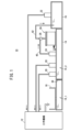
- FIG. 1 is a schematic diagram of a coolant system.
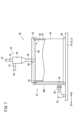
- FIG. 2 is a diagram showing a separation device and a storage device.
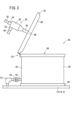
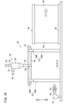
- FIG. 3 shows the separation device and the storage device with the cover open.
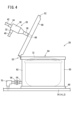
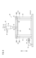
- FIG. 4 is a diagram showing a separation device and a storage device according to the first modified example.
- FIG. 5 is a diagram showing a separation device and a storage device according to the second modification.
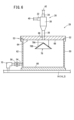
- FIG. 6 is a diagram showing a separation device and a storage device according to the third modification.
- FIG. 7 is a diagram showing a separation device and a storage device according to the fourth modified example.
- FIG. 8 is a diagram showing a separation device according to the fourth modification and a storage device with its cover open.
- FIG. 9 is a diagram showing a separation device and a storage device according to the fifth modified example.
- FIG. 10 is a diagram showing a separation device according to the fifth modification and a storage device with the cover open.
- FIG. 11 is a diagram showing a separation device and a storage device according to the sixth modified example.
- FIG. 1 is a schematic diagram of a coolant system 10.
- the coolant system 10 is a system that separates the machining chips generated by machining of a machine tool 12 from coolant that contains the machining chips, and supplies the coolant from which the machining chips have been separated to the machine tool 12.
- machine tools 12 include cutting machines, lathes, grinding machines, etc.
- Coolant is a liquid. Generally, a water-soluble liquid that is dissolved in water is used as coolant. Coolant is used to improve machining performance when machining is performed by the machine tool 12, to cool machining heat, or to discharge machining chips generated during machining outside the machine.
- the coolant system 10 includes a first liquid tank 14, a second liquid tank 16, a coolant receiving member 18, a first liquid pressure delivery pump 20, a second liquid pressure delivery pump 22, a delivery pump 24, a separation device 26, and a storage device 28.
- the first liquid tank 14 is a tank that stores coolant containing machining debris.
- the first liquid tank 14 is divided into a dirty tank 14_1 and a primary clean tank 14_2 by a porous filter member 30.
- the dirty tank 14_1 and the primary clean tank 14_2 are in communication with each other via the porous filter member 30.
- the porous filter member 30 divides the first liquid tank 14 into the dirty tank 14_1 and the primary clean tank 14_2.
- the porous filter member 30 captures machining debris contained in the coolant stored in the dirty tank 14_1.
- the second liquid tank 16 is a secondary clean tank that stores the coolant from which the machining debris has been separated by the separator 26.
- the coolant stored in the second liquid tank 16 contains almost no machining debris, far less than the machining debris contained in the coolant stored in the primary clean tank 14_2.
- the coolant receiving member 18 is a member for receiving the coolant discharged from the machine tool 12 and sending the coolant to the dirty tank 14_1.
- the coolant discharged from the machine tool 12 contains machining debris.
- the coolant receiving member 18 is installed, for example, on the top plate of the first liquid tank 14.
- the first liquid pressure feed pump 20 is a pump that pressure-feeds the coolant stored in the primary clean tank 14_2 to the machine tool 12.
- the first liquid pressure feed pump 20 is installed, for example, on the top plate of the first liquid tank 14. In FIG. 1, there are two first liquid pressure feed pumps 20, but there may be one, or three or more.
- the coolant pressure-feeded to the machine tool 12 by the first liquid pressure feed pump 20 is supplied to a cleaning nozzle, for example, to discharge machining chips from within the machine tool 12. In this case, the coolant is discharged onto a splash guard or the like of the machine tool 12.
- the second liquid pressure feed pump 22 is a pump that pressure-feeds the coolant stored in the second liquid tank 16 to the machine tool 12.
- the second liquid pressure feed pump 22 is installed, for example, on the top plate of the second liquid tank 16. In FIG. 1, there is one second liquid pressure feed pump 22, but there may be two or more.
- the coolant pressure-feeded to the machine tool 12 by the second liquid pressure feed pump 22 is supplied, for example, to a through hole formed in the spindle of the machine tool 12. In this case, the coolant is discharged from the through hole of a tool attached to the spindle to the machining part of the tool.
- the feed pump 24 is a pump that pressure-feeds the coolant stored in the primary clean tank 14_2 to the separation device 26.
- the feed pump 24 is installed, for example, on the top plate of the first liquid tank 14.
- the first liquid pressure feed pump 20, the second liquid pressure feed pump 22 and the feed pump 24 may be of a positive displacement or non-positive displacement structure.
- FIG. 2 is a diagram showing the separation device 26 and the storage device 28.
- the separation device 26 is a separator that separates the machining debris from the coolant containing the machining debris.
- the separation device 26 may be a cyclone filter.
- the separation device 26 has an input section 32, a clean output section 34, a dirty output section 36, and a main body section 38.
- the input section 32 is provided on the upper side of the main body section 38.
- the input section 32 is connected to the feed pump 24 via the input pipe 40.
- the input section 32 is formed so that the input pipe 40 can be attached and detached.
- the clean output section 34 is provided on the upper part of the main body section 38.
- the clean output section 34 is connected to the second liquid tank 16 via the output pipe 42.
- the clean output section 34 is formed so that the output pipe 42 can be detached.
- the dirty output unit 36 is provided at the bottom of the main body 38.
- the dirty output unit 36 is in communication with the storage container 50 of the storage device 28.
- the dirty output unit 36 is fixed to the storage device 28.
- the main body 38 separates the machining debris from the coolant.
- the separating device 26 is a cyclone filter
- the main body 38 separates the machining debris from the coolant by centrifugal force.
- the coolant flowing in from the input section 32 rotates in the main body 38.
- the machining debris contained in the coolant settles downward while clumping near the outer wall of the cyclone filter due to the centrifugal force caused by the rotation, and flows out from the dirty output section 36 together with some of the coolant.
- the center of the cyclone filter contains almost no machining debris, and clean coolant is discharged from the clean output section 34.
- the storage device 28 is a device that stores the processing waste separated by the separation device 26.
- the storage device 28 includes a storage container 50, a cover 52, a drain section 54, and a valve 56.
- the storage container 50 is a container that stores the machining waste discharged together with the coolant from the dirty output section 36.
- the storage container 50 is placed on a foundation.
- the foundation may be the floor of a room or the ground outdoors.
- the storage container 50 has a bottom wall 60, a side wall 62, and an opening 64.
- the opening 64 is formed at the top opposite the bottom wall 60.
- the storage container 50 may be formed so that the inside of the storage container 50 can be seen from the outside of the storage container 50.
- the entire side wall 62 is formed of transparent resin, glass, etc.
- a window portion may be formed in part of the side wall 62.
- the cover 52 covers the opening 64 of the storage container 50.
- the separation device 26 is connected to the cover 52.
- the cover 52 has a through hole 66.
- the through hole 66 connects the opening 64 of the storage container 50 to the dirty output section 36 of the separation device 26.
- the dirty output section 36 of the separation device 26 is connected to the surface of the cover 52 opposite the opening 64 of the storage container 50. The machining chips that flow out from the dirty output section 36 together with the coolant flow into the storage container 50 via the through hole 66.
- the coolant system 10 may include a support member 53.
- the support member 53 movably supports the cover 52 to open and close the opening 64 of the storage container 50.
- the support member 53 movably connects the cover 52 to the storage container 50.
- An example of the support member 53 is a hinge.
- the support member 53 has a first fixing portion 53A, a second fixing portion 53B, and a shaft 53C.
- the first fixed part 53A is fixed to the cover 52.
- the second fixed part 53B is fixed to the storage container 50.
- the shaft 53C rotatably connects the first fixed part 53A and the second fixed part 53B.
- the shaft 53C is arranged parallel to the base surface on which the storage container 50 is arranged.
- FIG. 3 is a diagram showing the separation device 26 and the storage device 28 with the cover 52 open.
- the cover 52 may have a protrusion 68 protruding from the bottom surface of the cover 52.
- the protrusion 68 limits the level of the liquid, such as coolant, stored in the storage container 50. This makes it possible to prevent the liquid, such as coolant, from leaking from the opening 64 when the cover 52 is opened while the storage container 50 is filled with the liquid, such as coolant.
- the drain section 54 is provided in the storage container 50 so as to be able to communicate with the interior of the storage container 50.
- the drain section 54 discharges liquid such as coolant from the storage container 50.
- the drain section 54 may be a drain pipe connected to the storage container 50.
- an example in which the drain section 54 is a drain pipe is shown in each figure.
- One end of the drain pipe penetrates the lower part of the side wall 62 of the storage container 50 and opens into the interior of the storage container 50.
- the other end of the drain pipe is connected to the first connection part of the joint 70.
- a pipe communicating with the primary clean tank 14_2 is connected to the second connection part of the joint 70.
- the valve 56 opens and closes the drain section 54.
- the valve 56 is closed while the separation device 26 is operating.
- the valve 56 is opened during any open period while the separation device 26 is stopped.
- the open period is a period for cleaning the storage container 50, performing maintenance work, etc.
- the valve 56 may be replaced by a cap or plug that closes the end of the drain portion 54 that communicates with the storage container 50.
- the cap or plug is attached to the end of the drain portion 54 during periods other than the open period.
- the cap or plug is removed from the end of the drain portion 54 during the open period.
- the storage container 50 in which the processing debris is stored is placed on a foundation.
- the capacity for storing processing debris can be increased regardless of the weight of the storage container 50.
- the frequency of cleaning can be reduced.
- the separation device 26 is connected to a cover 52 that covers the opening 64 of the storage container 50. This allows the processing debris stored in the storage container 50 to be removed from the storage container 50 without removing the separation device 26. As a result, cleaning workability can be improved.
- the opening 64 can be opened without separating the cover 52 from the storage container 50.
- the task of placing the separated cover in a stable location is eliminated, reducing the workload.
- a drain section 54 is provided in the storage container 50 so as to be in communication with the inside of the storage container 50.
- the drain section 54 is opened and closed by a valve 56. This makes it possible to prevent machining waste and coolant from leaking out of the storage container 50 while the separation device 26 is in operation. In addition, machining waste and coolant can be discharged from the storage container 50 only during periods when the storage container 50 is being cleaned, maintenance work is being performed, etc.
- (Variation 1) 4 is a diagram showing the separation device 26 and the storage device 28 according to Modification 1.
- the storage device 28 further includes a bag 72.
- Bag 72 is a bag for putting processing waste into. Bag 72 is placed inside storage container 50. Bag 72 is removable from inside storage container 50. Therefore, processing waste can be easily removed from storage container 50 when cleaning, etc., and the inside of storage container 50 can be kept clean.
- the bag 72 may be a mesh bag with holes through which the coolant discharged together with the machining debris can pass.
- the coolant in the storage container 50 can be drained from the drain portion 54 during cleaning, etc., to efficiently collect the machining debris.
- (Variation 2) 5 is a diagram showing the separation device 26 and the storage device 28 according to Modification 2.
- the storage device 28 further includes a porous filter member 76.
- the porous filter member 76 is a member capable of capturing machining debris.
- the porous filter member 76 is disposed inside the storage container 50.
- the porous filter member 76 can be removed from inside the storage container 50. Therefore, by draining the coolant in the storage container 50 from the drain portion 54 during cleaning, machining debris can be efficiently collected.
- the porous filter member 76 may be replaced with a magnet that can attract machining debris. In this case, machining debris can also be efficiently collected by draining the coolant in the storage container 50 from the drain portion 54 during cleaning, etc.
- valve 56 may be open while the separator 26 is in operation, so that the porous filter member 76 captures the processing debris.
- (Variation 3) 6 is a diagram showing the separation device 26 and the storage device 28 according to Modification 3.
- the storage device 28 further includes a guide section 78.
- the guide section 78 is a member that guides the processing waste discharged from the dirty output section 36 of the separation device 26 through the through hole 66 of the cover 52.
- the guide section 78 may be attached to the storage container 50 or to the cover 52.
- the induction portion 78 has a top portion 78A and an outer peripheral portion 78B connected to the top portion 78A.
- the outer peripheral portion 78B extends radially from the top portion 78A toward the periphery of the outer peripheral portion 78B.
- the outer peripheral portion 78B also slopes from the top portion 78A toward the periphery of the outer peripheral portion 78B.
- the induction portion 78 is formed in a cone shape, and the top portion 78A is positioned directly below the through hole 66 of the cover 52.
- the guide section 78 disperses the machining waste discharged from the separation device 26 by using the top section 78A and the outer peripheral section 78B. This makes it possible to prevent the machining waste from being concentrated and accumulated inside the storage container 50. It also makes it possible to reduce the swirling up of the machining waste accumulated inside the storage container 50.
- Fig. 7 is a diagram showing the separation device 26 and the storage device 28 according to Modification 4.
- Fig. 8 is a diagram showing the separation device 26 and the storage device 28 with the cover 52 open according to Modification 4.
- the structure of the support member 53 is different from that of the embodiment.
- the support member 53 has a storage section 80A and a sliding section 80B ( Figure 8).
- the storage section 80A has a hole capable of storing the sliding section 80B.
- the sliding section 80B is attached to the storage section 80A so as to be slidable within the hole of the storage section 80A.
- a first end of the storage section 80A is rotatably connected to the storage container 50.
- a second end of the storage section 80A is formed as an inlet and outlet for the sliding section 80B.
- a first end of the sliding section 80B is connected so as to be slidable within the hole of the storage section 80A.
- a second end of the sliding section 80B is rotatably connected to the cover 52.
- the cover 52 is attached to the storage container 50 so as to be slidable along the opening surface of the opening 64 of the storage container 50. This allows the cover 52 to be opened and closed smoothly even if the weight of the cover 52 is large, compared to the configuration of the support member 53 in the embodiment.
- an inclined portion 82 is formed at the end of the protrusion 68.
- the inclined portion 82 is inclined so that the amount of protrusion from the bottom surface of the cover 52 decreases toward the end. This allows the cover 52 to slide smoothly.
- FIG. 9 is a diagram showing the separation device 26 and the storage device 28 according to Modification 5.
- Fig. 10 is a diagram showing the separation device 26 and the storage device 28 with the cover 52 open according to Modification 5.
- the structure of the support member 53 is different from that of the embodiment.
- the support member 53 has multiple storage sections 90A and multiple slide sections 90B.
- the number of storage sections 90A is the same as the number of slide sections 90B. In this modified example, there are two, but there may be one, or three or more.
- the multiple storage sections 90A have the same configuration.
- the multiple slide sections 90B have the same configuration.
- the storage section 90A has a hole capable of accommodating the sliding section 90B.
- the sliding section 90B is attached to the storage section 90A so as to be slidable within the hole of the storage section 90A.
- a first end of the storage section 90A is connected to the foundation.
- a second end of the storage section 90A is formed as an entrance/exit for the sliding section 90B.
- a first end of the sliding section 90B is connected so as to be slidable within the hole of the storage section 90A.
- a second end of the sliding section 90B is connected to the cover 52.
- the support member 53 extends in the opening direction (upward) D4 away from the opening 64.
- the opening 64 moves away from the cover 52 (see FIG. 10). In this case, the worker can remove the storage container 50 from between the cover 52 and the foundation.
- the cover 52 is attached so as to be movable in a direction perpendicular to the opening surface of the opening 64 of the storage container 50 (open direction D4 or closed direction D3). This allows the cover 52 to be opened without removing the cover 52 from the storage container 50. Also, the storage container 50 can be inserted and removed between the cover 52 and the foundation.
- FIG. 11 is a diagram showing the separation device 26 and the storage device 28 according to the sixth modified example. Note that the drain portion 54 is omitted in Fig. 11. In this modified example, the structure of the support member 53 is different from that of the embodiment.
- the support member 53 has a rotating shaft portion 100.
- the pivot shaft portion 100 supports the cover 52 so that it can pivot relative to the storage container 50.
- the pivot shaft portion 100 is arranged along a direction perpendicular to the base surface on which the storage container 50 is placed.
- the cover 52 is attached to the storage container 50 by the pivot shaft portion 100 so as to be slidable along the opening surface of the opening 64 of the storage container 50. This allows the cover 52 to be opened and closed more smoothly even if the weight of the cover 52 is large, compared to when the cover 52 is opened and closed in a direction perpendicular to the opening surface of the opening 64 of the storage container 50.
- the present disclosure relates to a coolant system (10) that separates machining chips generated by machining of a machine tool (12) from a first liquid that is a liquid containing the machining chips, and supplies a second liquid that is the liquid from which the machining chips have been separated to the machine tool.
- the coolant system of the present disclosure includes a separation device (26) that separates the machining chips contained in the first liquid pumped up from a first liquid tank (14) that stores the first liquid from the first liquid, and a storage device (28) that stores the machining chips separated by the separation device.
- the storage device includes a storage container (50) that is placed on a foundation and stores the machining chips, and a cover (52) to which the separation device is connected and that covers an opening (64) of the storage container.
- a support member (53) may be provided for movably supporting the cover with respect to the storage container and opening and closing the opening. This can reduce the load required to move the cover.
- the cover may be rotatably attached to the storage container. This allows the opening to be opened and closed without removing the cover from the storage container. As a result, the operation of removing the cover is eliminated, and the workload can be reduced.
- the cover may be attached to the storage container so as to be slidable along the opening surface of the opening. This allows the opening to be opened and closed without removing the cover from the storage container. As a result, the work of removing the cover is eliminated, and the workload can be reduced. In addition, compared to a case where the cover and the storage container are connected via a hinge or the like, the cover can be opened and closed smoothly even if the cover is heavy.
- the cover may be attached so as to be movable in a direction perpendicular to the opening surface of the opening. This allows the opening to be opened and closed without removing the cover from the storage container. As a result, the work of removing the cover is eliminated, and the workload can be reduced. In addition, the storage container can be inserted and removed between the cover and the foundation.
- the cover may have a protrusion (68) protruding from a bottom surface of the cover, and the protrusion may face an upper portion of an inner circumferential surface of the side wall (62) of the storage container when the opening is closed. This makes it possible to prevent the liquid such as coolant from leaking from the opening when the cover is opened with the storage container filled with the liquid such as coolant.
- the coolant system according to any one of Supplementary Note 1 to Supplementary Note 6 may include a drain portion (54) provided in the storage container so as to be capable of communicating with the inside of the storage container, and a valve (56) capable of opening and closing the drain portion. This makes it possible to prevent the machining waste and coolant from flowing out of the storage container during operation of the separation device. In addition, the machining waste and coolant can be discharged from the storage container only during periods such as cleaning and maintenance work of the storage container.
- the coolant system according to any one of Supplementary Note 1 to Supplementary Note 7 may include a bag (72) that is disposed inside the storage container and is removable from the inside of the storage container, for storing the processing waste. This makes it possible to easily remove the processing waste from the storage container, and also makes it possible to keep the inside of the storage container clean.
- the coolant system according to any one of Supplementary Note 1 to Supplementary Note 8 may further include a porous filter member (76) that is disposed inside the storage container so as to be removable from the inside of the storage container and captures the machining debris. This allows the machining debris to be efficiently collected by draining the liquid in the storage container from the drain portion during cleaning or the like.
- the storage container may be formed so that the inside of the storage container can be visually confirmed from the outside of the storage container. This makes it possible to check the storage state of the storage container without opening a cover.
- the coolant system according to any one of Supplementary Note 1 to Supplementary Note 10 may further include a second liquid pressure-feed pump (22) that pressure-feeds the second liquid from a second liquid tank (16) in which the second liquid supplied from the separating device is stored to the machine tool. This makes it possible to appropriately supply the second liquid to the machine tool.
- a second liquid pressure-feed pump (22) that pressure-feeds the second liquid from a second liquid tank (16) in which the second liquid supplied from the separating device is stored to the machine tool. This makes it possible to appropriately supply the second liquid to the machine tool.
Landscapes
- Engineering & Computer Science (AREA)
- Mechanical Engineering (AREA)
- Auxiliary Devices For Machine Tools (AREA)
Abstract
Description
図4は、変形例1による分離装置26および貯留装置28を示す図である。本変形例では、貯留装置28は、袋72をさらに備える。
図5は、変形例2による分離装置26および貯留装置28を示す図である。本変形例では、貯留装置28は、多孔性フィルタ部材76をさらに備える。
図6は、変形例3による分離装置26および貯留装置28を示す図である。本変形例では、貯留装置28は、誘導部78をさらに備える。
図7は、変形例4による分離装置26および貯留装置28を示す図である。図8は、変形例4による分離装置26およびカバー52が開いた貯留装置28を示す図である。本変形例では、支持部材53の構造が実施形態と異なる。
図9は、変形例5による分離装置26および貯留装置28を示す図である。図10は、変形例5による分離装置26およびカバー52が開いた貯留装置28を示す図である。本変形例では、支持部材53の構造が実施形態と異なる。
図11は、変形例6による分離装置26および貯留装置28を示す図である。なお、図11では、ドレン部54は省略されている。本変形例では、支持部材53の構造が実施形態と異なる。支持部材53は、旋回軸部100を有する。
本開示は、工作機械(12)の加工により生じた加工屑を含む液体である第1液から前記加工屑を分離し、前記加工屑が分離された前記液体である第2液を前記工作機械に供給するクーラントシステム(10)である。本開示のクーラントシステムは、前記第1液を貯留する第1液槽(14)から汲み上げられた前記第1液に含まれる前記加工屑を前記第1液から分離する分離装置(26)と、前記分離装置によって分離された前記加工屑を貯留する貯留装置(28)と、を備える。前記貯留装置は、基礎上に配置され、前記加工屑が貯留される貯留容器(50)と、前記分離装置が接続され、前記貯留容器の開口部(64)を覆うカバー(52)と、を備える。
付記1に記載のクーラントシステムであって、前記貯留容器に対して前記カバーを移動可能に支持して、前記開口部を開閉する支持部材(53)を備えてもよい。これにより、カバーを移動する負荷を軽減することができる。
付記1または2に記載のクーラントシステムであって、前記カバーは、回転可能に前記貯留容器に取り付けられてもよい。これにより、貯留容器からカバーを外すことなく開口部を開閉することができる。その結果、カバーを外す作業がなくなり、作業負荷を軽減することができる。
付記1または2に記載のクーラントシステムであって、前記カバーは、前記開口部の開口面に沿ってスライド可能に前記貯留容器に取り付けられてもよい。これにより、貯留容器からカバーを外すことなく開口部を開閉することができる。その結果、カバーを外す作業がなくなり、作業負荷を軽減することができる。また、カバーと貯留容器とが蝶番等を介して連結される場合に比べて、カバーの重量が大きくても、カバーの開閉を滑らかにすることができる。
付記1に記載のクーラントシステムであって、前記カバーは、前記開口部の開口面に直交する方向に移動可能に取り付けられてもよい。これにより、貯留容器からカバーを外すことなく開口部を開閉することができる。その結果、カバーを外す作業がなくなり、作業負荷を軽減することができる。また、カバーと基礎との間から貯留容器の出し入れが可能となる。
付記1~付記5のいずれかに記載のクーラントシステムであって、前記カバーは、前記カバーの底面から突出する凸部(68)を有し、前記凸部は、前記開口部が閉じられている状態において前記貯留容器の側壁(62)における内周面の上部に向いていてもよい。これにより、貯留容器内がクーラント等の液体で満たされた状態でカバーを開けた際、クーラント等の液体が開口部から漏れることを防止することができる。
付記1~付記6のいずれかに記載のクーラントシステムは、前記貯留容器の内部と連通可能に前記貯留容器に設けられるドレン部(54)と、前記ドレン部を開閉可能なバルブ(56)とを備えてもよい。これにより、分離装置の作動中に貯留容器から加工屑およびクーラントが流出することを回避することができる。また、貯留容器の洗浄、メンテナンス作業等の期間に限って貯留容器から加工屑およびクーラント等を排出することができる。
付記1~付記7のいずれかに記載のクーラントシステムは、前記貯留容器の内部から取り出し可能に前記貯留容器の内部に配置され、前記加工屑を入れる袋(72)を備えてもよい。これにより、貯留容器から加工屑を容易に取り出すことができ、また、貯留容器の内部を清潔に保つことができる。
付記1~付記8のいずれかに記載のクーラントシステムは、前記貯留容器の内部から取り出し可能に前記貯留容器の内部に配置され、前記加工屑を捕捉する多孔性フィルタ部材(76)を備えてもよい。これにより、清掃時等にドレン部から貯留容器内の液体を抜くことで、加工屑を効率よく収集することができる。
付記1~付記9のいずれかに記載のクーラントシステムであって、前記貯留容器は、前記貯留容器の内部を前記貯留容器の外部から視認可能に形成されてもよい。これにより、カバーを開けなくても貯留容器の貯留状態を確認することができる。
付記1~付記10のいずれかに記載のクーラントシステムであって、前記分離装置から供給される前記第2液が貯留される第2液槽(16)から前記工作機械に前記第2液を圧送する第2液圧送ポンプ(22)を備えてもよい。これにより、第2液を工作機械に適切に供給することができる。
14…第1液槽 16…第2液槽
18…クーラント受け部材 20…第1液圧送ポンプ
22…第2液圧送ポンプ 24…送りポンプ
26…分離装置 28…貯留装置
30…多孔性フィルタ部材 50…貯留容器
52…カバー 53…支持部材
54…ドレン部 56…バルブ
62…側壁 64…開口部
72…袋 78…誘導部
Claims (11)
- 工作機械の加工により生じた加工屑を含む液体である第1液から前記加工屑を分離し、前記加工屑が分離された前記液体である第2液を前記工作機械に供給するクーラントシステムであって、
前記第1液を貯留する第1液槽から汲み上げられた前記第1液に含まれる前記加工屑を前記第1液から分離する分離装置と、
前記分離装置によって分離された前記加工屑を貯留する貯留装置と、
を備え、
前記貯留装置は、
基礎上に配置され、前記加工屑が貯留される貯留容器と、
前記分離装置が接続され、前記貯留容器の開口部を覆うカバーと、
を備える、クーラントシステム。 - 請求項1に記載のクーラントシステムであって、
前記貯留容器に対して前記カバーを移動可能に支持して、前記開口部を開閉する支持部材を備える、クーラントシステム。 - 請求項1または2に記載のクーラントシステムであって、
前記カバーは、回転可能に貯留容器に取り付けられる、クーラントシステム。 - 請求項1または2に記載のクーラントシステムであって、
前記カバーは、前記開口部の開口面に沿ってスライド可能に前記貯留容器に取り付けられる、クーラントシステム。 - 請求項1に記載のクーラントシステムであって、
前記カバーは、前記開口部の開口面に直交する方向に移動可能に取り付けられる、クーラントシステム。 - 請求項1~5のいずれか1項に記載のクーラントシステムであって、
前記カバーは、前記カバーの底面から突出する凸部を有し、前記凸部は、前記開口部が閉じられている状態において前記貯留容器の側壁における内周面の上部に向く、クーラントシステム。 - 請求項1~6のいずれか1項に記載のクーラントシステムであって、
前記貯留容器の内部と連通可能に前記貯留容器に設けられるドレン部と、
前記ドレン部を開閉可能なバルブと、
を備える、クーラントシステム。 - 請求項1~7のいずれか1項に記載のクーラントシステムであって、
前記貯留容器の内部から取り出し可能に前記貯留容器の内部に配置され、前記加工屑を入れる袋を備える、クーラントシステム。 - 請求項1~8のいずれか1項に記載のクーラントシステムであって、
前記貯留容器の内部から取り出し可能に前記貯留容器の内部に配置され、前記加工屑を捕捉する多孔性フィルタ部材を備える、クーラントシステム。 - 請求項1~9のいずれか1項に記載のクーラントシステムであって、
前記貯留容器は、前記貯留容器の内部を前記貯留容器の外部から視認可能に形成される、クーラントシステム。 - 請求項1~10のいずれか1項に記載のクーラントシステムであって、
前記分離装置から供給される前記第2液が貯留される第2液槽から前記工作機械に前記第2液を圧送する第2液圧送ポンプを備える、クーラントシステム。
Priority Applications (4)
| Application Number | Priority Date | Filing Date | Title |
|---|---|---|---|
| CN202380093119.5A CN120641242A (zh) | 2023-02-09 | 2023-02-09 | 冷却液系统 |
| JP2024575997A JPWO2024166303A1 (ja) | 2023-02-09 | 2023-02-09 | |
| DE112023005060.0T DE112023005060T5 (de) | 2023-02-09 | 2023-02-09 | Kühlmittelsystem |
| PCT/JP2023/004395 WO2024166303A1 (ja) | 2023-02-09 | 2023-02-09 | クーラントシステム |
Applications Claiming Priority (1)
| Application Number | Priority Date | Filing Date | Title |
|---|---|---|---|
| PCT/JP2023/004395 WO2024166303A1 (ja) | 2023-02-09 | 2023-02-09 | クーラントシステム |
Publications (1)
| Publication Number | Publication Date |
|---|---|
| WO2024166303A1 true WO2024166303A1 (ja) | 2024-08-15 |
Family
ID=92262175
Family Applications (1)
| Application Number | Title | Priority Date | Filing Date |
|---|---|---|---|
| PCT/JP2023/004395 Ceased WO2024166303A1 (ja) | 2023-02-09 | 2023-02-09 | クーラントシステム |
Country Status (4)
| Country | Link |
|---|---|
| JP (1) | JPWO2024166303A1 (ja) |
| CN (1) | CN120641242A (ja) |
| DE (1) | DE112023005060T5 (ja) |
| WO (1) | WO2024166303A1 (ja) |
Citations (8)
| Publication number | Priority date | Publication date | Assignee | Title |
|---|---|---|---|---|
| JP2003225515A (ja) * | 2001-11-27 | 2003-08-12 | Takahashi:Kk | フィルタ装置 |
| WO2008035551A1 (en) * | 2006-09-21 | 2008-03-27 | Sumitomo Heavy Industries Finetech, Ltd. | Coolant cleaning device for machine tool |
| JP2013107164A (ja) * | 2011-11-21 | 2013-06-06 | Industria:Kk | 微細物除去装置及び微細物除去システム |
| JP2013154432A (ja) * | 2012-01-30 | 2013-08-15 | Kazuo Mitsui | クーラントタンク掃除機 |
| JP2014087744A (ja) * | 2012-10-30 | 2014-05-15 | Nikuni Corp | 濾過装置 |
| CN205085732U (zh) * | 2015-11-02 | 2016-03-16 | 吴善方 | 自动过滤回收烘干的环保机床 |
| JP2016165775A (ja) * | 2015-03-10 | 2016-09-15 | 株式会社日進製作所 | 液体浄化システム |
| JP2021146418A (ja) * | 2020-03-17 | 2021-09-27 | 株式会社ディスコ | 廃液処理装置、及び加工粉回収装置 |
-
2023
- 2023-02-09 DE DE112023005060.0T patent/DE112023005060T5/de active Pending
- 2023-02-09 CN CN202380093119.5A patent/CN120641242A/zh active Pending
- 2023-02-09 WO PCT/JP2023/004395 patent/WO2024166303A1/ja not_active Ceased
- 2023-02-09 JP JP2024575997A patent/JPWO2024166303A1/ja active Pending
Patent Citations (8)
| Publication number | Priority date | Publication date | Assignee | Title |
|---|---|---|---|---|
| JP2003225515A (ja) * | 2001-11-27 | 2003-08-12 | Takahashi:Kk | フィルタ装置 |
| WO2008035551A1 (en) * | 2006-09-21 | 2008-03-27 | Sumitomo Heavy Industries Finetech, Ltd. | Coolant cleaning device for machine tool |
| JP2013107164A (ja) * | 2011-11-21 | 2013-06-06 | Industria:Kk | 微細物除去装置及び微細物除去システム |
| JP2013154432A (ja) * | 2012-01-30 | 2013-08-15 | Kazuo Mitsui | クーラントタンク掃除機 |
| JP2014087744A (ja) * | 2012-10-30 | 2014-05-15 | Nikuni Corp | 濾過装置 |
| JP2016165775A (ja) * | 2015-03-10 | 2016-09-15 | 株式会社日進製作所 | 液体浄化システム |
| CN205085732U (zh) * | 2015-11-02 | 2016-03-16 | 吴善方 | 自动过滤回收烘干的环保机床 |
| JP2021146418A (ja) * | 2020-03-17 | 2021-09-27 | 株式会社ディスコ | 廃液処理装置、及び加工粉回収装置 |
Also Published As
| Publication number | Publication date |
|---|---|
| JPWO2024166303A1 (ja) | 2024-08-15 |
| CN120641242A (zh) | 2025-09-12 |
| DE112023005060T5 (de) | 2025-09-25 |
Similar Documents
| Publication | Publication Date | Title |
|---|---|---|
| US6571959B1 (en) | Coolant fluid cleaning method and apparatus | |
| EP2065127A1 (en) | Coolant cleaning device for machine tool | |
| JP5264001B1 (ja) | 浮上油分離回収装置 | |
| US9422926B2 (en) | Pump device | |
| JP7133736B1 (ja) | クーラント供給装置 | |
| JP7235664B2 (ja) | クーラント液処理システム及びフロート式逆止弁 | |
| JP2016182592A (ja) | オイルミスト集塵機 | |
| WO2024166303A1 (ja) | クーラントシステム | |
| CN109847954A (zh) | 便于维护的全自动喷洒式离心分离设备 | |
| KR101531858B1 (ko) | 공작기계용 고압 절삭유 공급 장치 | |
| KR20220114245A (ko) | 진공을 이용한 절삭 슬러지 여과 장치 | |
| KR200149338Y1 (ko) | 절삭유 탱크의 유수분리장치 | |
| WO2024224622A1 (ja) | 貯留装置およびクーラントシステム | |
| KR101760901B1 (ko) | 드레인 필터가 마련된 오일 미스트 집진기 | |
| JP7594666B2 (ja) | 工作機械 | |
| KR101539424B1 (ko) | 절삭유 여과장치 | |
| KR200404946Y1 (ko) | 공작기계용 절삭유 세정장치 | |
| CN109224581A (zh) | 刮刀式过滤器 | |
| KR200143025Y1 (ko) | 공작기계의 칩 팬 분리형 절삭유 탱크 | |
| JPS6310833Y2 (ja) | ||
| KR102939711B1 (ko) | 쿨런트 공급장치 | |
| JP7711156B2 (ja) | クーラントタンク、及び、工作機械 | |
| JP3547294B2 (ja) | 油圧装置 | |
| JP4079029B2 (ja) | 加工機におけるミスト回収機構 | |
| KR20210083562A (ko) | 3상 원심분리기 |
Legal Events
| Date | Code | Title | Description |
|---|---|---|---|
| 121 | Ep: the epo has been informed by wipo that ep was designated in this application |
Ref document number: 23921134 Country of ref document: EP Kind code of ref document: A1 |
|
| WWE | Wipo information: entry into national phase |
Ref document number: 2024575997 Country of ref document: JP |
|
| WWE | Wipo information: entry into national phase |
Ref document number: 112023005060 Country of ref document: DE Ref document number: 202380093119.5 Country of ref document: CN |
|
| WWP | Wipo information: published in national office |
Ref document number: 202380093119.5 Country of ref document: CN |
|
| WWP | Wipo information: published in national office |
Ref document number: 112023005060 Country of ref document: DE |
|
| 122 | Ep: pct application non-entry in european phase |
Ref document number: 23921134 Country of ref document: EP Kind code of ref document: A1 |