WO2024166301A1 - Measurement device, power storage system and measurement method - Google Patents
Measurement device, power storage system and measurement method Download PDFInfo
- Publication number
- WO2024166301A1 WO2024166301A1 PCT/JP2023/004389 JP2023004389W WO2024166301A1 WO 2024166301 A1 WO2024166301 A1 WO 2024166301A1 JP 2023004389 W JP2023004389 W JP 2023004389W WO 2024166301 A1 WO2024166301 A1 WO 2024166301A1
- Authority
- WO
- WIPO (PCT)
- Prior art keywords
- storage battery
- current
- impedance
- voltage
- pulse signal
- Prior art date
- Legal status (The legal status is an assumption and is not a legal conclusion. Google has not performed a legal analysis and makes no representation as to the accuracy of the status listed.)
- Ceased
Links
Images


Classifications
-
- G—PHYSICS
- G01—MEASURING; TESTING
- G01R—MEASURING ELECTRIC VARIABLES; MEASURING MAGNETIC VARIABLES
- G01R31/00—Arrangements for testing electric properties; Arrangements for locating electric faults; Arrangements for electrical testing characterised by what is being tested not provided for elsewhere
- G01R31/36—Arrangements for testing, measuring or monitoring the electrical condition of accumulators or electric batteries, e.g. capacity or state of charge [SoC]
- G01R31/389—Measuring internal impedance, internal conductance or related variables
-
- G—PHYSICS
- G01—MEASURING; TESTING
- G01R—MEASURING ELECTRIC VARIABLES; MEASURING MAGNETIC VARIABLES
- G01R23/00—Arrangements for measuring frequencies; Arrangements for analysing frequency spectra
- G01R23/16—Spectrum analysis; Fourier analysis
-
- G—PHYSICS
- G01—MEASURING; TESTING
- G01R—MEASURING ELECTRIC VARIABLES; MEASURING MAGNETIC VARIABLES
- G01R27/00—Arrangements for measuring resistance, reactance, impedance, or electric characteristics derived therefrom
- G01R27/02—Measuring real or complex resistance, reactance, impedance, or other two-pole characteristics derived therefrom, e.g. time constant
- G01R27/08—Measuring resistance by measuring both voltage and current
-
- G—PHYSICS
- G01—MEASURING; TESTING
- G01R—MEASURING ELECTRIC VARIABLES; MEASURING MAGNETIC VARIABLES
- G01R31/00—Arrangements for testing electric properties; Arrangements for locating electric faults; Arrangements for electrical testing characterised by what is being tested not provided for elsewhere
- G01R31/36—Arrangements for testing, measuring or monitoring the electrical condition of accumulators or electric batteries, e.g. capacity or state of charge [SoC]
- G01R31/367—Software therefor, e.g. for battery testing using modelling or look-up tables
-
- G—PHYSICS
- G01—MEASURING; TESTING
- G01R—MEASURING ELECTRIC VARIABLES; MEASURING MAGNETIC VARIABLES
- G01R31/00—Arrangements for testing electric properties; Arrangements for locating electric faults; Arrangements for electrical testing characterised by what is being tested not provided for elsewhere
- G01R31/36—Arrangements for testing, measuring or monitoring the electrical condition of accumulators or electric batteries, e.g. capacity or state of charge [SoC]
- G01R31/382—Arrangements for monitoring battery or accumulator variables, e.g. SoC
- G01R31/3842—Arrangements for monitoring battery or accumulator variables, e.g. SoC combining voltage and current measurements
-
- G—PHYSICS
- G01—MEASURING; TESTING
- G01R—MEASURING ELECTRIC VARIABLES; MEASURING MAGNETIC VARIABLES
- G01R31/00—Arrangements for testing electric properties; Arrangements for locating electric faults; Arrangements for electrical testing characterised by what is being tested not provided for elsewhere
- G01R31/36—Arrangements for testing, measuring or monitoring the electrical condition of accumulators or electric batteries, e.g. capacity or state of charge [SoC]
- G01R31/392—Determining battery ageing or deterioration, e.g. state of health
Definitions
- Embodiments of the present invention relate to a measuring device, a power storage system, and a measuring method.
- the frequency characteristics of the impedance of the battery are measured.
- a current waveform whose current value changes periodically is input to the battery at each of multiple frequencies, and the time change in the voltage of the battery is measured while the current waveform is input to the battery.
- the impedance of the battery at each of multiple frequencies is measured, and the frequency characteristics of the impedance of the battery are measured.
- the problem that the present invention aims to solve is to provide a measurement device, a power storage system, and a measurement method that enable the impedance of a storage battery to be measured with a simple configuration and improves the convenience of charging the storage battery and measuring its impedance.
- the measurement device includes a processing circuit that inputs a pseudo-random pulse signal of current, which changes between a first current value greater than zero and a second current value greater than the first current value, to the storage battery.
- the processing circuit measures the impedance of the storage battery based on the pseudo-random pulse signal of current input to the storage battery and the change over time in the voltage of the storage battery while the pseudo-random pulse signal of current is input to the storage battery.
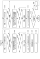
- FIG. 1 is a schematic diagram illustrating an example of a power storage system according to a first embodiment.
- FIG. 2 is a schematic diagram showing an example of the change over time of the charging current output from the power supply circuit, the pseudo-random pulse signal of the current input to the storage battery, and the bypass current diverted from the charging current in the first embodiment.
- FIG. 3 is a schematic diagram showing an example of an analog signal indicating the time change in the voltage (terminal voltage) of a storage battery when a pseudo-random pulse signal of current is input to the storage battery in the first embodiment, and an example of an analog signal for the voltage after the analog signal indicating the time change in the voltage is processed by a band-pass filter.
- FIG. 4 is a schematic diagram showing an example of a process for measuring frequency characteristics of impedance of a storage battery, which is performed by the data processing unit of the process execution unit in the first embodiment.
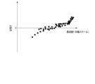
- FIG. 5 is a schematic diagram showing an example of impedance spectrum data regarding the frequency characteristics of the impedance of the storage battery measured in the first embodiment, in the form of a complex impedance plot.
- FIG. 6 is a schematic diagram showing an example of a relationship between frequency and the absolute value of the impedance of the storage battery, which is indicated by impedance spectrum data regarding the frequency characteristics of the impedance of the storage battery measured in the first embodiment.
- FIG. 5 is a schematic diagram showing an example of impedance spectrum data regarding the frequency characteristics of the impedance of the storage battery measured in the first embodiment, in the form of a complex impedance plot.
- FIG. 6 is a schematic diagram showing an example of a relationship between frequency and the absolute value of the impedance of the storage battery, which is indicated by impedance spectrum data regarding the frequency characteristics
- FIG. 7 is a schematic diagram showing an example of the relationship of the phase of the impedance of the storage battery with respect to the frequency, which is indicated by impedance spectrum data regarding the frequency characteristics of the impedance of the storage battery measured in the first embodiment.
- FIG. 8 is a schematic diagram illustrating an example of averaging processing performed by the data processing unit 26 on impedance spectrum data, which is measurement data of the frequency characteristics of the impedance of the storage battery, in the first embodiment.
- FIG. 9 is a schematic diagram showing another example of the process of measuring the frequency characteristic of the impedance of the storage battery, which is performed by the data processing unit of the process execution unit in the first embodiment, different from that shown in FIG. FIG.
- FIG. 10 is a schematic diagram illustrating an example of resampling of voltage time-series data (first voltage time-series data) performed by the data processing unit in the first embodiment.
- FIG. 11 is a schematic diagram illustrating an example of a data selection process performed on two pieces of averaged data by the data processing unit in the first embodiment.
- FIG. 12 is a flowchart illustrating an example of a process performed by the process execution unit in determining the state of the storage battery in the first embodiment.
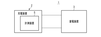
- FIG. 13 is a schematic diagram illustrating an example of a power storage system according to a first modified example.
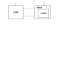
- FIG. 14 is a schematic diagram illustrating an example of a power storage system according to a second modified example.
- FIG. 1 shows an example of a power storage system 1 according to the first embodiment.
- the power storage system 1 includes a charging device 2 such as a charger, a power storage device 3, and a measuring device 5, and the power storage device 3 includes a storage battery 6.
- the charging device 2, the power storage device 3, and the measuring device 5 are provided separately from each other.
- the power storage device 3 is mounted on, for example, a battery-mounted device (not shown). Examples of battery-mounted devices on which the power storage device 3 is mounted include factory transport vehicles such as AGVs (Automatic Guided Vehicles), stationary power supply devices, smartphones, vehicles such as electric cars, robots, drones, and the like.
- AGVs Automatic Guided Vehicles
- the storage battery 6 mounted on the power storage device 3 is, for example, a secondary battery such as a lithium-ion secondary battery.
- the storage battery 6 may be formed from a single cell (single battery), or may be a battery module or cell block formed by electrically connecting a plurality of single cells.
- the plurality of single cells may be electrically connected in series in the storage battery 6, or may be electrically connected in parallel in the storage battery 6.
- the storage battery 6 may be formed in both a series connection structure in which a plurality of single cells are connected in series, and a parallel connection structure in which a plurality of single cells are connected in parallel.
- the storage battery 6 may be either a battery string or a battery array in which a plurality of battery modules are electrically connected.
- the charging device 2 supplies power to the storage battery 6 when charging the storage battery 6.
- the charging device 2 includes a power supply circuit 11, a control unit 12 such as a control circuit, and a memory unit 13.
- a charging current Ic is output from the power supply circuit 11 to the storage battery 6.
- the supply path of the charging current Ic from the power supply circuit 11 to the storage battery 6 is formed through the measuring device 5.
- the charging device 2 includes a processor or integrated circuit, etc., and a storage medium such as a memory.
- the processor or integrated circuit, etc. includes any of a CPU (Central Processing Unit), an ASIC (Application Specific Integrated Circuit), a microcomputer, an FPGA (Field Programmable Gate Array), and a DSP (Digital Signal Processor).
- the charging device 2 may be provided with only one processor, etc., or may be provided with multiple processors. Also, the charging device 2 may be provided with only one storage medium, or may be provided with multiple storage mediums.
- the processor or integrated circuit, etc. performs processing by, for example, executing a program stored in the storage medium. Also, in the charging device 2, the processing of the control unit 12 is performed by the processor, etc., and the storage medium functions as the storage unit 13.
- control unit 12 controls the operation of the power supply circuit 11 to control the supply of power to the storage battery 6.
- the control unit 12 also controls the operation of the power supply circuit 11 to adjust the charging rate of the charging current Ic output from the power supply circuit 11 to the storage battery 6, etc.
- the measuring device 5 includes a current detection circuit 15 and a voltage detection circuit 16.
- the current detection circuit 15 detects an input current Ii to the storage battery 6, which is a current flowing through the storage battery 6, and the voltage detection circuit 16 detects a voltage Vd applied to the storage battery 6.
- the current detection circuit 15 includes, for example, a shunt resistor, and detects the current (input current Ii) of the storage battery 6 based on the voltage applied to the shunt resistor.
- the voltage detection circuit 16 detects, for example, the voltage between the terminals of the storage battery 6 as the voltage Vd of the storage battery 6.
- the current detection circuit 15 and the voltage detection circuit 16 may be provided in the power storage device 3.
- the measuring device 5 measures the impedance Z of the storage battery 6.
- the measuring device 5 measures the impedance Z of the storage battery 6 when the storage battery 6 is being charged by the charging current Ic output from the power supply circuit 11 to the storage battery 6.
- the measuring device 5 includes a processing execution unit 21 such as a processing circuit, and a memory unit 22, and the processing execution unit 21 includes an input current adjustment unit 25 and a data processing unit 26.
- the input current adjustment unit 25 and the data processing unit 26 each execute a part of the processing performed by the processing execution unit 21.
- the measurement device 5 includes a processor or integrated circuit, etc., and a storage medium such as a memory.
- the processor or integrated circuit, etc. includes any of a CPU, ASIC, microcomputer, FPGA, and DSP.
- the measurement device 5 may be provided with only one processor, etc., or may be provided with multiple processors. Also, the measurement device 5 may be provided with only one storage medium, or may be provided with multiple storage media.
- the processor or integrated circuit, etc. performs processing by, for example, executing a program stored in the storage medium.
- the processing of the processing execution unit 21 is performed by the processor, etc., and the storage medium functions as the storage unit 22.
- the measuring device 5 also includes a drive circuit 31, and in the example shown in FIG. 1, the drive circuit 31 includes a switch 32 and a resistor 34.
- the drive circuit 31 is formed in a supply path of the charging current Ic from the power supply circuit 11 of the charging device 2 to the storage battery 6 of the power storage device 3.
- the input current adjustment unit 25 of the processing execution unit 21 controls the drive of the drive circuit 31 when the charging current Ic is being output from the power supply circuit 11 to the storage battery 6, and controls, for example, the on/off of the switch 32. This adjusts and controls the input current Ii input to the storage battery 6.
- the input current adjustment unit 25 controls the shunting of the charging current Ic in the drive circuit 31 by controlling the switching operation of the switch 32, i.e., by controlling the on/off of the switch 32.
- the input current adjustment unit 25 controls the shunting of the charging current Ic in the drive circuit 31 to generate a pseudo-random pulse signal of current, and inputs the generated pseudo-random pulse signal of current to the storage battery 6 as the input current Ii to the storage battery 6. Therefore, in this embodiment, the processing execution unit 21 such as a processing circuit shunts the charging current Ic output from the power supply circuit 11 to the storage battery 6 in measuring the impedance Z of the storage battery 6, thereby generating a pseudo-random pulse signal of current as the input current Ii to the storage battery 6.
- the pseudo-random pulse signal uses, for example, an M-series signal.
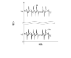
- FIG. 2 shows an example of the change over time of the charging current Ic output from the power supply circuit 11, the pseudo-random pulse signal of the current which is the input current Ii input to the storage battery 6, and the bypass current Ib diverted from the charging current Ic.
- the horizontal axis shows time t
- the vertical axis shows the current I.
- the charging current Ic is kept constant or approximately constant over time at a current value I ⁇ . Then, when the switch 32 of the drive circuit 31 is in the off state, the charging current Ic is not diverted, the pseudo-random pulse signal (input current Ii) has a current value I ⁇ , and the bypass current Ib has a current value of 0.
- the switch 32 of the drive circuit 31 when the switch 32 of the drive circuit 31 is in the on state, a current equivalent to the current value I ⁇ is diverted from the charging current Ic as the bypass current Ib, and the pseudo-random pulse signal (input current Ii) has a current value I ⁇ -I ⁇ .
- the current value I ⁇ is less than half the current value I ⁇ , for example, about 10% of the current value I ⁇ .
- the charging current Ic, the pseudo-random pulse signal (input current Ii), and the bypass current Ib each change over time, so in the example of FIG. 2, the bypass current Ib changes over time between zero and a current value I ⁇ .
- the pseudo-random pulse signal changes over time between a current value (first current value) I ⁇ -I ⁇ that is greater than zero and a current value (second current value) I ⁇ that is greater than the current value I ⁇ -I ⁇ .
- the pseudorandom pulse signal includes a plurality of pulses p, and the current value of each of the plurality of pulses p is lower than the current value I ⁇ .
- a pulse width w is specified for each of the plurality of pulses p, and at least one of the plurality of pulses p has a pulse width w different from the other pulses p.
- a pulse pmin having the smallest pulse width w among the pulses p of the pseudorandom pulse signal is specified, and a pulse width wmin of the pulse pmin is specified.
- the pulse width w of each of the plurality of pulses p is an integer multiple of the pulse width wmin of the pulse pmin.
- a signal length Y is specified for the pseudorandom pulse signal.
- the signal length Y of the pseudorandom pulse signal corresponds to the time from the start to the end of the switching operation of the switch 32.
- the measurement device 5 also includes an A/D converter 33 and a band pass filter (BPF) 35.
- the A/D converter 33 receives analog signals indicating the detection results of the current detection circuit 15 and the voltage detection circuit 16.
- the A/D converter 33 converts the analog signal indicating the detection result in the current detection circuit 15, i.e., the analog signal indicating the detection result of the input current Ii input to the storage battery 6, into a digital signal.
- the A/D converter 33 also converts the analog signal indicating the detection result in the voltage detection circuit 16, i.e., the analog signal indicating the change over time in the voltage (terminal voltage) Vd of the storage battery 6, into a digital signal.
- the A/D converter 33 performs sampling at a predetermined sampling period and converts the analog signal into a digital signal.
- the analog signal indicating the detection result of the voltage detection circuit 16 is directly input to the A/D converter 33 as described above, and the analog signal indicating the detection result of the voltage detection circuit 16 is also input through the bandpass filter 35.
- the bandpass filter 35 extracts only voltage components in a specific frequency range from the analog signal indicating the time change of the voltage (terminal voltage) Vd of the storage battery 6, and removes voltage components outside the specific frequency range.
- the specific frequency range does not include 0 Hz, and in one example, the specific frequency range is a frequency range of 0.1 Hz or more and 5000 Hz or less. Therefore, the bandpass filter 35 removes the voltage component of 0 Hz, that is, the voltage component caused by direct current, from the analog signal indicating the detection result of the voltage detection circuit 16.
- Figure 3 shows an example of an analog signal indicating the time change in voltage (terminal voltage) Vd of the storage battery 6 when a pseudo-random pulse signal of current is input to the storage battery 6 as the input current Ii, and an analog signal for voltage Vm after the analog signal indicating the time change in voltage Vd is processed by band-pass filter 35.
- the horizontal axis indicates time t
- the vertical axis indicates voltage V.
- the voltage Vd fluctuates around a voltage value V ⁇ and has a voltage offset corresponding to the voltage value V ⁇ with respect to 0V.
- the voltage Vm fluctuates around a voltage value V ⁇ that is closer to 0V than the voltage value V ⁇ and has a voltage offset corresponding to the voltage value V ⁇ with respect to 0V. Therefore, in the analog signal showing the time change of the voltage Vm, the center of the fluctuation is closer to 0V and the voltage offset with respect to 0V is reduced compared to the analog signal showing the time change of the voltage Vd.
- the voltage offset with respect to 0V is reduced by an amount equivalent to the open circuit voltage of the storage battery 6 compared to the analog signal showing the time change of the voltage Vd.
- the center of the fluctuation of the analog signal showing the time change of the voltage Vm is a voltage value at or near 0V. Therefore, the voltage Vm becomes a voltage component equivalent to the fluctuating voltage of the voltage (terminal voltage) Vd of the storage battery 6.
- the A/D converter 33 converts the analog signal of the voltage Vm, whose voltage offset relative to 0V has been reduced by the bandpass filter 35, into a digital signal.
- the three types of digital signals converted by the A/D converter 33 are then input to the data processing unit 26 of the processing execution unit 21.
- the processing execution unit 21 receives a digital signal for the input current Ii input to the storage battery 6, a digital signal for the voltage (terminal voltage) Vd of the storage battery 6, and a digital signal for the voltage Vm with the voltage offset relative to 0V reduced. Note that when a pseudo-random pulse signal of current is input to the storage battery 6, the digital signal for the pseudo-random pulse signal is input to the processing execution unit 21 as a digital signal for the input current Ii to the storage battery 6.
- data represented by a digital signal for the pseudo-random pulse signal is current time series data (first current time series data) Ii1(t)
- data represented by a digital signal for the voltage (terminal voltage) Vd of the storage battery 6 is terminal voltage time series data Vd(t)
- data represented by a digital signal for a voltage Vm with a reduced voltage offset relative to 0 V is voltage time series data (first voltage time series data) Vm1(t).
- the current time series data Ii1(t) is data based on the pseudo-random pulse signal input to the storage battery 6 as the input current Ii, and the terminal voltage time series data Vd(t) and the voltage time series data Vm1(t) are data based on the change over time in the voltage of the storage battery 6 in a state where the pseudo-random pulse signal is input to the storage battery 6.
- the data processing unit 26 of the processing execution unit (processing circuit) 21 measures the frequency characteristics of the impedance Z of the storage battery 6 using the current time series data Ii1(t) and the voltage time series data Vm1(t). Therefore, the impedance Z of the storage battery 6 and the frequency characteristics of the impedance Z of the storage battery 6 are measured based on the pseudo-random pulse signal of the current input to the storage battery 6 and the time change in the voltage of the storage battery 6 when the pseudo-random pulse signal of the current is input to the storage battery 6.
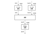
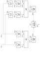
- FIG. 4 shows an example of a process for measuring the frequency characteristics of the impedance Z of the storage battery 6, which is performed by the data processing unit 26 of the process execution unit 21.
- the data processing unit 26 performs a Fourier transform, such as a fast Fourier transform, on the current time series data Ii1(t) for the pseudo-random pulse signal that is the input current Ii to the storage battery 6 (S101). This calculates current spectrum data (first current spectrum data) Ii1(f) that indicates the frequency characteristics for the pseudo-random pulse signal that is the input current Ii to the storage battery 6.
- a Fourier transform such as a fast Fourier transform
- the data processing unit 26 also performs a Fourier transform, such as a fast Fourier transform, on the voltage time series data Vm1(t) for the voltage Vm in a state in which the pseudo-random pulse signal is input to the storage battery (S102). This calculates voltage spectrum data (first voltage spectrum data) Vm1(f) that indicates the frequency characteristics for the voltage Vm, which is a voltage component equivalent to the fluctuating voltage of the storage battery 6.
- a Fourier transform such as a fast Fourier transform
- the current components at each of the many frequencies included in the measurement frequency range to be measured are shown for the pseudo-random pulse signal that is the input current Ii.
- the voltage spectrum data Vm1(f) the voltage components at each of the many frequencies included in the measurement frequency range to be measured are shown for the voltage Vm.
- the measurement frequency ranges in the current spectrum data Ii1(f) and the voltage spectrum data Vm1(f) correspond to the measurement frequency range in which the impedance Z is measured in measuring the frequency characteristics of the impedance Z of the storage battery 6.
- the measurement frequency ranges in the current spectrum data Ii1(f) and the voltage spectrum data Vm1(f) are included within the aforementioned specific frequency range in which the voltage components are not removed by the bandpass filter 35.
- the data processing unit 26 performs a calculation using the current spectrum data Ii1(f) and the voltage spectrum data Vm1(f) (S103) to calculate impedance spectrum data (first impedance spectrum data) Za1(f) indicating the frequency characteristics of the impedance Z of the storage battery 6.
- the impedance spectrum data Za1(f) is calculated, for example, by dividing the voltage spectrum data Vm1(f) by the current spectrum data Ii1(f).
- the impedance spectrum data Za1(f) indicates impedance components at each of a large number of frequencies included in the aforementioned measurement frequency range for the impedance Z of the storage battery 6. At frequencies at which impedance components are indicated in the impedance spectrum data Za1(f), the current component is indicated in the current spectrum data Ii1(f) and the voltage component is indicated in the voltage spectrum data Vm1(f).
- impedance spectrum data indicating the frequency characteristics of the impedance Z of the storage battery 6 may be calculated in the same manner as in Patent Document 3.
- the data processing unit 26 calculates the autocorrelation function of the current spectrum data Ii1(f) and calculates the cross-correlation function between the current spectrum data Ii1(f) and the voltage spectrum data Vm1(f). Then, the data processing unit 26 calculates the impedance spectrum data for the impedance Z of the storage battery 6 using the calculated autocorrelation function and cross-correlation function.
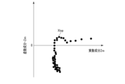
- the impedance spectrum data Za1(f), which is the measurement data measured as described above regarding the frequency characteristics of the impedance Z of the storage battery 6, can be shown in a complex impedance plot (Cole-Cole plot).
- Figure 5 shows an example of the impedance spectrum data Za1(f) regarding the frequency characteristics of the impedance Z of the storage battery 6 in the form of a complex impedance plot.
- the horizontal axis indicates the real component Zre of the impedance Z
- the vertical axis indicates the imaginary component -Zim of the impedance Z.
- the real and imaginary components of the impedance Z of the storage battery 6 are shown for each of the many frequencies included in the measurement frequency range.
- the distance from the origin is the absolute value (magnitude)
- the positive side of the real axis is set to 0, and the phase ⁇ of the impedance Z is defined. Therefore, the impedance spectrum data Za1(f) that can be shown in a complex impedance plot shows the relationship of the absolute value
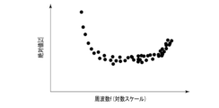
- FIG. 6 shows an example of the relationship between the absolute value
- FIG. 7 shows an example of the relationship between the phase ⁇ of the impedance Z of the storage battery 6 and frequency f, as shown in the impedance spectrum data Za1(f).
- the horizontal axis indicates the frequency f on a logarithmic scale.
- the vertical axis in FIG. 6 indicates the absolute value
- the vertical axis in FIG. 7 indicates the phase ⁇ . As shown in FIG.
- the impedance spectrum data Za1(f) indicates the absolute value
- the impedance spectrum data Za1(f) indicates the phase ⁇ of the impedance Z of the storage battery 6 for each of the many frequencies included in the measurement frequency range.
- the data processing unit 26 performs averaging processing on the impedance spectrum data Za1(f), which is measurement data of the frequency characteristics of the impedance Z of the storage battery 6 (S104). Then, averaging processing data (first averaging processing data) Zb1(f), which is impedance spectrum data obtained by averaging the impedance spectrum data Za1(f), is generated. Note that in another example, the averaging processing of S104 does not need to be performed.
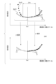
- FIG. 8 illustrates an example of averaging performed by the data processing unit 26 on the impedance spectrum data Za1(f), which is measurement data of the frequency characteristics of the impedance Z of the storage battery 6.
- the averaging is explained using a graph in which the horizontal axis indicates the frequency f on a logarithmic scale and the vertical axis indicates the absolute value
- the averaging process by the data processing unit 26 calculates one data point of the post-averaging data Zb1(f) from multiple data points in the impedance spectrum data Za1(f) that are close to each other in frequency f.
- the averaged data Zb1(f) generated by the averaging process shows the impedance Z of the storage battery 6, including the absolute value
- the number of frequencies at which the impedance Z is shown in the averaged data Zb1(f) is reduced compared to the number of frequencies at which the impedance Z is shown in the impedance spectrum data Za1(f).
- the number of data points shown in the averaged data Zb1(f) is reduced compared to the number of data points shown in the impedance spectrum data Za1(f).
- the data processing unit 26 performs averaging on the impedance spectrum data Za1(f), which is the measurement data of the frequency characteristics of the impedance Z of the storage battery 6, so that the data points after the averaging process are equally spaced on the logarithmic scale of frequency f. Furthermore, in the averaging process, the higher the frequency f, the greater the number of data points of the impedance spectrum data Za1(f) used to calculate one data point of the averaged data Zb1(f). In other words, in the data after the averaging process, the higher the frequency f, the more data points of the data before the averaging process are used to calculate the data.
- FIG. 9 shows another example of the process of measuring the frequency characteristics of the impedance Z of the storage battery 6, which is performed by the data processing unit 26 of the process execution unit 21, different from that of FIG. 4.
- the processes of S101 to S104 are performed, as in the example of FIG. 4. Therefore, as described above, the impedance spectrum data (first impedance spectrum data) Za1(f) is calculated as measurement data using the current time series data (first current time series data) Ii1(t) and the voltage time series data (first voltage time series data) Vm1(t), and the averaged data (first averaged data) Zb1(f) is calculated by averaging.
- the data processing unit 26 resamples the current time series data Ii1(t) for the pseudo-random pulse signal, which is the input current Ii to the storage battery 6 (S105).
- current time series data (second current time series data) Ii2(t) is calculated by resampling the current time series data Ii1(t).
- the data processing unit 26 also resamples the voltage time series data Vm1(t) for the voltage Vm in a state in which the pseudo-random pulse signal is input to the storage battery (S106).
- voltage time series data (second voltage time series data) Vm2(t) is calculated by resampling the voltage time series data Vm1(t).
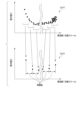
- FIG. 10 illustrates an example of resampling of the voltage time series data Vm1(t) performed by the data processing unit 26.
- resampling is explained using a graph in which the horizontal axis indicates time t and the vertical axis indicates voltage V.
- the analog signal Vm3(t) for the time change of the voltage Vm is shown by a dashed line in the graph described above.
- peaks A occur in both the high side region and the low side region with respect to the center of the fluctuation.
- the center of the fluctuation of the analog signal Vm3(t) is indicated by the center line C0.
- the A/D converter 33 samples the analog signal Vm3(t) at a predetermined sampling period to generate voltage time series data Vm1(t) as a digital signal in which the relationship of the voltage Vm with respect to time t is represented by data points ⁇ .
- the data points ⁇ represented by the voltage time series data Vm1(t) include data points ⁇ a that exist in the time range in which peak A occurs in the analog signal Vm3(t).
- the data processing unit 26 deletes data points ⁇ a that exist in the time range in which peak A occurs from the data points ⁇ represented by the voltage time series data Vm1(t).
- the data processing unit 26 performs an averaging process on the data points ⁇ other than the deleted data points ⁇ a.
- the data processing unit 26 resamples the voltage time series data Vm1(t) by performing an averaging process on data points ⁇ that exist outside the time range in which peak A occurs in the analog signal Vm3(t).
- the relationship of the voltage Vm to time t is represented by data points ⁇ in the resampled voltage time series data Vm2(t).
- the number of data points ⁇ in the resampled voltage time series data Vm2(t) is reduced compared to the number of data points ⁇ in the voltage time series data Vm1(t) before resampling.
- data points ⁇ a are not used in the averaging process performed in resampling, the effect of peak A that occurs in the analog signal Vm3(t) regarding the time change in voltage Vm is removed in the resampled voltage time series data Vm2(t).
- the A/D converter 33 samples the analog signal of the pseudo-random pulse signal at a predetermined sampling period to generate current time series data Ii1(t) as a digital signal whose data points indicate the relationship of the input current Ii against time t.
- the data points indicated by the current time series data Ii1(t) include data points that exist in the time range in which peaks occur in the analog signal of the pseudo-random pulse signal.
- Resampling of the current time series data Ii1(t) is performed in the same manner as resampling of the voltage time series data Vm1(t). That is, in resampling of the current time series data Ii1(t), the data processing unit 26 deletes data points that exist within the time range in which the above-mentioned peak occurs from the data points indicated by the current time series data Ii1(t). Then, the data processing unit 26 performs averaging processing on data points other than the deleted data points. That is, the data processing unit 26 resamples the current time series data Ii1(t) by performing averaging processing on data points that exist outside the time range in which the peak occurs in the analog signal for the pseudo-random pulse signal.
- the number of data points in the resampled current time series data Ii2(t) is reduced compared to the number of data points in the current time series data Ii1(t) before resampling. Furthermore, in the resampled current time series data Ii2(t), the effect of peaks that occur in the analog signal for the pseudo-random pulse signal is removed.
- the data processing unit 26 resamples the current time series data Ii1(t) based on the pseudo-random pulse signal and the voltage time series data Vm1(t) based on the time change in the voltage of the storage battery 6 so that the number of data points decreases.
- the current time series data Ii1(t) is resampled so that the influence of peaks occurring in the analog signal for the input current Ii to the storage battery 6 is removed by the resampling
- the voltage time series data Vm1(t) is resampled so that the influence of peaks A occurring in the analog signal for the voltage Vm related to the storage battery 6 is removed by the resampling.
- the data processing unit 26 performs a Fourier transform, such as a fast Fourier transform, on the current time series data (second current time series data) Ii2(t) obtained by resampling the current time series data Ii1(t) as described above (S107).
- the current time series data Ii2(t) is Fourier transformed in the same manner as the Fourier transform of the current time series data (first current time series data) Ii1(t) in S101.
- current spectrum data (second current spectrum data) Ii2(f) indicating the frequency characteristics of the pseudo-random pulse signal that is the input current Ii to the storage battery 6 is calculated separately from the current spectrum data Ii1(f).
- the data processing unit 26 also performs a Fourier transform, such as a fast Fourier transform, on the voltage time series data (second voltage time series data) Vm2(t) obtained by resampling the voltage time series data Vm1(t) as described above (S108).
- a Fourier transform such as a fast Fourier transform
- the voltage time series data Vm2(t) is Fourier transformed in the same manner as the Fourier transform of the voltage time series data (first voltage time series data) Vm1(t) in S102.
- voltage spectrum data (second voltage spectrum data) Vm2(f) indicating the frequency characteristics of the voltage Vm, which is a voltage component corresponding to the fluctuating voltage of the storage battery 6, is calculated separately from the voltage spectrum data Vm1(f).
- the data processing unit 26 performs a calculation using the current spectrum data Ii2(f) and the voltage spectrum data Vm2(f) (S109). At this time, the same calculation as in S103 is performed.
- impedance spectrum data (second impedance spectrum data) Za2(f) indicating the frequency characteristics of the impedance Z of the storage battery 6 is calculated separately from the impedance spectrum data Za1(f).
- the impedance spectrum data Za2(f) is calculated, for example, by dividing the voltage spectrum data Vm2(f) by the current spectrum data Ii2(f).
- the impedance spectrum data Za2(f) also indicates impedance components at each of the many frequencies included in the aforementioned measurement frequency range for the impedance Z of the storage battery 6.
- the data processing unit 26 performs averaging processing on the impedance spectrum data Za2(f), which is measurement data of the frequency characteristic of the impedance Z of the storage battery 6 (S110). At this time, the averaging processing is performed on the impedance spectrum data Za2(f) in the same manner as the averaging processing on the impedance spectrum data Za1(f) in S104. Therefore, the data processing unit 26 performs averaging processing on the impedance spectrum data Za2(f), which is measurement data of the frequency characteristic of the impedance of the storage battery 6, so that the data points after processing are equally spaced on the logarithmic scale of the frequency f.
- the averaged data (second averaged data) Zb2(f) which is the impedance spectrum data subjected to the averaging processing, is generated separately from the averaged data Zb1(f).
- the data processing unit 26 performs a data selection process on the averaged data Zb1(f) and Zb2(f) calculated as described above (S111).
- the selection process data Z0(f) is calculated as the final impedance spectrum data for the frequency characteristic of the impedance Z of the storage battery 6.
- FIG. 11 illustrates an example of data selection processing performed by the data processing unit 26 on two pieces of averaged data Zb1(f) and Zb2(f).
- the data selection processing is explained using a graph in which the horizontal axis indicates frequency f on a logarithmic scale and the vertical axis indicates the absolute value
- the data point ⁇ 1 in the averaged data (first averaged data) Zb1(f) is indicated by a filled circle
- the data point ⁇ 2 in the averaged data (second averaged data) Zb2(f) is indicated by a filled triangle.
- a reference frequency fref is specified in the data selection processing by the data processing unit 26, a reference frequency fref is specified.
- the reference frequency fref is included in the measurement frequency range in which the impedance Z of the storage battery 6 is measured.
- the data point ⁇ 1 in the averaged data Zb1(f) and the data point ⁇ 2 in the averaged data Zb2(f) are not shifted from each other, or are shifted very little.
- the data points ⁇ 1 and ⁇ 2 are shifted from each other.
- the reference frequency fref is included in the frequency range ⁇ fa.
- the measurement frequency range for measuring impedance Z is a range of 0.1 Hz or more and 5000 Hz or less, and the reference frequency fref is set to 2 Hz.
- the data processing unit 26 calculates the impedance indicated by the averaged data Zb1(f) as the impedance Z of the storage battery 6 for frequencies equal to or higher than the reference frequency fref. On the other hand, the data processing unit 26 calculates the impedance indicated by the averaged data Zb2(f) as the impedance Z of the storage battery 6 for frequencies lower than the reference frequency fref.
- the data point ⁇ 1 of the averaged data Zb1(f) is used for the impedance Z at frequencies equal to or higher than the reference frequency fref
- the data point ⁇ 2 of the averaged data Zb2(f) is used for the impedance Z at frequencies lower than the reference frequency fref.
- the data processing unit 26 performs the processes of S105 to S111 as described above. Therefore, in measuring the frequency characteristics of the impedance Z of the storage battery 6, the data processing unit 26 calculates the impedance Z of the storage battery 6 based on the current time series data (first current time series data) Ii1(t) and the voltage time series data (first voltage time series data) Vm1(t) for frequencies equal to or higher than the reference frequency fref.
- the data processing unit 26 calculates the impedance Z of the storage battery 6 based on the current time series data (second current time series data) Ii2(t) obtained by resampling the current time series data Ii1(t) and the voltage time series data (second voltage time series data) Vm2(t) obtained by resampling the voltage time series data Vm1(t) for frequencies lower than the reference frequency fref.
- the data processing unit 26 uses impedance spectrum data, which is the measurement result of the frequency characteristics of the impedance Z of the storage battery 6, to determine the state of the storage battery 6, including the deterioration state of the storage battery 6.
- impedance spectrum data is the measurement result of the frequency characteristics of the impedance Z of the storage battery 6, to determine the state of the storage battery 6, including the deterioration state of the storage battery 6.
- the state of the storage battery 6 is determined using the data Zb1(f) after the averaging process as the impedance spectrum data
- the state of the storage battery 6 is determined using the data Z0(f) after the selection process as the impedance spectrum data.
- the data processing unit 26 uses the measured impedance spectrum data and an equivalent circuit model of the storage battery 6 stored in the memory unit 22 to calculate the resistance components of the storage battery 6, such as the ohmic resistance of the storage battery 6 and the charge transfer resistance of the positive and negative electrodes of the storage battery 6.
- circuit constants electrical characteristic parameters
- circuit constants corresponding to the impedance components of the storage battery 6 are set.
- an arithmetic expression for calculating the impedance Z of the storage battery 6 from the circuit constants is shown.
- the aforementioned arithmetic expression shown in the equivalent circuit model can be, for example, an expression for calculating the real component and the imaginary component of the impedance Z of the storage battery 6 using the circuit constants and frequency, etc.
- the data processing unit 26 When calculating the resistance component of the storage battery 6, the data processing unit 26 performs a fitting calculation using an equivalent circuit model including the above-mentioned equivalent circuit, and impedance spectrum data that is the measurement result of the frequency characteristic of the impedance Z of the storage battery 6. At this time, the fitting calculation is performed using the circuit constants of the equivalent circuit of the storage battery 6 as variables, and the circuit constants (electrical characteristic parameters) that become the variables are calculated. In addition, in the fitting calculation, for example, the values of the circuit constants that become the variables are determined so that the difference between the calculation result of the impedance Z using the arithmetic expression shown in the equivalent circuit model and the measurement result of the impedance Z is as small as possible at each frequency at which the impedance Z is measured.
- the data processing unit 26 calculates the circuit constants of the equivalent circuit by fitting calculation as described above, and calculates the resistance component of the storage battery 6 based on the calculated circuit constants.
- the equivalent circuit of the storage battery and the circuit constants set in the equivalent circuit are shown in Patent Document 4 (JP Patent Publication 2017-106889).
- Patent Document 4 also shows a method of calculating the circuit constants of the equivalent circuit and the resistance component of the storage battery by performing fitting calculations using the measurement results of the impedance frequency characteristics of the storage battery and an equivalent circuit model of the storage battery.
- the frequency characteristics of the impedance Z of the storage battery 6 are measured as described above when the storage battery 6 is in each of the multiple target SOCs.
- the data processing unit 26 then calculates the resistance components, etc. of the storage battery 6 for each of the multiple target SOCs based on the impedance spectrum data, which is the measurement result of the frequency characteristics of the impedance Z.
- FIG. 12 shows an example of processing performed by the processing execution unit 21 including the input current adjustment unit 25 and the data processing unit 26 in determining the state of the storage battery 6.
- the processing in the example of FIG. 12 is performed in a state in which the storage battery 6 is being charged by the charging device 2.
- the frequency characteristics of the impedance Z of the storage battery 6 are measured for each of the target SOCs ⁇ 1 to ⁇ n, the number of targets being n (n is a natural number of 2 or more).
- the processing execution unit 21 determines the target SOCs ⁇ 1 to ⁇ n for which the frequency characteristics of the impedance Z are to be measured.
- the processing execution unit 21 In determining the target SOCs ⁇ 1 to ⁇ n, the processing execution unit 21 measures the real-time open circuit voltage (OCV) of the storage battery 6, and estimates the real-time SOC of the storage battery 6 based on the measurement result of the open circuit voltage and the relationship between the open circuit voltage and the SOC stored in the memory unit 22. Then, based on the estimated real-time SOC, the processing execution unit 21 determines the target number n of SOCs higher than the real-time SOC as the target SOCs ⁇ 1 to ⁇ n.
- the determined target SOCs ⁇ 1 to ⁇ n are the target SOCs ⁇ 1, ⁇ 2, ⁇ 3, ..., ⁇ n in order of decreasing SOC.
- the processing execution unit 21 may receive information regarding the SOC of the storage battery 6 from the charging device 2 or the storage device 3.
- the process execution unit 21 sends a command regarding the charge rate of the charging current Ic being output from the power supply circuit 11 to the control unit 12 of the charging device 2 (S121).
- the control unit 12 of the charging device 2 causes the power supply circuit 11 to output the charging current Ic at a charge rate corresponding to the command, and charges the storage battery 6.
- the process execution unit 21 determines whether the SOC of the storage battery 6 has reached the target SOC ⁇ 1 (S122). If the SOC has not reached the target SOC ⁇ 1 (S122-No), the process returns to S121, and the process execution unit 21 sequentially performs the processes from S121 onwards. Therefore, charging of the storage battery 6 continues until the SOC reaches the target SOC ⁇ 1.
- the processing execution unit 21 measures the real-time closed circuit voltage (CCV) of the storage battery 6 as the voltage Vd of the storage battery 6 based on the terminal voltage time series data Vd(t) for the voltage (terminal voltage) Vd of the storage battery 6. The processing execution unit 21 then calculates the real-time open circuit voltage of the storage battery 6 using the measurement result of the closed circuit voltage, the measurement result of the input current Ii to the storage battery 6, and the resistance component of the storage battery 6. At this time, the resistance value of the resistance component of the storage battery 6 used in the calculation is calculated based on the measurement result of the frequency characteristic of the impedance Z in the past judgment of the state of the storage battery 6 and the calculation result of the resistance component.
- CCV real-time closed circuit voltage
- the processing execution unit 21 estimates the real-time SOC of the storage battery 6 based on the calculated open circuit voltage of the storage battery 6 and the relationship between the open circuit voltage of the storage battery 6 and the SOC stored in the memory unit 22, and determines whether the estimated real-time SOC has reached the target SOC ⁇ 1.
- the process execution unit 21 may estimate the real-time SOC of the storage battery 6 by a so-called current integration method, instead of estimating the real-time SOC of the storage battery 6 based on the open circuit voltage of the storage battery 6 or the like.
- the process execution unit 21 may receive information related to the SOC of the storage battery 6 from the charging device 2 or the storage device 3, and estimate the real-time SOC of the storage battery 6 based on the received information.
- the input current adjustment unit 25 of the processing execution unit 21 controls the driving of the drive circuit 31 to generate a pseudo-random pulse signal, and inputs the generated pseudo-random pulse signal as an input current Ii to the storage battery 6. Then, the input current adjustment unit 25 controls the driving of the drive circuit 31 to adjust the pseudo-random pulse signal input to the storage battery 6 so that the measurement frequency range for measuring the impedance Z is the first measurement frequency range (S123).
- the first measurement frequency range is set to a relatively wide frequency range, and for example, a frequency range of 0.1 Hz or more and 5000 Hz or less is set as the first frequency range.
- the input current adjustment unit 25 adjusts the measurement frequency range for measuring the impedance Z of the storage battery 6 by adjusting the signal length Y of the pseudorandom pulse signal input to the storage battery 6, the pulse width w of one or more of the pulses p included in the pseudorandom pulse signal, and the number of pulses p included in the pseudorandom pulse signal.
- the input current adjustment unit 25 changes the measurement frequency range for measuring the impedance Z by changing the pulse width w of all pulses p included in the pseudorandom pulse signal at a uniform rate.
- the input current adjustment unit 25 changes the measurement frequency range for measuring the impedance Z by changing the number of pulses p included in the pseudorandom pulse signal.
- the reciprocal (1/Y) of the signal length Y of the pseudorandom pulse signal corresponds to the lower limit frequency of the measurement frequency range.
- the pulse pmin with the smallest pulse width w among the pulses p of the pseudorandom pulse signal is specified, and the pulse width wmin of the pulse pmin is specified.
- half the reciprocal of the pulse width wmin of the pulse pmin (1/(2 ⁇ wmin)) corresponds to the upper limit frequency of the measurement frequency range.
- the input current adjustment unit 25 determines whether the signal length Y of the pseudo-random pulse signal is longer than the reference signal length Yref (S124). If the signal length Y is longer than the reference signal length Yref (S124-Yes), the input current adjustment unit 25 reduces the charging rate of the charging current Ic being output from the power supply circuit 11 from the real-time rate by sending a command to the control unit 12 of the charging device 2 (S125). Then, with the charging rate of the charging current Ic reduced, the input current adjustment unit 25 inputs the pseudo-random pulse signal to the storage battery 6 as described above.
- the data processing unit 26 measures the frequency characteristic of the impedance Z of the storage battery 6 as described above (S126).
- impedance spectrum data such as the example of the averaging process data Zb1(f) in FIG. 4 and the example of the selection process data Z0(f) in FIG. 9 are obtained as the measurement result of the frequency characteristic of the impedance Z of the storage battery 6 at the target SOC ⁇ 1.
- the data processing unit 26 calculates the resistance component of the storage battery 6 as described above based on the impedance spectrum data that is the measurement result of the frequency characteristic of the impedance Z.
- the process of S126 is performed without performing the process of S125. That is, the frequency characteristic of the impedance Z of the storage battery 6 is measured and the resistance component of the storage battery 6, etc. are calculated without reducing the charge rate of the charging current Ic.
- the data processing unit 26 determines a characteristic frequency for the impedance Z of the storage battery 6 based on the impedance spectrum data, which is the measurement result of the frequency characteristics of the impedance Z of the storage battery 6 in the target SOC ⁇ 1 (S127).
- the characteristic frequency for the impedance Z includes, for example, a peak frequency.
- the frequency at the peak of the portion that is convex upward on the impedance locus i.e., the frequency at which the imaginary component of the impedance Z is minimal on the impedance locus, is the peak frequency.
- the frequency at the data point Xtop is the peak frequency.
- a setting parameter j is specified.
- the setting parameter j can be set to any one of natural numbers equal to or greater than 2 and equal to or less than n.
- the process execution unit 21 sets the setting parameter j to 2 (S128).
- the process execution unit 21 transmits a command regarding the charging rate of the charging current Ic to the control unit 12 of the charging device 2 (S129), and the control unit 12 of the charging device 2 charges the storage battery 6 at a charging rate corresponding to the command.
- the generation of the pseudo-random pulse signal by the drive circuit 31 is stopped, and all of the charging current Ic from the power supply circuit 11 is input to the storage battery 6 as the input current Ii.
- the process execution unit 21 determines whether the SOC of the storage battery 6 has reached the target SOC ⁇ j (S130). If the SOC has not reached the target SOC ⁇ j (S130-No), the process returns to S129, and the process execution unit 21 sequentially performs the processes from S129 onwards. Therefore, charging of the storage battery 6 continues until the SOC reaches the target SOC ⁇ j.
- the processing execution unit 21 calculates the real-time open circuit voltage of the storage battery 6 using the measurement result of the closed circuit voltage, the measurement result of the input current Ii to the storage battery 6, and the resistance component of the storage battery 6. At this time, the resistance value of the resistance component of the storage battery 6 used in the calculation is calculated based on the measurement result of the frequency characteristic of the impedance Z at the target SOC ⁇ 1 or the target SOC ⁇ j-1 and the calculation result of the resistance component.
- the processing execution unit 21 estimates the real-time SOC of the storage battery 6 based on the calculated open circuit voltage of the storage battery 6 and the relationship between the open circuit voltage of the storage battery 6 and the SOC stored in the memory unit 22, and determines whether the estimated real-time SOC has reached the target SOC ⁇ j.
- the process execution unit 21 may estimate the real-time SOC of the storage battery 6 by a so-called current integration method, instead of estimating the real-time SOC of the storage battery 6 based on the open circuit voltage of the storage battery 6 or the like.
- the process execution unit 21 may receive information related to the SOC of the storage battery 6 from the charging device 2 or the storage device 3, and estimate the real-time SOC of the storage battery 6 based on the received information.
- the input current adjustment unit 25 of the processing execution unit 21 controls the driving of the drive circuit 31 to generate a pseudo-random pulse signal, and inputs the generated pseudo-random pulse signal as an input current Ii to the storage battery 6. Then, the input current adjustment unit 25 controls the driving of the drive circuit 31 to adjust the pseudo-random pulse signal input to the storage battery 6 so that the measurement frequency range for measuring the impedance Z is the second measurement frequency range (S131).
- the input current adjustment unit 25 adjusts the signal length Y of the pseudo-random pulse signal input to the storage battery 6 and the pulse width w of one or more of the pulses p included in the pseudo-random pulse signal, thereby adjusting the measurement frequency range for measuring the impedance Z of the storage battery 6.
- the second measurement frequency range is set narrower than the first measurement frequency range.
- the second measurement frequency range includes the feature frequency determined in S127.
- the second frequency range is set to the peak frequency, which is the feature frequency, and a relatively narrow frequency range in its vicinity. Therefore, in measuring the frequency characteristics of the impedance Z of the storage battery 6 after determining the feature frequency, the input current adjustment unit 25 of the processing execution unit 21 narrows the measurement frequency range compared to before the feature frequency was determined, on the condition that the feature frequency is included in the measurement frequency range for measuring the impedance Z of the storage battery 6.
- the input current adjustment unit 25 determines whether the signal length Y of the pseudo-random pulse signal is longer than the reference signal length Yref (S132). If the signal length Y is longer than the reference signal length Yref (S132-Yes), the input current adjustment unit 25 reduces the charging rate of the charging current Ic being output from the power supply circuit 11 from the real-time rate by sending a command to the control unit 12 of the charging device 2 (S133). Then, with the charging rate of the charging current Ic reduced, the input current adjustment unit 25 inputs the pseudo-random pulse signal to the storage battery 6 as described above.
- the data processing unit 26 measures the frequency characteristics of the impedance Z of the storage battery 6 as described above (S134). As a result, impedance spectrum data is acquired as a measurement result of the frequency characteristics of the impedance Z of the storage battery 6 at the target SOC ⁇ j. The data processing unit 26 also calculates the resistance component of the storage battery 6 as described above based on the impedance spectrum data, which is the measurement result of the frequency characteristics of the impedance Z. If the signal length Y of the pseudo-random pulse signal is equal to or less than the reference signal length Yref (S132-No), the process of S133 is not performed and the process of S134 is performed. That is, the frequency characteristics of the impedance Z of the storage battery 6 are measured and the resistance component, etc. of the storage battery 6 are calculated without reducing the charge rate of the charging current Ic.
- the processing execution unit 21 stops the generation of the pseudo-random pulse signal by the drive circuit 31. Then, the processing execution unit 21 determines whether the measurement of the frequency characteristic of the impedance Z has been completed for all of the target SOCs ⁇ 2 to ⁇ n (S135). If the measurement of the frequency characteristic of the impedance Z has been completed for all of the target SOCs ⁇ 2 to ⁇ n (S135-Yes), the example process of FIG. 12, i.e., the process performed in determining the state of the storage battery 6, is completed.
- the process execution unit 21 increments the setting parameter j by 1 (S136). Then, the process returns to S129, and the processes from S129 onwards are performed sequentially. Therefore, the processes from S129 to S136 are repeated until the frequency characteristic of impedance Z has been measured for all of the target SOCs ⁇ 2 to ⁇ n. Note that by repeating the processes from S129 to S136, the frequency characteristic of impedance Z of the storage battery 6 is measured for the target SOCs ⁇ 2 to ⁇ n in ascending order of SOC, and the resistance component of the storage battery 6 is calculated.
- the impedance Z of the storage battery 6 is measured based on the pseudo-random pulse signal of the current input to the storage battery 6 and the time change in the voltage Vd of the storage battery 6 in a state in which the pseudo-random pulse signal of the current is input to the storage battery 6. Since the pseudo-random pulse signal is input to the storage battery 6 as the input current Ii, the current signal to be input to the storage battery 6 can be generated with a simple configuration compared to the case where the frequency characteristic of the impedance Z is measured by inputting a current signal whose current value changes periodically at each of a number of frequencies to the storage battery 6. Therefore, the impedance Z of the storage battery 6 can be measured with a simple configuration.
- the frequency characteristic of the impedance Z of the storage battery 6 can be measured in a short time compared to the case where the frequency characteristic of the impedance Z is measured by inputting a current signal whose current value changes periodically at each of a number of frequencies to the storage battery 6.
- a pseudo-random pulse signal of a current that changes between a first current value (e.g., I ⁇ -I ⁇ ) greater than zero and a second current value (e.g., I ⁇ ) greater than the first current value is input to the storage battery 6. Therefore, by inputting a pseudo-random pulse signal to the storage battery 6, it becomes possible to measure the impedance Z of the storage battery 6 in parallel with charging the storage battery 6. This improves the convenience of charging the storage battery 6 and measuring the impedance Z.
- the pseudo-random pulse signal to be input to the storage battery 6 in measuring the impedance Z is generated by shunting the charging current Ic output from the power supply circuit 11 of the charging device 2.
- This makes it possible to generate a pseudo-random pulse signal from the charging current Ic with a simple configuration, and makes it possible to miniaturize the configuration that generates the pseudo-random pulse signal from the charging current Ic, such as the drive circuit 31.
- the pseudo-random pulse signal is generated by shunting the charging current Ic, the impedance Z of the storage battery 6 is appropriately measured in parallel with the charging of the storage battery 6.
- the pseudo-random pulse signal has high resistance to noise. Therefore, even if the pseudo-random pulse signal is generated by shunting the charging current Ic, the frequency characteristics of the impedance Z of the storage battery 6 can be appropriately measured by inputting the generated pseudo-random pulse signal to the storage battery 6.
- the band pass filter 35 removes voltage components outside the specific frequency range, thereby reducing the voltage offset relative to 0V. Therefore, the time change of the voltage Vm with the voltage offset relative to 0V reduced is measured with high resolution by the A/D converter 33.
- the A/D converter 33 measures the voltage time series data Vm1(t) indicating the time change of the voltage Vm with high accuracy. Then, the impedance Z of the storage battery 6 is calculated using the voltage time series data Vm1(t) measured with high accuracy, thereby improving the accuracy of the measurement of the frequency characteristic of the impedance Z.
- the impedance spectrum data which is the measurement data of the frequency characteristics of the impedance Z of the storage battery 6, is averaged as described above so that the processed data points are equally spaced on the logarithmic scale of the frequency f.
- the impedance spectrum data Za1(f) is averaged, and in the example of FIG. 9, the impedance spectrum data Za1(f) and Za2(f) are averaged.
- the influence of noise on the impedance Z is reduced in the high frequency range.
- the accuracy of the analysis of the frequency characteristics of the impedance Z of the storage battery 6 is further improved.
- the current time series data (first current time series data) Ii1(t) based on the pseudorandom pulse signal and the voltage time series data (first voltage time series data) Vm1(t) based on the time change in the voltage Vd of the storage battery 6 are resampled to remove the influence of peaks that occur in the analog signal and to reduce the number of data points.
- the impedance Z of the storage battery 6 is calculated based on the current time series data Ii1(t) and the voltage time series data Vm1(t), and for frequencies lower than the reference frequency fref, the impedance Z of the storage battery 6 is calculated based on the current time series data (second current time series data) Ii2(t) obtained by resampling the current time series data Ii1(t) and the voltage time series data (second voltage time series data) Vm2(t) obtained by resampling the voltage time series data Vm1(t).
- the impedance Z calculated based on the current time series data Ii1(t) and the voltage time series data Vm1(t) before resampling tends to match the frequency characteristics of the impedance Z measured by inputting a current signal whose current value changes periodically at each of a number of frequencies to the storage battery 6.
- the impedance Z calculated based on the current time series data Ii2(t) and the voltage time series data Vm2(t) after resampling tends to match the frequency characteristics of the impedance Z measured by inputting a current signal whose current value changes periodically at each of a number of frequencies to the storage battery 6.
- the accuracy of the analysis is further improved by analyzing the frequency characteristics of the impedance Z of the storage battery 6 in the same manner as the example shown in FIG. 9, etc.
- the frequency characteristics of the impedance Z of the storage battery 6 are measured using a pseudo-random pulse signal for each of the multiple target SOCs ⁇ 1 to ⁇ n.
- a characteristic frequency for the impedance Z is then determined based on the measurement results of the frequency characteristics of the impedance Z for the target SOC ⁇ 1.
- the frequency range of the measurement of the frequency characteristics of the impedance Z for each of the target SOCs ⁇ 2 to ⁇ n is narrowed compared to the measurement of the frequency characteristics of the impedance Z for the target SOC ⁇ 1, provided that the characteristic frequency is included in the measurement frequency range for measuring the impedance Z of the storage battery 6. This shortens the measurement time and reduces the amount of data when measuring the frequency characteristics of the impedance Z for each of the target SOCs ⁇ 2 to ⁇ n.
- the measurement frequency range for measuring the impedance of the storage battery 6 is adjusted by adjusting the signal length Y of the pseudo-random pulse signal, the pulse width w of one or more of the pulses p included in the pseudo-random pulse signal, or the number of pulses p included in the pseudo-random pulse signal. Therefore, by adjusting the driving state of the drive circuit 30, for example by adjusting the switching operation of the switch 32, the measurement frequency range for measuring the impedance of the storage battery 6 can be easily adjusted.
- the charging rate of the charging current Ic output from the power supply circuit 11 to the storage battery 6 is reduced from the real-time rate based on the fact that the signal length Y of the pseudo-random pulse signal of the current input to the storage battery 6 is longer than the reference signal length Yref.
- the measurement device 5 is provided separately from the charging device 2 having the power supply circuit 11, and the storage device 3 having the storage battery 6. Therefore, it is possible to measure the impedance Z of the storage battery 6 using the measurement device 5 without changing the configuration of the charging device 2 and the storage device 3. Therefore, it is not necessary to provide a power supply for measuring the impedance Z separately from the power supply circuit 11 of the charging device 2.
- the measurement device 5 is separate from the charging device 2 including the power supply circuit 11 and the storage device 3 including the storage battery 6, but is not limited thereto.
- the measurement device 5 is built into the charging device 2.
- the impedance Z of the storage battery 6 is measured by inputting a pseudo-random pulse signal of a current that changes between a first current value larger than zero and a second current value larger than the first current value to the storage battery 6. Therefore, in this modified example, as in the above-mentioned embodiment, the impedance Z of the storage battery 6 can be measured with a simple configuration, and the convenience of charging the storage battery 6 and measuring the impedance Z is improved.
- a pseudo-random pulse signal is generated to be input to the storage battery 6 when measuring the impedance Z.
- the charging device 2 can be equipped with a high-performance computing device, server, communication module, or the like. This makes it possible to easily analyze and manage data in the charging device 2, and improves the accuracy of the data analysis.
- a measuring device 5 is built into the power storage device 3.
- the impedance Z of the storage battery 6 is measured by inputting a pseudo-random pulse signal of a current that changes between a first current value greater than zero and a second current value greater than the first current value to the storage battery 6. Therefore, in this modified example, as in the above-mentioned embodiment, the impedance Z of the storage battery 6 can be measured with a simple configuration, and the convenience of charging the storage battery 6 and measuring the impedance Z is improved.
- the measuring device 5 since the measuring device 5 is built into the power storage device 3, it is possible to measure the impedance Z of the storage battery 6 using the measuring device 5 built into the power storage device 3 without changing the configuration of the charging device 2. Therefore, there is no need to provide a power source for measuring the impedance Z separately from the power supply circuit 11 of the charging device 2.
- a pseudo-random pulse signal of a current that changes between a first current value greater than zero and a second current value greater than the first current value is input to the storage battery.
- the impedance of the storage battery is then measured based on the pseudo-random pulse signal of the current input to the storage battery and the change over time in the voltage of the storage battery while the pseudo-random pulse signal of the current is input to the storage battery.
Landscapes
- Physics & Mathematics (AREA)
- General Physics & Mathematics (AREA)
- Mathematical Physics (AREA)
- Charge And Discharge Circuits For Batteries Or The Like (AREA)
Abstract
Description
本発明の実施形態は、計測装置、蓄電システム及び計測方法に関する。 Embodiments of the present invention relate to a measuring device, a power storage system, and a measuring method.
蓄電池の劣化状態の診断等において、蓄電池のインピーダンスの周波数特性の計測が行われている。蓄電池のインピーダンスの周波数特性の計測では、例えば、周期的に電流値が変化する電流波形を複数の周波数のそれぞれで蓄電池に入力し、蓄電池に電流波形が入力されている状態での蓄電池の電圧の時間変化を計測する。そして、蓄電池に入力されている電流波形、及び、蓄電池の電圧の時間変化をフーリエ解析することにより、複数の周波数のそれぞれでの蓄電池のインピーダンスを計測し、蓄電池のインピーダンスの周波数特性を計測する。 When diagnosing the deterioration state of a storage battery, the frequency characteristics of the impedance of the battery are measured. In measuring the frequency characteristics of the impedance of the battery, for example, a current waveform whose current value changes periodically is input to the battery at each of multiple frequencies, and the time change in the voltage of the battery is measured while the current waveform is input to the battery. Then, by performing Fourier analysis on the current waveform input to the battery and the time change in the voltage of the battery, the impedance of the battery at each of multiple frequencies is measured, and the frequency characteristics of the impedance of the battery are measured.
蓄電池のインピーダンスの周波数特性の計測では、蓄電池に入力する電流を容易な構成で発生可能にする等して、容易な構成で蓄電池のインピーダンスを計測可能にすることが、求められている。また、蓄電池の充電と並行して蓄電池のインピーダンスを計測可能にする等して、蓄電池の充電及びインピーダンスの計測における利便性を向上させることが、求められている。 In measuring the frequency characteristics of the impedance of a storage battery, it is required to be able to measure the impedance of the storage battery with a simple configuration, for example by making it possible to generate the current input to the storage battery with a simple configuration. In addition, it is required to improve the convenience of charging the storage battery and measuring the impedance, for example by making it possible to measure the impedance of the storage battery in parallel with charging the storage battery.
本発明が解決しようとする課題は、容易な構成で蓄電池のインピーダンスを計測可能にし、蓄電池の充電及びインピーダンスの計測における利便性を向上させる計測装置、蓄電システム及び計測方法を提供することにある。 The problem that the present invention aims to solve is to provide a measurement device, a power storage system, and a measurement method that enable the impedance of a storage battery to be measured with a simple configuration and improves the convenience of charging the storage battery and measuring its impedance.
実施形態によれば、計測装置は、処理回路を備え、処理回路は、ゼロより大きい第1の電流値と第1の電流値より大きい第2の電流値との間で変化する電流の疑似ランダムパルス信号を蓄電池に入力させる。処理回路は、蓄電池に入力される電流の疑似ランダムパルス信号、及び、電流の疑似ランダムパルス信号が蓄電池に入力されている状態での蓄電池の電圧の時間変化に基づいて、蓄電池のインピーダンスを計測する。 According to an embodiment, the measurement device includes a processing circuit that inputs a pseudo-random pulse signal of current, which changes between a first current value greater than zero and a second current value greater than the first current value, to the storage battery. The processing circuit measures the impedance of the storage battery based on the pseudo-random pulse signal of current input to the storage battery and the change over time in the voltage of the storage battery while the pseudo-random pulse signal of current is input to the storage battery.
以下、実施形態について図面を参照して、説明する。 The following describes the embodiment with reference to the drawings.
(第1の実施形態)
まず、実施形態の一例として、第1の実施形態について説明する。図1は、第1の実施形態に係る蓄電システム1の一例を示す。図1に示すように、蓄電システム1は、充電器等の充電装置2、蓄電装置3及び計測装置5を備え、蓄電装置3は、蓄電池6を備える。図1の一例では、充電装置2、蓄電装置3及び計測装置5は、互いに対して別体で設けられる。蓄電装置3は、例えば、電池搭載機器(図示しない)に搭載される。蓄電装置3が搭載される電池搭載機器としては、AGV(Automatic Guided Vehicle)等の工場用の搬送車、定置用電源装置、スマートフォン、電気自動車等の車両、ロボット及びドローン等が挙げられる。
First Embodiment
First, a first embodiment will be described as an example of an embodiment. FIG. 1 shows an example of a
蓄電装置3に搭載される蓄電池6は、例えば、リチウムイオン二次電池等の二次電池である。蓄電池6は、単セル(単電池)から形成されてもよく、複数の単セルを電気的に接続することにより形成される電池モジュール又はセルブロックであってもよい。蓄電池6が複数の単セルから形成される場合、蓄電池6において、複数の単セルが電気的に直列に接続されてもよく、複数の単セルが電気的に並列に接続されてもよい。また、蓄電池6において、複数の単セルが直列に接続される直列接続構造、及び、複数の単セルが並列に接続される並列接続構造の両方が形成されてもよい。また、蓄電池6は、複数の電池モジュールが電気的に接続される電池ストリング及び電池アレイのいずれかであってもよい。
The
充電装置2は、蓄電池6の充電において、蓄電池6に電力を供給する。充電装置2は、電源回路11、制御回路等の制御部12、及び、記憶部13を備える。蓄電池6の充電においては、電源回路11から蓄電池6へ充電電流Icが出力される。図1の一例では、電源回路11から蓄電池6への充電電流Icの供給経路は、計測装置5を通って形成される。
The
充電装置2は、プロセッサ又は集積回路等、及び、メモリ等の記憶媒体を備える。充電装置2では、プロセッサ又は集積回路等は、CPU(Central Processing Unit)、ASIC(Application Specific Integrated Circuit)、マイコン、FPGA(Field Programmable Gate Array)及びDSP(Digital Signal Processor)等のいずれかを含む。充電装置2には、プロセッサ等は、1つのみ設けられてもよく、複数設けられてもよい。また、充電装置2には、記憶媒体は、1つのみ設けられてもよく、複数設けられてもよい。充電装置2では、プロセッサ又は集積回路等は、例えば、記憶媒体に記憶されたプログラムを実行することにより、処理を行う。また、充電装置2では、プロセッサ等によって、制御部12の処理が行われ、記憶媒体が記憶部13として機能する。
The
蓄電池6の充電では、制御部12は、電源回路11の駆動を制御することにより、蓄電池6への電力の供給を制御する。そして、制御部12は、電源回路11の駆動を制御することにより、電源回路11から蓄電池6へ出力される充電電流Icの充電レート等を調整する。
When charging the
図1の一例では、計測装置5は、電流検出回路15及び電圧検出回路16を備える。蓄電池6を充電している状態等においては、電流検出回路15は、蓄電池6に流れる電流である蓄電池6への入力電流Iiを検出し、電圧検出回路16は、蓄電池6に印加される電圧Vdを検出する。電流検出回路15は、例えば、シャント抵抗を備え、シャント抵抗に印加される電圧に基づいて、蓄電池6の電流(入力電流Ii)を検出する。また、電圧検出回路16は、例えば、蓄電池6の端子間電圧を、蓄電池6の電圧Vdとして検出する。なお、ある一例では、電流検出回路15及び電圧検出回路16は、蓄電装置3に設けられてもよい。
1, the
計測装置5は、蓄電池6のインピーダンスZを計測する。図1の一例では、電源回路11から蓄電池6へ出力される充電電流Icによって蓄電池6が充電されている状態において、計測装置5は、蓄電池6のインピーダンスZの計測を行う。計測装置5は、処理回路等の処理実行部21、及び、記憶部22を備え、処理実行部21は、入力電流調整部25及びデータ処理部26を備える。入力電流調整部25及びデータ処理部26のそれぞれは、処理実行部21によって行われる処理の一部を実行する。
The
計測装置5は、プロセッサ又は集積回路等、及び、メモリ等の記憶媒体を備える。計測装置5では、プロセッサ又は集積回路等は、CPU、ASIC、マイコン、FPGA及びDSP等のいずれかを含む。計測装置5には、プロセッサ等は、1つのみ設けられてもよく、複数設けられてもよい。また、計測装置5には、記憶媒体は、1つのみ設けられてもよく、複数設けられてもよい。計測装置5では、プロセッサ又は集積回路等は、例えば、記憶媒体に記憶されたプログラムを実行することにより、処理を行う。また、計測装置5では、プロセッサ等によって、処理実行部21の処理が行われ、記憶媒体が記憶部22として機能する。入力電流調整部25及びデータ処理部26を含む処理実行部21は、例えば、記憶部22に記憶される計測プログラムを実行することにより、後述する処理を行う。
The
また、計測装置5は、駆動回路31を備え、図1の一例では、駆動回路31は、スイッチ32及び抵抗34を備える。駆動回路31は、充電装置2の電源回路11から蓄電装置3の蓄電池6への充電電流Icの供給経路に、形成される。処理実行部21の入力電流調整部25は、電源回路11から蓄電池6に充電電流Icが出力されている状態において、駆動回路31の駆動を制御し、例えば、スイッチ32のオンオフを制御する。これにより、蓄電池6に入力される入力電流Iiが、調整及び制御される。
The measuring
図1の一例では、駆動回路31のスイッチ32のオフ状態において、電源回路11から出力された充電電流Icの全てが、蓄電池6に入力される。この際、駆動回路31の抵抗34には、電流が流れない。一方、駆動回路31のスイッチ32のオン状態では、電源回路11から出力された充電電流Icの一部が駆動回路31において分流され、充電電流Icから分流された電流が、抵抗34を流れる。抵抗34を流れる電流は、蓄電池6に供給されないバイパス電流Ibとなる。そして、充電電流Icにおいてバイパス電流Ibとして分流されない残りの一部が、蓄電池6に入力される入力電流Iiとなる。
In the example shown in FIG. 1, when the
入力電流調整部25は、スイッチ32のスイッチング動作、すなわち、スイッチ32のオンオフを制御することにより、駆動回路31での充電電流Icの分流を制御する。そして、入力電流調整部25は、駆動回路31での充電電流Icの分流を制御することにより、電流の疑似ランダムパルス信号を発生させ、発生させた電流の疑似ランダムパルス信号を、蓄電池6への入力電流Iiとして蓄電池6へ入力させる。したがって、本実施形態では、処理回路等の処理実行部21は、蓄電池6のインピーダンスZの計測において、電源回路11から蓄電池6に出力された充電電流Icを分流させることにより、電流の疑似ランダムパルス信号を、蓄電池6への入力電流Iiとして発生させる。なお、疑似ランダムパルス信号は、例えばM系列の信号を用いる。
The input
図2は、電源回路11から出力される充電電流Ic、蓄電池6に入力される入力電流Iiである電流の疑似ランダムパルス信号、及び、充電電流Icから分流されるバイパス電流Ibのそれぞれの時間変化の一例を示す。図2では、横軸に時間tを示し、縦軸に電流Iを示す。図2の一例では、充電電流Icは、電流値Iαで経時的に一定又は略一定に保たれる。そして、駆動回路31のスイッチ32のオフ状態では、充電電流Icが分流されず、疑似ランダムパルス信号(入力電流Ii)は電流値Iαとなり、バイパス電流Ibは電流値0となる。一方、駆動回路31のスイッチ32のオン状態では、電流値Iβに相当する電流がバイパス電流Ibとして充電電流Icから分流され、疑似ランダムパルス信号(入力電流Ii)は電流値Iα-Iβとなる。図2の一例では、電流値Iβは、電流値Iαの半分値より小さい値であり、例えば、電流値Iαの10%程度の値である。
2 shows an example of the change over time of the charging current Ic output from the
前述のように充電電流Ic、疑似ランダムパルス信号(入力電流Ii)及びバイパス電流Ibのそれぞれが時間的に変化するため、図2の一例では、バイパス電流Ibは、ゼロと電流値Iβとの間で、時間的に変化する。そして、疑似ランダムパルス信号は、ゼロより大きい電流値(第1の電流値)Iα-Iβと電流値Iα-Iβより大きい電流値(第2の電流値)Iαとの間で、時間的に変化する。 As described above, the charging current Ic, the pseudo-random pulse signal (input current Ii), and the bypass current Ib each change over time, so in the example of FIG. 2, the bypass current Ib changes over time between zero and a current value Iβ. And the pseudo-random pulse signal changes over time between a current value (first current value) Iα-Iβ that is greater than zero and a current value (second current value) Iα that is greater than the current value Iα-Iβ.
また、疑似ランダムパルス信号には、複数のパルスpが含まれ、複数のパルスpのそれぞれでは、疑似ランダムパルス信号の電流値は、電流値Iαより低くなる。蓄電池6への入力電流Iiとなる疑似ランダムパルス信号では、複数のパルスpのそれぞれについてパルス幅wが規定され、複数のパルスpの少なくとも1つは、他のパルスpとはパルス幅wが異なる。また、疑似ランダムパルス信号のパルスpの中でパルス幅wが最も小さいパルスpminを規定し、パルスpminのパルス幅wminを規定する。M系列の信号の場合、複数のパルスpのそれぞれでは、パルス幅wは、パルスpminのパルス幅wminの整数倍の幅となる。また、疑似ランダムパルス信号では、信号長Yが規定される。ある一例では、疑似ランダムパルス信号の信号長Yは、スイッチ32のスイッチング動作の開始時点から終了時点までの時間に相当する。
The pseudorandom pulse signal includes a plurality of pulses p, and the current value of each of the plurality of pulses p is lower than the current value Iα. In the pseudorandom pulse signal that becomes the input current Ii to the
蓄電池6に、電流の疑似ランダムパルス信号が入力電流Iiとして入力されている状態では、電流検出回路15は、電流の疑似ランダムパルス信号を検出し、電圧検出回路16は、蓄電池6の電圧の時間変化を検出する。また、計測装置5は、A/Dコンバータ33及びバンドパスフィルタ(BPF)35を備える。A/Dコンバータ33には、電流検出回路15及び電圧検出回路16のそれぞれでの検出結果を示すアナログ信号が、入力される。
When a pseudo-random pulse signal of current is input to the
A/Dコンバータ33は、電流検出回路15での検出結果を示すアナログ信号、すなわち、蓄電池6に入力される入力電流Iiの検出結果を示すアナログ信号を、デジタル信号に変換する。また、A/Dコンバータ33は、電圧検出回路16での検出結果を示すアナログ信号、すなわち、蓄電池6の電圧(端子間電圧)Vdの時間変化を示すアナログ信号を、デジタル信号に変換する。A/Dコンバータ33は、所定のサンプリング周期で、サンプリングを行い、アナログ信号をデジタル信号に変換する。
The A/
また、A/Dコンバータ33には、電圧検出回路16での検出結果を示すアナログ信号が、前述のように直接的に入力されるとともに、電圧検出回路16での検出結果を示すアナログ信号が、バンドパスフィルタ35を通して入力される。バンドパスフィルタ35は、蓄電池6の電圧(端子間電圧)Vdの時間変化を示すアナログ信号において、特定周波数範囲の電圧成分のみを抽出し、特定周波数範囲の範囲外の電圧成分を除去する。なお、特定周波数範囲には、0Hzは含まれず、ある一例では、特定周波数範囲は、0.1Hz以上かつ5000Hz以下の周波数範囲となる。このため、バンドパスフィルタ35によって、電圧検出回路16での検出結果を示すアナログ信号から、0Hzの電圧成分、すなわち、直流に起因する電圧成分が除去される。電圧Vdの時間変化を示すアナログ信号において、直流に起因する電圧成分が除去されることにより、アナログ信号において、0Vに対する電圧オフセットが減少し、変動の中心が0Vに近づく。
The analog signal indicating the detection result of the
図3は、蓄電池6に電流の疑似ランダムパルス信号が入力電流Iiとして入力されている状態での蓄電池6の電圧(端子間電圧)Vdの時間変化を示すアナログ信号、及び、その電圧Vdの時間変化を示すアナログ信号をバンドパスフィルタ35によって処理した後の電圧Vmについてのアナログ信号の一例を示す。図3では、横軸に時間tを示し、縦軸に電圧Vを示す。
Figure 3 shows an example of an analog signal indicating the time change in voltage (terminal voltage) Vd of the
図3の一例では、電圧Vdの時間変化を示すアナログ信号において、電圧Vdは、電圧値Vαを中心として変動し、0Vに対して電圧値Vαに相当する電圧オフセットを有する。一方、電圧Vmの時間変化を示すアナログ信号では、電圧Vmは、電圧値Vαより0Vに近い電圧値Vβを中心として変動し、0Vに対して電圧値Vβに相当する電圧オフセットを有する。このため、電圧Vmの時間変化を示すアナログ信号では、電圧Vdの時間変化を示すアナログ信号に比べて、変動の中心が0Vに近づき、0Vに対する電圧オフセットが減少する。ある一例では、電圧Vmの時間変化を示すアナログ信号において、電圧Vdの時間変化を示すアナログ信号に比べて、蓄電池6の開回路電圧に相当する減少量だけ、0Vに対する電圧オフセットが減少する。なお、電圧Vmの時間変化を示すアナログ信号の変動の中心は、0V又は0Vに近い電圧値となる。このため、電圧Vmは、蓄電池6の電圧(端子間電圧)Vdの変動電圧に相当する電圧成分となる。
3, in an analog signal showing the time change of the voltage Vd, the voltage Vd fluctuates around a voltage value Vα and has a voltage offset corresponding to the voltage value Vα with respect to 0V. On the other hand, in an analog signal showing the time change of the voltage Vm, the voltage Vm fluctuates around a voltage value Vβ that is closer to 0V than the voltage value Vα and has a voltage offset corresponding to the voltage value Vβ with respect to 0V. Therefore, in the analog signal showing the time change of the voltage Vm, the center of the fluctuation is closer to 0V and the voltage offset with respect to 0V is reduced compared to the analog signal showing the time change of the voltage Vd. In one example, in the analog signal showing the time change of the voltage Vm, the voltage offset with respect to 0V is reduced by an amount equivalent to the open circuit voltage of the
A/Dコンバータ33は、バンドパスフィルタ35によって0Vに対する電圧オフセットが減少した電圧Vmのアナログ信号を、デジタル信号に変換する。そして、A/Dコンバータ33によって変換された3種類のデジタル信号は、処理実行部21のデータ処理部26に入力される。このため、処理実行部21には、蓄電池6に入力される入力電流Iiについてのデジタル信号、蓄電池6の電圧(端子間電圧)Vdについてのデジタル信号、及び、0Vに対する電圧オフセットを減少させた電圧Vmについてのデジタル信号が、入力される。なお、蓄電池6に電流の疑似ランダムパルス信号が入力されている状態では、疑似ランダムパルス信号についてのデジタル信号が、蓄電池6への入力電流Iiについてのデジタル信号として、処理実行部21に入力される。
The A/
ここで、電流の疑似ランダムパルス信号が入力電流Iiとして蓄電池6に入力されている状態において、疑似ランダムパルス信号についてのデジタル信号によって示されるデータを、電流時系列データ(第1の電流時系列データ)Ii1(t)とし、蓄電池6の電圧(端子間電圧)Vdについてのデジタル信号によって示されるデータを、端子間電圧時系列データVd(t)とし、0Vに対する電圧オフセットを減少させた電圧Vmについてのデジタル信号によって示されるデータを、電圧時系列データ(第1の電圧時系列データ)Vm1(t)とする。電流時系列データIi1(t)は、入力電流Iiとして蓄電池6に入力される疑似ランダムパルス信号に基づくデータとなり、端子間電圧時系列データVd(t)及び電圧時系列データVm1(t)は、疑似ランダムパルス信号が蓄電池6に入力されている状態での蓄電池6の電圧の時間変化に基づくデータとなる。
Here, in a state where a pseudo-random pulse signal of current is input to the
処理実行部(処理回路)21のデータ処理部26は、電流時系列データIi1(t)及び電圧時系列データVm1(t)を用いて、蓄電池6のインピーダンスZの周波数特性を計測する。したがって、蓄電池6に入力される電流の疑似ランダムパルス信号、及び、電流の疑似ランダムパルス信号が蓄電池6に入力されている状態での蓄電池6の電圧の時間変化に基づいて、蓄電池6のインピーダンスZ、及び、蓄電池6のインピーダンスZの周波数特性が計測される。
The
図4は、処理実行部21のデータ処理部26によって行われる、蓄電池6のインピーダンスZの周波数特性を計測する処理の一例を示す。図4の一例では、データ処理部26は、蓄電池6への入力電流Iiである疑似ランダムパルス信号についての電流時系列データIi1(t)を、高速フーリエ変換等によってフーリエ変換する(S101)。これにより、蓄電池6への入力電流Iiである疑似ランダムパルス信号についての周波数特性を示す電流スペクトルデータ(第1の電流スペクトルデータ)Ii1(f)が、算出される。また、データ処理部26は、疑似ランダムパルス信号が蓄電池に入力されている状態での電圧Vmについての電圧時系列データVm1(t)を、高速フーリエ変換等によってフーリエ変換する(S102)。これにより、蓄電池6の変動電圧に相当する電圧成分である電圧Vmについての周波数特性を示す電圧スペクトルデータ(第1の電圧スペクトルデータ)Vm1(f)が、算出される。
4 shows an example of a process for measuring the frequency characteristics of the impedance Z of the
電流スペクトルデータIi1(f)では、入力電流Iiである疑似ランダムパルス信号について、計測対象となる計測周波数範囲に含まれる多数の周波数のそれぞれにおける電流成分が、示される。そして、電圧スペクトルデータVm1(f)では、電圧Vmについて、計測対象となる計測周波数範囲に含まれる多数の周波数のそれぞれにおける電圧成分が、示される。電流スペクトルデータIi1(f)及び電圧スペクトルデータVm1(f)での計測周波数範囲は、蓄電池6のインピーダンスZの周波数特性の計測においてインピーダンスZを計測する計測周波数範囲に相当する。また、電流スペクトルデータIi1(f)及び電圧スペクトルデータVm1(f)での計測周波数範囲は、バンドパスフィルタ35によって電圧成分が除去されない前述の特定周波数範囲の範囲内に、含まれる。
In the current spectrum data Ii1(f), the current components at each of the many frequencies included in the measurement frequency range to be measured are shown for the pseudo-random pulse signal that is the input current Ii. And in the voltage spectrum data Vm1(f), the voltage components at each of the many frequencies included in the measurement frequency range to be measured are shown for the voltage Vm. The measurement frequency ranges in the current spectrum data Ii1(f) and the voltage spectrum data Vm1(f) correspond to the measurement frequency range in which the impedance Z is measured in measuring the frequency characteristics of the impedance Z of the
そして、データ処理部26は、電流スペクトルデータIi1(f)及び電圧スペクトルデータVm1(f)を用いて演算を行い(S103)、蓄電池6のインピーダンスZの周波数特性を示すインピーダンススペクトルデータ(第1のインピーダンススペクトルデータ)Za1(f)を、算出する。インピーダンススペクトルデータZa1(f)は、例えば、電圧スペクトルデータVm1(f)を電流スペクトルデータIi1(f)で除算することにより、算出される。インピーダンススペクトルデータZa1(f)では、蓄電池6のインピーダンスZについて、前述の計測周波数範囲に含まれる多数の周波数のそれぞれにおけるインピーダンス成分が、示される。インピーダンススペクトルデータZa1(f)においてインピーダンス成分が示される周波数では、電流スペクトルデータIi1(f)において電流成分が示されるとともに、電圧スペクトルデータVm1(f)において電圧成分が示される。
Then, the
なお、蓄電池の電流についての電流時系列データ、及び、蓄電池の電圧についての電圧時系列データを用いて、蓄電池のインピーダンスについてのインピーダンススペクトルデータを算出する方法は、特許文献3(日本国特開2014-126532号公報)に示される。実施形態等では、特許文献3と同様にして、蓄電池6のインピーダンスZの周波数特性を示すインピーダンススペクトルデータを算出してもよい。この場合、データ処理部26は、電流スペクトルデータIi1(f)の自己相関関数を算出するとともに、電流スペクトルデータIi1(f)と電圧スペクトルデータVm1(f)との相互相関関数を算出する。そして、データ処理部26は、算出した自己相関関数及び相互相関関数を用いて、蓄電池6のインピーダンスZについてのインピーダンススペクトルデータを算出する。
Note that a method for calculating impedance spectrum data for the impedance of a storage battery using current time series data for the current of the storage battery and voltage time series data for the voltage of the storage battery is shown in Patent Document 3 (JP Patent Publication No. 2014-126532). In the embodiment, impedance spectrum data indicating the frequency characteristics of the impedance Z of the
蓄電池6のインピーダンスZの周波数特性について前述のようにして計測した計測データであるインピーダンススペクトルデータZa1(f)は、複素インピーダンスプロット(Cole-Coleプロット)で示すことが可能である。図5は、蓄電池6のインピーダンスZの周波数特性についてのインピーダンススペクトルデータZa1(f)の一例を、複素インピーダンスプロットで示す。図5に示すように、複素インピーダンスプロットでは、横軸がインピーダンスZの実数成分Zreを示し、縦軸がインピーダンスZの虚数成分-Zimを示す。そして、図5の一例では、計測周波数範囲に含まれる多数の周波数のそれぞれについて、蓄電池6のインピーダンスZの実数成分及び虚数成分が示される。
The impedance spectrum data Za1(f), which is the measurement data measured as described above regarding the frequency characteristics of the impedance Z of the
複素インピーダンスプロットでは、原点からの距離が、インピーダンスZの絶対値(大きさ)|Z|となる。また、複素インピーダンスプロットでは、実数軸の正側を0として、インピーダンスZの位相θが規定される。このため、複素インピーダンスプロットで示すことが可能なインピーダンススペクトルデータZa1(f)では、周波数fに対する蓄電池6のインピーダンスZの絶対値|Z|の関係が示されるとともに、周波数fに対する蓄電池6のインピーダンスZの位相θの関係が示される。
In a complex impedance plot, the distance from the origin is the absolute value (magnitude) |Z| of the impedance Z. Also, in a complex impedance plot, the positive side of the real axis is set to 0, and the phase θ of the impedance Z is defined. Therefore, the impedance spectrum data Za1(f) that can be shown in a complex impedance plot shows the relationship of the absolute value |Z| of the impedance Z of the
図6は、蓄電池6のインピーダンスの周波数特性についてのインピーダンススペクトルデータZa1(f)で示される、周波数fに対する蓄電池6のインピーダンスZの絶対値|Z|の関係の一例を示し、図7は、インピーダンススペクトルデータZa1(f)で示される、周波数fに対する蓄電池6のインピーダンスZの位相θの関係の一例を示す。図6及び図7では、横軸が周波数fを対数スケールで示す。そして、図6の縦軸が絶対値|Z|を示し、図7の縦軸が位相θを示す。図6に示すように、インピーダンススペクトルデータZa1(f)では、計測周波数範囲に含まれる多数の周波数のそれぞれについて、蓄電池6のインピーダンスZの絶対値|Z|が示される。そして、図7に示すように、インピーダンススペクトルデータZa1(f)では、計測周波数範囲に含まれる多数の周波数のそれぞれについて、蓄電池6のインピーダンスZの位相θが示される。
FIG. 6 shows an example of the relationship between the absolute value |Z| of the impedance Z of the
また、図4の一例では、データ処理部26は、蓄電池6のインピーダンスZの周波数特性の計測データであるインピーダンススペクトルデータZa1(f)に対して、平均化処理を行う(S104)。そして、インピーダンススペクトルデータZa1(f)に対して平均化処理を行ったインピーダンススペクトルデータである平均化処理後データ(第1の平均化処理後データ)Zb1(f)が、生成される。なお、別のある一例では、S104の平均化処理は、行われなくてもよい。
In the example of FIG. 4, the
図8は、データ処理部26によって、蓄電池6のインピーダンスZの周波数特性の計測データであるインピーダンススペクトルデータZa1(f)に対して行われる、平均化処理の一例を説明する。図8では、横軸が周波数fを対数スケールで示し、かつ、縦軸が蓄電池6のインピーダンスZの絶対値|Z|を示すグラフを用いて、平均化処理について説明する。図8に示すように、データ処理部26による平均化処理によって、インピーダンススペクトルデータZa1(f)において互いに対して周波数fが近い複数のデータ点から、平均化処理後データZb1(f)の1つのデータ点が、算出される。
FIG. 8 illustrates an example of averaging performed by the
平均化処理によって生成された平均化処理後データZb1(f)では、計測周波数範囲に含まれる複数の周波数のそれぞれについて、絶対値|Z|及び位相θを含む蓄電池6のインピーダンスZが示される。ただし、平均化処理後データZb1(f)においてインピーダンスZが示される周波数の数は、インピーダンススペクトルデータZa1(f)においてインピーダンスZが示される周波数の数に比べて、減少する。すなわち、平均化処理後データZb1(f)において示されるデータ点の数は、インピーダンススペクトルデータZa1(f)において示されるデータ点の数に比べて、減少する。
The averaged data Zb1(f) generated by the averaging process shows the impedance Z of the
平均化処理によって生成された平均化処理後データZb1(f)では、複数のデータ点は、周波数fの対数スケールにおいて等間隔になる。したがって、データ処理部26は、周波数fの対数スケールにおいて処理後のデータ点が等間隔になる状態に、蓄電池6のインピーダンスZの周波数特性の計測データであるインピーダンススペクトルデータZa1(f)に対して、平均化処理を行う。また、平均化処理では、周波数fが高くなるほど、平均化処理後データZb1(f)の1つのデータ点の算出に用いられるインピーダンススペクトルデータZa1(f)のデータ点の数が、多い。すなわち、平均化処理の処理後のデータでは、周波数fが高いデータ点ほど、平均化処理の処理前のデータの多くのデータ点を用いて算出される。
In the averaged data Zb1(f) generated by the averaging process, multiple data points are equally spaced on the logarithmic scale of frequency f. Therefore, the
図9は、処理実行部21のデータ処理部26によって行われる、蓄電池6のインピーダンスZの周波数特性を計測する処理の図4とは別の一例を示す。図9の一例でも、図4の一例と同様に、S101~S104の処理が行われる。このため、前述したように、電流時系列データ(第1の電流時系列データ)Ii1(t)及び電圧時系列データ(第1の電圧時系列データ)Vm1(t)を用いて、インピーダンススペクトルデータ(第1のインピーダンススペクトルデータ)Za1(f)が計測データとして算出され、平均化処理によって平均化処理後データ(第1の平均化処理後データ)Zb1(f)が算出される。
FIG. 9 shows another example of the process of measuring the frequency characteristics of the impedance Z of the
ただし、図9の一例では、データ処理部26は、蓄電池6への入力電流Iiである疑似ランダムパルス信号についての電流時系列データIi1(t)に対して、リサンプリングを行う(S105)。これにより、電流時系列データIi1(t)をリサンプリングした電流時系列データ(第2の電流時系列データ)Ii2(t)が、算出される。また、データ処理部26は、疑似ランダムパルス信号が蓄電池に入力されている状態での電圧Vmについての電圧時系列データVm1(t)に対して、リサンプリングを行う(S106)。これにより、電圧時系列データVm1(t)をリサンプリングした電圧時系列データ(第2の電圧時系列データ)Vm2(t)が、算出される。
However, in the example of FIG. 9, the
図10は、データ処理部26によって行われる、電圧時系列データVm1(t)のリサンプリングの一例を説明する。図10では、横軸が時間tを示し、かつ、縦軸が電圧Vを示すグラフを用いて、リサンプリングについて説明する。また、図10では、前述したグラフにおいて、電圧Vmの時間変化についてのアナログ信号Vm3(t)を、破線で示す。図10等に示すように、電圧Vmの時間変化についてのアナログ信号Vm3(t)では、変動の中心に対して高い側の領域及び低い側の領域のそれぞれに、ピークAが発生する。変動の中心に対して高い側の領域では、発生するピークAにおいて、他の部分に比べて、電圧Vmが高く、変動の中心に対して低い側の領域では、発生するピークAにおいて、他の部分に比べて、電圧Vmが低い。なお、図10では、アナログ信号Vm3(t)の変動の中心は、中心線C0で示す。
FIG. 10 illustrates an example of resampling of the voltage time series data Vm1(t) performed by the
A/Dコンバータ33は、アナログ信号Vm3(t)を所定のサンプリング周期でサンプリングすることにより、時間tに対する電圧Vmの関係がデータ点εで示されるデジタル信号として、電圧時系列データVm1(t)を生成する。電圧時系列データVm1(t)で示されるデータ点εには、アナログ信号Vm3(t)においてピークAが発生する時間範囲に存在するデータ点εaが、含まれる。電圧時系列データVm1(t)に対するリサンプリングでは、データ処理部26は、電圧時系列データVm1(t)で示されるデータ点εから、ピークAが発生する時間範囲に存在するデータ点εaを削除する。そして、データ処理部26は、削除したデータ点εa以外のデータ点εに対して平均化処理を行う。すなわち、データ処理部26は、アナログ信号Vm3(t)においてピークAが発生する時間範囲の範囲外に存在するデータ点εに対して平均化処理を行うことにより、電圧時系列データVm1(t)をリサンプリングする。
The A/
前述のようにして電圧時系列データVm1(t)に対してリサンプリングすることにより、リサンプリングが行われた電圧時系列データVm2(t)では、時間tに対する電圧Vmの関係が、データ点ηで示される。リサンプリングされた後の電圧時系列データVm2(t)におけるデータ点ηの数は、リサンプリングされる前の電圧時系列データVm1(t)におけるデータ点εの数に比べて、減少する。また、リサンプリングにおいて行われる平均化処理においてデータ点εa用いられないため、リサンプリングされた後の電圧時系列データVm2(t)では、電圧Vmの時間変化についてのアナログ信号Vm3(t)において発生するピークAの影響が、除去される。 By resampling the voltage time series data Vm1(t) as described above, the relationship of the voltage Vm to time t is represented by data points η in the resampled voltage time series data Vm2(t). The number of data points η in the resampled voltage time series data Vm2(t) is reduced compared to the number of data points ε in the voltage time series data Vm1(t) before resampling. In addition, because data points εa are not used in the averaging process performed in resampling, the effect of peak A that occurs in the analog signal Vm3(t) regarding the time change in voltage Vm is removed in the resampled voltage time series data Vm2(t).
蓄電池6への入力電流Iiとなる疑似ランダムパルス信号についてのアナログ信号でも、アナログ信号Vm3(t)と同様に、変動の中心に対して高い側の領域及び低い側の領域のそれぞれに、ピークが発生する。そして、A/Dコンバータ33は、疑似ランダムパルス信号についてのアナログ信号を所定のサンプリング周期でサンプリングすることにより、時間tに対する入力電流Iiの関係がデータ点で示されるデジタル信号として、電流時系列データIi1(t)を生成する。電流時系列データIi1(t)で示されるデータ点には、疑似ランダムパルス信号についてのアナログ信号においてピークが発生する時間範囲に存在するデータ点が、含まれる。
As with the analog signal Vm3(t), peaks occur in both the high and low regions relative to the center of fluctuation in the analog signal of the pseudo-random pulse signal, which becomes the input current Ii to the
電流時系列データIi1(t)に対するリサンプリングも、電圧時系列データVm1(t)に対するリサンプリングと同様にして、行われる。すなわち、電流時系列データIi1(t)に対するリサンプリングでは、データ処理部26は、電流時系列データIi1(t)で示されるデータ点から、前述したピークが発生する時間範囲に存在するデータ点を削除する。そして、データ処理部26は、削除したデータ点以外のデータ点に対して平均化処理を行う。すなわち、データ処理部26は、疑似ランダムパルス信号についてのアナログ信号においてピークが発生する時間範囲の範囲外に存在するデータ点に対して平均化処理を行うことにより、電流時系列データIi1(t)をリサンプリングする。
Resampling of the current time series data Ii1(t) is performed in the same manner as resampling of the voltage time series data Vm1(t). That is, in resampling of the current time series data Ii1(t), the
前述のようにして電流時系列データIi1(t)に対してリサンプリングすることにより、リサンプリングされた後の電流時系列データIi2(t)におけるデータ点の数は、リサンプリングされる前の電流時系列データIi1(t)におけるデータ点の数に比べて、減少する。また、リサンプリングされた後の電流時系列データIi2(t)では、疑似ランダムパルス信号についてのアナログ信号において発生するピークの影響が、除去される。 By resampling the current time series data Ii1(t) as described above, the number of data points in the resampled current time series data Ii2(t) is reduced compared to the number of data points in the current time series data Ii1(t) before resampling. Furthermore, in the resampled current time series data Ii2(t), the effect of peaks that occur in the analog signal for the pseudo-random pulse signal is removed.
前述のように、図9の一例では、データ処理部26は、電流の疑似ランダムパルス信号が蓄電池6に入力されている状態において、疑似ランダムパルス信号に基づいた電流時系列データIi1(t)、及び、蓄電池6の電圧の時間変化に基づいた電圧時系列データVm1(t)のそれぞれに対して、データ点が減少する状態にリサンプリングを行う。この際、蓄電池6への入力電流Iiについてのアナログ信号において発生するピークの影響がリサンプリングによって除去される状態に、電流時系列データIi1(t)に対してリサンプリングが行われ、蓄電池6に関連する電圧Vmについてのアナログ信号において発生するピークAの影響がリサンプリングによって除去される状態に、電圧時系列データVm1(t)に対してリサンプリングが行われる。
As described above, in the example of FIG. 9, when a pseudo-random pulse signal of current is input to the
また、図9の一例では、データ処理部26は、電流時系列データIi1(t)を前述のようにリサンプリングした電流時系列データ(第2の電流時系列データ)Ii2(t)を、高速フーリエ変換等によってフーリエ変換する(S107)。この際、S101での電流時系列データ(第1の電流時系列データ)Ii1(t)のフーリエ変換と同様にして、電流時系列データIi2(t)をフーリエ変換する。これにより、蓄電池6への入力電流Iiである疑似ランダムパルス信号についての周波数特性を示す電流スペクトルデータ(第2の電流スペクトルデータ)Ii2(f)が、電流スペクトルデータIi1(f)とは別に、算出される。
9, the
また、データ処理部26は、電圧時系列データVm1(t)を前述のようにリサンプリングした電圧時系列データ(第2の電圧時系列データ)Vm2(t)を、高速フーリエ変換等によってフーリエ変換する(S108)。この際、S102での電圧時系列データ(第1の電圧時系列データ)Vm1(t)のフーリエ変換と同様にして、電圧時系列データVm2(t)をフーリエ変換する。これにより、蓄電池6の変動電圧に相当する電圧成分である電圧Vmについての周波数特性を示す電圧スペクトルデータ(第2の電圧スペクトルデータ)Vm2(f)が、電圧スペクトルデータVm1(f)とは別に、算出される。
The
そして、データ処理部26は、電流スペクトルデータIi2(f)及び電圧スペクトルデータVm2(f)を用いて演算を行う(S109)。この際、S103と同様の演算が行われる。電流スペクトルデータIi2(f)及び電圧スペクトルデータVm2(f)を用いた演算によって、蓄電池6のインピーダンスZの周波数特性を示すインピーダンススペクトルデータ(第2のインピーダンススペクトルデータ)Za2(f)が、インピーダンススペクトルデータZa1(f)とは別に、算出される。インピーダンススペクトルデータZa2(f)は、例えば、電圧スペクトルデータVm2(f)を電流スペクトルデータIi2(f)で除算することにより、算出される。インピーダンススペクトルデータZa2(f)でも、インピーダンススペクトルデータZa1(f)と同様に、蓄電池6のインピーダンスZについて、前述の計測周波数範囲に含まれる多数の周波数のそれぞれにおけるインピーダンス成分が、示される。
Then, the
また、図9の一例では、データ処理部26は、蓄電池6のインピーダンスZの周波数特性の計測データであるインピーダンススペクトルデータZa2(f)に対して、平均化処理を行う(S110)。この際、S104のインピーダンススペクトルデータZa1(f)に対する平均化処理と同様にして、インピーダンススペクトルデータZa2(f)に対して平均化処理が行われる。このため、データ処理部26は、周波数fの対数スケールにおいて処理後のデータ点が等間隔になる状態に、蓄電池6のインピーダンスの周波数特性の計測データであるインピーダンススペクトルデータZa2(f)に対して、平均化処理を行う。インピーダンススペクトルデータZa2(f)に対する平均化処理によって、平均化処理を行ったインピーダンススペクトルデータである平均化処理後データ(第2の平均化処理後データ)Zb2(f)が、平均化処理後データZb1(f)とは別に、生成される。
In the example of FIG. 9, the
また、図9の一例では、データ処理部26は、前述のようにして算出された平均化処理後データZb1(f),Zb2(f)に対して、データ選択処理を行う(S111)。平均化処理後データZb1(f),Zb2(f)に対するデータ選択処理によって、蓄電池6のインピーダンスZの周波数特性についての最終的なインピーダンススペクトルデータとして、選択処理後データZ0(f)が算出される。
In the example of FIG. 9, the
図11は、データ処理部26によって2つの平均化処理後データZb1(f),Zb2(f)に対して行われる、データ選択処理の一例を説明する。図11では、横軸が周波数fを対数スケールで示し、かつ、縦軸が蓄電池6のインピーダンスZの絶対値|Z|を示すグラフを用いて、データ選択処理について説明する。また、図11では、平均化処理後データ(第1の平均化処理後データ)Zb1(f)でのデータ点γ1を黒塗りの丸で示し、平均化処理後データ(第2の平均化処理後データ)Zb2(f)でのデータ点γ2を白抜きの三角で示す。図11に示すように、データ処理部26によるデータ選択処理では、基準周波数frefが規定される。基準周波数frefは、蓄電池6のインピーダンスZの計測対象となる計測周波数範囲に含まれる。
11 illustrates an example of data selection processing performed by the
また、図11の一例では、インピーダンスZの計測周波数範囲に含まれる周波数範囲Δfaにおいて、平均化処理後データZb1(f)でのデータ点γ1及び平均化処理後データZb2(f)でのデータ点γ2が、互いに対してずれていない、又は、ほとんどずれていない。一方、インピーダンスZの計測周波数範囲においても、周波数範囲Δfaに対して高い周波数領域及び低い周波数領域では、データ点γ1,γ2が、互いに対してずれる。基準周波数frefは、周波数範囲Δfaに含まれる。ある一例では、0.1Hz以上かつ5000Hz以下の範囲がインピーダンスZを計測する計測周波数範囲となり、基準周波数frefは、2Hzに設定される。 In addition, in the example of FIG. 11, in the frequency range Δfa included in the measurement frequency range of impedance Z, the data point γ1 in the averaged data Zb1(f) and the data point γ2 in the averaged data Zb2(f) are not shifted from each other, or are shifted very little. On the other hand, even in the measurement frequency range of impedance Z, in the high frequency region and the low frequency region relative to the frequency range Δfa, the data points γ1 and γ2 are shifted from each other. The reference frequency fref is included in the frequency range Δfa. In one example, the measurement frequency range for measuring impedance Z is a range of 0.1 Hz or more and 5000 Hz or less, and the reference frequency fref is set to 2 Hz.
データ選択処理では、データ処理部26は、基準周波数fref以上の周波数については、平均化処理後データZb1(f)で示されるインピーダンスを、蓄電池6のインピーダンスZとして算出する。一方、データ処理部26は、基準周波数frefより低い周波数については、平均化処理後データZb2(f)で示されるインピーダンスを、蓄電池6のインピーダンスZとして算出する。このため、蓄電池6のインピーダンスZの周波数特性についての最終的な計測データである選択処理後データZ0(f)では、基準周波数fref以上の周波数でのインピーダンスZについては、平均化処理後データZb1(f)のデータ点γ1が採用され、基準周波数frefより低い周波数でのインピーダンスZについては、平均化処理後データZb2(f)のデータ点γ2が採用される。
In the data selection process, the
図9の一例では、前述のように、S101~S104の処理に加えて、S105~S111の処理が、データ処理部26によって行われる。このため、蓄電池6のインピーダンスZの周波数特性の計測において、データ処理部26は、基準周波数fref以上の周波数については、電流時系列データ(第1の電流時系列データ)Ii1(t)及び電圧時系列データ(第1の電圧時系列データ)Vm1(t)に基づいて、蓄電池6のインピーダンスZを算出する。そして、蓄電池6のインピーダンスZの周波数特性の計測において、データ処理部26は、基準周波数frefより低い周波数については、電流時系列データIi1(t)をリサンプリングした電流時系列データ(第2の電流時系列データ)Ii2(t)及び電圧時系列データVm1(t)をリサンプリングした電圧時系列データ(第2の電圧時系列データ)Vm2(t)に基づいて、蓄電池6のインピーダンスZを算出する。
9, in addition to the processes of S101 to S104, the
データ処理部26は、蓄電池6のインピーダンスZの周波数特性の計測結果であるインピーダンススペクトルデータを用いて、蓄電池6の劣化状態等を含む蓄電池6の状態について判定する。図4の一例では、インピーダンススペクトルデータとして平均化処理後データZb1(f)を用いて、蓄電池6の状態について判定され、図9の一例では、インピーダンススペクトルデータとして選択処理後データZ0(f)を用いて、蓄電池6の状態について判定される。
The
蓄電池6の状態の判定では、データ処理部26は、計測されたインピーダンススペクトルデータ、及び、記憶部22に記憶される蓄電池6の等価回路モデルを用いて、蓄電池6のオーミク抵抗、及び、蓄電池6の正極及び負極の電荷移動抵抗等の蓄電池6の抵抗成分を算出する。蓄電池6の等価回路モデルで示される等価回路では、蓄電池6のインピーダンス成分に対応する回路定数(電気特性パラメータ)が、設定される。そして、蓄電池6の等価回路モデルでは、回路定数から蓄電池6のインピーダンスZを算出する演算式等が、示される。等価回路モデルで示される前述の演算式としては、例えば、回路定数及び周波数等を用いて蓄電池6のインピーダンスZの実数成分及び虚数成分のそれぞれを算出する式が、挙げられる。
In determining the state of the
データ処理部26は、蓄電池6の抵抗成分の算出では、前述した等価回路を含む等価回路モデル、及び、蓄電池6のインピーダンスZの周波数特性についての計測結果であるインピーダンススペクトルデータを用いて、フィッティング計算を行う。この際、蓄電池6の等価回路の回路定数を変数としてフィッティング計算を行い、変数となる回路定数(電気特性パラメータ)を算出する。また、フィッティング計算では、例えば、インピーダンスZを計測した周波数のそれぞれにおいて、等価回路モデルで示される演算式を用いたインピーダンスZの算出結果とインピーダンスZの計測結果との差が可能な限り小さくなる状態に、変数となる回路定数の値を決定する。
When calculating the resistance component of the
データ処理部26は、前述のようにフィッティング計算によって等価回路の回路定数を算出することにより、算出した回路定数の値に基づいて、蓄電池6の抵抗成分を算出する。なお、蓄電池の等価回路及び等価回路において設定される回路定数は、特許文献4(日本国特開2017-106889号公報)に示される。また、蓄電池のインピーダンスの周波数特性についての計測結果、及び、蓄電池の等価回路モデルを用いてフィッティング計算を行い、等価回路の回路定数及び蓄電池の抵抗成分を算出する方法等も、特許文献4に示される。
The
蓄電池6の状態についての判定では、蓄電池6が複数の対象SOCのそれぞれになる状態で、前述のようにして蓄電池6のインピーダンスZの周波数特性を計測する。そして、データ処理部26は、複数の対象SOCのそれぞれについて、インピーダンスZの周波数特性の計測結果であるインピーダンススペクトルデータに基づいて、蓄電池6の抵抗成分等を算出する。
When determining the state of the
図12は、蓄電池6の状態についての判定において、入力電流調整部25及びデータ処理部26を含む処理実行部21によって行われる処理の一例を示す。図12の一例の処理は、充電装置2によって蓄電池6が充電されている状態において、行われる。また、図12の一例では、対象数n(nは2以上の自然数)の対象SOCξ1~ξnのそれぞれについて、蓄電池6のインピーダンスZの周波数特性が、計測される。処理実行部21は、蓄電池6の状態についての判定を行う前に、インピーダンスZの周波数特性を計測する対象SOCξ1~ξnを決定する。
FIG. 12 shows an example of processing performed by the
対象SOCξ1~ξnの決定において、処理実行部21は、蓄電池6のリアルタイムの開回路電圧(OCV)を計測し、開回路電圧の計測結果、及び、記憶部22に記憶される開回路電圧とSOCとの関係に基づいて、蓄電池6のリアルタイムのSOCを推定する。そして、処理実行部21は、推定したリアルタイムのSOCに基づいて、リアルタイムのSOCより高い対象数nのSOCを、対象SOCξ1~ξnとして決定する。なお、決定された対象SOCξ1~ξnは、SOCが低い順に対象SOCξ1,ξ2,ξ3,…,ξnとする。したがって、対象SOCξ1~ξnの中では、対象SOCξ1で最もSOCが低く、対象SOCξnで最もSOCが高い。なお、ある一例では、処理実行部21は、充電装置2又は蓄電装置3から蓄電池6のSOCに関する情報を受信してもよい。
In determining the target SOCs ξ1 to ξn, the
図12の一例の処理を開始すると、処理実行部21は、電源回路11から出力されている充電電流Icの充電レートについての指令を充電装置2の制御部12に送信する(S121)。この際、充電装置2の制御部12は、指令に対応する充電レートで、電源回路11から充電電流Icを出力させ、蓄電池6を充電する。そして、処理実行部21は、蓄電池6のSOCが対象SOCξ1に到達した否かを判定する(S122)。SOCが対象SOCξ1に到達していない場合は(S122-No)、処理はS121に戻り、処理実行部21は、S121以降の処理を順次に行う。このため、SOCが対象SOCξ1に到達するまで、蓄電池6の充電が継続される。
When the process of the example in FIG. 12 is started, the
処理実行部21は、蓄電池6の電圧(端子間電圧)Vdについて端子間電圧時系列データVd(t)に基づいて、蓄電池6の電圧Vdとして蓄電池6のリアルタイムの閉回路電圧(CCV)を計測する。そして、処理実行部21は、閉回路電圧の計測結果、蓄電池6への入力電流Iiの計測結果、及び、蓄電池6の抵抗成分を用いて、蓄電池6のリアルタイムの開回路電圧を算出する。この際、蓄電池6の状態についての過去の判定におけるインピーダンスZの周波数特性の計測結果、及び、抵抗成分の算出結果等に基づいて、演算に用いる蓄電池6の抵抗成分の抵抗値等が、算出される。そして、処理実行部21は、算出した蓄電池6の開回路電圧、及び、記憶部22に記憶される蓄電池6の開回路電圧とSOCとの関係に基づいて、蓄電池6のリアルタイムのSOCを推定し、推定したリアルタイムのSOCが対象SOCξ1に到達したか否かを判定する。なお、ある一例では、処理実行部21は、蓄電池6の開回路電圧等に基づいて蓄電池6のリアルタイムのSOCを推定する代わりに、いわゆる電流積算法によって蓄電池6のリアルタイムのSOCを推定してもよい。また、別のある一例では、処理実行部21は、充電装置2又は蓄電装置3から蓄電池6のSOCに関する情報を受信し、受信した情報に基づいて蓄電池6のリアルタイムのSOCを推定してもよい。
The
SOCが対象SOCξ1に到達すると(S122-Yes)、処理実行部21の入力電流調整部25は、駆動回路31の駆動を制御することにより、疑似ランダムパルス信号を発生させ、発生させた疑似ランダムパルス信号を入力電流Iiとして、蓄電池6に入力する。そして、入力電流調整部25は、駆動回路31の駆動を制御することにより、インピーダンスZを計測する計測周波数範囲が第1の計測周波数範囲となる状態に、蓄電池6へ入力される疑似ランダムパルス信号を調整する(S123)。第1の計測周波数範囲は、比較的広い周波数範囲に設定され、例えば、0.1Hz以上かつ5000Hz以下の周波数範囲が、第1の周波数範囲として設定される。
When the SOC reaches the target SOC ξ1 (S122-Yes), the input
ここで、入力電流調整部25は、蓄電池6に入力される疑似ランダムパルス信号の信号長Y、疑似ランダムパルス信号に含まれるパルスpのいずれか1つ以上のパルス幅w、及び、疑似ランダムパルス信号に含まれるパルスpの数のいずれかを調整することにより、蓄電池6のインピーダンスZを計測する計測周波数範囲を調整する。ある一例では、入力電流調整部25は、疑似ランダムパルス信号に含まれる全てパルスpのバルス幅wを一律の割合で変更することにより、インピーダンスZを計測する計測周波数範囲を変更する。別のある一例では、入力電流調整部25は、疑似ランダムパルス信号に含まれるパルスpの数を変更することにより、インピーダンスZを計測する計測周波数範囲を変更する。疑似ランダムパルス信号を蓄電池6に入力することによって前述のようにして蓄電池6のインピーダンスを計測する場合、疑似ランダムパルス信号の信号長Yの逆数(1/Y)が、計測周波数範囲の下限周波数に相当する。また、前述したように、疑似ランダムパルス信号のパルスpの中でパルス幅wが最も小さいパルスpminを規定し、パルスpminのパルス幅wminを規定する。疑似ランダムパルス信号を蓄電池6に入力することによって前述のようにして蓄電池6のインピーダンスを計測する場合、パルスpminのパルス幅wminの逆数の半分値(1/(2・wmin))が、計測周波数範囲の上限周波数に相当する。
Here, the input
そして、入力電流調整部25は、疑似ランダムパルス信号の信号長Yが基準信号長Yrefより長いか否かを判定する(S124)。信号長Yが基準信号長Yrefより長い場合は(S124-Yes)、入力電流調整部25は、充電装置2の制御部12に指令を送信等することにより、電源回路11から出力されている充電電流Icの充電レートを、リアルタイムから減少させる(S125)。そして、入力電流調整部25は、充電電流Icの充電レートを減少させた状態において、前述のようにして疑似ランダムパルス信号を蓄電池6に入力する。
Then, the input
そして、疑似ランダムパルス信号が蓄電池6に入力されている状態において、データ処理部26は、前述のようにして蓄電池6のインピーダンスZの周波数特性を計測する(S126)。これにより、対象SOCξ1での蓄電池6のインピーダンスZの周波数特性の計測結果として、図4の一例の平均化処理後データZb1(f)及び図9の一例の選択処理後データZ0(f)等のインピーダンススペクトルデータが取得される。また、データ処理部26は、インピーダンスZの周波数特性の計測結果であるインピーダンススペクトルデータに基づいて、前述のようにして蓄電池6の抵抗成分を算出する。疑似ランダムパルス信号の信号長Yが基準信号長Yref以下の場合は(S124-No)、S125の処理を行うことなく、S126の処理が行われる。すなわち、充電電流Icの充電レートを減少させることなく、蓄電池6のインピーダンスZの周波数特性が計測され、蓄電池6の抵抗成分等が算出される。
Then, in a state where the pseudo-random pulse signal is input to the
データ処理部26は、対象SOCξ1での蓄電池6のインピーダンスZの周波数特性の計測結果であるインピーダンススペクトルデータに基づいて、蓄電池6のインピーダンスZについての特徴周波数を決定する(S127)。インピーダンスZについての特徴周波数には、例えば、頂点周波数が含まれる。ここで、図5等に示すインピーダンスZの複素インピーダンスプロットにおけるインピーダンス軌跡では、上側(虚数成分の負側)に凸となる部分が形成される。そして、インピーダンス軌跡において上側に凸となる部分の頂点における周波数、すなわち、インピーダンス軌跡においてインピーダンスZの虚数成分が極小となる周波数が、頂点周波数となる。図5の一例では、データ点Xtopにおける周波数が、頂点周波数となる。
The
また、図12の一例の処理では、設定パラメータjが規定される。設定パラメータjは、2以上かつn以下の自然数のいずれか1つに設定可能である。頂点周波数等の特徴周波数を決定すると、処理実行部21は、設定パラメータjを2に設定する(S128)。そして、処理実行部21は、充電電流Icの充電レートについての指令を充電装置2の制御部12に送信し(S129)、充電装置2の制御部12は、指令に対応する充電レートで蓄電池6を充電する。この際、駆動回路31による疑似ランダムパルス信号の発生は停止され、電源回路11からの充電電流Icの全てが、入力電流Iiとして蓄電池6に入力される。そして、処理実行部21は、蓄電池6のSOCが対象SOCξjに到達した否かを判定する(S130)。SOCが対象SOCξjに到達していない場合は(S130-No)、処理はS129に戻り、処理実行部21は、S129以降の処理を順次に行う。このため、SOCが対象SOCξjに到達するまで、蓄電池6の充電が継続される。
In addition, in the example process of FIG. 12, a setting parameter j is specified. The setting parameter j can be set to any one of natural numbers equal to or greater than 2 and equal to or less than n. When the characteristic frequency such as the peak frequency is determined, the
蓄電池6のSOCが対象SOCξjに到達した否かを判定では、S122での蓄電池6のSOCが対象SOCξ1に到達した否かを判定と同様に、処理実行部21は、閉回路電圧の計測結果、蓄電池6への入力電流Iiの計測結果、及び、蓄電池6の抵抗成分を用いて、蓄電池6のリアルタイムの開回路電圧を算出する。この際、対象SOCξ1又は対象SOCξj-1でのインピーダンスZの周波数特性の計測結果、及び、抵抗成分の算出結果等に基づいて、演算に用いる蓄電池6の抵抗成分の抵抗値等が、算出される。そして、処理実行部21は、算出した蓄電池6の開回路電圧、及び、記憶部22に記憶される蓄電池6の開回路電圧とSOCとの関係に基づいて、蓄電池6のリアルタイムのSOCを推定し、推定したリアルタイムのSOCが対象SOCξjに到達したか否かを判定する。なお、ある一例では、処理実行部21は、蓄電池6の開回路電圧等に基づいて蓄電池6のリアルタイムのSOCを推定する代わりに、いわゆる電流積算法によって蓄電池6のリアルタイムのSOCを推定してもよい。また、別のある一例では、処理実行部21は、充電装置2又は蓄電装置3から蓄電池6のSOCに関する情報を受信し、受信した情報に基づいて蓄電池6のリアルタイムのSOCを推定してもよい。
In determining whether the SOC of the
SOCが対象SOCξjに到達すると(S130-Yes)、処理実行部21の入力電流調整部25は、駆動回路31の駆動を制御することにより、疑似ランダムパルス信号を発生させ、発生させた疑似ランダムパルス信号を入力電流Iiとして、蓄電池6に入力する。そして、入力電流調整部25は、駆動回路31の駆動を制御することにより、インピーダンスZを計測する計測周波数範囲が第2の計測周波数範囲となる状態に、蓄電池6へ入力される疑似ランダムパルス信号を調整する(S131)。入力電流調整部25は、前述したように、蓄電池6に入力される疑似ランダムパルス信号の信号長Y、及び、疑似ランダムパルス信号に含まれるパルスpのいずれか1つ以上のパルス幅wを調整することにより、蓄電池6のインピーダンスZを計測する計測周波数範囲を調整する。
When the SOC reaches the target SOC ξj (S130-Yes), the input
ここで、第2の計測周波数範囲は、第1の計測周波数範囲に比べて、狭く設定される。ただし、第2の計測周波数範囲には、S127において決定された特徴周波数が含まれる。ある一例では、第2の周波数範囲は、特徴周波数である頂点周波数及びその近傍の比較的狭い周波数範囲に設定される。したがって、処理実行部21の入力電流調整部25は、特徴周波数を決定した後の蓄電池6のインピーダンスZの周波数特性の計測において、蓄電池6のインピーダンスZを計測する計測周波数範囲に特徴周波数が含まれることを条件として、特徴周波数を決定する前に比べて、計測周波数範囲を縮小する。
Here, the second measurement frequency range is set narrower than the first measurement frequency range. However, the second measurement frequency range includes the feature frequency determined in S127. In one example, the second frequency range is set to the peak frequency, which is the feature frequency, and a relatively narrow frequency range in its vicinity. Therefore, in measuring the frequency characteristics of the impedance Z of the
そして、入力電流調整部25は、疑似ランダムパルス信号の信号長Yが基準信号長Yrefより長いか否かを判定する(S132)。信号長Yが基準信号長Yrefより長い場合は(S132-Yes)、入力電流調整部25は、充電装置2の制御部12に指令を送信等することにより、電源回路11から出力されている充電電流Icの充電レートを、リアルタイムから減少させる(S133)。そして、入力電流調整部25は、充電電流Icの充電レートを減少させた状態において、前述のようにして疑似ランダムパルス信号を蓄電池6に入力する。
Then, the input
そして、疑似ランダムパルス信号が蓄電池6に入力されている状態において、データ処理部26は、前述のようにして蓄電池6のインピーダンスZの周波数特性を計測する(S134)。これにより、対象SOCξjでの蓄電池6のインピーダンスZの周波数特性の計測結果として、インピーダンススペクトルデータが取得される。また、データ処理部26は、インピーダンスZの周波数特性の計測結果であるインピーダンススペクトルデータに基づいて、前述のようにして蓄電池6の抵抗成分を算出する。疑似ランダムパルス信号の信号長Yが基準信号長Yref以下の場合は(S132-No)、S133の処理を行うことなく、S134の処理が行われる。すなわち、充電電流Icの充電レートを減少させることなく、蓄電池6のインピーダンスZの周波数特性が計測され、蓄電池6の抵抗成分等が算出される。
Then, while the pseudo-random pulse signal is being input to the
前述のように対象SOCξjでの蓄電池6のインピーダンスZの周波数特性を計測すると、処理実行部21は、駆動回路31による疑似ランダムパルス信号の発生を停止させる。そして、処理実行部21は、対象SOCξ2~ξnの全てでインピーダンスZの周波数特性の計測が終了したか否かを判定する(S135)。対象SOCξ2~ξnの全てでインピーダンスZの周波数特性の計測された場合は(S135-Yes)、図12の一例の処理、すなわち、蓄電池6の状態の判定において行われる処理が、終了する。
When the frequency characteristic of the impedance Z of the
一方、対象SOCξ2~ξnのいずれか1つ以上でインピーダンスZの周波数特性の計測されていない場合は(S135-No)、処理実行部21は、設定パラメータjを1だけ加算する(S136)。そして、処理はS129に戻り、S129以降の処理が順次に行われる。したがって、対象SOCξ2~ξnの全てでインピーダンスZの周波数特性の計測されるまで、S129~S136の処理が繰返し行われる。なお、S129~S136の処理が繰返し行われることにより、対象SOCξ2~ξnについて、SOCが低い順に、蓄電池6のインピーダンスZの周波数特性が計測され、蓄電池6の抵抗成分が算出される。
On the other hand, if the frequency characteristic of impedance Z has not been measured for one or more of the target SOCs ξ2 to ξn (S135-No), the
前述のように本実施形態では、蓄電池6に入力される電流の疑似ランダムパルス信号、及び、電流の疑似ランダムパルス信号が蓄電池6に入力されている状態での蓄電池6の電圧Vdの時間変化に基づいて、蓄電池6のインピーダンスZを計測する。疑似ランダムパルス信号を入力電流Iiとして蓄電池6に入力するため、電流値が周期的に変化する電流信号を多数の周波数のそれぞれで蓄電池6に入力することによりインピーダンスZの周波数特性を計測する場合等に比べて、蓄電池6に入力する電流信号を容易な構成で発生可能となる。このため、容易な構成で蓄電池6のインピーダンスZを計測可能になる。また、疑似ランダムパルス信号を入力電流Iiとして蓄電池6に入力するため、電流値が周期的に変化する電流信号を多数の周波数のそれぞれで蓄電池6に入力することによりインピーダンスZの周波数特性を計測する場合等に比べて、短時間で蓄電池6のインピーダンスZの周波数特性を計測可能となる。
As described above, in this embodiment, the impedance Z of the
また、本実施形態では、蓄電池6のインピーダンスZの周波数特性の計測において、ゼロより大きい第1の電流値(例えばIα-Iβ)と第1の電流値より大きい第2の電流値(例えばIα)との間で変化する電流の疑似ランダムパルス信号が、蓄電池6に入力される。このため、疑似ランダムパルス信号を蓄電池6に入力することにより、蓄電池6の充電と並行して蓄電池6のインピーダンスZを計測可能になる。これにより、蓄電池6の充電及びインピーダンスZの計測における利便性が、向上する。
Furthermore, in this embodiment, in measuring the frequency characteristics of the impedance Z of the
また、本実施形態では、充電装置2の電源回路11から蓄電池6に出力された充電電流Icを分流させることにより、インピーダンスZの計測において蓄電池6に入力する疑似ランダムパルス信号が、発生する。このため、容易な構成で充電電流Icから疑似ランダムパルス信号を生成可能となり、駆動回路31等の充電電流Icから疑似ランダムパルス信号を発生される構成を、小型化することが可能となる。また、充電電流Icを分流することにより疑似ランダムパルス信号が生成されるため、蓄電池6の充電と並行して蓄電池6のインピーダンスZを計測が適切に行われる。また、疑似ランダムパルス信号は、ノイズに対する耐性が高い。このため、充電電流Icを分流することによって疑似ランダムパルス信号を発生させても、発生させた疑似ランダムパルス信号を蓄電池6に入力することにより、蓄電池6のインピーダンスZの周波数特性を適切に計測可能となる。
In addition, in this embodiment, the pseudo-random pulse signal to be input to the
また、本実施形態では、蓄電池6の電圧Vdの時間変化を示すアナログ信号において、バンドパスフィルタ35によって特定周波数範囲の範囲外の電圧成分が除去することにより、0Vに対する電圧オフセットを減少させる。このため、0Vに対する電圧オフセットを減少させた電圧Vmの時間変化が、A/Dコンバータ33によって、高い分解能で計測される。また、特定周波数範囲の範囲外の電圧成分が除去されることにより、電圧Vmの時間変化を示すアナログ信号では、ノイズの影響が低減され、S/Nが高くなる。したがって、A/Dコンバータ33では、電圧Vmについての時間変化を示す電圧時系列データVm1(t)が、高い精度で計測される。そして、高い精度で計測された電圧時系列データVm1(t)を用いて蓄電池6のインピーダンスZを算出することにより、インピーダンスZの周波数特性の計測における精度が向上する。
In addition, in this embodiment, in the analog signal indicating the time change of the voltage Vd of the
また、本実施形態のある一例では、周波数fの対数スケールにおいて処理後のデータ点が等間隔になる状態に、蓄電池6のインピーダンスZの周波数特性の計測データであるインピーダンススペクトルデータに対して、前述のようにして平均化処理が行われる。例えば、図4の一例では、インピーダンススペクトルデータZa1(f)に対して平均化処理が行われ、図9の一例では、インピーダンススペクトルデータZa1(f),Za2(f)のそれぞれに対して平均化処理が行われる。前述のような平均化処理が行われることにより、平均化処理が行われたインピーダンススペクトルデータ(例えば、平均化処理後データZb1(f),Zb2(f))では、ノイズの影響がさらに低減される。特に、平均化処理が行われたインピーダンススペクトルデータでは、高い周波数領域において、インピーダンスZへのノイズの影響が低減される。平均化処理によってノイズの影響が低減されたインピーダンススペクトルデータに基づいて解析を行うことにより、蓄電池6のインピーダンスZの周波数特性の解析における精度が、さらに向上する。
In addition, in one example of this embodiment, the impedance spectrum data, which is the measurement data of the frequency characteristics of the impedance Z of the
また、本実施形態のある一例では、前述のようにして、疑似ランダムパルス信号に基づいた電流時系列データ(第1の電流時系列データ)Ii1(t)、及び、蓄電池6の電圧Vdの時間変化に基づいた電圧時系列データ(第1の電圧時系列データ)Vm1(t)のそれぞれに対して、アナログ信号において発生するピークの影響が除去され、かつ、データ点が減少する状態に、リサンプリングが行われる。そして、基準周波数fref以上の周波数については、電流時系列データIi1(t)及び電圧時系列データVm1(t)に基づいて蓄電池6のインピーダンスZが算出され、基準周波数frefより低い周波数については、電流時系列データIi1(t)をリサンプリングした電流時系列データ(第2の電流時系列データ)Ii2(t)及び電圧時系列データVm1(t)をリサンプリングした電圧時系列データ(第2の電圧時系列データ)Vm2(t)に基づいて、蓄電池6のインピーダンスZが算出される。前述のようにして複数の周波数のそれぞれにおける蓄電池6のインピーダンスZを算出することにより、蓄電池6のインピーダンスZの周波数特性がさらに正確に算出される。
In one example of this embodiment, as described above, the current time series data (first current time series data) Ii1(t) based on the pseudorandom pulse signal and the voltage time series data (first voltage time series data) Vm1(t) based on the time change in the voltage Vd of the
実際に、高い周波数領域では、リサンプリングを行う前の電流時系列データIi1(t)及び電圧時系列データVm1(t)に基づいて算出したインピーダンスZが、電流値が周期的に変化する電流信号を多数の周波数のそれぞれで蓄電池6に入力することによりインピーダンスZの周波数特性を計測した場合と、一致する傾向となった。一方、低い周波数領域では、リサンプリングを行った後の電流時系列データIi2(t)及び電圧時系列データVm2(t)に基づいて算出したインピーダンスZが、電流値が周期的に変化する電流信号を多数の周波数のそれぞれで蓄電池6に入力することによりインピーダンスZの周波数特性を計測した場合と、一致する傾向となった。このため、図9等の一例と同様にして蓄電池6のインピーダンスZの周波数特性を解析することにより、解析における精度がさらに向上する。
In fact, in the high frequency range, the impedance Z calculated based on the current time series data Ii1(t) and the voltage time series data Vm1(t) before resampling tends to match the frequency characteristics of the impedance Z measured by inputting a current signal whose current value changes periodically at each of a number of frequencies to the
また、本実施形態のある一例では、複数の対象SOCξ1~ξnのそれぞれで、蓄電池6のインピーダンスZの周波数特性を、疑似ランダムパルス信号を用いて計測する。そして、対象SOCξ1でのインピーダンスZの周波数特性の計測結果にも基づいて、インピーダンスZについての特徴周波数が決定される。そして、特徴周波数を決定した後の対象SOCξ2~ξnのそれぞれでのインピーダンスZの周波数特性の計測では、蓄電池6のインピーダンスZを計測する計測周波数範囲に特徴周波数が含まれることを条件として、対象SOCξ1でのインピーダンスZの周波数特性の計測に比べて、計測周波数範囲を縮小する。これにより、対象SOCξ2~ξnのそれぞれでのインピーダンスZの周波数特性の計測において、計測時間が短縮されるとともに、データ量を削減可能となる。
In one example of this embodiment, the frequency characteristics of the impedance Z of the
また、蓄電池6のインピーダンスを計測する計測周波数範囲は、疑似ランダムパルス信号の信号長Y、疑似ランダムパルス信号に含まれるパルスpのいずれか1つ以上のパルス幅w、及び、疑似ランダムパルス信号に含まれるパルスpの数のいずれかを調整することにより、調整される。このため、スイッチ32のスイッチング動作を調整する等して駆動回路30の駆動状態を調整することにより、蓄電池6のインピーダンスを計測する計測周波数範囲を容易に調整可能となる。
The measurement frequency range for measuring the impedance of the
また、本実施形態では、蓄電池6に入力される電流の疑似ランダムパルス信号の信号長Yが基準信号長Yrefより長いことに基づいて、電源回路11から蓄電池6に出力されている充電電流Icの充電レートが、リアルタイムから減少される。これにより、蓄電池6に疑似ランダムパルス信号が入力されている間に蓄電池6のSOCが大きく変化することが、有効に防止される。したがって、複数の対象SOCξ1~ξnのそれぞれにおいて、蓄電池6のインピーダンスZの周波数特性が、さらに適切に計測される。
In addition, in this embodiment, the charging rate of the charging current Ic output from the
また、本実施形態では、計測装置5は、電源回路11を備える充電装置2、及び、蓄電池6を備える蓄電装置3とは別体で設けられる。このため、充電装置2及び蓄電装置3の構成等を変更することなく、計測装置5を用いて、蓄電池6のインピーダンスZを計測可能となる。したがって、インピーダンスZを計測するための電源を、充電装置2の電源回路11とは別に設ける必要はない。
In addition, in this embodiment, the
(変形例)
なお、前述の実施形態等では、計測装置5は、電源回路11を備える充電装置2、及び、蓄電池6を備える蓄電装置3とは別体であるが、これに限るものではない。図13に示す第1の変形例では、充電装置2に計測装置5が内蔵される。本変形例でも、ゼロより大きい第1の電流値と第1の電流値より大きい第2の電流値との間で変化する電流の疑似ランダムパルス信号を蓄電池6に入力することにより、蓄電池6のインピーダンスZを計測する。このため、本変形でも、前述の実施形態等と同様に、容易な構成で蓄電池6のインピーダンスZを計測可能になるとともに、蓄電池6の充電及びインピーダンスZの計測における利便性が向上する。
(Modification)
In the above-mentioned embodiment, the
また、本変形例でも、電源回路11から蓄電池6に出力された充電電流Icを分流させることにより、インピーダンスZの計測において蓄電池6に入力する疑似ランダムパルス信号が、発生する。このため、駆動回路31等の充電電流Icから疑似ランダムパルス信号を発生される構成を、小型化することが可能となる。充電装置2に内蔵される計測装置5において疑似ランダムパルス信号を発生される構成が小型化するため、充電装置2に、高い処理性能の演算装置、サーバ及び通信モジュール等のいずれかを、搭載可能となる。これにより、充電装置2において、データの解析及び管理を容易に行うことが可能になるとともに、データの解析の精度が向上する。
Also in this modified example, by shunting the charging current Ic output from the
図14に示す第2の変形例では、蓄電装置3に計測装置5が内蔵される。本変形例でも、ゼロより大きい第1の電流値と第1の電流値より大きい第2の電流値との間で変化する電流の疑似ランダムパルス信号を蓄電池6に入力することにより、蓄電池6のインピーダンスZを計測する。このため、本変形でも、前述の実施形態等と同様に、容易な構成で蓄電池6のインピーダンスZを計測可能になるとともに、蓄電池6の充電及びインピーダンスZの計測における利便性が向上する。
In the second modified example shown in FIG. 14, a measuring
また、本変形例では、計測装置5が蓄電装置3に内蔵されるため、充電装置2の構成等を変更することなく、蓄電装置3に内蔵される計測装置5を用いて、蓄電池6のインピーダンスZを計測可能となる。したがって、インピーダンスZを計測するための電源を、充電装置2の電源回路11とは別に設ける必要はない。
In addition, in this modified example, since the measuring
これらの少なくとも一つの実施形態又は実施例によれば、ゼロより大きい第1の電流値と第1の電流値より大きい第2の電流値との間で変化する電流の疑似ランダムパルス信号が、蓄電池に入力される。そして、蓄電池に入力される電流の疑似ランダムパルス信号、及び、電流の疑似ランダムパルス信号が蓄電池に入力されている状態での蓄電池の電圧の時間変化に基づいて、蓄電池のインピーダンスが計測される。これにより、容易な構成で蓄電池のインピーダンスを計測可能にし、蓄電池の充電及びインピーダンスの計測における利便性を向上させる計測装置、蓄電システム及び計測方法を提供することができる。 According to at least one of these embodiments or examples, a pseudo-random pulse signal of a current that changes between a first current value greater than zero and a second current value greater than the first current value is input to the storage battery. The impedance of the storage battery is then measured based on the pseudo-random pulse signal of the current input to the storage battery and the change over time in the voltage of the storage battery while the pseudo-random pulse signal of the current is input to the storage battery. This makes it possible to provide a measurement device, a power storage system, and a measurement method that enable the impedance of a storage battery to be measured with a simple configuration and improves the convenience of charging the storage battery and measuring the impedance.
本発明のいくつかの実施形態を説明したが、これらの実施形態は、例として提示したものであり、発明の範囲を限定することは意図していない。これら新規な実施形態は、その他の様々な形態で実施されることが可能であり、発明の要旨を逸脱しない範囲で、種々の省略、置き換え、変更を行うことができる。これら実施形態やその変形は、発明の範囲や要旨に含まれるとともに、特許請求の範囲に記載された発明とその均等の範囲に含まれる。
Although some embodiments of the present invention have been described, these embodiments are presented as examples and are not intended to limit the scope of the invention. These novel embodiments can be implemented in various other forms, and various omissions, substitutions, and modifications can be made without departing from the spirit of the invention. These embodiments and their modifications are included in the scope and spirit of the invention, and are included in the scope of the invention and its equivalents described in the claims.
Claims (13)
前記蓄電池に入力される前記電流の前記疑似ランダムパルス信号、及び、前記電流の前記疑似ランダムパルス信号が前記蓄電池に入力されている状態での前記蓄電池の電圧の時間変化に基づいて、前記蓄電池のインピーダンスを計測する、
処理回路を具備する、計測装置。 inputting a pseudo-random pulse signal of a current to the storage battery, the current varying between a first current value greater than zero and a second current value greater than the first current value;
measuring an impedance of the storage battery based on the pseudo-random pulse signal of the current input to the storage battery and a time change in a voltage of the storage battery in a state in which the pseudo-random pulse signal of the current is input to the storage battery;
A measurement device having a processing circuit.
前記処理回路は、前記特徴周波数を決定した後の前記蓄電池の前記インピーダンスの前記周波数特性の計測において、前記蓄電池の前記インピーダンスを計測する計測周波数範囲に前記特徴周波数が含まれることを条件として、前記計測周波数範囲を縮小する、
請求項1の計測装置。 The processing circuit determines a characteristic frequency for the impedance of the storage battery based on a measurement result of a frequency characteristic of the impedance of the storage battery;
the processing circuit, in measuring the frequency characteristic of the impedance of the storage battery after determining the characteristic frequency, narrows the measurement frequency range on the condition that the characteristic frequency is included in a measurement frequency range for measuring the impedance of the storage battery.
The measurement device of claim 1.
前記電流の前記疑似ランダムパルス信号が前記計測装置から入力される前記蓄電池を備え、前記計測装置によって前記蓄電池のインピーダンスが計測される蓄電装置と、
を具備する、蓄電システム。 A measuring device according to any one of claims 1 to 9,
a power storage device including the storage battery to which the pseudo-random pulse signal of the current is input from the measurement device, and an impedance of the storage battery is measured by the measurement device;
A power storage system comprising:
前記計測装置の前記処理回路は、前記電源回路から出力された前記充電電流を分流させることにより、前記電流の前記疑似ランダムパルス信号を発生させる、
請求項10の蓄電システム。 a charging device including a power supply circuit that outputs a charging current to the storage battery;
The processing circuit of the measuring device shunts the charging current output from the power supply circuit to generate the pseudo-random pulse signal of the current.
The power storage system of claim 10.
前記蓄電池に入力される前記電流の前記疑似ランダムパルス信号、及び、前記電流の前記疑似ランダムパルス信号が前記蓄電池に入力されている状態での前記蓄電池の電圧の時間変化に基づいて、前記蓄電池のインピーダンスを計測することと、
を具備する、計測方法。
inputting a pseudo-random pulse signal of a current to a storage battery, the pseudo-random pulse signal varying between a first current value greater than zero and a second current value greater than the first current value;
Measuring an impedance of the storage battery based on the pseudo-random pulse signal of the current input to the storage battery and a time change in a voltage of the storage battery in a state in which the pseudo-random pulse signal of the current is input to the storage battery;
A measurement method comprising:
Priority Applications (3)
| Application Number | Priority Date | Filing Date | Title |
|---|---|---|---|
| JP2024575995A JPWO2024166301A1 (en) | 2023-02-09 | 2023-02-09 | |
| PCT/JP2023/004389 WO2024166301A1 (en) | 2023-02-09 | 2023-02-09 | Measurement device, power storage system and measurement method |
| US19/286,917 US20250355053A1 (en) | 2023-02-09 | 2025-07-31 | Measurement apparatus, electricity storage system, and measurement method |
Applications Claiming Priority (1)
| Application Number | Priority Date | Filing Date | Title |
|---|---|---|---|
| PCT/JP2023/004389 WO2024166301A1 (en) | 2023-02-09 | 2023-02-09 | Measurement device, power storage system and measurement method |
Related Child Applications (1)
| Application Number | Title | Priority Date | Filing Date |
|---|---|---|---|
| US19/286,917 Continuation US20250355053A1 (en) | 2023-02-09 | 2025-07-31 | Measurement apparatus, electricity storage system, and measurement method |
Publications (1)
| Publication Number | Publication Date |
|---|---|
| WO2024166301A1 true WO2024166301A1 (en) | 2024-08-15 |
Family
ID=92262235
Family Applications (1)
| Application Number | Title | Priority Date | Filing Date |
|---|---|---|---|
| PCT/JP2023/004389 Ceased WO2024166301A1 (en) | 2023-02-09 | 2023-02-09 | Measurement device, power storage system and measurement method |
Country Status (3)
| Country | Link |
|---|---|
| US (1) | US20250355053A1 (en) |
| JP (1) | JPWO2024166301A1 (en) |
| WO (1) | WO2024166301A1 (en) |
Citations (9)
| Publication number | Priority date | Publication date | Assignee | Title |
|---|---|---|---|---|
| JP2003222660A (en) * | 1996-12-17 | 2003-08-08 | Matsushita Electric Ind Co Ltd | Battery remaining capacity measurement device |
| WO2010064528A1 (en) * | 2008-12-01 | 2010-06-10 | カルソニックカンセイ株式会社 | Battery model identification method |
| JP2011215125A (en) | 2010-03-15 | 2011-10-27 | Calsonic Kansei Corp | Device and method of battery capacity calculation |
| JP2013093120A (en) | 2011-10-24 | 2013-05-16 | Honda Motor Co Ltd | Device and metho for successively measuring impedance, and fuel cell system |
| JP2014126532A (en) | 2012-12-27 | 2014-07-07 | Waseda Univ | Electrochemical system |
| JP2017106889A (en) | 2015-11-30 | 2017-06-15 | 積水化学工業株式会社 | Diagnosis frequency determination method, storage battery deterioration diagnosis method, diagnosis frequency determination system, and storage battery deterioration diagnosis device |
| JP2020165859A (en) * | 2019-03-29 | 2020-10-08 | 日産自動車株式会社 | Impedance measuring device for secondary battery and state estimation device for secondary battery, and charging device for secondary battery system and secondary battery |
| WO2021191216A1 (en) * | 2020-03-24 | 2021-09-30 | Leen Consulting Ab | Measuring device and method for determining an electrical property |
| US20210336462A1 (en) * | 2020-04-27 | 2021-10-28 | GM Global Technology Operations LLC | Battery state estimation using injected current oscillation |
-
2023
- 2023-02-09 JP JP2024575995A patent/JPWO2024166301A1/ja active Pending
- 2023-02-09 WO PCT/JP2023/004389 patent/WO2024166301A1/en not_active Ceased
-
2025
- 2025-07-31 US US19/286,917 patent/US20250355053A1/en active Pending
Patent Citations (9)
| Publication number | Priority date | Publication date | Assignee | Title |
|---|---|---|---|---|
| JP2003222660A (en) * | 1996-12-17 | 2003-08-08 | Matsushita Electric Ind Co Ltd | Battery remaining capacity measurement device |
| WO2010064528A1 (en) * | 2008-12-01 | 2010-06-10 | カルソニックカンセイ株式会社 | Battery model identification method |
| JP2011215125A (en) | 2010-03-15 | 2011-10-27 | Calsonic Kansei Corp | Device and method of battery capacity calculation |
| JP2013093120A (en) | 2011-10-24 | 2013-05-16 | Honda Motor Co Ltd | Device and metho for successively measuring impedance, and fuel cell system |
| JP2014126532A (en) | 2012-12-27 | 2014-07-07 | Waseda Univ | Electrochemical system |
| JP2017106889A (en) | 2015-11-30 | 2017-06-15 | 積水化学工業株式会社 | Diagnosis frequency determination method, storage battery deterioration diagnosis method, diagnosis frequency determination system, and storage battery deterioration diagnosis device |
| JP2020165859A (en) * | 2019-03-29 | 2020-10-08 | 日産自動車株式会社 | Impedance measuring device for secondary battery and state estimation device for secondary battery, and charging device for secondary battery system and secondary battery |
| WO2021191216A1 (en) * | 2020-03-24 | 2021-09-30 | Leen Consulting Ab | Measuring device and method for determining an electrical property |
| US20210336462A1 (en) * | 2020-04-27 | 2021-10-28 | GM Global Technology Operations LLC | Battery state estimation using injected current oscillation |
Also Published As
| Publication number | Publication date |
|---|---|
| US20250355053A1 (en) | 2025-11-20 |
| JPWO2024166301A1 (en) | 2024-08-15 |
Similar Documents
| Publication | Publication Date | Title |
|---|---|---|
| US7714736B2 (en) | Adaptive filter algorithm for estimating battery state-of-age | |
| US8447544B2 (en) | Method and apparatus for detecting state of charge of battery | |
| US8664960B2 (en) | Charged state estimating device and charged state estimating method of secondary battery | |
| EP3279679B1 (en) | Battery control device and electric vehicle system | |
| EP2530478B1 (en) | Electric storage device condition determination device and corresponding method | |
| JP6479650B2 (en) | Secondary battery state detection device and secondary battery state detection method | |
| Nguyen et al. | Development of the intelligent charger with battery State-Of-Health estimation using online impedance spectroscopy | |
| EP3130934A1 (en) | Battery monitoring device | |
| JP7640541B2 (en) | Fast charging method | |
| JP2010019595A (en) | Residual capacity calculating apparatus of storage device | |
| JP7235789B2 (en) | Method for estimating internal deterioration state of deteriorated cell and measurement system | |
| JP3669202B2 (en) | Battery status monitoring device | |
| WO2015008728A1 (en) | Battery state detection device | |
| JP2016166864A (en) | Storage element management device, storage element management method, storage element module, storage element management program, and moving body | |
| KR20150019190A (en) | Method of Estimating Battery Stste-Of-Charge and Apparatus therefor the same | |
| WO2016132895A1 (en) | Battery system monitoring apparatus | |
| JP2017090152A (en) | Internal resistance calculation device, computer program, and internal resistance calculation method | |
| Densmore et al. | Determining battery SoC using electrochemical impedance spectroscopy and the extreme learning machine | |
| CN111971200A (en) | Method for determining the state of ageing of a battery, computer program, storage device, control device and vehicle | |
| JP2015230169A (en) | Battery state detecting device | |
| JP7547654B2 (en) | BATTERY DIAGNOSIS METHOD, BATTERY DIAGNOSIS DEVICE, BATTERY MANAGEMENT SYSTEM, AND BATTERY DIAGNOSIS PROGRAM | |
| JP2001351696A (en) | Rechargeable battery charge / discharge device | |
| WO2024166301A1 (en) | Measurement device, power storage system and measurement method | |
| JP2012083142A (en) | Calculation device for internal resistance of secondary battery | |
| JP2010197354A (en) | Capacity estimating device for secondary battery |
Legal Events
| Date | Code | Title | Description |
|---|---|---|---|
| 121 | Ep: the epo has been informed by wipo that ep was designated in this application |
Ref document number: 23921132 Country of ref document: EP Kind code of ref document: A1 |
|
| ENP | Entry into the national phase |
Ref document number: 2024575995 Country of ref document: JP Kind code of ref document: A |
|
| WWE | Wipo information: entry into national phase |
Ref document number: 2024575995 Country of ref document: JP |
|
| NENP | Non-entry into the national phase |
Ref country code: DE |