WO2024166162A1 - 移動体用ブラケット及び推進装置支持機構 - Google Patents
移動体用ブラケット及び推進装置支持機構 Download PDFInfo
- Publication number
- WO2024166162A1 WO2024166162A1 PCT/JP2023/003760 JP2023003760W WO2024166162A1 WO 2024166162 A1 WO2024166162 A1 WO 2024166162A1 JP 2023003760 W JP2023003760 W JP 2023003760W WO 2024166162 A1 WO2024166162 A1 WO 2024166162A1
- Authority
- WO
- WIPO (PCT)
- Prior art keywords
- bracket
- propulsion device
- frame
- wheelchair
- moving body
- Prior art date
- Legal status (The legal status is an assumption and is not a legal conclusion. Google has not performed a legal analysis and makes no representation as to the accuracy of the status listed.)
- Ceased
Links
Images







Classifications
-
- A—HUMAN NECESSITIES
- A61—MEDICAL OR VETERINARY SCIENCE; HYGIENE
- A61G—TRANSPORT, PERSONAL CONVEYANCES, OR ACCOMMODATION SPECIALLY ADAPTED FOR PATIENTS OR DISABLED PERSONS; OPERATING TABLES OR CHAIRS; CHAIRS FOR DENTISTRY; FUNERAL DEVICES
- A61G5/00—Chairs or personal conveyances specially adapted for patients or disabled persons, e.g. wheelchairs
- A61G5/04—Chairs or personal conveyances specially adapted for patients or disabled persons, e.g. wheelchairs motor-driven
-
- A—HUMAN NECESSITIES
- A61—MEDICAL OR VETERINARY SCIENCE; HYGIENE
- A61G—TRANSPORT, PERSONAL CONVEYANCES, OR ACCOMMODATION SPECIALLY ADAPTED FOR PATIENTS OR DISABLED PERSONS; OPERATING TABLES OR CHAIRS; CHAIRS FOR DENTISTRY; FUNERAL DEVICES
- A61G5/00—Chairs or personal conveyances specially adapted for patients or disabled persons, e.g. wheelchairs
- A61G5/10—Parts, details or accessories
Definitions
- the present invention relates to a bracket for a moving body for mounting a propulsion device that generates a propulsive force to propel the moving body to the moving body, and a propulsion device support mechanism that supports the propulsion device on the frame of the moving body.
- the electric wheelchair described in Patent Document 1 has an electric motor attached to each of the left and right rear wheels, and the electric motors are controlled by a control circuit.
- the control circuit detects the operating force using an operating force detection unit in the operating unit held by the caregiver, and when an operating force for propelling the wheelchair is input to the operating unit, it outputs a driving force based on that operating force to the motor, and when the operating force is no longer applied, it gradually increases the braking force from zero.
- the electric motor or control circuit fails, the electric motor becomes a load when the caregiver pushes the wheelchair forward or backward, and a greater force is required to move the wheelchair than in a non-electric wheelchair. Furthermore, if the electric motor or control circuit fails, the electric motor can be prevented from becoming a load by removing the electric motor from the wheels, but electric wheelchairs that are assembled on the premise that the wheels are driven by the electric motor, such as the one described in Patent Document 1, are not configured so that general users such as caregivers can remove the electric motor.
- the present invention aims to provide a bracket for a moving body and a propulsion device support mechanism that allows the user to easily attach and detach the propulsion device that propels the moving body.
- the present invention provides a bracket for a moving body for removably mounting a propulsion device that generates a propulsive force for propelling the moving body to the moving body, the bracket integrally comprising a fixing part that is fastened and fixed to the frame of the moving body by a fastener, and a propulsion device connecting part for connecting the propulsion device, the fixing part being removable from the frame of the moving body by releasing the fastening by the fastener with a general-purpose tool.
- the present invention provides a propulsion device support mechanism that supports a propulsion device, which generates a propulsive force for propelling a moving body by the rotation of wheels that are in contact with the ground, on a frame of the moving body
- the propulsion device support mechanism comprising a bracket having, as an integral part, a fixing part that is fastened and fixed to the frame of the moving body by a fastener, and a propulsion device connecting part for connecting the propulsion device, the bracket being removable from the frame of the moving body by releasing the fastening of the fixing part by the fastener with a general-purpose tool.
- the moving body bracket and propulsion device support mechanism of the present invention allows the user to easily attach and detach the propulsion device that propels the moving body.
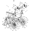
- FIG. 1 is a perspective view showing a wheelchair as a moving body to which a detachable propulsion system for a moving body according to an embodiment of the present invention is to be mounted.
- FIG. 2A is a perspective view showing an electric wheelchair equipped with a detachable propulsion system for a moving body.
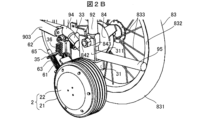
- FIG. 2B is an enlarged view of a portion of FIG. 2A.
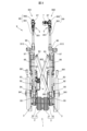
- FIG. 3 is an explanatory diagram showing the electric wheelchair in a folded state as seen from the rear.
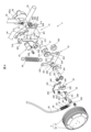
- FIG. 4 is an exploded perspective view of the support mechanism and its surroundings.
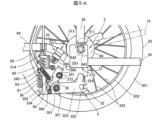
- FIG. 5A is a configuration diagram showing the support mechanism and its surroundings as viewed from the inside of the rear wheel.
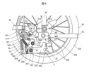
- FIG. 5B is a configuration diagram showing the support mechanism and its surroundings as viewed from the opposite side to FIG.
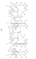
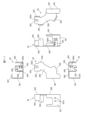
- FIG. 6 is a four-sided view showing the bracket.
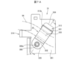
- FIG. 7A is a configuration diagram showing the rotation restricting portion of the bracket and the anti-rotation member as viewed from the inside in the vehicle width direction.
- 7B is a cross-sectional view showing a cross section of the bracket taken along line AA in FIG. 7A together with the anti-rotation member.
- FIG. 8 is a diagram showing a modified example in which the bracket is fixed to the vehicle body by a bolt.
- FIG. 9A is a perspective view showing the grip and brake lever of a wheelchair before the propulsion system is attached.
- FIG. 9B is a perspective view showing the braking operation state detection device and its surroundings.
- FIG. 10 is an exploded perspective view of the brake mechanism and the braking operation state detection device.
- FIG. 11 is a six-view diagram of the sensor bracket.
- FIG. 12 is a front view showing the sensor.
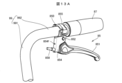
- FIG. 13A is a perspective view showing the grip and brake lever of a wheelchair before a braking operation state detection device according to a modified example is attached.
- FIG. 13B is a perspective view showing a braking operation state detection device according to a modified example attached to a wheelchair and its surroundings.
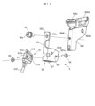
- FIG. 14 is an exploded perspective view of a braking operation state detection device and a brake mechanism according to a modified example.
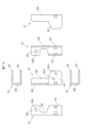
- FIG. 15 is a six-view diagram of a sensor bracket according to a modified example.
- FIG. 1 is a perspective view showing a wheelchair 8 as a mobile body on which a detachable propulsion system for a mobile body 1 according to an embodiment of the present invention is mounted.
- FIG. 2A is a perspective view showing an electric wheelchair 80 in which a detachable propulsion system for a mobile body 1 is mounted on the wheelchair 8.
- FIG. 2B is an enlarged view showing a part of FIG. 2A.
- FIG. 3 is an explanatory diagram showing the electric wheelchair 80 in a folded state as seen from behind.
- a detachable propulsion system for a moving body 1 is described as being applied to a manually operated wheelchair 8.
- the detachable propulsion system for a moving body of the present invention can be applied to various moving bodies, not limited to wheelchairs, and is particularly suitable for use with manually operated vehicles (manual vehicles) that have wheels and a body and can be moved by being pushed by a person, such as a handcart or a pushcart.
- propulsion system 1 refers to a person who sits in electric wheelchair 80
- user refers to a person who uses electric wheelchair 80 to transport the passenger to their destination.
- User, etc.” refers to general users including the user, and includes a person who performs installation and removal of detachable propulsion system for mobile body 1 together with or on behalf of the user, but does not include a person who performs installation and removal of detachable propulsion system for mobile body 1 as a business (for example, an employee of the manufacturer of detachable propulsion system for mobile body 1).
- detachable propulsion system for mobile body 1 will be simply referred to as propulsion system 1.
- forward refers to the forward direction of the electric wheelchair 80
- rearward refers to the opposite direction
- Left and right refer to the left and right in relation to the forward direction of the electric wheelchair 80
- upper and lower refer to the top and bottom in the vertical direction.
- Downward refers to the side where the front wheels 82 and rear wheels 83 touch the ground
- upper refers to the opposite side.
- the wheelchair 8 has a seat 811 for carrying a passenger, a backrest 812, armrests 813, a flip-up footrest plate 814, front and rear wheels 82 and 83, a hub unit 84 that rotatably supports the rear wheels 83, a brake mechanism 85 that brakes the wheelchair 8, a rear wheel lock mechanism 86 that stops the rotation of the rear wheels 83, a grip 87 that the user holds, and a body 9 having multiple frames that form the skeleton of the wheelchair 8.
- the armrests 813, the footrest plate 814, the front and rear wheels 82 and 83, the hub unit 84, the brake mechanism 85, the rear wheel lock mechanism 86, and the grip 87 are provided in pairs on the left and right.
- the body 9 has a left body section 901 and a right body section 902 of a frame structure, and multiple cross bars 903 arranged in an X-shape between the left body section 901 and the right body section 902.
- the wheelchair 8 can be folded as shown in FIG. 3 by bringing the left body section 901 and the right body section 902 closer together. Since the wheelchair 8 is foldable, for example, after the passenger in the wheelchair 8 is loaded into a car, the wheelchair 8 can be folded and loaded into the car, which increases convenience.
- the footrest plate 814 is flipped up, and the seat section 811 and the backrest section 812 are folded in half. Note that the seat section 811 and the backrest section 812 are not shown in FIG. 3.
- the left and right vehicle sections 901 and 902 each have a front leg frame 91, a rear leg frame 92, a seat frame 93 that connects the front leg frame 91 and the rear leg frame 92 directly below the seat 811, a connecting frame 94 that connects the front leg frame 91 and the rear leg frame 92 below the seat frame 93, a tipping frame 95 that extends rearward from the lower end of the rear leg frame 92, a foot plate frame 96 that supports the foot plate 814, an armrest frame 97 to which the armrest 813 is attached, a backrest frame 98 that supports the backrest 812 behind the armrest frame 97, a handle frame 99 that can be tilted backward relative to the backrest frame 98, and a locking section 90 that locks the handle frame 99 to the backrest frame 98.
- the front wheels 82 are attached to the lower end of the front leg frame 91.
- the hub unit 84 is attached to the lower end of the rear leg frame 92.
- the tipping frame 95 is stepped on by the user when the wheelchair 8 goes over a step, for example, and lifts the front wheels 82 upward with the rear wheels 83 as a fulcrum.
- the handle frame 99 integrally comprises a backrest support part 991 that supports the upper part of the backrest part 812, and a handle part 992 to which a grip 87 is attached, and is bent so that the handle part 992 extends rearward from the upper end of the backrest support part 991.
- the handle frame 99 can be tilted relative to the backrest frame 98, allowing the wheelchair 8 to be folded more compactly.
- the brake mechanism 85 has a brake lever 851 located near the grip 87, and when the user grips the brake lever 851 so that it approaches the grip 87, a mechanical friction brake built into the hub unit 84 is activated via a wire (not shown), generating a braking force that slows down or stops the wheelchair 8.
- This mechanical friction brake is, for example, a drum brake that generates friction by pressing a brake shoe against the inner surface of a brake drum that rotates together with the hub wheel 841.
- the rear wheel lock mechanism 86 has a lock lever 861 operated by the user or rider, and a pressure bar 862 that operates to bite into the tire 831 of the rear wheel 83 when the lock lever 861 is operated.
- the rear wheel 83 has a tire 831, a rim 832 to which the tire 831 is attached, and a number of spokes 833 that connect the hub wheel 841 of the hub unit 84 to the rim 832.
- the hub unit 84 has a hub shaft 842 that rotatably supports the hub wheel 841 relative to the vehicle body 9, and the hub shaft 842 is inserted into the rear leg frame 92.
- the hub shaft 842 is fixed to the vehicle body 9 by screwing a hub nut 843 into the tip portion that protrudes inward in the vehicle width direction from the rear leg frame 92.
- the hub shaft 842 is an axial body into which the hub nut 843 is screwed.
- the propulsion system 1 assists the user to move the wheelchair 8 with light force, and the user can attach and detach the propulsion system 1 to the wheelchair 8.
- the propulsion system 1 has a propulsion device 2 that generates a propulsive force to propel the wheelchair 8, a support mechanism 3 that supports the propulsion device 2 on the frame of the body 9 of the wheelchair 8, a control device 4 that controls the propulsion device 2, a brake operation state detection device 5 that sends a signal to the control device 4 indicating the operation state of the brake mechanism 85 by the user, a switch panel 7 that allows the user to turn the power of the control device 4 on and off, and a lock mechanism 6 that locks the propulsion device 2 in response to the operation of the lock lever 861.
- the propulsion device 2, support mechanism 3, brake operation state detection device 5, and lock mechanism 6 are a left-right pair and are attached to the left body part 901 and the right body part 902, respectively.
- the propulsion system 1 is an add-on type that can be retrofitted to a commercially available wheelchair 8, and by attaching the propulsion system 1 to the wheelchair 8, the wheelchair 8 becomes an electric wheelchair 80. Because the user can attach and detach the propulsion system 1 to the wheelchair 8, for example, if a malfunction occurs in any of the devices that make up the propulsion system 1, the user can remove the propulsion system 1 from the wheelchair 8 and use it as a manual wheelchair 8. It is also possible for the user to replace the removed propulsion system 1 with a different propulsion system 1.
- the propulsion system 1 is characterized in that the support mechanism 3 and the braking operation state detection device 5 are configured to be easily attached and detached to the body 9 of the wheelchair 8. Because the support mechanism 3 and the braking operation state detection device 5 function by connecting with the moving parts of the wheelchair 8, depending on the configuration, special devices or tools may be required to attach and detach them to the wheelchair 8, making it difficult for the user to attach and detach them. However, in this embodiment, the user can attach and detach the propulsion system 1 to the wheelchair 8 using general-purpose tools such as a spanner, wrench, or screwdriver.
- the propulsion device 2 is an in-wheel motor, and includes a wheel 21 that comes into contact with the ground or road surface, and a case 22.
- a rotor that rotates integrally with the wheel 21 and a stator that cannot rotate relative to the case 22 are housed within the case 22, and the wheel 21 rotates relative to the case 22 due to torque generated by a current supplied from the control device 4. This torque becomes the propulsive force that propels the wheelchair 8.
- the control device 4 detects the force with which the user pushes the wheelchair 8, and supplies the propulsion device 2 with a current of a magnitude that corresponds to the force with which the user pushes the wheelchair 8.
- the control device 4 detects the force with which the user pushes the wheelchair 8 based on the relationship between the current supplied to the propulsion device 2 and the rotation speed. This eliminates the need to attach a sensor such as a pressure sensor to the wheelchair 8 to detect the force with which the user pushes the wheelchair 8.
- a sensor such as a pressure sensor
- the grip 87 may be made slidable in the forward and backward directions relative to the handle portion 992, and the control device 4 may detect the force with which the user pushes the wheelchair 8 by this sliding motion.
- the control device 4 is supplied with direct current from a battery (not shown).
- the control device 4 switches this direct current using PWM control and supplies it to the propulsion device 2.
- the battery may be built into the control device 4, for example, or may be detachable from the control device 4. The remaining battery charge is displayed on the switch panel 7.
- Figure 4 is an exploded perspective view of the support mechanism 3 and its surroundings.
- Figure 5A is a structural diagram showing the support mechanism 3 and its surroundings as viewed from the inside of the rear wheel 83.
- Figure 5B is a structural diagram showing the support mechanism 3 and its surroundings as viewed from the opposite side to Figure 5A, with the rear wheel 83 omitted. Note that although Figures 4, 5A, and 5B show the support mechanism 3 attached to the right vehicle body section 902, the support mechanism 3 attached to the left vehicle body section 901 is configured in the same way.
- FIGS. 4 and 5A show the wire 61, tube 62, spring 63, wire end member 64 fixed to one end of wire 61, and tube end member 65 fixed to one end of tube 62, which constitute the locking mechanism 6.
- a portion of the wire 61 in the longitudinal direction is exposed from tube end member 65, and a spring 63 is disposed around the exposed wire 61.
- the locking mechanism 6 also has a support plate 60 (see FIG. 2A) attached to the connecting frame 94, and the other end of the tube 62 is fixed to the support plate 60.
- the other end of the wire 61 extends downward from the tube 62 fixed to the support plate 60 and is connected to the rear wheel locking mechanism 86.
- the main components of the support mechanism 3 are a bracket 31 fixed to the vehicle body 9, a support member 32 attached to the bracket 31 so as to be able to swing, a rotation prevention member 33 that prevents the bracket 31 from rotating relative to the vehicle body 9, a side plate 34 fixed to the support member 32, a stopper 35 that is connected to the side plate 34 so as to be able to swing and that operates in conjunction with the lock lever 861, a coil spring 36 that serves as a biasing member that is stretched between the bracket 31 and the side plate 34, and a cylindrical spacer 37 that is disposed between the bracket 31 and the support member 32.
- Figure 6 is a four-sided view of the bracket 31.
- the bracket 31 is for removably attaching the propulsion device 2 to the wheelchair 8, and is made of a single pressed steel plate.
- the bracket 31 is integrally made of a fixed part 311 that is fastened to the vehicle body 9 by a hub nut 843 as a fixing device, a propulsion device connecting part 312 for connecting the propulsion device 2, a rotation restricting part 313 that restricts the rotation of the bracket 31 relative to the vehicle body 9 around the fixed part 311, a spring mounting part 314 to which one end of the coil spring 36 is attached, and a pair of restricting parts 315, 316 that restrict the swing angle of the support member 32 relative to the propulsion device connecting part 312.
- the bracket 31 also has a first plate portion 301 provided with a propulsion device connection portion 312 and a rotation restriction portion 313, a second plate portion 302 and a third plate portion 303 extending from the front end of the first plate portion 301 toward the inside in the vehicle width direction of the wheelchair 8, a fourth plate portion 304 extending from the rear end of the first plate portion 301 toward the inside in the vehicle width direction of the wheelchair 8, and a fifth plate portion 305 extending upward from the fourth plate portion 304.
- the fixing portion 311 is provided on the fifth plate portion 305.
- the spring mounting portion 314 is provided on the second plate portion 302.
- one limiting part 315 restricts the swinging of the support member 32 in the direction in which the propulsion device 2 moves vertically upward
- the other limiting part 316 restricts the swinging of the support member 32 in the direction in which the propulsion device 2 moves vertically downward.
- the limiting parts 315, 316 restrict the amount of vertical movement of the propulsion device 2 relative to the rear leg frame 92 and the connecting frame 94 of the vehicle body 9.
- One limiting part 315 is provided on the fourth plate part 304
- the other limiting part 316 is provided on the third plate part 303.
- the connection part 900 between the rear leg frame 92 and the connecting frame 94 abuts against the upper surface 304a of the fourth plate part 304, and the weight of the wheelchair 8 and the passenger is supported by the fourth plate part 304.
- the support member 32 supports the propulsion device 2 and connects the propulsion device connecting portion 312 of the bracket 31 to the propulsion device 2.
- the coil spring 36 biases the support member 32 in a direction in which the wheels 21 of the propulsion device 2 touch the ground.
- the support member 32 is attached to the propulsion device connecting portion 312 of the bracket 31 so as to be able to swing with respect to the propulsion device connecting portion 312 of the bracket 31 by a bolt 381 inserted through a spacer 37.
- Low-friction washers 371, 372 are disposed between the spacer 37 and the support member 32, and between the support member 32 and the bolt 381.
- the low-friction washers 371, 372 are low-friction members that have been treated on the front and back surfaces with a surface treatment such as fluororesin to reduce the coefficient of friction, and the low-friction washers 371, 372 allow the support member 32 to swing smoothly relative to the bracket 31.
- the bolt 381 is inserted into a bolt insertion hole 312a formed in the propulsion device connection part 312 of the bracket 31, and a nut 382 is screwed onto the tip of the bolt.
- the support member 32 is integrally formed with an attachment portion 321 having a bolt insertion hole 321a through which the bolt 381 is inserted, a fixing portion 322 to which the attachment bolt 221 (see FIG. 5B) protruding from the case 22 of the propulsion device 2 is fixed by a nut 383, an arm portion 323 extending in the front-rear direction between the attachment portion 321 and the fixing portion 322, a contact portion 324 that contacts one of the limiting portions 315 of the bracket 31 when the propulsion device 2 moves vertically upward, and a pair of side plate fixing portions 325, 326 for fixing the side plate 34.
- the abutment portion 324 protrudes upward from the end of the arm portion 323 on the fixed portion 322 side.
- the lower side plate fixing portion 326 abuts against the other limiting portion 316 of the bracket 31 when the support member 32 swings so that the propulsion device 2 moves vertically downward.
- the side plate 34 integrally includes fixed portions 341, 342 fixed to the side plate fixing portions 325, 326 of the support member 32, a tube fixing portion 343 to which the tube end member 65 is fixed, a spring mounting portion 344 to which the other end of the coil spring 36 is attached, and a stopper connecting portion 345 to which the stopper 35 is swingably connected.
- the side plate 34 swings integrally with the support member 32 relative to the bracket 31 as the fixed portions 341, 342 are fixed to the side plate fixing portions 325, 326 of the support member 32 by bolts 384, 385, respectively.
- the spring mounting portion 344 of the side plate 34 is provided in front of the spacer 37 and the bolt 381, and the spring mounting portion 344 is urged upward by the restoring force of the coil spring 36, which urges the fixing portion 322 of the support member 32 downward with the bolt 381 as the pivot. As a result, the propulsion device 2 is pressed downward so that the wheels 21 touch the ground.
- the stopper 35 is swingably connected to the stopper connecting portion 345 by a bolt 386 and a nut 387.
- the stopper 35 integrally has a supported portion 351 supported by the bolt 386, an engagement portion 352 with which the wire end member 64 engages, and a pressing portion 353 arranged on the outer periphery of the wheel 21.
- the stopper 35 swings relative to the side plate 34 around the bolt 386 as the engagement portion 352 is pulled toward the tube fixing portion 343 of the side plate 34 in response to the operation of the lock lever 861.
- the pressing portion 353 faces the wheel 21 of the propulsion unit 2, and when the lock lever 861 is operated in a direction to lock the rear wheel 83, the pressing portion 353 comes into contact with the wheel 21 to lock the wheel 21.
- FIG. 7A is a diagram showing the rotation restriction portion 313 of the bracket 31 and the anti-rotation member 33 as viewed from the inside in the vehicle width direction.
- FIG. 7B is a cross-sectional view showing the cross section of the bracket 31 along line A-A in FIG. 7A together with the anti-rotation member 33.
- the connecting frame 94 is indicated by a two-dot chain line.
- the anti-rotation member 33 grips a part of the connecting frame 94 together with the bracket 31.
- the rotation restriction portion 313 restricts the rotation of the bracket 31 relative to the vehicle body 9 by attaching the anti-rotation member 33.
- the frame of the vehicle body 9 gripped by the anti-rotation member 33 is not limited to the connecting frame 94, and may be, for example, the rear leg frame 92 or the tipping frame 95.
- the anti-rotation member 33 restricts the rotation of the bracket 31 relative to the rear leg frame 92 of the vehicle body 9 around the hub shaft 842 and the hub nut 843 so that the fastening state of the fixing part 311 by the hub nut 843 does not loosen.
- the anti-rotation member 33 is curved in a U-shape so as to surround a part of the connecting frame 94 together with the bracket 31, and integrally includes an upper plate part 331 arranged on the upper side of the connecting frame 94, a lower plate part 332 arranged on the lower side of the connecting frame 94, a connection part 333 between the upper plate part 331 and the lower plate part 332, a locking piece 334 that locks with the rotation restricting part 313 of the bracket 31, and a fixed piece 335 that is fixed to the rotation restricting part 313 of the bracket 31.
- a linear slit 313a is formed in the rotation restriction portion 313 of the bracket 31, and the locking piece 334 is inserted into the slit 313a from the inside to the outside in the vehicle width direction.
- the fixed piece 335 is fixed to the bracket 31 by a bolt 388 that screws into a nut 389 fixed to the bracket 31 by welding, for example.
- a bolt insertion hole 335a is formed in the fixed piece 335, through which the bolt 388 is inserted.
- a bolt insertion hole 313b is formed in the rotation restriction portion 313, through which the bolt 388 is inserted.
- the anti-rotation member 33 prevents the bracket 31 from rotating relative to the vehicle body 9 by sandwiching the connecting frame 94 between the upper plate portion 331 and the lower plate portion 332. This makes it possible to prevent the bracket 31 from rotating without drilling holes or performing other processing on the vehicle body 9.
- the bolt 388 that fixes the anti-rotation member 33 to the bracket 31 is a hexagonal socket bolt with a hexagonal tool fitting hole 388a formed therein, and the user can attach and detach the anti-rotation member 33 to the bracket 31 by rotating the bolt 388 with a general-purpose hexagonal wrench.
- the hub shaft 842 is inserted into an opening 311a formed in the fixing portion 311 of the bracket 31, and a hub nut 843 serving as a fixing device is screwed into the male threaded portion 842a formed at the tip of the hub shaft 842, thereby fastening and fixing the fixing portion 311 to the vehicle body 9.
- the bracket 31 can be removed from the vehicle body 9 by releasing the fastening by the hub nut 843.
- the support mechanism 3 can be removed from the wheelchair 8 together with the propulsion device 2 without disassembling the support mechanism 3 itself.
- a general-purpose tool refers to a tool that is generally available to users.
- a spanner 10 is shown as an example of a general-purpose tool.
- the bracket 31 may be detachable from the vehicle body using, for example, a wrench or a screwdriver, rather than a spanner.
- the opening 311a in the fixing portion 311 of the bracket 31 opens upward, and when removing the bracket 31 from the vehicle body 9, the hub nut 843 can be loosened to the extent that it does not tighten the fixing portion 311 without removing the hub nut 843 from the hub shaft 842, and the bracket 31 can be removed from the vehicle body 9 by moving the bracket 31 downward relative to the vehicle body 9. Also, in this embodiment, because the opening 311a opens upward as described above, even if the hub nut 843 loosens while the electric wheelchair 80 is in use, the bracket 31 is prevented from coming off and falling off the vehicle body 9 due to the weight of the electric wheelchair 80 or the weight of the passenger.
- a circular hole may be formed in the fixing portion 311 of the bracket 31, and the hub nut 843 may be inserted into the circular hole to fasten the fixing portion 311 by the hub nut 843.
- the fixing portion 311 may be fastened to the vehicle body 9 by a bolt inserted into a bolt insertion hole formed in the vehicle body 9.
- FIG. 8 is a diagram showing a modified example in which the bracket 31 is fixed to the vehicle body 9 by a bolt 39.
- the bolt 39 is a fastener that tightens and fixes the bracket 31 to the frame of the vehicle body 9 in the modified example shown in FIG. 8, and is inserted into a bolt insertion hole formed in the connection 900 between the rear leg frame 92 and the connecting frame 94.
- the bolt 39 is fixed to the vehicle body 9, for example, by screwing into a nut arranged on the rear wheel 83 side of the rear leg frame 92 and the connecting frame 94.
- the bolt 39 is rotated with a general-purpose tool such as a hex wrench.
- Figure 9A is a perspective view showing the grip 87 and the brake lever 851 of the wheelchair 8 before the braking operation state detection device 5 is attached.
- Figure 9B is a perspective view showing the braking operation state detection device 5 and its surroundings after attachment.
- Figure 10 is an exploded perspective view of the braking operation state detection device 5 and part of the brake mechanism 85.
- the brake mechanism 85 of the wheelchair 8 includes a brake lever 851 that is manually operated by the user, a pin 852 that is inserted into a through hole 851a formed in the end of the brake lever 851, a retaining member 853 that prevents the pin 852 from falling out, a holder 854 that supports the pin 852 and holds the brake lever 851, a hook 855 that holds the handle portion 992 of the handle frame 99 between the holder 854 and the holder, a bolt 856 as a fastening member that secures the holder 854 and the hook 855 to each other, a brake wire 857 having one longitudinal end fixed to the brake lever 851, and a tube 858 having one longitudinal end fixed to the holder 854.
- the brake lever 851 When the user grips the brake lever 851 together with the grip 87, the brake lever 851 rotates around the pin 852, pulling the brake wire 857 and activating the mechanical friction brake built into the hub unit 84.
- the brake wire 857 is inserted through the tube 858.
- the holder 854 and hook 855 are made of a hard resin such as engineering plastic, and a screw hole 854a is formed in the holder 854.
- the holder 854 is fastened to the handle portion 992 of the handle frame 99 by being fixed to the hook 855 by a bolt 856.
- the holder 854 and hook 855 sandwich the handle portion 992 on either side. Note that the holder 854 and hook 855 are not limited to being made of resin, and may be made of other materials.
- the holder 854 has a through hole 854b formed therein for inserting the pin 852.
- the holder 854 and the hook 855 are mounting members for mounting the brake lever 851 to the handle portion 992 of the handle frame 99.
- the bolt 856 has a hexagonal tool fitting hole 856a, allowing the user to tighten and loosen the bolt with a general-purpose hexagonal wrench.
- the brake operation state detection device 5 includes a sensor 51 that detects the operation state of the brake mechanism 85 by the user, a sensor bracket 52 that fixes the sensor 51 to the wheelchair 8, a guide member 53 that guides a cable 510 extending from the sensor 51 to the backrest support part 991 side of the handle frame 99, and a bolt 54 and a nut 55 for fixing the sensor 51 to the sensor bracket 52.
- the sensor 51 transmits a signal indicating the operation state of the brake mechanism 85 to the control device 4 via the cable 510.
- the control device 4 When the control device 4 receives a signal from the brake operation state detection device 5 indicating that the user has operated the brake mechanism 85 to generate a braking force, the control device 4 performs a propulsion force reduction control to reduce the propulsion force generated by the propulsion device 2.
- a propulsion force reduction control is to set the control device 4 to a state in which no current is supplied to the propulsion device 2.
- the propulsion force generated by the propulsion device 2 is reduced, so that the electric wheelchair 80 can be stopped or slowed down smoothly.
- the user of the electric wheelchair 80 may operate the brake lever 851 while pressing the grip 87 as if putting his/her weight forward.
- the propulsion force generated by the propulsion device 2 is reduced even in such a case, so that the braking force of the mechanical friction brake by the brake mechanism 85 and the propulsion force of the propulsion device 2 are prevented from canceling each other out, and the electric wheelchair 80 can be stopped or slowed down smoothly.
- the sensor bracket 52 is a component for removably mounting the sensor 51 to the wheelchair 8.
- the sensor bracket 52 is made of a single pressed steel plate.
- the sensor bracket 52 is integrally provided with a sensor mounting portion 521 for mounting the sensor 51, a fixing portion 522 for fixing the sensor to the handle portion 992 of the handle frame 99, a pair of anti-rotation portions 523, 524 for preventing the sensor bracket 52 from rotating relative to the holder 854, a mounting portion 525 for mounting the guide member 53, a connection portion 526 extending downward from the fixing portion 522 and connecting the fixing portion 522 and the sensor mounting portion 521, and a cover portion 527 for protecting the sensor 51 mounted on the sensor mounting portion 521 from external impact.
- the sensor bracket 52 is prevented from rotating relative to the holder 854 by one of the pair of anti-rotation portions 523, 524, the anti-rotation portion 523 abutting against the rear side of the holder 854, and the other anti-rotation portion 524 abutting against the front side of the holder 854.
- the 12 is a front view of the sensor 51.
- the sensor 51 has a cable 510, a case 511, a lever 512 attached to the case 511, and a switch 513 with a portion protruding from the case 511.
- the sensor 51 is disposed below the brake lever 851 so that the lever 512 is disposed between the brake lever 851 and the switch 513.
- the switch 513 is a push button switch having a button 513a that is pressed by the lever 512, and transmits a binary signal of on or off to the control device 4. For example, this binary signal is turned on when the user grips the brake lever 851, and turned off when the user releases the brake lever 851. In this way, the sensor 51 detects the movement of the brake lever 851 relative to the holder 854 as the operating state of the brake mechanism 85, and transmits information on the detection result to the control device 4.
- the sensor 51 is removably attached to the sensor bracket 52 by a bolt 54 and a nut 55.
- the bolt 54 is inserted through a bolt insertion hole 521a formed in the sensor mounting portion 521 of the sensor bracket 52 and a bolt insertion hole 511a formed in the case 511 of the sensor 51, and is screwed into the nut 55.
- the bolt 54 is a hexagonal socket bolt, and the user can attach and detach the sensor 51 to the sensor bracket 52 with a general-purpose tool such as a hexagonal wrench.
- the case 511 of the sensor 51 is provided with a protrusion 511b for preventing rotation, and this protrusion 511b fits into a fitting hole 521b formed in the sensor mounting portion 521 of the sensor bracket 52 to prevent the case 511 from rotating.
- the guide member 53 that guides the cable 510 is a resin band.
- the mounting portion 525 of the sensor bracket 52 is formed with a pair of through holes 525a through which the guide member 53 passes.
- the fixing part 522 of the sensor bracket 52 has a bolt insertion hole 522a formed therein for inserting the bolt 856.
- the bolt 856 fixing the holder 854 and the hook 855 is temporarily removed, and the removed bolt 856 is inserted into the bolt insertion hole 522a of the fixing part 522, and then the holder 854 and the hook 855 are fixed again by the bolt 856.
- the fixing part 522 of the sensor bracket 52 is fixed to the handle frame 99 via the holder 854 by the bolt 856.
- the bolt 856 is loosened and removed using a general-purpose tool, and the bolt 856 is removed from the bolt insertion hole 522a of the fixing part 522.
- the holder 854 and the hook 855 are then fixed again by the bolt 856.
- the fixing part 522 of the sensor bracket 52 can be attached and detached to the handle frame 99 of the vehicle body 9 using the general-purpose tool.
- the sensor 51 can be attached to and detached from the sensor bracket 52 using a general-purpose tool as described above, when removing the propulsion system 1 from the wheelchair 8, the sensor 51 can be removed from the sensor bracket 52 while leaving the sensor bracket 52 attached to the wheelchair 8.
- the user or the like can easily attach and detach the propulsion device 2 that propels the wheelchair 8 with a general-purpose tool.
- the user or the like can also easily attach and detach the braking operation state detection device 5 with a general-purpose tool, so that when a failure occurs in any of the components of the propulsion system 1, the user or the like can remove the propulsion system 1 from the wheelchair 8 and use it as a manual wheelchair 8.
- Fig. 13A is a perspective view showing the grip 87 and the brake lever 851 of the wheelchair 8 before the braking operation state detection device 5 is attached.
- Fig. 13B is a perspective view showing the braking operation state detection device 5 and its surroundings after attachment.
- Fig. 14 is an exploded perspective view of the braking operation state detection device 5 and a part of the brake mechanism 85.
- Fig. 15 is a six-sided view of a sensor bracket 52 relating to a modified example.
- the holder 854 and hook 855 are fixed by bolt 856, and the holder 854 and hook 855 sandwich the handle portion 992 of the handle frame 99 from the left and right.
- the holder 854 and hook 855 are fixed by bolt 850, and the handle portion 992 of the handle frame 99 is sandwiched from above and below.
- the hook 855 extends in the left-right direction, with one end engaged with the holder 854 and the other end fixed to the holder 854 by the bolt 850.
- the holder 854 is made of a single pressed steel plate. As shown in FIG. 14, the holder 854 is formed with a through hole 854c for inserting the pin 852, a locking portion 854d for locking one end of the hook 855, a screw hole 854e into which the bolt 850 screws, and a mounting hole 854f for attaching the sensor bracket 52.
- the sensor bracket 52 is made of a single pressed steel plate and integrally comprises a sensor mounting portion 521 for mounting the sensor 51, a fixing portion 522 for fixing to the handle portion 992 of the handle frame 99, a connection portion 526 that extends downward from the fixing portion 522 and connects the fixing portion 522 and the sensor mounting portion 521, and a cover portion 527 that protects the sensor 51 attached to the sensor mounting portion 521 from external impacts.
- the sensor mounting portion 521 of the sensor bracket 52 has a bolt insertion hole 521a and a fitting hole 521b formed therein, and the sensor 51 is attached to the sensor mounting portion 521 by a bolt 54 and a nut 55.
- the mounting hole 854f of the holder 854 is a screw hole
- the sensor bracket 52 is fixed to the holder 854 by a bolt 56 that screws into the mounting hole 854f.
- the bolt 56 is a hexagonal socket bolt with a hexagonal tool fitting hole 56a formed therein, and the user can tighten the bolt 56 into the mounting hole 854f with a hexagonal wrench, which is a general-purpose tool.
- the fixing portion 522 of the sensor bracket 52 is formed with a bolt insertion hole 522a for inserting the bolt 56.
- the bolt 56 When fixing the sensor bracket 52 to the holder 854, the bolt 56 is inserted into the bolt insertion hole 522a formed in the fixing portion 522 of the sensor bracket 52, and the bolt 56 is fastened to the mounting hole 854f using a general-purpose tool.
- the fixing portion 522 of the sensor bracket 52 is fixed to the handle frame 99 via the holder 854 by the bolt 56.
- the bolt 56 When removing the sensor bracket 52 from the holder 854, the bolt 56 is loosened using a general-purpose tool. In this manner, with this modified example as well, as with the above embodiment, the user can easily attach and detach the brake operation state detection device 5 to the wheelchair 8 using a general-purpose tool.
- the propulsion device 2 is connected to the bracket 31 via the support member 32, but the propulsion device 2 may be directly connected to the propulsion device connection part 312 of the bracket 31 without the support member 32.
- the propulsion device 2 is not limited to an in-wheel motor, and various configurations that generate propulsive force by rotating the wheels with an electric motor can be used.
- the fixing part 522 of the sensor bracket 52 is fixed to the handle frame 99 via the holder 854, but the fixing part 522 of the sensor bracket 52 may be fixed directly to the handle frame 99 with a general-purpose tool.
Landscapes
- Health & Medical Sciences (AREA)
- Life Sciences & Earth Sciences (AREA)
- Animal Behavior & Ethology (AREA)
- General Health & Medical Sciences (AREA)
- Public Health (AREA)
- Veterinary Medicine (AREA)
- Handcart (AREA)
Abstract
【課題】移動体を推進させる推進装置をその使用者等が容易に着脱することを可能とする移動体用ブラケット及び推進装置支持機構を提供する。 【解決手段】車椅子(8)を推進させる推進力を発生する推進装置(2)を車椅子(8)に着脱可能に取り付けるためのブラケット(31)は、車椅子(8)のフレームにハブナット(843)によって締付固定される固定部(311)と、推進装置(2)を連結するための推進装置連結部(312)と、を一体に有する。固定部(311)は、汎用工具によってハブナット(843)による締め付けを解除することにより、車椅子(8)のフレームから取り外し可能である。
Description
本発明は、移動体を推進させる推進力を発生する推進装置を移動体に取り付けるための移動体用ブラケット、及び推進装置を移動体のフレームに対して支持する推進装置支持機構に関する。
従来、電動モータの駆動力により走行することが可能な電動車椅子が知られている。特許文献1に記載の電動車椅子は、左右の後輪にそれぞれ対応して電動モータが取り付けられており、電動モータが制御回路により制御される。制御回路は、介護者が把持する操作部の操作力検知部により操作力を検知し、操作部に車椅子を推進させる操作力が入力されると、その操作力に基づいた駆動力をモータに出力させ、操作力が付与されなくなると、制動力を零から徐々に増大させる。
上記のように構成された電動式の車椅子において、電動モータ又は制御回路が故障すると、介護者が車椅子を押して前進又は後退させるときに電動モータが負荷となり、車椅子を動かすために電動式でない車椅子よりも大きな力が必要となる。また、電動モータ又は制御回路が故障した場合に車輪から電動モータを取り外せば、電動モータが負荷となることを避けられるが、特許文献1に記載されたもののように電動モータで車輪を駆動することを前提として組み立てられた電動車椅子は、介護者等の一般ユーザが電動モータを取り外せるようには構成されていない。
そこで、本発明は、移動体を推進させる推進装置をその使用者等が容易に着脱することを可能とする移動体用ブラケット及び推進装置支持機構を提供することを目的とする。
本発明は、上記の目的を達成するため、移動体を推進させる推進力を発生する推進装置を前記移動体に着脱可能に取り付けるための移動体用ブラケットであって、前記移動体のフレームに固定具によって締付固定される固定部と、前記推進装置を連結するための推進装置連結部と、を一体に有し、前記固定部は、汎用工具によって前記固定具による締め付けを解除することにより前記移動体の前記フレームから取り外し可能である、移動体用ブラケットを提供する。
また、本発明は、上記の目的を達成するため、接地する車輪の回転によって移動体を推進させる推進力を発生する推進装置を前記移動体のフレームに対して支持する推進装置支持機構であって、前記移動体の前記フレームに固定具によって締付固定される固定部と、前記推進装置を連結するための推進装置連結部と、を一体に有するブラケットを備え、前記ブラケットは、汎用工具によって前記固定具による前記固定部の締め付けを解除することにより前記移動体の前記フレームから取り外し可能である、推進装置支持機構を提供する。
本発明に係る移動体用ブラケット及び推進装置支持機構によれば、移動体を推進させる推進装置をその使用者等が容易に着脱することが可能となる。
[実施の形態]
本発明の実施の形態について、図面を参照して説明する。なお、以下に説明する実施の形態は、本発明を実施する上での好適な具体例として示すものであり、技術的に好ましい種々の技術的事項を具体的に例示している部分もあるが、本発明の技術的範囲は、この具体的態様に限定されるものではない。
本発明の実施の形態について、図面を参照して説明する。なお、以下に説明する実施の形態は、本発明を実施する上での好適な具体例として示すものであり、技術的に好ましい種々の技術的事項を具体的に例示している部分もあるが、本発明の技術的範囲は、この具体的態様に限定されるものではない。
図1は、本発明の実施の形態に係る移動体用着脱式推進システム1の搭載対象である移動体としての車椅子8を示す斜視図である。図2Aは、車椅子8に移動体用着脱式推進システム1が搭載された電動車椅子80を示す斜視図である。図2Bは、図2Aの一部を拡大して示す拡大図である。図3は、後ろ側から見た電動車椅子80を折り畳んだ状態を示す説明図である。
本実施の形態では、移動体用着脱式推進システム1を手動式の車椅子8に適用した場合について説明する。ただし、本発明の移動体用着脱式推進システムは、車椅子に限らず様々な移動体に適用することができ、例えば台車や手押し車のように、車輪と車体を有し、人が押すことにより移動させることが可能な手動式の車両(手動車)に特に好適に適用することができる。
以下の説明において、「搭乗者」とは、電動車椅子80に着座して乗る者をいい、「使用者」とは、電動車椅子80を使用して搭乗者を目的地に運ぶ者をいう。「使用者等」とは、使用者を含む一般ユーザをいい、使用者と共に又は使用者に代わって移動体用着脱式推進システム1の装着や取り外し作業を行う者を含むが、移動体用着脱式推進システム1の装着や取り外し作業を業として行う者(例えば移動体用着脱式推進システム1のメーカーの従業員)は、「使用者等」には含まない。以下、移動体用着脱式推進システム1を単に推進システム1という。
また、以下の説明において、「前方」は、電動車椅子80の前進方向をいい、「後方」は、その反対方向をいう。「左」及び「右」は、電動車椅子80の前進方向に対する左右をいい、「上」及び「下」は、鉛直方向の上下をいう。「下方」は、前輪82及び後輪83が接地する側をいい、「上方」は、その反対側をいう。
車椅子8は、搭乗者を乗せるための座部811、背もたれ部812、肘掛け813、及び跳ね上げ式の足乗せプレート814と、前輪82及び後輪83と、後輪83を回転可能に支持するハブユニット84と、車椅子8を制動するブレーキ機構85と、後輪83の回転を停止させる後輪ロック機構86と、使用者が把持するグリップ87と、車椅子8の骨格をなす複数のフレームを有する車体9と、を有している。肘掛け813、足乗せプレート814、前輪82、後輪83、ハブユニット84、ブレーキ機構85、後輪ロック機構86、及びグリップ87は、左右一対に設けられている。
車体9は、フレーム構造の左側車体部901及び右側車体部902と、左側車体部901と右側車体部902との間でX字状にクロスして配置される複数のクロスバー903とを有している。車椅子8は、左側車体部901と右側車体部902とを接近させることにより、図3に示すように折り畳みが可能である。車椅子8が折り畳み可能であることにより、例えば車椅子8の搭乗者を自動車に乗せた後に、その自動車に車椅子8を折り畳んで乗せることができ、利便性が高まる。車椅子8を折り畳む際には、足乗せプレート814を跳ね上げ、座部811及び背もたれ部812を二つ折り状態とする。なお、図3では、座部811及び背もたれ部812の図示を省略している。
左側車体部901及び右側車体部902は、それぞれ、前脚フレーム91と、後脚フレーム92と、座部811の直下で前脚フレーム91と後脚フレーム92とを連結する座部フレーム93と、座部フレーム93の下方で前脚フレーム91と後脚フレーム92とを連結する連結フレーム94と、後脚フレーム92の下端部から後方に延びるティッピングフレーム95と、足乗せプレート814を支持する足乗せプレート用フレーム96と、肘掛け813が取り付けられた肘掛けフレーム97と、肘掛けフレーム97の後方で背もたれ部812を支持する背もたれフレーム98と、背もたれフレーム98に対して後ろ側に倒すように傾動させることが可能なハンドルフレーム99と、ハンドルフレーム99を背もたれフレーム98に対してロックするロック部90と、を有している。
前脚フレーム91の下端部には、前輪82が取り付けられている。後脚フレーム92の下端部には、ハブユニット84が取り付けられている。ティッピングフレーム95は、例えば車椅子8が段差を乗り越える際に使用者が足で踏みつけ、後輪83を支点として前輪82を上方に持ち上げるものである。ハンドルフレーム99は、背もたれ部812の上部を支持する背もたれ支持部991と、グリップ87が取り付けられたハンドル部992と、を一体に有しており、背もたれ支持部991の上端部から後方にハンドル部992が延びるように屈曲されている。ハンドルフレーム99が背もたれフレーム98に対して傾動可能であることによって、車椅子8をよりコンパクトに折り畳むことができる。
ブレーキ機構85は、グリップ87の近傍に配置されたブレーキレバー851を有し、使用者がブレーキレバー851をグリップ87に近づけるように握ることで不図示のワイヤを介してハブユニット84に内蔵された機械式の摩擦ブレーキが作動し、車椅子8を減速又は停止させる制動力を発生する。この機械式の摩擦ブレーキは、例えばハブホイール841と共に回転するブレーキドラムの内面にブレーキシューを押し付けて摩擦力を発生させるドラムブレーキである。
後輪ロック機構86は、使用者又は搭乗者が操作するロックレバー861と、ロックレバー861が操作されることにより後輪83のタイヤ831に食い込むように動作する押圧バー862と、を有している。後輪83は、タイヤ831と、タイヤ831が装着されたリム832と、ハブユニット84のハブホイール841とリム832とを繋ぐ複数のスポーク833と、を有している。
ハブユニット84は、ハブホイール841を車体9に対して回転可能に支持するハブシャフト842を有し、ハブシャフト842が後脚フレーム92に挿通されている。ハブシャフト842は、後脚フレーム92から車幅方向の内側に突出した先端部にハブナット843が螺合することにより、車体9に固定されている。ハブシャフト842は、ハブナット843が螺合する軸状体である。
推進システム1は、使用者が車椅子8を軽い力で移動させることができるようにアシストするものであり、使用者等が推進システム1を車椅子8に着脱することが可能である。推進システム1は、車椅子8を推進させる推進力を発生する推進装置2と、推進装置2を車椅子8の車体9のフレームに支持する支持機構3と、推進装置2を制御する制御装置4と、使用者によるブレーキ機構85の操作状態を示す信号を制御装置4に送る制動操作状態検出装置5と、使用者が制御装置4の電源オンオフを行うスイッチパネル7と、ロックレバー861の操作に応じて推進装置2をロックするロック機構6と、を有している。推進装置2、支持機構3、制動操作状態検出装置5、及びロック機構6は、左右一対であり、左側車体部901及び右側車体部902にそれぞれ取り付けられる。
推進システム1は、市販の車椅子8に後付け可能な後付けタイプのものであり、車椅子8に推進システム1を取り付けることにより、車椅子8が電動車椅子80となる。使用者等が推進システム1を車椅子8に着脱可能であることにより、例えば推進システム1を構成する何れかの装置に故障が発生した際には、使用者にて車椅子8から推進システム1を取り外し、手動式の車椅子8として用いることが可能である。また、使用者にて取り外した推進システム1を別の推進システム1と交換することも可能である。
本実施の形態に係る推進システム1は、特に、支持機構3及び制動操作状態検出装置5を車椅子8の車体9に対して容易に着脱可能とした構成に特徴がある。支持機構3及び制動操作状態検出装置5は、車椅子8の可動部と結合して機能を発揮するものであるため、その構成によっては車椅子8への着脱に特殊な装置や工具を要し、使用者等による着脱作業が困難となり得るが、本実施の形態では、使用者等がスパナやレンチあるいはドライバー等の汎用工具を用いて推進システム1を車椅子8に着脱可能である。
以下、推進システム1の各部の構成、及び推進システム1を車椅子8に着脱する際の手順について、詳細に説明する。
推進装置2は、インホイールモータであり、地面や路面に接地する車輪21と、ケース22と、を備えている。ケース22内には、車輪21と一体に回転するロータ、及びケース22に対して相対回転不能なステータが収容されており、制御装置4から供給される電流により発生するトルクによって車輪21がケース22に対して回転する。このトルクは、車椅子8を推進させる推進力となる。制御装置4は、使用者が車椅子8を押す力を検知して、使用者が車椅子8を押す力に応じた大きさの電流を推進装置2に供給する。
制御装置4は、推進装置2に供給する電流と回転速度との関係に基づいて使用者が車椅子8を押す力を検知する。これにより、使用者が車椅子8を押す力を検出するための圧力センサ等のセンサを車椅子8に取り付けることが不要となる。なお、例えばグリップ87をハンドル部992に対して前後方向に摺動可能とし、制御装置4がこの摺動運動により使用者が車椅子8を押す力を検知できるようにしてもよい。
制御装置4には、不図示のバッテリーから直流電流が供給される。制御装置4は、この直流電流をPWM制御によりスイッチングして推進装置2に供給する。バッテリーは、例えば制御装置4に内蔵してもよく、制御装置4に着脱可能としてもよい。バッテリーの残量は、スイッチパネル7に表示される。
図4は、支持機構3及びその周辺部の分解斜視図である。図5Aは、支持機構3及びその周辺部を後輪83の内側から見た状態を示す構成図である。図5Bは、後輪83の図示を省略して図5Aとは反対側から支持機構3及びその周辺部を見た状態を示す構成図である。なお、図4、図5A、及び図5Bでは、右側車体部902に取り付けられる支持機構3を示しているが、左側車体部901に取り付けられる支持機構3についても同様に構成されている。
図4及び図5Aでは、ロック機構6を構成するワイヤ61、チューブ62、スプリング63、ワイヤ61の一方の端部に固定されたワイヤエンド部材64、チューブ62の一方の端部に固定されたチューブエンド部材65を示している。ワイヤ61は、長手方向の一部がチューブエンド部材65から露出しており、露出したワイヤ61の外周にスプリング63が配置されている。
また、ロック機構6は、連結フレーム94に取り付けられた支持プレート60(図2A参照)を有しており、支持プレート60にチューブ62の他方の端部が固定されている。ワイヤ61の他方の端部は、支持プレート60に固定されたチューブ62から下方に延びて後輪ロック機構86に接続されている。ロックレバー861が後輪83をロックする方向に操作されると、推進装置2の近傍でチューブエンド部材65から露出したワイヤ61の一部がチューブ62内に引き込まれ、チューブエンド部材65とワイヤエンド部材64との間の距離が短くなる。
支持機構3は、車体9に固定されるブラケット31と、ブラケット31に対して揺動可能に取り付けられる支持部材32と、ブラケット31を車体9に対して回り止めする回り止め部材33と、支持部材32に固定されるサイドプレート34と、サイドプレート34に対して揺動可能に連結され、ロックレバー861に連動して動作するストッパ35と、ブラケット31とサイドプレート34との間に架け渡される付勢部材としてのコイルバネ36と、ブラケット31と支持部材32との間に配置される円筒状のスペーサ37と、を主な構成要素として有している。
図6は、ブラケット31を示す四面図である。ブラケット31は、推進装置2を車椅子8に着脱可能に取り付けるためのものであり、プレス加工された1枚の鋼板からなる。ブラケット31は、固定具としてのハブナット843によって車体9に締付固定される固定部311と、推進装置2を連結するための推進装置連結部312と、固定部311を中心としたブラケット31の車体9に対する回動を規制する回動規制部313と、コイルバネ36の一端が取り付けられるバネ取付部314と、推進装置連結部312に対する支持部材32の揺動角度を制限する一対の制限部315,316と、を一体に有している。
また、ブラケット31は、推進装置連結部312及び回動規制部313が設けられた第1板部301と、第1板部301の前方側の端部から車椅子8の車幅方向の内側に向かって延びる第2板部302及び第3板部303と、第1板部301の後方側の端部から車椅子8の車幅方向の内側に向かって延びる第4板部304と、第4板部304から上方に延びる第5板部305と、を有している。固定部311は、第5板部305に設けられている。バネ取付部314は、第2板部302に設けられている。
一対の制限部315,316のうち、一方の制限部315は、推進装置2が鉛直方向上方に移動する方向の支持部材32の揺動を規制し、他方の制限部316は、推進装置2が鉛直方向下方に移動する方向の支持部材32の揺動を規制している。これにより、車体9の後脚フレーム92及び連結フレーム94に対する推進装置2の上下方向の移動量が、制限部315,316によって規制される。一方の制限部315は、第4板部304に設けられ、他方の制限部316は、第3板部303に設けられている。第4板部304の上面304aには、後脚フレーム92と連結フレーム94との接続部900が当接し、車椅子8及び搭乗者の重量が第4板部304によって支えられる。
支持部材32は、推進装置2を支持してブラケット31の推進装置連結部312と推進装置2とを連結する。コイルバネ36は、推進装置2の車輪21を接地させる方向に支持部材32を付勢する。支持部材32は、スペーサ37に挿通されるボルト381によってブラケット31の推進装置連結部312に対して揺動可能に取り付けられている。
スペーサ37と支持部材32との間、及び支持部材32とボルト381との間には、それぞれ低摩擦ワッシャ371,372が配置されている。低摩擦ワッシャ371,372は、例えば表面及び裏面にフッ素樹脂等の摩擦係数を低下させる表面処理が施された低摩擦部材であり、低摩擦ワッシャ371,372によって支持部材32がブラケット31に対して円滑に揺動する。ボルト381は、ブラケット31の推進装置連結部312に形成されたボルト挿通孔312aに挿通され、その先端部にナット382が螺合する。
支持部材32は、ボルト381を挿通させるボルト挿通孔321aが形成された被取付部321と、推進装置2のケース22から突出した取付ボルト221(図5B参照)がナット383によって固定される固定部322と、被取付部321と固定部322との間で前後方向に延在するアーム部323と、推進装置2が鉛直方向上方に移動したときにブラケット31の一方の制限部315に当接する当接部324と、サイドプレート34を固定するための一対のサイドプレート固定部325,326と、を一体に有している。
当接部324は、アーム部323における固定部322側の端部から上方に突出している。一対のサイドプレート固定部325,326のうち、下方に位置するサイドプレート固定部326は、推進装置2が鉛直方向下方に移動するように支持部材32が揺動したときにブラケット31の他方の制限部316に当接する。
サイドプレート34は、支持部材32のサイドプレート固定部325,326に固定される被固定部341,342と、チューブエンド部材65が固定されるチューブ固定部343と、コイルバネ36の他端が取り付けられるバネ取付部344と、ストッパ35が揺動可能に連結されるストッパ連結部345と、を一体に有している。サイドプレート34は、被固定部341,342がそれぞれボルト384,385によって支持部材32のサイドプレート固定部325,326に固定されることにより、支持部材32と一体にブラケット31に対して揺動する。
サイドプレート34のバネ取付部344は、スペーサ37及びボルト381の前方に設けられており、コイルバネ36の復元力によってバネ取付部344が上方に付勢されることにより、ボルト381を支軸として支持部材32の固定部322が下方に付勢される。これにより、車輪21が接地するように、推進装置2が下方に押し付けられる。
ストッパ連結部345には、ボルト386及びナット387によってストッパ35が揺動可能に連結される。ストッパ35は、ボルト386に支持される被支持部351と、ワイヤエンド部材64が係合する係合部352と、車輪21の外周に配置される押圧部353と、を一体に有している。ストッパ35は、ロックレバー861の操作に応じて係合部352がサイドプレート34のチューブ固定部343側に引っ張られることにより、ボルト386を中心としてサイドプレート34に対して揺動する。押圧部353は、推進装置2の車輪21と対向しており、ロックレバー861が後輪83をロックする方向に操作されると、押圧部353が車輪21に当接して車輪21をロックする。
図7Aは、ブラケット31の回動規制部313及び回り止め部材33を車幅方向の内側から見た状態を示す構成図である。図7Bは、図7AのA-A線におけるブラケット31の断面を回り止め部材33と共に示す断面図である。図7A及び図7Bでは、連結フレーム94を二点鎖線で示している。本実施の形態では、回り止め部材33がブラケット31と共に連結フレーム94の一部を把持する。回動規制部313は、回り止め部材33が取り付けられることにより、車体9に対するブラケット31の回動を規制する。なお、回り止め部材33が把持する車体9のフレームは、連結フレーム94に限らず、例えば後脚フレーム92又はティッピングフレーム95であってもよい。
回り止め部材33は、ハブナット843による固定部311の締め付け状態が緩まないように、ハブシャフト842及びハブナット843を中心とした車体9の後脚フレーム92に対するブラケット31の回動を規制する。回り止め部材33は、ブラケット31と共に連結フレーム94の一部を囲むようにU字状に湾曲して形成されており、連結フレーム94の上側に配置される上板部331と、連結フレーム94の下側に配置される下板部332と、上板部331と下板部332との間の接続部333と、ブラケット31の回動規制部313に係止される係止片334と、ブラケット31の回動規制部313に固定される固定片335と、を一体に有している。
ブラケット31の回動規制部313には、線状のスリット313aが形成されており、係止片334がスリット313aに車幅方向の内側から外側に向かって挿通されている。固定片335は、ブラケット31に例えば溶接により固定されたナット389に螺合するボルト388によってブラケット31に固定される。固定片335には、ボルト388が挿通するボルト挿通孔335aが形成されている。回動規制部313には、ボルト388が挿通するボルト挿通孔313bが形成されている。
回り止め部材33は、上板部331と下板部332との間に連結フレーム94を挟むことにより、ブラケット31を車体9に対して回り止めする。これにより、車体9に穴あけ等の加工を行うことなく、ブラケット31を回り止めすることができる。回り止め部材33をブラケット31に固定するボルト388は、六角形状の工具嵌合穴388aが形成された六角穴付きボルトであり、使用者等が汎用工具である六角レンチによってボルト388を回転させてブラケット31に回り止め部材33を取り付け及び取り外し可能である。
本実施の形態では、ハブシャフト842がブラケット31の固定部311に形成された開口311aに挿通され、ハブシャフト842の先端部に形成された雄ネジ部842aに固定具としてのハブナット843が螺合することにより、固定部311が車体9に締付固定される。推進システム1を車椅子8から取り外す際には、ハブナット843による締め付けを解除することにより、ブラケット31を車体9から取り外し可能である。また、ブラケット31を車体9から取り外せば、支持機構3自体は分解しなくても、支持機構3を推進装置2と共に車椅子8から取り外すことができる。
使用者等は、汎用工具によってハブナット843をハブシャフト842に対して回転させることで、固定部311を締め付けることができ、また締め付けを解除することができる。ここで、汎用工具とは、使用者等が一般的に入手可能な工具をいう。図5Aでは、汎用工具の一例として、スパナ10を示している。ただし、車体9へのブラケット31の固定構造によっては、スパナに限らず、例えばレンチやドライバーによってブラケット31を車体に着脱可能としてもよい。
本実施の形態では、ブラケット31の固定部311における開口311aが上方に向かって開口しており、ブラケット31を車体9から取り外す際には、ハブナット843をハブシャフト842から取り外さなくとも、ハブナット843が固定部311を締め付けない程度にハブナット843を緩めて締め付けを解除すれば、車体9に対してブラケット31を下方に移動させることにより、ブラケット31を車体9から取り外すことができる。また、本実施の形態では、上記のように開口311aが上方に開口しているので、仮に電動車椅子80の使用中にハブナット843が緩んでも、電動車椅子80の自重や搭乗者の体重によってブラケット31が車体9から外れて脱落してしまうことが抑制される。
ただし、ブラケット31の固定部311に丸穴を形成し、この丸穴にハブナット843を挿通させてハブナット843によって固定部311を締付固定してもよい。また、ブラケット31の車体9への固定のためには、必ずしもハブシャフト842を用いなくてもよく、例えば車体9に形成したボルト挿通孔に挿通されるボルトによって固定部311を車体9に締付固定してもよい。
図8は、ボルト39によってブラケット31を車体9に固定する変形例を示す構成図である。ボルト39は、図8に示す変形例においてブラケット31を車体9のフレームに締め付け固定する固定具であり、後脚フレーム92と連結フレーム94との接続部900に形成されたボルト挿通孔に挿通されている。ボルト39は、例えば後脚フレーム92及び連結フレーム94の後輪83側に配置されたナットに螺合して車体9に固定される。この変形例においてブラケット31を車体9から取り外す際には、ボルト39を六角レンチ等の汎用工具で回転させる。
次に、制動操作状態検出装置5の構成について説明する。図9Aは、制動操作状態検出装置5を取り付ける前の車椅子8のグリップ87及びブレーキレバー851の周辺部を示す斜視図である。図9Bは、取り付け後の制動操作状態検出装置5及びその周辺部を示す斜視図である。図10は、制動操作状態検出装置5及びブレーキ機構85の一部の分解斜視図である。
車椅子8のブレーキ機構85は、使用者が手動操作するブレーキレバー851と、ブレーキレバー851の端部に形成された貫通孔851aに挿通されるピン852と、ピン852を抜け止めする抜け止め部材853と、ピン852を支持してブレーキレバー851を保持するホルダ854と、ホルダ854との間にハンドルフレーム99のハンドル部992を挟むフック855と、ホルダ854とフック855とを相互に固定する締結部材としてのボルト856と、長手方向の一端部がブレーキレバー851に固定されたブレーキワイヤ857と、長手方向の一端部がホルダ854に固定されたチューブ858と、を備えている。
使用者がグリップ87と共にブレーキレバー851を握ると、ブレーキレバー851がピン852を中心として回動してブレーキワイヤ857が引っ張られ、ハブユニット84に内蔵された機械式の摩擦ブレーキが作動する。ブレーキワイヤ857は、チューブ858に挿通されている。
ホルダ854及びフック855は、エンジニアリングプラスチック等の硬質な樹脂製であり、ホルダ854にネジ穴854aが形成されている。ホルダ854は、ボルト856によってフック855と固定されることにより、ハンドルフレーム99のハンドル部992に締結される。ホルダ854及びフック855は、ハンドル部992を左右に挟む。なお、ホルダ854及びフック855は、樹脂製に限らず、他の材料から形成されていてもよい。
ホルダ854には、ピン852を挿通させるための貫通孔854bが形成されている。ホルダ854及びフック855は、ブレーキレバー851をハンドルフレーム99のハンドル部992に取り付けるための取付部材である。本実施の形態では、ボルト856が六角形状の工具嵌合穴856aを有しており、汎用工具である六角レンチによって使用者等が締め付け及び締め付けの解除を行うことができる。
制動操作状態検出装置5は、使用者によるブレーキ機構85の操作状態を検出するセンサ51と、センサ51を車椅子8に固定するセンサブラケット52と、センサ51から延びるケーブル510をハンドルフレーム99の背もたれ支持部991側にガイドするガイド部材53と、センサ51をセンサブラケット52に固定するためのボルト54及びナット55と、を備えている。センサ51は、ケーブル510を介してブレーキ機構85の操作状態を示す信号を制御装置4に送信する。
制御装置4は、使用者によりブレーキ機構85が制動力を発生するように操作されたことを示す信号を制動操作状態検出装置5から受信したとき、推進装置2が発生する推進力を低減する推進力低減制御を行う。この推進力低減制御は、一例として、制御装置4が推進装置2に電流を供給しない状態とすることである。これにより、使用者が電動車椅子80を停止あるいは減速させようとしてブレーキレバー851を握ったときには推進装置2が発生する推進力が低減されるので、電動車椅子80を円滑に停止あるいは減速させることができる。つまり、電動車椅子80の使用者は、体重を前に掛けるようにグリップ87を押しながらブレーキレバー851を操作することがあり得るが、本実施の形態では、このような場合にも推進装置2が発生する推進力が低減されるので、ブレーキ機構85による機械式の摩擦ブレーキの制動力と推進装置2の推進力とが打ち消しあってしまうことが抑制され、電動車椅子80を円滑に停止あるいは減速させることができる。
図11は、センサブラケット52の六面図である。センサブラケット52は、センサ51を車椅子8に着脱可能に取り付けるための部品である。本実施の形態では、センサブラケット52がプレス加工された1枚の鋼板からなる。センサブラケット52は、センサ51を取り付けるためのセンサ取付部521と、ハンドルフレーム99のハンドル部992への固定のための固定部522と、センサブラケット52をホルダ854に対して回り止めするための一対の回り止め部523,524と、ガイド部材53を取り付けるための取付部525と、固定部522から下方に延在して固定部522とセンサ取付部521とを接続する接続部526と、センサ取付部521に取り付けられたセンサ51を外部からの衝撃から保護するカバー部527と、を一体に有している。センサブラケット52は、一対の回り止め部523,524のうち一方の回り止め部523がホルダ854の後方側に当接し、他方の回り止め部524がホルダ854の前方側に当接することで、ホルダ854に対して回り止めされる。
図12は、センサ51を示す正面図である。センサ51は、ケーブル510と、ケース511と、ケース511に取り付けられたレバー512と、一部がケース511から突出したスイッチ513とを有している。センサ51は、レバー512がブレーキレバー851とスイッチ513との間に配置されるように、ブレーキレバー851の下方に配置される。スイッチ513は、レバー512に押圧されるボタン513aを有する押しボタンスイッチであり、オン又はオフの二値信号を制御装置4に送信する。この二値信号は、例えば使用者がブレーキレバー851を握ったときにオンとなり、ブレーキレバー851を離したときにオフとなる信号である。このように、センサ51は、ホルダ854に対するブレーキレバー851の動きをブレーキ機構85の操作状態として検出し、検出結果の情報を制御装置4に送信する。
センサ51は、ボルト54及びナット55によってセンサブラケット52に着脱可能に取り付けられる。ボルト54は、センサブラケット52のセンサ取付部521に形成されたボルト挿通孔521a及びセンサ51のケース511に形成されたボルト挿通孔511aに挿通され、ナット55に螺合する。本実施の形態では、ボルト54が六角穴付きボルトであり、使用者等が六角レンチのような汎用工具によってセンサ51をセンサブラケット52に着脱可能である。センサ51のケース511には、回り止め用の突起511bが設けられており、この突起511bがセンサブラケット52のセンサ取付部521に形成された嵌合穴521bに嵌合してケース511が回り止めされる。
本実施の形態では、ケーブル510をガイドするガイド部材53が樹脂製のバンドである。センサブラケット52の取付部525には、ガイド部材53が通される一対の貫通孔525aが形成されている。
センサブラケット52の固定部522には、ボルト856を挿通させるためのボルト挿通孔522aが形成されている。車椅子8に制動操作状態検出装置5を取り付ける際には、ホルダ854とフック855とを固定しているボルト856を一旦取り外し、取り外したボルト856を固定部522のボルト挿通孔522aに挿通させた後、再度ボルト856によってホルダ854とフック855とを固定する。これにより、センサブラケット52の固定部522がボルト856によってホルダ854を介してハンドルフレーム99に固定される。
一方、制動操作状態検出装置5を取り外す際には、汎用工具によってボルト856を緩めて取り外し、固定部522のボルト挿通孔522aからボルト856を抜き取る。その後、再度ボルト856によってホルダ854とフック855とを固定する。このように、センサブラケット52の固定部522は、汎用工具によって車体9のハンドルフレーム99に着脱可能である。
なお、本実施の形態では、上記のように汎用工具によってセンサ51をセンサブラケット52に着脱可能であるので、車椅子8から推進システム1を取り外す際に、センサブラケット52を車椅子8側に取り付けたままで、センサブラケット52からセンサ51を取り外してもよい。
(実施の形態の効果)
以上説明した本実施の形態によれば、車椅子8を推進させる推進装置2を使用者等が汎用工具によって容易に着脱することが可能となる。また、本実施の形態では、制動操作状態検出装置5についても使用者等が汎用工具によって容易に着脱することが可能であるので、推進システム1の何れかの構成要素に故障が発生した際には、使用者等にて車椅子8から推進システム1を取り外し、手動式の車椅子8として用いることが可能である。
以上説明した本実施の形態によれば、車椅子8を推進させる推進装置2を使用者等が汎用工具によって容易に着脱することが可能となる。また、本実施の形態では、制動操作状態検出装置5についても使用者等が汎用工具によって容易に着脱することが可能であるので、推進システム1の何れかの構成要素に故障が発生した際には、使用者等にて車椅子8から推進システム1を取り外し、手動式の車椅子8として用いることが可能である。
(変形例)
次に、車椅子8のグリップ87周辺の構造及び制動操作状態検出装置5の変形例について、図13A、13B、14、及び15を参照して説明する。図13A、13B、14、及び15において、上記の実施の形態と機能が共通する構成要素については、上記の実施の形態の説明で用いた符号と同一の符号を付して重複した説明を省略する。
次に、車椅子8のグリップ87周辺の構造及び制動操作状態検出装置5の変形例について、図13A、13B、14、及び15を参照して説明する。図13A、13B、14、及び15において、上記の実施の形態と機能が共通する構成要素については、上記の実施の形態の説明で用いた符号と同一の符号を付して重複した説明を省略する。
図13Aは、制動操作状態検出装置5を取り付ける前の車椅子8のグリップ87及びブレーキレバー851の周辺部を示す斜視図である。図13Bは、取り付け後の制動操作状態検出装置5及びその周辺部を示す斜視図である。図14は、制動操作状態検出装置5及びブレーキ機構85の一部の分解斜視図である。図15は、変形例に係るセンサブラケット52の六面図である。
上記の実施の形態では、ホルダ854とフック855とがボルト856によって固定され、ホルダ854及びフック855がハンドルフレーム99のハンドル部992を左右に挟む場合について説明したが、本変形例では、ホルダ854とフック855とがボルト850によって固定され、ハンドルフレーム99のハンドル部992を上下に挟む。フック855は、左右方向に延在し、一端がホルダ854に係止され、他端がボルト850によってホルダ854に固定される。
本変形例では、ホルダ854がプレス加工された1枚の鋼板からなる。ホルダ854には、図14に示すように、ピン852を挿通させるための貫通孔854c、フック855の一端を係止する係止部854d、ボルト850が螺合するネジ孔854e、及びセンサブラケット52を取り付けるための取付孔854fが形成されている。
センサブラケット52は、プレス加工された1枚の鋼板からなり、センサ51を取り付けるためのセンサ取付部521と、ハンドルフレーム99のハンドル部992への固定のための固定部522と、固定部522から下方に延在して固定部522とセンサ取付部521とを接続する接続部526と、センサ取付部521に取り付けられたセンサ51を外部からの衝撃から保護するカバー部527と、を一体に有している。
センサブラケット52のセンサ取付部521には、上記の実施の形態と同様、ボルト挿通孔521a及び嵌合穴521bが形成されており、ボルト54及びナット55によってセンサ51がセンサ取付部521に取り付けられる。
本変形例では、ホルダ854の取付孔854fがネジ孔であり、取付孔854fに螺合するボルト56によってセンサブラケット52がホルダ854に固定される。ボルト56は、六角形状の工具嵌合穴56aが形成された六角穴付きボルトであり、使用者等が汎用工具である六角レンチによってボルト56を取付孔854fに締結することができる。センサブラケット52の固定部522には、ボルト56を挿通させるためのボルト挿通孔522aが形成されている。
ホルダ854にセンサブラケット52を固定する際には、ボルト56をセンサブラケット52の固定部522に形成されたボルト挿通孔522aに挿通させ、汎用工具によってボルト56を取付孔854fに締結する。センサブラケット52の固定部522は、ボルト56によって、ホルダ854を介してハンドルフレーム99に固定される。また、ホルダ854からセンサブラケット52を取り外す際には、汎用工具によってボルト56を緩める。このように、本変形例によっても、上記の実施の形態と同様に、使用者等が汎用工具によって車椅子8に制動操作状態検出装置5を容易に着脱することが可能である。
(付記)
以上、本発明を実施の形態及び変形例に基づいて説明したが、この実施の形態及び変形例は、請求の範囲に係る発明を限定するものではない。また、実施の形態の中で説明した特徴の組合せの全てが発明の課題を解決するための手段に必須であるとは限らない点に留意すべきである。
以上、本発明を実施の形態及び変形例に基づいて説明したが、この実施の形態及び変形例は、請求の範囲に係る発明を限定するものではない。また、実施の形態の中で説明した特徴の組合せの全てが発明の課題を解決するための手段に必須であるとは限らない点に留意すべきである。
また、本発明は、その趣旨を逸脱しない範囲で、一部の構成を省略し、あるいは構成を追加もしくは置換して、適宜変形して実施することが可能である。例えば、上記の実施の形態では、支持部材32を介して推進装置2をブラケット31に連結した場合について説明したが、支持部材32を介することなく、推進装置2を直接的にブラケット31の推進装置連結部312に連結してもよい。推進装置2としては、インホイールモータに限らず、電動モータによって車輪を回転させて推進力を発生する様々な構成のものを用いることが可能である。また、上記の実施の形態では、センサブラケット52の固定部522を、ホルダ854を介してハンドルフレーム99に固定する場合について説明したが、これに限らず、センサブラケット52の固定部522を汎用工具によって直接的にハンドルフレーム99に固定してもよい。
1…移動体用着脱式推進システム
2…推進装置
21…車輪
3…支持機構
31…ブラケット
311…固定部
312…推進装置連結部
313…回動規制部
315,316…制限部
32…支持部材
33…回り止め部材
36…コイルバネ
39…ボルト
4…制御装置
8…車椅子
80…電動車椅子
843…ハブナット
9…車体
99…ハンドルフレーム
2…推進装置
21…車輪
3…支持機構
31…ブラケット
311…固定部
312…推進装置連結部
313…回動規制部
315,316…制限部
32…支持部材
33…回り止め部材
36…コイルバネ
39…ボルト
4…制御装置
8…車椅子
80…電動車椅子
843…ハブナット
9…車体
99…ハンドルフレーム
Claims (9)
- 移動体を推進させる推進力を発生する推進装置を前記移動体に着脱可能に取り付けるための移動体用ブラケットであって、
前記移動体のフレームに固定具によって締付固定される固定部と、前記推進装置を連結するための推進装置連結部と、を一体に有し、
前記固定部は、汎用工具によって前記固定具による締め付けを解除することにより前記移動体の前記フレームから取り外し可能である、
移動体用ブラケット。 - 前記固定具は、ナット又はボルトである、
請求項1に記載の移動体用ブラケット。 - 前記固定具による締め付け状態が緩まないように前記固定具を中心とした前記フレームに対する回動を規制する回動規制部をさらに有する、
請求項2に記載の移動体用ブラケット。 - 前記フレームに対する前記推進装置の移動量を制限する制限部をさらに有する、
請求項1乃至3の何れか1項に記載の移動体用ブラケット。 - 接地する車輪の回転によって移動体を推進させる推進力を発生する推進装置を前記移動体のフレームに対して支持する推進装置支持機構であって、
前記移動体の前記フレームに固定具によって締付固定される固定部と、前記推進装置を連結するための推進装置連結部と、を一体に有するブラケットを備え、
前記ブラケットは、汎用工具によって前記固定具による前記固定部の締め付けを解除することにより前記移動体の前記フレームから取り外し可能である、
推進装置支持機構。 - 前記推進装置を支持して前記ブラケットの前記推進装置連結部と前記推進装置とを連結する支持部材を備え、
前記支持部材が前記推進装置連結部に対して揺動可能である、
請求項5に記載の推進装置支持機構。 - 前記推進装置の前記車輪を接地させる方向に前記支持部材を付勢する付勢部材を備え、
前記ブラケットは、前記支持部材の揺動角度を制限する制限部を有する、
請求項6に記載の推進装置支持機構。 - 前記フレームの一部を把持する回り止め部材を備え、
前記ブラケットは、前記回り止め部材が取り付けられる回動規制部を有し、
前記固定具を中心とした前記ブラケットの回動が、前記回動規制部に取り付けられた前記回り止め部材によって規制される、
請求項5に記載の推進装置支持機構。 - 前記回り止め部材を汎用工具によって前記回動規制部から取り外し可能である、
請求項8に記載の推進装置支持機構。
Priority Applications (1)
| Application Number | Priority Date | Filing Date | Title |
|---|---|---|---|
| PCT/JP2023/003760 WO2024166162A1 (ja) | 2023-02-06 | 2023-02-06 | 移動体用ブラケット及び推進装置支持機構 |
Applications Claiming Priority (1)
| Application Number | Priority Date | Filing Date | Title |
|---|---|---|---|
| PCT/JP2023/003760 WO2024166162A1 (ja) | 2023-02-06 | 2023-02-06 | 移動体用ブラケット及び推進装置支持機構 |
Publications (1)
| Publication Number | Publication Date |
|---|---|
| WO2024166162A1 true WO2024166162A1 (ja) | 2024-08-15 |
Family
ID=92262079
Family Applications (1)
| Application Number | Title | Priority Date | Filing Date |
|---|---|---|---|
| PCT/JP2023/003760 Ceased WO2024166162A1 (ja) | 2023-02-06 | 2023-02-06 | 移動体用ブラケット及び推進装置支持機構 |
Country Status (1)
| Country | Link |
|---|---|
| WO (1) | WO2024166162A1 (ja) |
Citations (2)
| Publication number | Priority date | Publication date | Assignee | Title |
|---|---|---|---|---|
| JP2002172143A (ja) * | 2000-12-08 | 2002-06-18 | Kyokuto Kaihatsu Kogyo Co Ltd | 電動アシスト装置付車椅子 |
| JP2003325587A (ja) * | 2002-05-13 | 2003-11-18 | Sanyo Electric Co Ltd | 車椅子用動力推進装置 |
-
2023
- 2023-02-06 WO PCT/JP2023/003760 patent/WO2024166162A1/ja not_active Ceased
Patent Citations (2)
| Publication number | Priority date | Publication date | Assignee | Title |
|---|---|---|---|---|
| JP2002172143A (ja) * | 2000-12-08 | 2002-06-18 | Kyokuto Kaihatsu Kogyo Co Ltd | 電動アシスト装置付車椅子 |
| JP2003325587A (ja) * | 2002-05-13 | 2003-11-18 | Sanyo Electric Co Ltd | 車椅子用動力推進装置 |
Similar Documents
| Publication | Publication Date | Title |
|---|---|---|
| US10463547B2 (en) | Compact electric vehicle | |
| US4733755A (en) | Anti-rolling device for wheelchair | |
| US20080238023A1 (en) | Wheelchair drive assembly | |
| WO2007017961A1 (ja) | 自動車の運転補助装置 | |
| JP2000326836A (ja) | パーキングブレーキレバーのロック装置 | |
| KR20200001715A (ko) | 전동주행 전환용 휠체어 동력장치 | |
| WO2001062197A1 (en) | Care type electric wheelchair | |
| US20240425137A1 (en) | Straddle type vehicle | |
| KR101280363B1 (ko) | 휠체어용 전동/수동 겸용 모듈 및 이를 채용한 휠체어 | |
| WO2024166162A1 (ja) | 移動体用ブラケット及び推進装置支持機構 | |
| WO2024166163A1 (ja) | 移動体用制動操作状態検出装置、移動体用着脱式推進システム、及びセンサブラケット | |
| JPH09328062A (ja) | 車椅子のブレーキ装置 | |
| WO2001063146A1 (en) | Drive unit of electric vehicle | |
| US12269558B1 (en) | Recumbent tricycle assembly | |
| JP2022115570A (ja) | 小型電動車両 | |
| JPH10225485A (ja) | 車椅子の走行装置 | |
| JP2000272573A (ja) | ブレーキ装置 | |
| JPH08164779A (ja) | シートトラック用ロック装置 | |
| JP3430262B2 (ja) | 電動式車椅子 | |
| GB2274265A (en) | Power drive assembly for attachment to a wheelchair. | |
| KR200377933Y1 (ko) | 전동휠체어용 조종기의 위치조절장치 | |
| JP4284602B2 (ja) | 車椅子のドラムブレーキ機構 | |
| JP2014014473A (ja) | 電動アシスト駆動車椅子及びそのための駆動機構 | |
| JPH0745393Y2 (ja) | 車椅子の固定装置 | |
| JPH10272159A (ja) | 車椅子 |
Legal Events
| Date | Code | Title | Description |
|---|---|---|---|
| 121 | Ep: the epo has been informed by wipo that ep was designated in this application |
Ref document number: 23921000 Country of ref document: EP Kind code of ref document: A1 |
|
| NENP | Non-entry into the national phase |
Ref country code: DE |
|
| 122 | Ep: pct application non-entry in european phase |
Ref document number: 23921000 Country of ref document: EP Kind code of ref document: A1 |
|
| NENP | Non-entry into the national phase |
Ref country code: JP |