WO2024166151A1 - 回転子、電動機、圧縮機、および冷凍サイクル装置 - Google Patents
回転子、電動機、圧縮機、および冷凍サイクル装置 Download PDFInfo
- Publication number
- WO2024166151A1 WO2024166151A1 PCT/JP2023/003717 JP2023003717W WO2024166151A1 WO 2024166151 A1 WO2024166151 A1 WO 2024166151A1 JP 2023003717 W JP2023003717 W JP 2023003717W WO 2024166151 A1 WO2024166151 A1 WO 2024166151A1
- Authority
- WO
- WIPO (PCT)
- Prior art keywords
- inter
- rotor
- pole
- hole
- magnet insertion
- Prior art date
- Legal status (The legal status is an assumption and is not a legal conclusion. Google has not performed a legal analysis and makes no representation as to the accuracy of the status listed.)
- Ceased
Links
Images










Classifications
-
- H—ELECTRICITY
- H02—GENERATION; CONVERSION OR DISTRIBUTION OF ELECTRIC POWER
- H02K—DYNAMO-ELECTRIC MACHINES
- H02K1/00—Details of the magnetic circuit
- H02K1/06—Details of the magnetic circuit characterised by the shape, form or construction
- H02K1/22—Rotating parts of the magnetic circuit
- H02K1/27—Rotor cores with permanent magnets
- H02K1/2706—Inner rotors
- H02K1/272—Inner rotors the magnetisation axis of the magnets being perpendicular to the rotor axis
- H02K1/274—Inner rotors the magnetisation axis of the magnets being perpendicular to the rotor axis the rotor consisting of two or more circumferentially positioned magnets
- H02K1/2753—Inner rotors the magnetisation axis of the magnets being perpendicular to the rotor axis the rotor consisting of two or more circumferentially positioned magnets the rotor consisting of magnets or groups of magnets arranged with alternating polarity
- H02K1/276—Magnets embedded in the magnetic core, e.g. interior permanent magnets [IPM]
Definitions
- the present invention relates to a rotor, an electric motor, a compressor, and a refrigeration cycle device.
- One way to achieve the above is to utilize not only the magnetic torque generated by the interaction between the stator and permanent magnets, but also the reluctance torque generated by the interaction between the stator and rotor.
- By utilizing reluctance torque it is possible to increase the torque generated in the motor, reduce copper loss in the windings, and improve the efficiency of the motor.
- inter-pole holes holes
- inter-pole a configuration in which holes (hereinafter “inter-pole holes”) are provided between the magnetic poles (hereinafter “inter-pole”) is known (for example, Patent Document 1).
- electric motors are constructed by punching out the stator core and rotor core using a press die, forming punched holes, and then stacking them in the axial direction. If the distance between the magnet insertion holes and the inter-pole holes in the rotor core is short, this can reduce the productivity of the rotor core during punching.
- the rotor of the present invention has been made to solve the above problems, and aims to provide a rotor that can improve reluctance torque without increasing the amount of electromagnetic steel sheets, permanent magnets, and windings used, which are the main components of the motor, and can achieve high efficiency in the motor without reducing the productivity of the rotor core.
- the rotor of the present invention is composed of a rotor core and permanent magnets, and the rotor core is composed of electromagnetic steel sheets with a thickness t stacked in the axial direction, has multiple magnet insertion holes, and has one or more inter-pole holes between the magnetic poles, and is configured so that t ⁇ X is satisfied, where X is the minimum circumferential distance between the magnet insertion holes and the inter-pole holes, and t is the thickness of the electromagnetic steel sheets.
- the rotor of the present invention is configured so that the minimum radial distance X between the magnet insertion hole and the inter-pole hole is equal to or greater than the thickness t of the electromagnetic steel sheet, thereby improving reluctance torque without reducing productivity during punching, thereby making the motor more efficient.
- FIG. 2 is an axial cross-sectional view of a rotor according to the first embodiment.
- FIG. 2 is a radial cross-sectional view of a rotor according to the first embodiment;
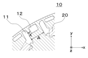
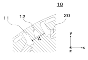
- FIG. 2 is an axial cross-sectional view showing one inter-pole hole of the rotor according to the first embodiment.
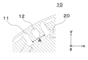
- FIG. 2 is an axial cross-sectional view showing an inter-pole hole 2 of a rotor according to embodiment 1.
- FIG. 1 is an axial cross-sectional view of an electric motor according to a first embodiment.
- 10 is a comparative diagram showing inter-pole holes of rotors in the first embodiment, the first comparative example, and the second comparative example.
- FIG. 4 shows numerical analysis data of iron loss of the electric motor in the first embodiment.
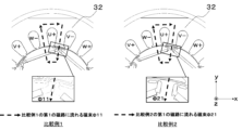
- FIG. 10 is a comparison diagram of a first magnetic path and a second magnetic path of a motor in Comparative Example 1.
- FIG. 10 is a comparison diagram of the first magnetic path of the electric motor in Comparative Example 1 and Comparative Example 2.
- FIG. 10 is a comparison diagram of a first magnetic path and a second magnetic path of electric motors in Comparative Example 1 and Comparative Example 2.
- FIG. 13 is a comparison diagram of the first magnetic path and the second magnetic path of the electric motor in the comparative example 2 and the first embodiment.
- FIG. 1 shows data on total loss in Comparative Example 1, Comparative Example 2, and Embodiment 1.
- 1 is a diagram illustrating a compressor to which the electric motor of each embodiment can be applied;
- 1 is a diagram illustrating a compression mechanism to which the electric motor of each embodiment can be applied;
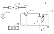
- FIG. 2 is a diagram showing a refrigeration cycle device having a compressor according to each embodiment during cooling operation.
- FIG. 2 is a diagram showing a refrigeration cycle device having a compressor according to each embodiment during heating operation.
- FIG. 11 is an axial cross-sectional view showing an inter-pole hole of a rotor according to a second embodiment.
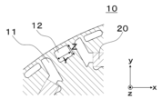
- FIG. 11 is an axial cross-sectional view showing an inter-pole hole of a rotor according to embodiment 3.
- FIG. 11 is an axial cross-sectional view showing an inter-pole hole of a rotor according to embodiment 4.
- FIG. 13 is an axial cross-sectional view showing an inter-pole hole of a rotor according to embodiment 5.
- FIG. 13 is an axial cross-sectional view showing an inter-pole hole of a rotor according to embodiment 6.
- FIG. 13 is an axial cross-sectional view showing an inter-pole hole of a rotor according to embodiment 7.
- 13 is an axial cross-sectional view showing an inter-pole hole of a rotor according to embodiment 8.
- FIG. 13 is an axial cross-sectional view showing an inter-pole hole of a rotor according to embodiment 9.
- FIG. 23 is an axial cross-sectional view showing an inter-pole hole of a rotor according to embodiment 10.
- Embodiment 1 the rotor 1, the stator 2, the electric motor 3, the compressor 4, and the refrigeration cycle device 5 according to the first embodiment will be described in detail with reference to the drawings.
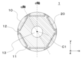
- ⁇ Rotor configuration> 1 is a cross-sectional view of a rotor 1 according to the embodiment 1.
- the rotor 1 shown in FIG. 1 is a cross-sectional view of a rotor 1 according to the embodiment 1. The rotor 1 shown in FIG.
- the direction along the circumference of a circle centered on axis C1, which is the center of rotation of rotor 1 is referred to as the "circumferential direction”
- the direction of axis C1 is referred to as the "axial direction”
- the direction of a line passing through rotor 1 perpendicular to the axial direction is referred to as the "radial direction”.
- an xyz Cartesian coordinate system is shown in the drawings to facilitate understanding of the drawings.
- the z-axis is a coordinate axis parallel to axis C1 of rotor 1.
- the y-axis is a coordinate axis perpendicular to the z-axis.
- the x-axis is a coordinate axis perpendicular to both the y-axis and the z-axis.
- the definitions of directions are the same not only in FIG. 1, but also in FIGS. 2 to 6, 8 to 11, and 17 to 25.
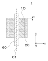
- Figure 2 is a cross-sectional view of the rotor 1 perpendicular to the radial direction.
- the rotor core 10 is cylindrical and centered on the axis C1, and is constructed by laminating multiple electromagnetic steel sheets with a thickness t in the axial direction and fastening them together with rivets and caulking (not shown).
- the thickness t is, for example, 0.1 to 0.7 mm.
- the rotor core 10 has magnet insertion holes 11, inter-pole holes 12, and shaft holes 13 that run through it in the axial direction.
- One or more magnet insertion holes 11 are provided on the d-axis, and permanent magnets 20 are inserted into the magnet insertion holes 11 to form magnetic poles.
- the d-axis refers to the axis that extends from the axis C1 of the rotor 1 in the direction of the magnetic flux created by the permanent magnets 20, as shown in Figure 1.
- six magnet insertion holes 11 are provided, but the number of magnet insertion holes 11 is not limited to six, and it is sufficient to have two or more.
- the shaft hole 13 is a hole into which the crankshaft 60 (not shown) is inserted. Details of the crankshaft 60 are explained in ⁇ Compressor configuration>.
- the permanent magnets 20 are made of rare earth magnets whose main components are neodymium (Nd), iron (Fe), and boron (B), or ferrite magnets whose main component is iron oxide (FeO). Either rare earth magnets or ferrite magnets may be used, but the energy product (product of magnetic flux density B and magnetic field H), which is one index of the performance of the permanent magnets 20, is higher for rare earth magnets than for ferrite magnets. Therefore, in order to ensure the same efficiency of the motor 3 for both, the volume of the permanent magnets 20 can be reduced with rare earth magnets compared to ferrite magnets. Therefore, rare earth magnets are used in this embodiment 1, and the space for providing the inter-pole holes 12 in the rotor core 10 can be expanded, improving the design freedom of the inter-pole holes 12.
- the permanent magnets 20 are arranged at regular intervals around the rotor core 10. In FIG. 1, one permanent magnet 20 is provided for each magnet insertion hole 11, but two or more permanent magnets 20 may be provided for each magnet insertion hole 11.
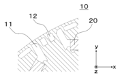
- ⁇ Relationship between X and t (t ⁇ X)> 3 is an enlarged cross-sectional view of the inter-pole hole 12. If the minimum circumferential distance between the magnet insertion hole 11 and the inter-pole hole 12 is X and the sheet thickness of the electromagnetic steel sheet is t, then t ⁇ X is satisfied.
- the rotor core 10 is constructed by punching electromagnetic steel sheets with a press die, forming punched holes, and then stacking them in the axial direction. If the distance between the magnet insertion holes 11 and the inter-pole holes 12 provided in the rotor core 10 is short, the rotor core 10 located between the magnet insertion holes 11 and the inter-pole holes 12 is easily deformed during punching. This deformation makes it difficult for magnetic flux to pass through the rotor core 10, resulting in a deterioration in motor efficiency.
- a method is available in which a holding mechanism is provided in the press die and the rotor core 10 is held and punched. However, the addition of a holding mechanism increases the number of punching processes for the rotor core 10, which increases the cycle time for manufacturing the rotor core 10 and causes a decrease in productivity.
- the rotor 1 is composed of a rotor core 10 and permanent magnets 20.
- the rotor core 10 is constructed by stacking electromagnetic steel sheets of thickness t in the axial direction (see FIG. 2), and has multiple magnet insertion holes 11 and one or more inter-pole holes 12 between the magnetic poles. If the minimum circumferential distance between the magnet insertion holes 11 and the inter-pole holes 12 is X and the thickness of the electromagnetic steel sheets is t, then the rotor 1 is configured to satisfy t ⁇ X. Note that while FIG. 3 shows one inter-pole hole 12, it may also have two or more inter-pole holes 12 as shown in FIG. 4.
- the rotor 1 according to the first embodiment is configured to satisfy t ⁇ X, thereby suppressing deformation of the rotor core 10 that occurs during punching, and improving the productivity of the rotor core 10.
- Fig. 5 is an axial cross-sectional view showing an example of an electric motor 3 equipped with the rotor 1 according to the present embodiment 1.
- the electric motor 3 shown in Fig. 5 is composed of a circular stator 2 and the rotor 1 arranged on the inner diameter side of the stator with a gap of 0.25 to 1.25 mm therebetween.
- the stator 2 is composed of a stator core 30, multiple windings (not shown), and multiple insulating papers (not shown).
- the stator core 30 is annular about the axis C1, and is constructed by stacking multiple electromagnetic steel sheets with a thickness of 0.1 to 0.7 mm in the axial direction and fastening them by crimping.
- the stator core 30 also includes an annular back yoke 32 and multiple teeth 31 that protrude radially inward from the back yoke 32. Furthermore, slots 33 are formed between the teeth 31 in the circumferential direction, which are spaces for inserting windings.
- four D-cuts 34 are provided on the outer circumferential surface of the back yoke 32, penetrating it in the axial direction. The number of D-cuts 34 is not limited to four, and it is sufficient that there is one or more.
- the teeth 31 are arranged at regular intervals around the stator core 30, and in this embodiment 1, 18 teeth 31 are provided.
- the number of teeth 31 is not limited to 18, and it is sufficient that there are two or more.
- the windings are formed by winding a conductor (not shown) made of a conductor mainly composed of copper (Cu) or aluminum (Al) and an insulating coating (not shown) that covers the outer circumference of the conductor around the teeth 31.
- the main component of the conductor is not limited to copper (Cu) or aluminum (Al), but may be silver (Ag) or iron (Fe).
- copper (Cu) and aluminum (Al) are cheaper to procure than silver (Ag).
- copper (Cu) and aluminum (Al) have lower resistivity than iron (Fe), so the loss in the windings is reduced and the efficiency of the motor 3 can be improved. Therefore, by forming the conductor of the windings in this embodiment 1 from copper (Cu) or aluminum (Al), an inexpensive and highly efficient motor can be constructed.
- the winding is composed of concentrated winding or distributed winding.
- Concentrated winding has a winding on one tooth 31, so the axial height of the coil end (not shown) can be reduced, and the motor 3 can be made smaller.
- Distributed winding has a winding across multiple teeth 31, so the coil end is characterized by being higher in the axial direction.
- distributed winding has a feature that it is easier to secure a magnetic path for the q-axis magnetic flux passing through the rotor core 10 because multiple teeth 31 form one magnetic pole, and the q-axis inductance Lq is improved.
- the insulating paper is, for example, a polyethylene terephthalate film (polyester film).
- the insulating paper is used to insulate the slots 33 of the stator 2, between the phases of the windings, and at the coil ends.
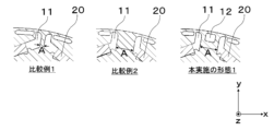
- FIG. 6 is a cross-sectional view showing the rotor core 10 of Comparative Example 1, Comparative Example 2, and the present embodiment 1.
- the inter-pole holes 12 are not provided.
- the inter-pole holes 12 are provided in Comparative Example 2.
- the radial length of the inter-pole hole 12 is 2 [mm]
- the circumferential length of the inter-pole hole 12 is 2.5 [mm].
- the number of pole pairs is Pn
- the d-axis inductance is Ld [H]
- the q-axis inductance is Lq [H]
- the d-axis current is id [A]
- the q-axis current is iq [A]
- the magnitude of the current vector is Ia [A]
- the leading phase angle of the current vector from the q-axis is ⁇ [deg].
- the reluctance torque Tr is expressed by the following formula 1.
- Equation 1 As can be seen from Equation 1, as (Lq - Ld) increases, the reluctance torque Tr increases. Also, the reluctance torque Tr increases in proportion to the square of the current vector Ia.
- magnet torque Tm is also used.
- an attractive force and a repulsive force are generated between the stator 2 and the permanent magnet 20. These attractive and repulsive forces are the magnet torque Tm.
- the magnet torque Tm is expressed by the following formula 2.
- the torque T generated in the rotor 1 is a combination of the magnet torque Tm and the reluctance torque Tr.
- the torque T is expressed by the following equation 3.
- the magnet torque Tm increases in proportion to the current vector Ia
- the reluctance torque Tr increases in proportion to the square of the current vector Ia.
- the distribution of the magnet torque Tm increases, while when the motor 3 is operated at high torque, the distribution of the reluctance torque Tr increases.
- ⁇ Mechanism of iron loss reduction by inter-pole holes> 7 shows numerical analysis data of the iron loss generated in the motor 3 of Comparative Example 1, Comparative Example 2, and the present embodiment 1.
- the rotation speed of the motor 3 is set to 60 [rps]
- the torque of the motor 3 is set to 13.6 [Nm].
- the iron loss generated in the stator core 30 (hereinafter, "stator iron loss”) is increased by 4.4 [W] in Comparative Example 2 compared to Comparative Example 1.
- the iron loss generated in the rotor core 10 (hereinafter, “rotor iron loss”) is increased by 5.5 [W] in Comparative Example 2 compared to Comparative Example 1.
- the iron loss generated in the sealed container 90 of the compressor 4 (hereinafter, “compressor iron loss”) is increased by 2.7 [W] in Comparative Example 2 compared to Comparative Example 1.
- the reason for the increase in stator iron loss in Comparative Example 2 is that the armature magnetic flux passes more easily in the q-axis direction of the rotor core 10, resulting in a higher magnetic flux density in the back yoke 32 of the stator 2.
- the reason for the increase in rotor iron loss in Comparative Example 2 is that the iron loss generated between the magnet insertion holes 11 increases.
- the reason for the increase in compressor iron loss in Comparative Example 2 will be described later, but this is because the magnetic flux density of the back yoke 32 increases in Comparative Example 2 compared to Comparative Example 1, making it difficult for magnetic flux to flow through the back yoke 32. In other words, in Comparative Example 2, magnetic flux leaks more easily into the sealed container 90 of the compressor 4, resulting in an increase in compressor iron loss generated in the sealed container 90 of the compressor 4.
- inter-pole hole a rectangular gap (hereinafter, "inter-pole hole") in the rotor core 10 between adjacent magnetic poles as in the present embodiment 1, the armature magnetic flux is reduced compared to the comparative example 2. Due to the effect of this inter-pole hole 12, the magnetic flux density generated in the back yoke 32 of the stator 2 is reduced in the present embodiment 1 compared to the comparative example 2, so that the stator iron loss generated in the back yoke 32 can be reduced.
- Figure 8 is an example of an electric motor 3 of Comparative Example 1.
- the number of slots 33 in the stator 2 is 18, the number of poles in the rotor 1 is 6, and the winding is an example of distributed winding wound across multiple teeth 31.
- three teeth 31 of the stator 2 face one magnetic pole of the rotor 1.
- the stator 2 has three teeth 31 that form one magnetic pole.
- the armature magnetic flux generated from the two teeth 31 at both ends is defined as ⁇ 1
- the armature magnetic flux generated from the single central tooth 31 is defined as ⁇ 2.
- Figure 8 also clearly shows the definition of the magnetic path of the armature magnetic flux.
- the magnetic path through which ⁇ 1 passes is defined as the "first magnetic path”
- the magnetic path through which ⁇ 2 passes is defined as the "second magnetic path.”
- Figure 9 is a comparison diagram of the first magnetic path in Comparative Example 1 and Comparative Example 2.
- the magnetic flux flowing through the first magnetic path in Comparative Example 1 is defined as ⁇ 11
- the magnetic flux flowing through the first magnetic path in Comparative Example 2 is defined as ⁇ 21.
- the interpole width A is enlarged compared to Comparative Example 1, so the magnetic resistance of the first magnetic path is smaller.
- the relationship between the magnetic flux flowing through the first magnetic path in both Comparative Example 1 and Comparative Example 2 is ⁇ 11 ⁇ ⁇ 21. Due to this effect, the magnetic flux density in the back yoke 32 is higher in Comparative Example 2 than in Comparative Example 1.
- FIG. 10 is a comparison diagram of the first and second magnetic paths in Comparative Example 1 and Comparative Example 2.
- the magnetic flux flowing through the second magnetic path in Comparative Example 1 is defined as ⁇ 12
- the magnetic flux flowing through the second magnetic path in Comparative Example 2 is defined as ⁇ 22.
- the magnetic flux density of the back yoke 32 in Comparative Example 1 is defined as B1
- the magnetic flux density of the back yoke 32 in Comparative Example 2 is defined as B2.
- the magnetic flux ⁇ 21 of the first magnetic path in Comparative Example 2 increases compared to the magnetic flux ⁇ 11 of the first magnetic path in Comparative Example 1, so the magnetic flux density of the back yoke 32 is B1 ⁇ B2.
- the magnetic permeability of the back yoke 32 in Comparative Example 2 is lower than that of Comparative Example 1, and magnetic flux becomes less likely to flow in this back yoke 32. Therefore, the magnetic flux ⁇ 22 of the second magnetic path in Comparative Example 2 becomes less likely to flow through the back yoke 32 compared to the magnetic flux ⁇ 12 of the second magnetic path in Comparative Example 1.
- the magnetic flux density of the back yoke 32 in Comparative Example 2 is higher than that in Comparative Example 1 (B1 ⁇ B2), making it difficult for magnetic flux to flow through the back yoke 32.
- the iron loss generated in the back yoke 32 increases in Comparative Example 2.
- the magnetic flux ⁇ 22 of the second magnetic path is more likely to leak into the sealed container 90 of the compressor 4, so the compressor iron loss generated in the sealed container 90 of the compressor 4 increases.
- inter-pole holes 12 are provided, as shown in the present embodiment 1 in FIG. 6.
- FIG. 11 is a comparison diagram of the first and second magnetic paths in Comparative Example 2 and the present embodiment 1.
- the magnetic flux flowing through the first magnetic path in the present embodiment 1 is defined as ⁇ 31
- the magnetic flux flowing through the second magnetic path in the present embodiment 1 is defined as ⁇ 32
- the magnetic flux density of the back yoke 32 in the present embodiment 1 is defined as B3.
- the interpole hole 12 is provided. Therefore, the magnetic resistance of the first magnetic path is higher in the present embodiment 1 than in the comparative example 2. That is, the magnetic flux ⁇ 31 flowing through the first magnetic path in the present embodiment 1 is reduced compared to the magnetic flux ⁇ 21 flowing through the first magnetic path in the comparative example 2, so that ⁇ 21> ⁇ 31. For this reason, the magnetic flux density in the back yoke 32 can be lowered in the present embodiment 1 than in the comparative example 2, and B2>B3.
- ⁇ Loss Reduction Effect of First Embodiment> 12 shows numerical analysis data of losses generated in the electric motor 3 of Comparative Example 1, Comparative Example 2, and the present embodiment 1.
- the rotation speed of the electric motor 3 was set to 60 [rps]
- the torque of the electric motor 3 was set to 13.6 [Nm].
- the electric motor 3 of the present embodiment 1 has reduced copper loss and iron loss due to improved reluctance torque compared to the comparative example 1.
- FIG. 13 is a cross-sectional view showing an example of the compressor 4 equipped with the electric motor 3 according to the first embodiment.
- the compressor 4 is, for example, a rotary compressor. Note that the compressor 4 is not limited to a rotary compressor, and may be another compressor such as a low-pressure compressor or a scroll compressor.
- the compressor 4 has an electric motor 3, a crankshaft 60 as a rotating shaft, a compression mechanism 70, and a sealed container 90.
- the electric motor 3 drives the compression mechanism 70.
- the compression mechanism 70 compresses the refrigerant sucked from the accumulator 111.
- the configuration of the compression mechanism 70 will be described later.
- the crankshaft 60 connects the electric motor 3 and the compression mechanism 70.
- the crankshaft 60 has a shaft main body 60a that is fixed to the rotor 2 of the electric motor 3, and an eccentric shaft 60b that is fixed to the rolling piston 80 of the compression mechanism 70.
- the sealed container 90 is cylindrical and houses the electric motor 3 and the compression mechanism 70.
- Refrigeration oil is stored in an oil reservoir at the bottom of the sealed container 90.
- the refrigeration oil is a lubricant that lubricates the sliding parts of the compression mechanism 70 (for example, the mating part between the rolling piston 80 and the eccentric shaft 60b).
- the refrigeration oil passes through an oil supply passage formed inside the crankshaft 60 to lubricate the sliding parts of the compression mechanism 70.
- the compressor 4 further has a discharge pipe 91 and a terminal 92 attached to the top of the sealed container 90.
- the discharge pipe 91 discharges the refrigerant compressed by the compression mechanism 70 to the outside of the sealed container 90.
- the discharge pipe 91 is connected to the refrigerant circuit shown in FIG. 15 or FIG. 16.
- the terminal 92 is connected to a drive device (not shown) that is provided outside the compressor 4.
- the terminal 92 also supplies a drive current to the windings of the stator 2 of the electric motor 3 via the lead wire 93. This causes the rotor 1 of the electric motor 3 to rotate.
- FIG. 14 is a cross-sectional view showing the configuration of the compression mechanism 70.
- the compression mechanism 70 has a cylinder 71, a rolling piston 80, a vane 81, an upper bearing 82, and a lower bearing 84.
- the cylinder 71 has an intake port 71a, a cylinder chamber 71b, and a vane groove 71c.
- the intake port 71a is connected to the accumulator 111 via an intake pipe 72.
- the intake port 71a is a passage through which the refrigerant drawn from the accumulator 111 flows, and is connected to the cylinder chamber 71b.
- the direction along the circumference of a circle centered on the crankshaft 60 is called the "circumferential direction”
- the direction of the axis C1 which is the center of rotation of the crankshaft 60 is called the "axial direction”
- the direction of a straight line passing through the crankshaft 60 perpendicular to the axial direction is called the "radial direction”.
- an xyz Cartesian coordinate system is shown in the drawings to facilitate understanding of the drawings.
- the z-axis is a coordinate axis parallel to the axis C1 of the crankshaft 60.
- the y-axis is a coordinate axis perpendicular to the z-axis.
- the x-axis is a coordinate axis perpendicular to both the y-axis and the z-axis.
- the cylinder chamber 71b is a cylindrical space centered on the axis C1.
- the cylinder chamber 71b houses the eccentric shaft portion 60b of the crankshaft 60, the rolling piston 80, and the vane 81.
- the rolling piston 80 When viewed in the z-axis direction, the rolling piston 80 has a ring-like shape.
- the rolling piston 80 is fixed to the eccentric shaft portion 60b of the crankshaft 60.
- the vane groove 71c communicates with the cylinder chamber 71b.
- a vane 81 is attached to the vane groove 71c.
- a back pressure chamber 71d is formed at the end of the vane groove 71c.
- the vane 81 is pressed toward the axis C1 by a spring (not shown) arranged in the back pressure chamber 71d, and thus contacts the outer circumferential surface of the rolling piston 80.
- the vane 81 divides the space 86 surrounded by the inner circumferential surface of the cylinder chamber 71b, the outer circumferential surface of the rolling piston 80, the upper bearing portion 82, and the lower bearing portion 84 into an intake side working chamber (hereinafter referred to as the "intake chamber”) 86a and a compression side working chamber (hereinafter referred to as the “compression chamber”) 86b.
- the intake chamber 86a communicates with the intake port 71a.
- the vane 81 When the rolling piston 80 rotates eccentrically, the vane 81 reciprocates in the vane groove 71c in the y-axis direction.
- the vane 81 is, for example, plate-shaped. Note that in the example shown in FIG. 14, the rolling piston 80 and the vane 81 are separate bodies, but the rolling piston 80 and the vane 81 may be integrated.
- the upper bearing portion 82 closes the end of the cylinder chamber 71b on the +z axis side.
- the lower bearing portion 84 closes the end of the cylinder chamber 71b on the -z axis side.
- the upper bearing portion 82 and the lower bearing portion 84 are each fixed to the cylinder 71 by fastening members (e.g., bolts) not shown.
- the upper bearing portion 82 and the lower bearing portion 84 each have a discharge port that discharges the compressed refrigerant to the outside of the cylinder chamber 71b.
- the discharge ports of the upper bearing portion 82 and the lower bearing portion 84 are connected to the compression chamber 86b of the cylinder chamber 71b.
- the discharge ports are provided with a discharge valve (not shown). The discharge valve opens when the pressure of the refrigerant compressed in the compression chamber 86b reaches or exceeds a predetermined pressure, and discharges the high-temperature, high-pressure refrigerant into the internal space of the sealed container 90.
- the lower bearing portion 84 does not necessarily have to have a discharge port.
- the upper bearing portion 82 is attached to the upper discharge muffler 83 by a fastening member (e.g., a bolt).
- a muffler chamber 83a is provided between the upper bearing portion 82 and the upper discharge muffler 83. This allows the refrigerant discharged from the discharge port of the upper bearing portion 82 to diffuse into the muffler chamber 83a, thereby suppressing the generation of discharge noise of the refrigerant discharged from the discharge port of the upper bearing portion 82.
- a lower discharge muffler 85 is attached to the lower bearing portion 84 by a fastening member (e.g., a bolt).
- a muffler chamber 85a is provided between the lower bearing portion 84 and the lower discharge muffler 85. This allows the refrigerant discharged from the discharge port of the lower bearing portion 84 to diffuse into the muffler chamber 85a, thereby suppressing the generation of discharge noise of the refrigerant discharged from the lower bearing portion 84.
- the discharge muffler may be provided in the frame in which the discharge port is formed.
- ⁇ Refrigeration cycle device> 15 and 16 are external views showing an example of a refrigeration cycle apparatus 5 equipped with the compressor 4 according to the embodiment 1.
- a case in which the refrigeration cycle apparatus 5 is applied to an air-conditioning apparatus will be described as an example.
- the refrigeration cycle apparatus 5 may be applied to other apparatuses such as a refrigerator or a heat pump cycle apparatus.
- FIG. 15 is a diagram showing the configuration of the refrigerant circuit during cooling operation of the refrigeration cycle device 5 according to the first embodiment.
- FIG. 16 is a diagram showing the configuration of the refrigerant circuit during heating operation of the refrigeration cycle device 5 according to the first embodiment.
- the refrigeration cycle device 5 has a refrigerant, a compressor 4 that compresses the refrigerant, an accumulator 111, a four-way valve 112 that switches between cooling operation and heating operation, an outdoor heat exchanger 113, an expansion valve 114 as a pressure reducing device, an indoor heat exchanger 115, and piping 116.
- the compressor 4, the accumulator 111, the outdoor heat exchanger 113, the expansion valve 114, and the indoor heat exchanger 115 are connected to each other by piping (e.g., copper pipes) 116.
- the compressor 4, the outdoor heat exchanger 113, the expansion valve 114, and the indoor heat exchanger 115 form a refrigerant circuit.
- the refrigeration cycle device 5 further includes a control unit 117.
- the control unit 117 controls, for example, the pressure or temperature inside the compressor 4.
- the control unit 117 is, for example, a microcomputer.
- the control unit 117 may also control other elements constituting the refrigeration cycle device 5 (for example, the four-way valve 112, etc.).
- the compressor 4 compresses the refrigerant sucked from the accumulator 111 and sends it out as high-temperature, high-pressure refrigerant gas.
- the four-way valve 112 passes the high-temperature, high-pressure refrigerant gas sent out from the compressor 4 to the outdoor heat exchanger 113.
- the outdoor heat exchanger 113 exchanges heat between the high-temperature, high-pressure refrigerant gas and a medium (e.g., air) to condense the refrigerant gas and send it out as low-temperature, high-pressure liquid refrigerant.
- the outdoor heat exchanger 113 functions as a condenser.
- the expansion valve 114 expands the liquid refrigerant sent from the outdoor heat exchanger 113 and sends it out as low-temperature, low-pressure liquid refrigerant. Specifically, the low-temperature, high-pressure liquid refrigerant sent out from the outdoor heat exchanger 113 is decompressed by the expansion valve 114, becoming a two-phase state of low-temperature, low-pressure refrigerant gas and low-temperature, low-pressure liquid refrigerant.
- the indoor heat exchanger 115 exchanges heat between the two-phase refrigerant sent out from the expansion valve 114 and a medium (e.g., air), evaporates the liquid refrigerant, and sends out the refrigerant gas.
- a medium e.g., air
- the indoor heat exchanger 115 functions as an evaporator.
- the refrigerant gas sent out from the indoor heat exchanger 115 returns to the compressor 4 via the accumulator 111.
- the refrigerant circulates through the refrigerant circuit along the path indicated by the arrows in FIG. 15.
- the refrigerant circulates through the compressor 4, the outdoor heat exchanger 113, the expansion valve 114, and the indoor heat exchanger 115 in that order.
- the cooling operation and heating operation are switched by switching the flow path with the four-way valve 112 as shown in Figures 15 and 16.
- the indoor heat exchanger 115 functions as a condenser and the outdoor heat exchanger 113 functions as an evaporator.
- the refrigerant is a mixed refrigerant containing ethylenic fluorohydrocarbons having carbon double bonds.
- a mixed refrigerant containing ethylenic fluorohydrocarbons having carbon double bonds By using a mixed refrigerant containing ethylenic fluorohydrocarbons having carbon double bonds, the operating pressure can be reduced and disproportionation reactions can be prevented.
- the refrigerant is a mixed refrigerant containing R1123. Note that the refrigerant is not limited to R1123, and may be a mixed refrigerant containing other ethylenic fluorohydrocarbons.
- the refrigerant may contain one or more types of ethylene-based fluorohydrocarbons, and may be a mixed refrigerant made by mixing an ethylene-based fluorohydrocarbon with another refrigerant.
- the refrigerant may be a mixed refrigerant made by mixing R1123 and R32.
- the ratio of R1123 in this mixed refrigerant is preferably set within the range of 40 wt% to 60 wt%, for example.
- R1123 is not limited to R32, and may be mixed with one or more of the following refrigerants: R1234yf, R1234ze(E), R1234ze(Z), R125, and R134a.
- the refrigerant may also be a refrigerant having two or more types of ethylenic fluorocarbons.
- R1123 may be mixed with one or more of the ethylenic fluorocarbons R1141, R1132a, R1132(E), and R1132(Z).
- the refrigerant may be a mixed refrigerant of R516A, R445A, R444A, R454C, R444B, R454A, R455A, R457A, R459B, R452B, R454B, R447B, R447A, R446A, and R459A.
- the other refrigerant may be a single refrigerant such as R1234yf, R1234ze, R32, or R290.
- Embodiment 2. ⁇ Relationship between X and t (2t ⁇ X ⁇ (A ⁇ 1) ⁇ 0.5)> 17 is an enlarged view of a cross section of inter-pole hole 12 in embodiment 2. If the minimum circumferential distance between magnet insertion holes 11 is A and the sheet thickness of the electromagnetic steel sheet is t, the range of minimum circumferential distance X between magnet insertion hole 11 and inter-pole hole 12 satisfies 2t ⁇ X ⁇ (A-1) ⁇ 0.5.
- the rotor core 10 is constructed by punching electromagnetic steel sheets using a press die to form punched holes, which are then stacked in the axial direction.
- the magnetic properties of the rotor core 10 around the end faces 1 of the punched holes are degraded.
- Degradation of magnetic properties means that the magnetic permeability of the core is reduced.
- degradation of magnetic properties occurs at a distance from the end faces of the punched holes equivalent to the sheet thickness t of the electromagnetic steel sheets.
- the rotor core 10, in which the inter-pole holes 12 are provided is the q-axis magnetic path. If the magnetic flux in the q-axis magnetic path flows easily, the q-axis inductance Lq increases. Therefore, according to Equation 3, in order to increase the reluctance torque Tr, it is necessary to increase the q-axis inductance Lq, so it is desirable for the q-axis magnetic path to be one in which magnetic flux flows easily. However, after the inter-pole holes 12 are punched, the magnetic properties around the end faces of the inter-pole holes 12 deteriorate, leading to a decrease in the q-axis inductance Lq.
- the minimum distance X between the magnet insertion hole 11 and the inter-pole hole 12 is related to the thickness t of the electromagnetic steel sheet that constitutes the rotor core 10, such that 2t ⁇ X.
- Deterioration of magnetic properties occurs within a distance t from the end faces of the magnet insertion hole 11 and the inter-pole hole 12. Therefore, by determining the shape of the inter-pole hole 12 so that there is a relationship of 2t ⁇ X, it is possible to provide a q-axis magnetic path in which deterioration of magnetic properties does not occur. This allows the inter-pole hole 12 to be provided without reducing the q-axis inductance Lq, thereby improving the reluctance torque Tr.
- the minimum circumferential distance of the inter-pole holes 12 is 1 mm or more.
- the rotor core 10 is made by punching an electromagnetic steel sheet using a press die to form the punched holes. At this time, if the width of the punch used in the press die is short, the durability of the die is deteriorated, leading to a shortened lifespan of the production equipment. In general, by ensuring that the width of the punched holes formed in the rotor core 10 is 1 mm or more, the durability of the die can be ensured. To satisfy this, the range of the minimum circumferential distance X between the magnet insertion holes 11 and the inter-pole holes 12 is set to satisfy the relationship X ⁇ (A-1) ⁇ 0.5.
- Embodiment 3. ⁇ Relationship between Y and t (1 ⁇ Y ⁇ A-2t)> 18 is an enlarged view of a cross section of inter-pole holes 12 in embodiment 3. If the minimum circumferential distance between magnet insertion holes 11 is A and the sheet thickness of the electromagnetic steel sheet is t, the range of the minimum circumferential distance Y of inter-pole holes 12 satisfies 1 ⁇ Y ⁇ A-2t.
- the durability of the mold can be ensured by setting the minimum circumferential distance of the inter-pole holes 12 formed in the rotor core 10 to 1 mm or more.
- the range of the minimum circumferential distance Y of the inter-pole holes 12 is set to have a relationship of 1 ⁇ Y.
- the distance between the magnet insertion holes 11 and the inter-pole holes 12 can be ensured to be equal to or greater than the thickness t of the electromagnetic steel sheet.
- the rotor core 10 is more likely to deform during punching, which is a factor in reducing productivity. Therefore, by configuring the minimum radial distance X between the magnet insertion holes 11 and the inter-pole holes 12 to be equal to or greater than the thickness t of the electromagnetic steel sheet, the productivity of the rotor core 10 can be improved.
- the range of the minimum circumferential distance Y of the inter-pole holes 12 is set to satisfy the relationship Y ⁇ A-2t.
- Embodiment 4. ⁇ Relationship between T1 and T2 (t ⁇ T1 ⁇ T2)> 19 is an enlarged cross-sectional view of inter-pole hole 12 in embodiment 4. If the minimum radial distance between magnet insertion hole 11 and the outer circumferential surface of rotor core 10 is T1, and the minimum radial distance between inter-pole hole 12 and the outer circumferential surface of rotor core 10 is T2, then t ⁇ T1 ⁇ T2 is satisfied.
- the productivity of the rotor core 10 can be improved.
- the range of the minimum radial distance T1 between the magnet insertion holes 11 and the outer peripheral surface of the rotor core 10 is set so that t ⁇ T1.
- the magnetic resistance of the inter-pole hole 12 is lowered relative to the magnet insertion hole 11, making it easier for the q-axis magnetic flux to flow in the magnetic path in which the inter-pole hole 12 is provided.
- the magnetic path of the magnetic flux flowing on the q-axis can be properly secured, improving the q-axis inductance Lq and increasing the reluctance torque Tr.
- the range of the minimum radial distance T2 between the inter-pole hole 12 and the outer circumferential surface of the rotor core 10 is set to have the relationship T1 ⁇ T2.
- Embodiment 5 ⁇ Relationship between Y and Z (Y ⁇ Z)> 20 is an enlarged cross-sectional view of the inter-pole hole 12 in the present embodiment 5. If the minimum distance of the inter-pole hole 12 in the circumferential direction is Y and the minimum distance of the inter-pole hole 12 in the radial direction is Z, then Y ⁇ Z is satisfied.
- the magnetic path of the magnetic flux flowing on the q-axis can be properly secured, improving the q-axis inductance Lq and increasing the reluctance torque Tr.
- the minimum radial distance of the inter-pole holes 12 is Z
- the range of the minimum circumferential distance Y of the inter-pole holes 12 is set to satisfy the relationship Y ⁇ Z.
- the rotor 1 is configured such that Y ⁇ Z, so that the reluctance torque Tr can be increased and the efficiency of the electric motor 3 can be improved.
- Embodiment 6 ⁇ Relationship between Y and Z (Y>Z)> 21 is an enlarged view of a cross section of the inter-pole hole 12 in the present embodiment 6. If the minimum distance of the inter-pole hole 12 in the circumferential direction is Y and the minimum distance of the inter-pole hole 12 in the radial direction is Z, then Y>Z is satisfied.
- the minimum circumferential distance Y of the inter-pole holes 12 is increased, the magnetic flux flowing along the q-axis decreases, and the magnetic flux flowing through the back yoke 32 decreases, thereby reducing the magnetic flux density of the back yoke 32 and reducing the iron loss generated in the stator core 30.
- the range of the minimum circumferential distance Y of the inter-pole holes 12 has the relationship Y>Z.
- Embodiment 7 ⁇ Iron cores are evenly spaced between magnet insertion holes and inter-pole holes> 22 is an enlarged view of a cross section of the inter-pole hole 12 in the seventh embodiment.
- the circumferential centers of the magnet insertion holes 11 coincide with the q axis, and the center of the circumferential width of the inter-pole hole 12 also coincides with the q axis.
- the magnetic flux density in that magnetic path is uniform. This makes it possible to prevent the magnetic flux density from becoming locally high in the magnetic path between the magnet insertion holes 11 and the inter-pole holes 12, and therefore increases the magnetic permeability in this magnetic path. As a result, the magnetic path of the magnetic flux flowing on the q-axis can be appropriately secured, improving the q-axis inductance Lq and increasing the reluctance torque Tr.
- Embodiment 8 ⁇ Numerical range of R (0.2 ⁇ R ⁇ Y ⁇ 0.5)> 23 is an enlarged cross-sectional view of the inter-electrode hole 12 in the present embodiment 8.
- R radius of the roundness provided at the corner of the inter-electrode hole 12
- the relation 0.2 ⁇ R ⁇ Y ⁇ 0.5 is satisfied.
- the range of the radius R of the rounding provided at the corners is set to 0.2 ⁇ R. This makes it possible to alleviate the tensile stress generated at the corners of the inter-pole holes 12 and improve the mechanical strength of the rotor core 10.
- Embodiment 9 ⁇ The shape of the inter-electrode hole is triangular> 24 is an enlarged cross-sectional view of the inter-pole hole 12 in the present embodiment 9.
- the inter-pole hole 12 is configured in a triangular shape having an apex on the radially outer side of the rotor core 10.
- the inter-pole hole 12 By forming the inter-pole hole 12 as a triangle with a vertex on the radial outside of the rotor core 10, the magnetic resistance on the radial outside of the inter-pole hole 12 is reduced, making it easier for the q-axis magnetic flux to flow. In other words, the magnetic path of the magnetic flux flowing on the q-axis can be properly secured, improving the q-axis inductance Lq and increasing the reluctance torque Tr.
- the inter-pole hole 12 is configured in the shape of a triangle having an apex on the radially outer side, whereby the reluctance torque Tr can be increased, and the effect of increasing the efficiency of the electric motor 3 can be achieved.
- Embodiment 10 ⁇ Circular or elliptical shape of the inter-electrode hole> 25 is an enlarged cross-sectional view of the inter-electrode hole 12 in the present embodiment 10.
- the inter-electrode hole 12 is configured to have a perfect circle shape or an ellipse shape extending in the radial direction.
- the refrigerant circulates in the compression mechanism 70 of the compressor 4, so the refrigerant also passes through the rotor 1 in the axial direction. Therefore, it is desirable to provide a gap in the axial direction of the rotor core 10 to be used as a refrigerant flow path. Furthermore, if the cross-sectional area of the refrigerant flow path as viewed in the axial direction is large and the circumferential length of the end face forming the refrigerant flow path is short, the flow path resistance of the refrigerant is reduced, allowing the refrigerant to pass through the refrigerant flow path efficiently.
- a perfect circle or ellipse is desirable as the shape of the refrigerant flow passage in order to shorten the circumferential length of the end face.
- a magnetic path located between the magnet insertion hole 11 and the inter-pole hole 12 is secured, making it easier for the q-axis magnetic flux to flow.
- the q-axis inductance Lq is improved, and the reluctance torque Tr can be increased.
Landscapes
- Engineering & Computer Science (AREA)
- Power Engineering (AREA)
- Iron Core Of Rotating Electric Machines (AREA)
Abstract
電動機の主要部材である電磁鋼板、永久磁石、巻線の使用量を増加させずにリラクタンストルクを向上させ、また回転子鉄心の生産性を低下させることなく、電動機の高効率化を達成することができる回転子を得る。 回転子は、回転子鉄心と永久磁石で構成されており、前記回転子鉄心は板厚tの電磁鋼板を軸方向に積層して構成され、複数の磁石挿入孔を備え、磁極同士の間には1以上の極間孔を備え、磁石挿入孔と極間孔との周方向の最小距離をXとし、電磁鋼板の板厚をtとした場合、t≦Xを満足するように構成したものである。
Description
本発明は、回転子、電動機、圧縮機、および冷凍サイクル装置に関するものである。
近年、省エネルギー基準の達成に向けて競争の著しい電気自動車や空調機において、製品の消費電力削減のため、電動機の高効率化が強く要求されている。
電動機の高効率化のためには、永久磁石の使用量を増やして磁力を増加させ、巻線に発生する銅損を低減することが考えられる。しかし、電動機の主要構成要素である電磁鋼板、永久磁石および巻線の資源確保のリスクが高いため、電動機を構成する素材の使用量増加を招くことは望ましくない。
そのため、電動機の主要部材である電磁鋼板、永久磁石、巻線の使用量を増加させずに、高効率化を達成することが求められている。
上記を達成するための手段として、固定子と永久磁石の相互作用によって発生するマグネットトルクだけでなく、固定子と回転子の相互作用によって発生するリラクタンストルクを活用することが考えられる。リラクタンストルクを活用することによって電動機に発生するトルクを高めることが可能となり、巻線に発生する銅損を低減し、電動機の効率を向上させることができる。
電動機のリラクタンストルクを有効的に活用するための方法としては、磁極同士の間(以下:「極間」)に孔(以下:「極間孔」)を設ける構成が知られている(例えば、特許文献1)。
しかしながら、電動機は固定子鉄心および回転子鉄心をプレス金型にて打抜き、打抜き孔を形成した後、それを軸方向に積層して構成されている。回転子鉄心に設けられる磁石挿入孔と極間孔の距離が短いと、打抜き加工のときに回転子鉄心の生産性を低下させる要因となる。
本発明に係る回転子は、上記の課題を解決するためになされたものであり、電動機の主要部材である電磁鋼板、永久磁石、巻線の使用量を増加させずにリラクタンストルクを向上させ、また回転子鉄心の生産性を低下させることなく、電動機の高効率化を達成することができる回転子を提供することを目的とする。
上記の目的を達成するため、本発明に係る回転子は、回転子鉄心と永久磁石で構成されており、前記回転子鉄心は板厚tの電磁鋼板を軸方向に積層して構成され、複数の磁石挿入孔を備え、磁極同士の間には1以上の極間孔を備え、磁石挿入孔と極間孔との周方向の最小距離をXとし、電磁鋼板の板厚をtとした場合、t≦Xを満足するように構成したものである。
本発明に係る回転子は、磁石挿入孔と極間孔の径方向の最小距離Xを電磁鋼板の板厚t以上設けた構成とすることで、打抜き加工のときに生産性を低下させることなく、リラクタンストルクを向上させることができるので、電動機を高効率化することができる。
以下、図面を参照しながら本発明の実施の形態について説明する。以下の図面において同一または相当する部分には同一の参照番号を付し、その説明は繰り返さない。また、図1を含め以下の図面では、各構成部材の大きさの関係が実際のものと異なる場合がある。さらに、明細書全文に表されている構成要素の形態は、あくまで例示であって、これらの記載に限定されるものではない。
実施の形態1.
以下に、本実施の形態1に係る回転子1、固定子2、電動機3、圧縮機4、および冷凍サイクル装置5を図面に基づいて詳細に説明する。
以下に、本実施の形態1に係る回転子1、固定子2、電動機3、圧縮機4、および冷凍サイクル装置5を図面に基づいて詳細に説明する。
<回転子の構成>
図1は本実施の形態1に係る回転子1の断面図である。図1に示される回転子1は、円状の回転子鉄心10と複数の永久磁石20とにより構成される。
図1は本実施の形態1に係る回転子1の断面図である。図1に示される回転子1は、円状の回転子鉄心10と複数の永久磁石20とにより構成される。
以下の説明では、回転子1の回転中心である軸線C1を中心とする円の円周に沿った方向を「周方向」、軸線C1の方向を「軸方向」、軸方向に直交して回転子1を通る直線の方向を「径方向」と称する。また、図面には、図面相互の理解を容易にするために、xyz直交座標系が示されている。z軸は、回転子1の軸線C1に平行な座標軸である。y軸は、z軸に直交する座標軸である。x軸は、y軸およびz軸の両方に直交する座標軸である。図1のみならず、図2~図6、図8~図11および図17~図25においても方向の定義は共通する。
図2は、径方向に直交する回転子1の断面図である。回転子鉄心10は、軸線C1を中心とする円筒状であり、板厚tの電磁鋼板を軸方向に複数枚積層し、図示しないカシメとリベットとにより締結して構成される。板厚tは、例えば0.1~0.7[mm]である。
図1に示すように、回転子鉄心10には軸方向に貫通された磁石挿入孔11と極間孔12とシャフト孔13とが設けられる。
磁石挿入孔11は、d軸上に1以上設けられており、磁石挿入孔11には永久磁石20が挿入されて磁極を構成している。ここでd軸とは、図1に示すように回転子1の軸線C1から永久磁石20が作る磁束の方向に延びる軸のことである。図1では6個の磁石挿入孔11が設けられているが、磁石挿入孔11は6個に限らず2個以上備えていればよい。
極間孔12は、q軸上に1以上設けられている。ここでq軸とは、回転子1の軸線C1を中心にd軸から電気角90[°]ずれた位置にある軸のことである。電気角90[°]とは、極数Pの回転子1において、機械角180/P[°]に相当する。
シャフト孔13は、図示しないクランクシャフト60が挿入される孔である。クランクシャフト60の詳細は、<圧縮機の構成>にて説明する。
永久磁石20は、ネオジウム(Nd)と鉄(Fe)とホウ素(B)とを主成分とする希土類磁石や、酸化鉄(FeO)を主成分とするフェライト磁石が用いられる。希土類磁石もしくはフェライト磁石の何れかを備えていればよいが、永久磁石20の性能を表す指標の一つであるエネルギー積(磁束密度Bと磁界Hの積)は、フェライト磁石に対して希土類磁石が高い。従って、電動機3の効率を両者同等に確保するために、フェライト磁石に対して希土類磁石では永久磁石20の体積を縮小することができる。よって、本実施の形態1では希土類磁石を用いており、回転子鉄心10に極間孔12を設けるスペースを拡大できるため、極間孔12の設計自由度を向上させることができる。
永久磁石20は回転子鉄心10の周方向に一定間隔で配置される。図1では1個の磁石挿入孔11につき1個の永久磁石20を備えているが、1個の磁石挿入孔11につき2個以上の永久磁石20を備えていてもよい。
<Xとtの関係性(t≦X)>
図3は、極間孔12の断面図の拡大図である。磁石挿入孔11と極間孔12との周方向の最小距離をXとし、電磁鋼板の板厚をtとした場合、t≦Xを満足する。
図3は、極間孔12の断面図の拡大図である。磁石挿入孔11と極間孔12との周方向の最小距離をXとし、電磁鋼板の板厚をtとした場合、t≦Xを満足する。
回転子鉄心10は、電磁鋼板をプレス金型にて打抜き、打抜き孔を形成した後、それを軸方向に積層して構成されている。回転子鉄心10に設けられる磁石挿入孔11と極間孔12の距離が短いと、磁石挿入孔11と極間孔12との間に位置する回転子鉄心10が打抜き加工のときに変形しやすくなる。この変形によって回転子鉄心10に磁束が通り難くなるため、電動機効率の悪化を招く。回転子鉄心10の変形を抑制するために、例えばプレス金型に保持機構を設け、回転子鉄心10を保持して打抜く方法がある。しかし、保持機構の追加によって回転子鉄心10の打抜き工程が増加するため、回転子鉄心10の製造のサイクルタイムが増加し、生産性を低下させる要因となる。
本実施の形態1に係る回転子1は、回転子鉄心10と永久磁石20とで構成されており、回転子鉄心10は板厚tの電磁鋼板を軸方向に積層して構成され(図2参照)、複数の磁石挿入孔11を備え、磁極同士の間には1以上の極間孔12を備え、磁石挿入孔11と極間孔12との周方向の最小距離をXとし、電磁鋼板の板厚をtとした場合、t≦Xを満足するように構成したものである。なお、図3では1の極間孔12を備えているが、図4に示すように2以上の極間孔12を備えていてもよい。
本実施の形態1に係る回転子1は、t≦Xを満足するように構成することで、打抜き加工のときに生じる回転子鉄心10の変形を抑制し、回転子鉄心10の生産性を向上させることができる。
<電動機の構成>
図5は、本実施の形態1に係る回転子1を搭載した電動機3の一例を示す軸方向断面図である。図5に示される電動機3は、円状の固定子2と、固定子内径側に0.25~1.25[mm]の空隙を介して配置した回転子1により構成される。
図5は、本実施の形態1に係る回転子1を搭載した電動機3の一例を示す軸方向断面図である。図5に示される電動機3は、円状の固定子2と、固定子内径側に0.25~1.25[mm]の空隙を介して配置した回転子1により構成される。
固定子2は、固定子鉄心30と複数の図示しない巻線と複数の図示しない絶縁紙により構成される。
固定子鉄心30は、軸線C1を中心とする円環状であり、板厚0.1~0.7[mm]の電磁鋼板を軸方向に複数枚積層し、カシメにより締結して構成される。また、固定子鉄心30は、環状のバックヨーク32と、バックヨーク32から径方向内側に向けて突出する複数のティース31を備える。さらに、ティース31同士の周方向の間には、巻線の挿入スペースであるスロット33が形成される。本実施の形態1ではバックヨーク32の外周面に4カ所のDカット34が設けられ、軸方向に貫通している。このDカット34は4カ所に限定されず、1カ所以上備えていればよい。
ティース31は、固定子鉄心30の周方向に一定間隔で配置され、本実施の形態1では18個のティース31が設けられている。このティース31は18個に限定されず、2個以上備えていればよい。
巻線は、銅(Cu)もしくはアルミニウム(Al)を主成分とする図示しない導体と、導体の外周を覆う図示しない絶縁被膜とで構成された導線を、ティース31に巻回されて構成されている。導体を構成する主成分は銅(Cu)やアルミニウム(Al)に限らず、銀(Ag)もしくは鉄(Fe)であってもよい。ただし、銀(Ag)に対して銅(Cu)やアルミニウム(Al)は安価で調達ができる。また、鉄(Fe)に対して銅(Cu)やアルミニウム(Al)は抵抗率が低いため巻線での損失は低減し、電動機3の効率を向上させることができる。従って、本実施の形態1の巻線の導体は銅(Cu)もしくはアルミニウム(Al)で構成することで、安価かつ高効率な電動機を構成することができる。
巻線の巻き方は、集中巻もしくは分布巻で構成される。集中巻は一つのティース31に巻線を備えるため、図示しないコイルエンドの軸方向高さを低くすることができるため、電動機3を小型化することができる。分布巻は複数のティース31に渡って巻線を備えるため、コイルエンドが軸方向に高くなる特徴がある。ただし、分布巻は複数のティース31で1つの磁極を構成するため、回転子鉄心10を通過するq軸磁束の磁路を確保しやすくなり、q軸インダクタンスLqが向上する特徴がある。<リラクタンストルクTrの説明>で後述するように、q軸インダクタンスLqとd軸インダクタンスLdの差(Lq-Ld)が大きくなると、リラクタンストルクTrが向上する。よって、集中巻に対して分布巻ではリラクタンストルクTrを向上させることができるため、本実施の形態1の固定子2は分布巻で構成することで、より電動機3の効率を高めることができる。
絶縁紙は、例えばポリエチレンテレフタレートフィルム(ポリエステルフィルム)が用いられる。絶縁紙は、固定子2のスロット33の絶縁、巻線の相間の絶縁、およびコイルエンドの絶縁に用いられる。
<リラクタンストルクTrの説明>
図6は、比較例1と比較例2と本実施の形態1との回転子鉄心10を示す断面図である。比較例1と比較例2では、極間孔12が設けられていない。比較例1では、磁石挿入孔11同士の周方向の最小距離(以下:「極間幅A」)は、A=1[mm]である。比較例2では、比較例1より極間幅Aを長くしており、A=4.5[mm]である。本実施の形態1では、比較例2に極間孔12を設けたものである。本実施の形態1の極間幅AはA=4.5[mm]であり、極間孔12の径方向長さは2[mm]、極間孔12の周方向長さは2.5[mm]である。比較例1に対して、本実施の形態1ではリラクタンストルクTrが向上し、電動機3の効率が向上する。
図6は、比較例1と比較例2と本実施の形態1との回転子鉄心10を示す断面図である。比較例1と比較例2では、極間孔12が設けられていない。比較例1では、磁石挿入孔11同士の周方向の最小距離(以下:「極間幅A」)は、A=1[mm]である。比較例2では、比較例1より極間幅Aを長くしており、A=4.5[mm]である。本実施の形態1では、比較例2に極間孔12を設けたものである。本実施の形態1の極間幅AはA=4.5[mm]であり、極間孔12の径方向長さは2[mm]、極間孔12の周方向長さは2.5[mm]である。比較例1に対して、本実施の形態1ではリラクタンストルクTrが向上し、電動機3の効率が向上する。
リラクタンストルクTrの発生原理について説明する。回転子鉄心10の断面形状に依存して、d軸インダクタンスLdに対してq軸インダクタンスLqが大きくなる。このd軸インダクタンスLdとq軸インダクタンスLqとの差は、d軸方向に対してq軸方向に磁束が流れやすくなることが原因で生じる。d軸インダクタンスLdとq軸インダクタンスLqの差が大きくなるほど、回転子1の磁気的な突極が大きくなる。固定子2の巻線に交流電流が流れたときに、磁気的な突極を有する回転子1と固定子2との間に吸引力が発生する。この吸引力がリラクタンストルクTrである。
ここで、極対数Pn、d軸インダクタンスLd[H]、q軸インダクタンスLq[H]、d軸電流id[A]、q軸電流iq[A]、電流ベクトルの大きさIa[A]、電流ベクトルのq軸からの進み位相角α[deg]とする。このとき、リラクタンストルクTrは、以下の数式1によって表される。

この数式1から分かるように、(Lq-Ld)が大きくなると、リラクタンストルクTrが大きくなる。また、電流ベクトルIaの2乗に比例してリラクタンストルクTrが大きくなる。
本実施の形態1の回転子1は永久磁石20が挿入されているため、マグネットトルクTmも併用される。固定子2の巻線に交流電流が流れたときに、固定子2と永久磁石20との間に吸引力および反発力が発生する。この吸引力および反発力がマグネットトルクTmである。
ここで、永久磁石20による電機子鎖交磁束Φa[Wb]とする。このとき、マグネットトルクTmは、以下の数式2によって表される。

回転子1に発生するトルクTは、マグネットトルクTmとリラクタンストルクTrの合成となる。このとき、トルクTは以下の数式3によって表される。

数式3に表される通り、電流ベクトルIaに比例してマグネットトルクTmが大きくなり、電流ベクトルIaの2乗に比例してリラクタンストルクTrが大きくなる。すなわち、電動機3を低トルク運転するときはマグネットトルクTmの配分が大きくなる一方、電動機3を高トルク運転するときはリラクタンストルクTrの配分が大きくなる、という特徴を有する。
<極間孔による鉄損低減のメカニズム>
図7は、比較例1と比較例2と本実施の形態1との電動機3に発生する鉄損の数値解析データである。数値解析データを算出するにあたり、電動機3の回転数は60[rps]、電動機3のトルクは13.6[Nm]とした。詳細に分析すると、比較例1に対して比較例2では固定子鉄心30で発生する鉄損(以下:「固定子鉄損」)が4.4[W]増加している。また、比較例1に対して比較例2は回転子鉄心10で発生する鉄損(以下:「回転子鉄損」)が5.5[W]増加している。さらに、比較例1に対して比較例2は圧縮機4の密閉容器90で発生する鉄損(以下:「圧縮機鉄損」)が2.7[W]増加している。
図7は、比較例1と比較例2と本実施の形態1との電動機3に発生する鉄損の数値解析データである。数値解析データを算出するにあたり、電動機3の回転数は60[rps]、電動機3のトルクは13.6[Nm]とした。詳細に分析すると、比較例1に対して比較例2では固定子鉄心30で発生する鉄損(以下:「固定子鉄損」)が4.4[W]増加している。また、比較例1に対して比較例2は回転子鉄心10で発生する鉄損(以下:「回転子鉄損」)が5.5[W]増加している。さらに、比較例1に対して比較例2は圧縮機4の密閉容器90で発生する鉄損(以下:「圧縮機鉄損」)が2.7[W]増加している。
比較例2の固定子鉄損が増加する原因は、電機子磁束が回転子鉄心10のq軸方向に通り易くなるため、固定子2のバックヨーク32で磁束密度が高くなるからである。また、比較例2の回転子鉄損が増加する原因は、磁石挿入孔11同士の間で発生する鉄損が増加するからである。さらに、比較例2の圧縮機鉄損が増加する原因は後述するが、比較例1に対して比較例2ではバックヨーク32の磁束密度が増加し、バックヨーク32に磁束が流れにくくなるためである。すなわち、比較例2では圧縮機4の密閉容器90に磁束が漏れやすくなるため、圧縮機4の密閉容器90で発生する圧縮機鉄損が増加する。
図6において、本実施の形態1のように隣り合う磁極同士の間の回転子鉄心10に四角形の空隙(以下:「極間孔」)が備えられることで、電機子磁束が比較例2に対して低減される。この極間孔12の効果によって、本実施の形態1では比較例2に対して、固定子2のバックヨーク32で発生する磁束密度が低減するため、バックヨーク32で発生する固定子鉄損を低減させることができる。
比較例1に対して比較例2において鉄損が増加した理由、および比較例2に対して本実施の形態1において鉄損が低減した理由について、図8~図11を用いて説明する。
図8は、比較例1の電動機3の例示である。固定子2のスロット33の数は18、回転子1の極数は6、巻線は複数のティース31に跨って巻回された分布巻の例示である。この形態は、回転子1の1つの磁極に対して、固定子2のティース31は3つ対向する。すなわち、固定子2は3つのティース31で1つの磁極を構成する。3つのティース31の内、両端2つのティース31から発生する電機子磁束をΦ1、中央1つのティース31から発生する電機子磁束をΦ2と定義する。また、図8に電機子磁束の磁路の定義を明示している。Φ1が通過する磁路を「第1の磁路」、Φ2が通過する磁路を「第2の磁路」と定義する。
図9は、比較例1と比較例2における第1の磁路の比較図である。ここで、比較例1の第1の磁路に流れる磁束をΦ11、比較例2の第1の磁路に流れる磁束をΦ21と定義する。比較例2では比較例1に対して極間幅Aが拡大されるため、第1の磁路の磁気抵抗が小さくなる。すなわち、比較例1と比較例2の両者の第1の磁路に流れる磁束の関係性は、Φ11<Φ21となる。この影響に起因して、比較例1に対して比較例2ではバックヨーク32での磁束密度が高くなる。
図10は、比較例1と比較例2における第1の磁路と第2の磁路との比較図である。ここで、比較例1の第2の磁路に流れる磁束をΦ12、比較例2の第2の磁路に流れる磁束をΦ22と定義する。また、比較例1のバックヨーク32の磁束密度をB1、比較例2のバックヨーク32の磁束密度をB2と定義する。上述のように、比較例1の第1の磁路の磁束Φ11に対して、比較例2の第1の磁路の磁束Φ21は増加するため、バックヨーク32の磁束密度はB1<B2となる。換言すると、比較例1に対して比較例2ではバックヨーク32での透磁率が低下し、このバックヨーク32において磁束が流れにくくなる。よって、比較例1の第2の磁路の磁束Φ12に対して、比較例2の第2の磁路の磁束Φ22はバックヨーク32を流れにくくなる。
以上の理由より、比較例1に対して比較例2ではバックヨーク32の磁束密度が増加するため(B1<B2)、バックヨーク32に磁束が流れにくくなる。すなわち、比較例2ではバックヨーク32で発生する鉄損が増加する。また、比較例2では第2の磁路の磁束Φ22が圧縮機4の密閉容器90に漏れやすくなるため、圧縮機4の密閉容器90で発生する圧縮機鉄損が増加する。
比較例2における鉄損増加の影響を抑制するためには、バックヨーク32での磁束密度を低減させるための形態が必要となる。この鉄損抑制の効果を得る目的の下、図6の本実施の形態1に示すように、極間孔12が設けられている。
図11は、比較例2と本実施の形態1における第1の磁路と第2の磁路との比較図である。ここで、本実施の形態1の第1の磁路に流れる磁束をΦ31、本実施の形態1の第2の磁路に流れる磁束をΦ32、本実施の形態1のバックヨーク32の磁束密度をB3と定義する。本実施の形態1では極間孔12が設けられている。そのため、比較例2に対して本実施の形態1では第1の磁路の磁気抵抗が高くなっている。すなわち、比較例2の第1の磁路に流れる磁束Φ21に対して、本実施の形態1の第1の磁路に流れる磁束Φ31は低減するため、Φ21>Φ31となる。この理由により、比較例2に対して本実施の形態1ではバックヨーク32での磁束密度を低くすることができ、B2>B3となる。
上記の理由により、比較例2に対して本実施の形態1では固定子鉄心30に発生する固定子鉄損、および回転子鉄心10に発生する回転子鉄損を低減させることができる。
<本実施の形態1の損失低減効果>
図12は、比較例1と比較例2と本実施の形態1との電動機3に発生する損失の数値解析データである。数値解析データを算出するにあたり、電動機3の回転数は60[rps]、電動機3のトルクは13.6[Nm]とした。
図12は、比較例1と比較例2と本実施の形態1との電動機3に発生する損失の数値解析データである。数値解析データを算出するにあたり、電動機3の回転数は60[rps]、電動機3のトルクは13.6[Nm]とした。
図12のデータより、比較例1に対して比較例2では、鉄損が12.7[W]増加し、銅損が16.3[W]低減するため、比較例1に対して比較例2では鉄損と銅損の合計(以下:「合計損失」)が3.6[W]低減する。さらに、比較例2に対して本実施の形態1では合計損失が12.4[W]低減する。よって、比較例1に対して本実施の形態1では合計損失が16.0[W]低減する。
本実施の形態1の電動機3は、比較例1に対してリラクタンストルク向上により銅損が低減し、併せて鉄損も低減することができる。すなわち、本発明の目的である、電動機3の主要部材である電磁鋼板、永久磁石20、巻線の使用量を増加させずにリラクタンストルクを向上させ、また回転子鉄心10の生産性を低下させることなく、電動機3の高効率化を達成することができる回転子1を提供することができる。
<圧縮機の構成>
本実施の形態1に係る圧縮機4について説明する。図13は、本実施の形態1に係る電動機3を搭載した圧縮機4の一例を示す断面図である。圧縮機4は、例えば、ロータリ圧縮機である。なお、圧縮機4は、ロータリ圧縮機に限らず、低圧圧縮機またはスクロール圧縮機などの他の圧縮機であってもよい。
本実施の形態1に係る圧縮機4について説明する。図13は、本実施の形態1に係る電動機3を搭載した圧縮機4の一例を示す断面図である。圧縮機4は、例えば、ロータリ圧縮機である。なお、圧縮機4は、ロータリ圧縮機に限らず、低圧圧縮機またはスクロール圧縮機などの他の圧縮機であってもよい。
図13に示すように、圧縮機4は、電動機3と、回転軸としてのクランクシャフト60と、圧縮機構部70と、密閉容器90とを有している。電動機3は、圧縮機構部70を駆動する。圧縮機構部70は、アキュムレータ111から吸入した冷媒を圧縮する。なお、圧縮機構部70の構成については、後述する。
クランクシャフト60は、電動機3と圧縮機構部70とを連結している。クランクシャフト60は、電動機3の回転子2に固定されるシャフト本体部60aと、圧縮機構部70のローリングピストン80に固定される偏心軸部60bとを有している。
密閉容器90は円筒状であり、電動機3および圧縮機構部70を収容している。密閉容器90の底部の油だまり部には、冷凍機油が貯留されている。冷凍機油は、圧縮機構部70の摺動部(例えば、ローリングピストン80と偏心軸部60bとの嵌合部)を潤滑する潤滑油である。冷凍機油は、クランクシャフト60の内部に形成された給油通路を通って、圧縮機構部70の摺動部を潤滑する。
圧縮機4は、密閉容器90の上部に取り付けられた吐出管91と端子92とを更に有している。吐出管91は、圧縮機構部70によって圧縮された冷媒を密閉容器90の外部に吐出する。吐出管91は、図15または図16に示される冷媒回路に接続されている。
端子92は、圧縮機4の外部に備えられた図示しない駆動装置に接続されている。また、端子92は、リード線93を介して、電動機3の固定子2の巻線に駆動電流を供給する。これにより、電動機3の回転子1が回転する。
図14は、圧縮機構部70の構成を示す断面図である。図14に示すように、圧縮機構部70は、シリンダ71と、ローリングピストン80と、ベーン81と、上軸受部82と、下軸受部84とを有している。シリンダ71は、吸入口71aと、シリンダ室71bと、ベーン溝71cとを有している。吸入口71aは、吸入管72を介してアキュムレータ111に接続されている。吸入口71aは、アキュムレータ111から吸入される冷媒が流れる通路であり、シリンダ室71bに連通している。
以下の説明では、クランクシャフト60を中心とする円の円周に沿った方向を「周方向」、クランクシャフト60の回転中心である軸線C1の方向を「軸方向」、軸方向に直交してクランクシャフト60を通る直線の方向を「径方向」と呼ぶ。また、図面には、図面相互の理解を容易にするために、xyz直交座標系が示されている。z軸は、クランクシャフト60の軸線C1に平行な座標軸である。y軸は、z軸に直交する座標軸である。x軸は、y軸およびz軸の両方に直交する座標軸である。
シリンダ室71bは、軸線C1を中心とする円筒状の空間である。シリンダ室71bには、クランクシャフト60の偏心軸部60b、ローリングピストン80およびベーン81が収納されている。z軸方向に見たときのローリングピストン80の形状は、リング状である。ローリングピストン80は、クランクシャフト60の偏心軸部60bに固定されている。
ベーン溝71cは、シリンダ室71bと連通している。ベーン溝71cには、ベーン81が取り付けられている。ベーン溝71cの端部には、背圧室71dが形成されている。ベーン81は、背圧室71dに配置された図示しないスプリングによって、軸線C1に向けて押圧されることで、ローリングピストン80の外周面に当接している。これにより、ベーン81は、シリンダ室71bの内周面、ローリングピストン80の外周面、上軸受部82、および下軸受部84で囲まれる空間86を吸入側の作動室(以下、「吸入室」という)86aおよび圧縮側の作動室(以下、「圧縮室」という)86bに分割している。吸入室86aは、吸入口71aと連通している。
ベーン81は、ローリングピストン80が偏心回転しているときに、ベーン溝71c内をy軸方向に往復運動する。ベーン81は、例えば、板状である。なお、図14に示す例では、ローリングピストン80およびベーン81は別体であるが、ローリングピストン80およびベーン81は一体であってもよい。
図13に示すように、上軸受部82は、シリンダ室71bの+z軸側の端部を閉鎖している。下軸受部84は、シリンダ室71bの-z軸側の端部を閉鎖している。上軸受部82および下軸受部84はそれぞれ、図示しない締結部材(例えば、ボルト)によってシリンダ71に固定されている。
上軸受部82および下軸受部84はそれぞれ、圧縮された冷媒をシリンダ室71bの外部に吐出する吐出口を有している。上軸受部82および下軸受部84のそれぞれの吐出口は、シリンダ室71bの圧縮室86bと連通している。吐出口には、図示しない吐出弁が備えられている。吐出弁は、圧縮室86bで圧縮された冷媒の圧力が予め定められた圧力以上になった場合に開口し、高温高圧の冷媒を密閉容器90の内部空間に吐出する。なお、下軸受部84は、吐出口を備えていなくてもよい。
上軸受部82には、締結部材(例えば、ボルト)によって上部吐出マフラ83が取り付けられている。上軸受部82と上部吐出マフラ83との間には、マフラ室83aが設けられている。これにより、上軸受部82の吐出口から吐出された冷媒がマフラ室83aに拡散するため、上軸受部82の吐出口から吐出される冷媒の吐出音の発生が抑制される。
また、下軸受部84には、締結部材(例えば、ボルト)によって下部吐出マフラ85が取り付けられている。下軸受部84と下部吐出マフラ85との間には、マフラ室85aが設けられている。これにより、下軸受部84の吐出口から吐出された冷媒がマフラ室85aに拡散するため、下軸受部84から吐出される冷媒の吐出音の発生が抑制される。なお、上軸受部82および下軸受部84のいずれか一方に吐出口が形成されている場合には、吐出口が形成されているフレームに吐出マフラを備えていてもよい。
<冷凍サイクル装置>
図15および図16は、本実施の形態1に係る圧縮機4を搭載した冷凍サイクル装置5の一例を示す外観図である。本実施の形態1では、冷凍サイクル装置5が空気調和装置に適用された場合を例にして説明する。なお、冷凍サイクル装置5は、冷蔵庫またはヒートポンプサイクル装置などの他の装置に適用されてもよい。
図15および図16は、本実施の形態1に係る圧縮機4を搭載した冷凍サイクル装置5の一例を示す外観図である。本実施の形態1では、冷凍サイクル装置5が空気調和装置に適用された場合を例にして説明する。なお、冷凍サイクル装置5は、冷蔵庫またはヒートポンプサイクル装置などの他の装置に適用されてもよい。
図15は、本実施の形態1に係る冷凍サイクル装置5の冷房運転時における冷媒回路の構成を示す図である。図16は、本実施の形態1に係る冷凍サイクル装置5の暖房運転時における冷媒回路の構成を示す図である。図15および図16に示すように、冷凍サイクル装置5は、冷媒と、冷媒を圧縮する圧縮機4と、アキュムレータ111と、冷房運転と暖房運転を切り替える四方弁112と、室外熱交換器113と、減圧装置としての膨張弁114と、室内熱交換器115と、配管116とを有している。圧縮機4、アキュムレータ111、室外熱交換器113、膨張弁114および室内熱交換器115は、配管(例えば、銅管)116によって互いに接続されている。圧縮機4、室外熱交換器113、膨張弁114および室内熱交換器115によって、冷媒回路が構成されている。
冷凍サイクル装置5は、制御部117を更に有している。制御部117は、例えば、圧縮機4の内部の圧力または温度などを制御する。制御部117は、例えば、マイクロコンピュータである。なお、制御部117は、冷凍サイクル装置5を構成する他の要素(例えば、四方弁112など)を制御してもよい。
次に、冷房運転時における冷凍サイクル装置5の動作について、説明する。図15に示すように、圧縮機4は、アキュムレータ111から吸入した冷媒を圧縮して高温高圧の冷媒ガスとして送り出す。四方弁112は、圧縮機4から送り出された高温高圧の冷媒ガスを室外熱交換器113に流す。室外熱交換器113は、高温高圧の冷媒ガスと媒体(例えば、空気)との熱交換を行うことで、冷媒ガスを凝縮して低温高圧の液冷媒として送り出す。つまり、冷房運転時には、室外熱交換器113は、凝縮器として機能する。
膨張弁114は、室外熱交換器113から送り出された液冷媒を膨張させて、低温低圧の液冷媒として送り出す。具体的には、室外熱交換器113から送り出された低温高圧の液冷媒は、膨張弁114によって減圧されることによって、低温低圧の冷媒ガスと、低温低圧の液冷媒との二相状態になる。室内熱交換器115は、膨張弁114から送り出された二相状態の冷媒と媒体(例えば、空気)との熱交換を行い、液冷媒を蒸発させて、冷媒ガスを送り出す。つまり、冷房運転時には、室内熱交換器115は、蒸発器として機能する。室内熱交換器115から送り出された冷媒ガスは、アキュムレータ111を介して、圧縮機4に戻る。このように、冷房運転時には、冷媒は、図15の矢印で示す経路に沿って、冷媒回路を循環する。つまり、冷房運転時には、冷媒は、圧縮機4、室外熱交換器113、膨張弁114および室内熱交換器115の順に循環する。
なお、冷房運転と暖房運転の切り替えは、図15および図16に示すように四方弁112により流路を切り替えることによって行われる。つまり、暖房運転時においては、室内熱交換器115は、凝縮器として、室外熱交換器113は、蒸発器として機能する。
〈冷媒〉
次に、冷媒について説明する。冷媒は、炭素の二重結合を有するエチレン系フッ化炭化水素を含む混合冷媒である。炭素の二重結合を有するエチレン系フッ化炭化水素を含む混合冷媒とすることで、動作圧力を低下させ、不均化反応を防止できる。本実施の形態1では、冷媒は、R1123を含む混合冷媒である。なお、冷媒は、R1123に限らず、他のエチレン系フッ化炭化水素を含む混合冷媒であってもよい。
次に、冷媒について説明する。冷媒は、炭素の二重結合を有するエチレン系フッ化炭化水素を含む混合冷媒である。炭素の二重結合を有するエチレン系フッ化炭化水素を含む混合冷媒とすることで、動作圧力を低下させ、不均化反応を防止できる。本実施の形態1では、冷媒は、R1123を含む混合冷媒である。なお、冷媒は、R1123に限らず、他のエチレン系フッ化炭化水素を含む混合冷媒であってもよい。
冷媒は、1種類以上のエチレン系フッ化炭化水素を有していればよく、エチレン系フッ化炭化水素と他の冷媒とを混合した混合冷媒である。冷媒は、例えば、R1123とR32とが混合した混合冷媒である。この混合冷媒におけるR1123の割合は、例えば、40wt%~60wt%の範囲内に設定されることが好ましい。なお、R1123は、R32に限らず、R1234yf、R1234ze(E)、R1234ze(Z)、R125およびR134aのいずれか1つ以上の冷媒と混合されてもよい。
また、冷媒は、2種類以上のエチレン系フッ化炭化水素を有する冷媒であってもよい。R1123は、例えば、R1141、R1132a、R1132(E)、およびR1132(Z)のいずれか1つ以上のエチレン系フッ化炭化水素と混合されてもよい。さらに、R516A、R445A、R444A、R454C、R444B、R454A、R455A、R457A、R459B、R452B、R454B、R447B、R447A、R446A、R459Aの混合冷媒でもよい。
また、他の冷媒として、R1234yf、R1234ze、R32、R290のいずれかの単一冷媒であってもよい。
<本実施の形態1の効果>
本実施の形態1では、回転子1をt≦Xの構成とすることで、打抜き加工のときに生じる回転子鉄心10の変形を抑制し、回転子鉄心10の生産性向上の効果を奏することができる。また、本実施の形態1に係る回転子1を用いて電動機3を構成することで、電磁鋼板、永久磁石20、巻線の使用量を増加させずに電動機3の高効率化の効果を奏することができる。さらに、本実施の形態1に係る電動機3を用いることで、圧縮機4および冷凍サイクル装置5の高効率化の効果を奏することができる。
本実施の形態1では、回転子1をt≦Xの構成とすることで、打抜き加工のときに生じる回転子鉄心10の変形を抑制し、回転子鉄心10の生産性向上の効果を奏することができる。また、本実施の形態1に係る回転子1を用いて電動機3を構成することで、電磁鋼板、永久磁石20、巻線の使用量を増加させずに電動機3の高効率化の効果を奏することができる。さらに、本実施の形態1に係る電動機3を用いることで、圧縮機4および冷凍サイクル装置5の高効率化の効果を奏することができる。
実施の形態2.
<Xとtの関係性(2t≦X≦(A-1)×0.5)>
図17は、本実施の形態2における極間孔12の断面図の拡大図である。磁石挿入孔11同士の周方向の最小距離をAとし、電磁鋼板の板厚をtとした場合、磁石挿入孔11と極間孔12との周方向の最小距離Xの範囲は、2t≦X≦(A-1)×0.5を満足する。
<Xとtの関係性(2t≦X≦(A-1)×0.5)>
図17は、本実施の形態2における極間孔12の断面図の拡大図である。磁石挿入孔11同士の周方向の最小距離をAとし、電磁鋼板の板厚をtとした場合、磁石挿入孔11と極間孔12との周方向の最小距離Xの範囲は、2t≦X≦(A-1)×0.5を満足する。
回転子鉄心10は、プレス金型を用いて電磁鋼板を打抜き加工し、打抜き孔を形成した後、それを軸方向に積層して構成されている。鉄心が打抜き加工を施されると、打抜き孔の端面1の周辺の回転子鉄心10は、磁気特性が劣化される。磁気特性の劣化を換言すると、鉄心の透磁率が低減することを意味する。一般に、打抜き孔の端面から電磁鋼板の板厚tに相当する距離において、磁気特性の劣化が発生する。
極間孔12が設けられている回転子鉄心10は、q軸の磁路である。q軸の磁路における磁束が流れやすいとq軸インダクタンスLqが増加する。よって、数式3よりリラクタンストルクTrを増加させるためにはq軸インダクタンスLqを増加させる必要があるため、前記q軸の磁路は磁束が流れやすいことが望ましい。しかし、極間孔12を打抜き加工した後は、極間孔12の端面周辺は磁気特性の劣化によりq軸インダクタンスLqの低下を招く。
打抜き加工後の磁気特性の劣化によるq軸インダクタンスLqの低下を抑制する目的の下、磁石挿入孔11と極間孔12との最小距離をXと、回転子鉄心10を構成する電磁鋼板の板厚tとの関係性として、2t≦Xの関係性を持たせる。
磁石挿入孔11および極間孔12の端面から距離tの範囲内では、磁気特性の劣化が発生する。よって、2t≦Xの関係性を持たせるように極間孔12の形状を決めることで、磁気特性の劣化が発生しないq軸の磁路を設けることができる。これにより、q軸インダクタンスLqを低下させずに極間孔12を設けることができるため、リラクタンストルクTrを向上させることができる。
また、X≦(A-1)×0.5の関係性を持たせることにより、極間孔12の周方向の最小距離を1[mm]以上確保することができる。回転子鉄心10は、プレス金型を用いて電磁鋼板を打抜き加工して打抜き孔を形成する。このとき、プレス金型に用いるパンチの幅が短いと、金型の耐久性が悪化し、生産設備の寿命悪化を招く。一般に、回転子鉄心10に形成される打抜き孔の幅を1[mm]以上確保することで、金型の耐久性確保することができる。これを満足するため、磁石挿入孔11と極間孔12との周方向の最小距離Xの範囲は、X≦(A-1)×0.5の関係性を持たせる。
<本実施の形態2の効果>
本実施の形態2では、回転子1を2t≦X≦(A-1)×0.5の構成とすることで、プレス金型の耐久性悪化を抑制しつつ、q軸インダクタンスLqを低下させずに極間孔12を設けることができ、電動機3の高効率化の効果を奏することができる。
本実施の形態2では、回転子1を2t≦X≦(A-1)×0.5の構成とすることで、プレス金型の耐久性悪化を抑制しつつ、q軸インダクタンスLqを低下させずに極間孔12を設けることができ、電動機3の高効率化の効果を奏することができる。
実施の形態3.
<Yとtの関係性(1≦Y≦A―2t)>
図18は、本実施の形態3における極間孔12の断面図の拡大図である。磁石挿入孔11同士の周方向の最小距離をAとし、電磁鋼板の板厚をtとした場合、極間孔12の周方向の最小距離Yの範囲は、1≦Y≦A-2tを満足する。
<Yとtの関係性(1≦Y≦A―2t)>
図18は、本実施の形態3における極間孔12の断面図の拡大図である。磁石挿入孔11同士の周方向の最小距離をAとし、電磁鋼板の板厚をtとした場合、極間孔12の周方向の最小距離Yの範囲は、1≦Y≦A-2tを満足する。
実施の形態2にて既述の通り、回転子鉄心10に形成される極間孔12の周方向の最小距離を1[mm]以上設けることで、金型の耐久性を確保することができる。これを満足するため、極間孔12の周方向の最小距離Yの範囲は、1≦Yの関係性を持たせる。
また、Y≦A-2tの関係性を持たせることにより、磁石挿入孔11と極間孔12の距離を電磁鋼板の板厚t以上確保することができる。実施の形態1にて既述の通り、回転子鉄心10に設けられる磁石挿入孔11と極間孔12の距離が短いと、打抜き加工のときに回転子鉄心10が変形しやすくなり、生産性を低下させる要因となる。そのため、磁石挿入孔11と極間孔12の径方向の最小距離Xを電磁鋼板の板厚t以上設けた構成とすることで、回転子鉄心10の生産性を向上させることができる。これを満足するため、極間孔12の周方向の最小距離Yの範囲は、Y≦A-2tの関係性を持たせる。
<本実施の形態3の効果>
本実施の形態3では、回転子1を1≦Y≦A―2tの構成とすることで、プレス金型の耐久性悪化を抑制しつつ、回転子鉄心10の生産性を向上させることができ、電動機3の高効率化の効果を奏することができる。
本実施の形態3では、回転子1を1≦Y≦A―2tの構成とすることで、プレス金型の耐久性悪化を抑制しつつ、回転子鉄心10の生産性を向上させることができ、電動機3の高効率化の効果を奏することができる。
実施の形態4.
<T1とT2の関係性(t≦T1≦T2)>
図19は、本実施の形態4における極間孔12の断面図の拡大図である。磁石挿入孔11と回転子鉄心10の外周面との径方向の最小距離をT1とし、極間孔12と回転子鉄心10の外周面との径方向の最小距離をT2とした場合、t≦T1≦T2を満足する。
<T1とT2の関係性(t≦T1≦T2)>
図19は、本実施の形態4における極間孔12の断面図の拡大図である。磁石挿入孔11と回転子鉄心10の外周面との径方向の最小距離をT1とし、極間孔12と回転子鉄心10の外周面との径方向の最小距離をT2とした場合、t≦T1≦T2を満足する。
磁石挿入孔11と回転子鉄心10の外周面との距離が短いと、打抜き加工のときに生産性を低下させる要因となる。そのため、磁石挿入孔11と回転子鉄心10の外周面との径方向の最小距離T1を電磁鋼板の板厚t以上設けた構成とすることで、回転子鉄心10の生産性を向上させることができる。これを満足するため、磁石挿入孔11と回転子鉄心10の外周面との径方向の最小距離T1の範囲は、t≦T1の関係性を持たせる。
また、T1≦T2の関係性を持たせることにより、磁石挿入孔11に対して極間孔12の磁気抵抗が低くなるため、極間孔12が設けられる磁路にq軸磁束が流れやすくなる。すなわち、q軸に流れる磁束の磁路を適切に確保できるためq軸インダクタンスLqが向上し、リラクタンストルクTrを高めることができる。これを満足するため、極間孔12と回転子鉄心10の外周面との径方向の最小距離T2の範囲は、T1≦T2の関係性を持たせる。
<本実施の形態4の効果>
本実施の形態4では、回転子1をt≦T1≦T2の構成とすることで、q軸インダクタンスLqが向上し、リラクタンストルクTrを高めることができ、電動機3の高効率化の効果を奏することができる。
本実施の形態4では、回転子1をt≦T1≦T2の構成とすることで、q軸インダクタンスLqが向上し、リラクタンストルクTrを高めることができ、電動機3の高効率化の効果を奏することができる。
実施の形態5.
<YとZの関係性(Y≦Z)>
図20は、本実施の形態5における極間孔12の断面図の拡大図である。極間孔12の周方向の最小距離をYとし、極間孔12の径方向の最小距離をZとした場合、Y≦Zを満足する。
<YとZの関係性(Y≦Z)>
図20は、本実施の形態5における極間孔12の断面図の拡大図である。極間孔12の周方向の最小距離をYとし、極間孔12の径方向の最小距離をZとした場合、Y≦Zを満足する。
極間孔12の周方向の最小距離Yを短くすると、q軸に流れる磁束の磁路を適切に確保できるためq軸インダクタンスLqが向上し、リラクタンストルクTrを高めることができる。これを満足するため、極間孔12の径方向の最小距離をZとした場合、極間孔12の周方向の最小距離Yの範囲は、Y≦Zの関係性を持たせる。
<本実施の形態5の効果>
本実施の形態5では、回転子1をY≦Zの構成とすることで、リラクタンストルクTrを高め、電動機3の高効率化の効果を奏することができる。
本実施の形態5では、回転子1をY≦Zの構成とすることで、リラクタンストルクTrを高め、電動機3の高効率化の効果を奏することができる。
実施の形態6.
<YとZの関係性(Y>Z)>
図21は、本実施の形態6における極間孔12の断面図の拡大図である。極間孔12の周方向の最小距離をYとし、極間孔12の径方向の最小距離をZとした場合、Y>Zを満足する。
<YとZの関係性(Y>Z)>
図21は、本実施の形態6における極間孔12の断面図の拡大図である。極間孔12の周方向の最小距離をYとし、極間孔12の径方向の最小距離をZとした場合、Y>Zを満足する。
極間孔12の周方向の最小距離Yを長くすると、q軸に流れる磁束が減少してバックヨーク32に流れる磁束が減少するため、バックヨーク32の磁束密度が低減し、固定子鉄心30で生じる鉄損を低減させることができる。これを満足するため、極間孔12の径方向の最小距離をZとした場合、極間孔12の周方向の最小距離Yの範囲は、Y>Zの関係性を持たせる。
<本実施の形態6の効果>
本実施の形態6では、回転子1をY≦Zの構成とすることで、バックヨーク32の磁束密度が低減し、固定子鉄心30で生じる鉄損を低減する効果を奏することができる。
本実施の形態6では、回転子1をY≦Zの構成とすることで、バックヨーク32の磁束密度が低減し、固定子鉄心30で生じる鉄損を低減する効果を奏することができる。
実施の形態7.
<磁石挿入孔と極間孔の間の鉄心が均等に配置>
図22は、本実施の形態7における極間孔12の断面図の拡大図である。磁石挿入孔11同士の周方向の中心がq軸と一致し、極間孔12の周方向幅の中心もq軸と一致していることを満足する。
<磁石挿入孔と極間孔の間の鉄心が均等に配置>
図22は、本実施の形態7における極間孔12の断面図の拡大図である。磁石挿入孔11同士の周方向の中心がq軸と一致し、極間孔12の周方向幅の中心もq軸と一致していることを満足する。
磁石挿入孔11と極間孔12の間の磁路を周方向に均等になるように極間孔12を配置することで、その磁路での磁束密度が均等となる。これにより、磁石挿入孔11と極間孔12の間の磁路にて局所的に磁束密度が高くなることを抑制できるため、この磁路での透磁率を高めることができる。よって、q軸に流れる磁束の磁路を適切に確保できるためq軸インダクタンスLqが向上し、リラクタンストルクTrを高めることができる。
<本実施の形態7の効果>
本実施の形態7では、磁石挿入孔11同士の周方向の中心がq軸と一致し、極間孔12の周方向幅の中心もq軸と一致している構成とすることで、リラクタンストルクTrを高め、電動機3の高効率化の効果を奏することができる。
本実施の形態7では、磁石挿入孔11同士の周方向の中心がq軸と一致し、極間孔12の周方向幅の中心もq軸と一致している構成とすることで、リラクタンストルクTrを高め、電動機3の高効率化の効果を奏することができる。
実施の形態8.
<Rの数値範囲(0.2≦R≦Y×0.5)>
図23は、本実施の形態8における極間孔12の断面図の拡大図である。極間孔12は、角部に設ける丸みの半径をRとした場合、0.2≦R≦Y×0.5を満足する。
<Rの数値範囲(0.2≦R≦Y×0.5)>
図23は、本実施の形態8における極間孔12の断面図の拡大図である。極間孔12は、角部に設ける丸みの半径をRとした場合、0.2≦R≦Y×0.5を満足する。
回転子鉄心10に設けられる極間孔12の角部が先鋭(R<0.2)の場合、回転子1の運転中に回転子鉄心10に発生する遠心力によって、この角部に発生する引張応力が大きくなり、回転子鉄心10の機械的強度の低下をもたらす。そこで、角部に設ける丸みの半径Rの範囲は、0.2≦Rの関係性を持たせる。これにより、極間孔12の角部に発生する引張応力を緩和し、回転子鉄心10の機械的強度を向上させることができる。
また、R>Y×0.5の場合、極間孔12の角部に設けられる丸み同士が干渉し合い、干渉した部分に先鋭部が生じる。回転子1の運転中に回転子鉄心10に発生する遠心力によって、当該先鋭部に発生する引張応力が大きくなり、回転子鉄心10の機械的強度の低下をもたらす。そこで、R≦Y×0.5の関係性を持たせることで、極間孔12の角部に設けられる丸み同士の干渉を抑制し、極間孔12に先鋭部が生じることなく角部に丸みを設けることができるため、極間孔12に発生する引張応力を緩和し、回転子鉄心10の機械的強度を向上させることができる。
<本実施の形態8の効果>
本実施の形態8では、回転子1を0.2≦R≦Y×0.5の構成とすることで、回転子1の運転中に極間孔12に発生する引張応力を緩和し、回転子鉄心10の機械的強度を高める効果を奏することができる。
本実施の形態8では、回転子1を0.2≦R≦Y×0.5の構成とすることで、回転子1の運転中に極間孔12に発生する引張応力を緩和し、回転子鉄心10の機械的強度を高める効果を奏することができる。
実施の形態9.
<極間孔の形状が三角形>
図24は、本実施の形態9における極間孔12の断面図の拡大図である。極間孔12は、回転子鉄心10の径方向外側に頂点を有する三角形で構成される。
<極間孔の形状が三角形>
図24は、本実施の形態9における極間孔12の断面図の拡大図である。極間孔12は、回転子鉄心10の径方向外側に頂点を有する三角形で構成される。
回転子鉄心10の径方向外側に頂点を有する三角形により極間孔12を構成することで、極間孔12の径方向外側の磁気抵抗が低下し、q軸磁束が流れやすくなる。すなわち、q軸に流れる磁束の磁路を適切に確保できるためq軸インダクタンスLqが向上し、リラクタンストルクTrを高めることができる。
<本実施の形態9の効果>
本実施の形態9では、径方向外側に頂点を有する三角形により極間孔12を構成とすることで、リラクタンストルクTrを高め、電動機3の高効率化の効果を奏することができる。
本実施の形態9では、径方向外側に頂点を有する三角形により極間孔12を構成とすることで、リラクタンストルクTrを高め、電動機3の高効率化の効果を奏することができる。
実施の形態10
<極間孔の形状が円形もしくは楕円形>
図25は、本実施の形態10における極間孔12の断面図の拡大図である。極間孔12は、形状が真円もしくは径方向に伸びる楕円形で構成される。
<極間孔の形状が円形もしくは楕円形>
図25は、本実施の形態10における極間孔12の断面図の拡大図である。極間孔12は、形状が真円もしくは径方向に伸びる楕円形で構成される。
本実施の形態1の回転子1を圧縮機4に搭載した場合、圧縮機4の圧縮機構部70では冷媒が循環するため、回転子1も軸方向に冷媒が通過する。従って、回転子鉄心10の軸方向には、冷媒流路として用いる空隙を設けることが望ましい。さらに、冷媒流路は軸方向に見た断面積が大きく、また冷媒流路を形成する端面の周長が短いと、冷媒の流路抵抗が低減するため、冷媒が効率良く冷媒流路を通過することができる。
端面の周長を短くするための冷媒流路形状として、真円もしくは楕円形が望ましい。楕円形の場合、径方向に伸びるように形成することで、磁石挿入孔11と極間孔12の間に位置する磁路が確保され、q軸磁束が流れやすくなる。すなわち、q軸に流れる磁束の磁路を適切に確保できるためq軸インダクタンスLqが向上し、リラクタンストルクTrを高めることができる。
<本実施の形態10の効果>
本実施の形態10では、真円もしくは回転子鉄心10の径方向に伸びる楕円形で極間孔12を構成することで、リラクタンストルクTrを高めて電動機3を高効率化しつつ、冷媒の循環効率を向上する効果を奏することができる。
本実施の形態10では、真円もしくは回転子鉄心10の径方向に伸びる楕円形で極間孔12を構成することで、リラクタンストルクTrを高めて電動機3を高効率化しつつ、冷媒の循環効率を向上する効果を奏することができる。
1 回転子、 2 固定子、 3 電動機、 4 圧縮機、 5 冷凍サイクル装置、 10 回転子鉄心、 11 磁石挿入孔、 12 極間孔、 13 シャフト孔、 20 永久磁石、 30 固定子鉄心、 31 ティース、 32 バックヨーク、 33 スロット、 60 クランクシャフト、 60a シャフト本体部、 60b 偏心軸部、 70 圧縮機構部、 71 シリンダ、 71a 吸入口、 71b シリンダ室、 71c ベーン溝、 71d 背圧室、 72 吸入管、 80 ローリングピストン、 81 ベーン、 82 上軸受部、 83 上部吐出マフラ、 83a マフラ室、 84 下軸受部、 85 下部吐出マフラ、 85a マフラ室、 86 空間、 86a 吸入室、 86b 圧縮室、 90 密閉容器、 91 吐出管、 92 端子、 93 リード線、 111 アキュムレータ、 112 四方弁、 113 室外熱交換器、 114 膨張弁、 115 室内熱交換器、 116 配管、 117 制御部、 C1 軸線
Claims (16)
- 永久磁石と回転子鉄心を備えた回転子であって、
前記回転子鉄心は、電磁鋼板を軸方向に積層して構成され、磁石挿入孔と、極間孔が設けられ、
前記磁石挿入孔は、1の磁極に対して1以上設けられ、前記永久磁石が挿入されて極数Pの磁極を構成し、
前記極間孔は、前記回転子鉄心の回転軸に対して前記永久磁石の周方向中心から周方向に機械角180/P度ずれた軸上に1以上設けられており、
前記磁石挿入孔と前記極間孔との周方向の最小距離をXとし、前記電磁鋼板の板厚をtとした場合、t≦Xを満足する、
回転子。 - 前記磁石挿入孔同士の周方向の最小距離をAとした場合、前記磁石挿入孔と前記極間孔との周方向の最小距離Xの範囲は、X≦(A-1)×0.5を満足する、
請求項1記載の回転子。 - 前記極間孔の周方向の最小距離をYとした場合、1≦Y≦A-2tを満足する、
請求項1から請求項2までのいずれか1項に記載の回転子。 - 前記磁石挿入孔と前記回転子鉄心の外周面との径方向の最小距離をT1とし、前記極間孔と前記回転子鉄心の外周面との径方向の最小距離をT2とした場合、t≦T1≦T2を満足する、
請求項1から請求項3までのいずれか1項に記載の回転子。 - 前記極間孔は、径方向の最小距離をZとした場合、Y≦Zを満足する、
請求項1から請求項4までのいずれか1項に記載の回転子。 - 前記極間孔は、Y>Zを満足する、
請求項1から請求項4までのいずれか1項に記載の回転子。 - 前記磁石挿入孔同士の周方向の中心が、前記極間孔の周方向幅の中心である、
請求項1から請求項6までのいずれか1項に記載の回転子。 - 前記極間孔は、角部に設ける丸みの半径をRとした場合、0.2≦R≦Y×0.5を満足する、
請求項1から請求項7までのいずれか1項に記載の回転子。 - 前記極間孔は、前記回転子鉄心の外径側に頂点を有する三角形で構成される、
請求項1から請求項8までのいずれか1項に記載の回転子。 - 前記極間孔は、形状が円形もしくは前記回転子鉄心の外径側に伸びる楕円形で構成される、
請求項1から請求項8までのいずれか1項に記載の回転子。 - 前記永久磁石は、鉄、ネオジム、ボロンを含有する希土類磁石である、
請求項1から請求項10までのいずれか1項に記載の回転子。 - 前記磁石挿入孔と前記極間孔との周方向の最小距離Xの範囲は、2t≦Xを満足する、
請求項1から請求項11までのいずれか1項に記載の回転子。 - 固定子と回転子を備えた電動機であって、
前記固定子は、電磁鋼板を軸方向に積層して構成された固定子鉄心と、該固定子鉄心のティースに巻線が巻回されて構成され、
前記巻線は、分布巻で構成され、
前記固定子の内径側にエアギャップを介して対向する位置に、請求項1から請求項12までのいずれか1項に記載の回転子を備える、
電動機。 - 前記巻線の導体部は、銅もしくはアルミニウムで構成される、
請求項13記載の電動機。 - 請求項13から請求項14までのいずれか1項に記載の電動機と、
前記電動機によって駆動する圧縮機構と、を備えた、
圧縮機。 - 請求項15記載の圧縮機と、凝縮器と、膨張弁と、蒸発器と、を備えた、
冷凍サイクル装置。
Priority Applications (1)
| Application Number | Priority Date | Filing Date | Title |
|---|---|---|---|
| PCT/JP2023/003717 WO2024166151A1 (ja) | 2023-02-06 | 2023-02-06 | 回転子、電動機、圧縮機、および冷凍サイクル装置 |
Applications Claiming Priority (1)
| Application Number | Priority Date | Filing Date | Title |
|---|---|---|---|
| PCT/JP2023/003717 WO2024166151A1 (ja) | 2023-02-06 | 2023-02-06 | 回転子、電動機、圧縮機、および冷凍サイクル装置 |
Publications (1)
| Publication Number | Publication Date |
|---|---|
| WO2024166151A1 true WO2024166151A1 (ja) | 2024-08-15 |
Family
ID=92262106
Family Applications (1)
| Application Number | Title | Priority Date | Filing Date |
|---|---|---|---|
| PCT/JP2023/003717 Ceased WO2024166151A1 (ja) | 2023-02-06 | 2023-02-06 | 回転子、電動機、圧縮機、および冷凍サイクル装置 |
Country Status (1)
| Country | Link |
|---|---|
| WO (1) | WO2024166151A1 (ja) |
Citations (5)
| Publication number | Priority date | Publication date | Assignee | Title |
|---|---|---|---|---|
| JP2000245087A (ja) * | 1999-02-24 | 2000-09-08 | Fujitsu General Ltd | 永久磁石電動機 |
| JP2013162613A (ja) * | 2012-02-03 | 2013-08-19 | Suzuki Motor Corp | 電動回転機および電動回転システム |
| CN110620453A (zh) * | 2018-06-20 | 2019-12-27 | 广东美芝制冷设备有限公司 | 永磁电机的转子、永磁电机及压缩机 |
| JP2021145515A (ja) * | 2020-03-13 | 2021-09-24 | 日立Astemo株式会社 | 回転電機及びその回転子 |
| JP2022129760A (ja) * | 2021-02-25 | 2022-09-06 | 三菱電機株式会社 | 回転電機 |
-
2023
- 2023-02-06 WO PCT/JP2023/003717 patent/WO2024166151A1/ja not_active Ceased
Patent Citations (5)
| Publication number | Priority date | Publication date | Assignee | Title |
|---|---|---|---|---|
| JP2000245087A (ja) * | 1999-02-24 | 2000-09-08 | Fujitsu General Ltd | 永久磁石電動機 |
| JP2013162613A (ja) * | 2012-02-03 | 2013-08-19 | Suzuki Motor Corp | 電動回転機および電動回転システム |
| CN110620453A (zh) * | 2018-06-20 | 2019-12-27 | 广东美芝制冷设备有限公司 | 永磁电机的转子、永磁电机及压缩机 |
| JP2021145515A (ja) * | 2020-03-13 | 2021-09-24 | 日立Astemo株式会社 | 回転電機及びその回転子 |
| JP2022129760A (ja) * | 2021-02-25 | 2022-09-06 | 三菱電機株式会社 | 回転電機 |
Similar Documents
| Publication | Publication Date | Title |
|---|---|---|
| US8723388B2 (en) | Induction motor, compressor and refrigerating cycle apparatus | |
| CN105637732B (zh) | 永久磁铁嵌入式电动机、压缩机和制冷空调装置 | |
| US10103588B2 (en) | Permanent magnet-embedded electric motor, compressor, and refrigerating and air-conditioning device | |
| KR20210021070A (ko) | 전동기, 압축기 및 공기 조화 장치 | |
| JP6956881B2 (ja) | 電動機、圧縮機、及び空気調和機 | |
| CN106797148A (zh) | 永久磁铁嵌入式电动机、压缩机以及制冷空调机 | |
| US20220200390A1 (en) | Motor, compressor, air conditioner, and manufacturing method of motor | |
| EP3324515B1 (en) | Rotor, electric motor, compressor, and refrigerator/air conditioning equipment | |
| JP7204897B2 (ja) | ロータ、モータ、圧縮機、及び空気調和機 | |
| JP7237178B2 (ja) | ロータ、電動機、圧縮機、及び空気調和機 | |
| JP7154373B2 (ja) | 電動機、圧縮機、及び空気調和機 | |
| US11973373B2 (en) | Rotor, motor, compressor, and refrigeration and air-conditioning device | |
| WO2024166151A1 (ja) | 回転子、電動機、圧縮機、および冷凍サイクル装置 | |
| JP2015112011A (ja) | 誘導電動機、圧縮機および冷凍サイクル装置 | |
| CN207039313U (zh) | 定子、马达、压缩机以及制冷循环装置 | |
| JP7778279B1 (ja) | ロータ、モータ、圧縮機および冷凍サイクル装置 | |
| JP7471493B2 (ja) | 固定子、電動機、圧縮機、冷凍サイクル装置及び空気調和装置 | |
| JP7285961B2 (ja) | ステータ、電動機、圧縮機および空気調和装置 | |
| JP7422902B2 (ja) | 回転子、電動機、圧縮機、冷凍サイクル装置、及び空気調和装置 | |
| WO2025210896A1 (ja) | 固定子、電動機、圧縮機および空気調和装置 | |
| WO2026033675A1 (ja) | ロータ、モータ、圧縮機および冷凍サイクル装置 | |
| WO2026094465A1 (ja) | 固定子、電動機、圧縮機および空気調和装置 | |
| WO2024218968A1 (ja) | ステータ、電動機、圧縮機、冷凍サイクル装置およびステータの製造方法 | |
| WO2023112078A1 (ja) | ステータ、モータ、圧縮機および冷凍サイクル装置 | |
| WO2024157305A1 (ja) | ステータ、電動機、圧縮機および冷凍サイクル装置 |
Legal Events
| Date | Code | Title | Description |
|---|---|---|---|
| 121 | Ep: the epo has been informed by wipo that ep was designated in this application |
Ref document number: 23920989 Country of ref document: EP Kind code of ref document: A1 |
|
| NENP | Non-entry into the national phase |
Ref country code: DE |
|
| 122 | Ep: pct application non-entry in european phase |
Ref document number: 23920989 Country of ref document: EP Kind code of ref document: A1 |
|
| NENP | Non-entry into the national phase |
Ref country code: JP |