WO2024161742A1 - 情報処理装置および情報処理方法 - Google Patents
情報処理装置および情報処理方法 Download PDFInfo
- Publication number
- WO2024161742A1 WO2024161742A1 PCT/JP2023/040091 JP2023040091W WO2024161742A1 WO 2024161742 A1 WO2024161742 A1 WO 2024161742A1 JP 2023040091 W JP2023040091 W JP 2023040091W WO 2024161742 A1 WO2024161742 A1 WO 2024161742A1
- Authority
- WO
- WIPO (PCT)
- Prior art keywords
- image
- images
- raw
- file
- information processing
- Prior art date
- Legal status (The legal status is an assumption and is not a legal conclusion. Google has not performed a legal analysis and makes no representation as to the accuracy of the status listed.)
- Ceased
Links
Images


Classifications
-
- G—PHYSICS
- G06—COMPUTING OR CALCULATING; COUNTING
- G06T—IMAGE DATA PROCESSING OR GENERATION, IN GENERAL
- G06T11/00—Two-dimensional [2D] image generation
- G06T11/60—Creating or editing images; Combining images with text
-
- G—PHYSICS
- G06—COMPUTING OR CALCULATING; COUNTING
- G06T—IMAGE DATA PROCESSING OR GENERATION, IN GENERAL
- G06T5/00—Image enhancement or restoration
- G06T5/50—Image enhancement or restoration using two or more images, e.g. averaging or subtraction
-
- G—PHYSICS
- G06—COMPUTING OR CALCULATING; COUNTING
- G06T—IMAGE DATA PROCESSING OR GENERATION, IN GENERAL
- G06T5/00—Image enhancement or restoration
- G06T5/90—Dynamic range modification of images or parts thereof
- G06T5/92—Dynamic range modification of images or parts thereof based on global image properties
-
- H—ELECTRICITY
- H04—ELECTRIC COMMUNICATION TECHNIQUE
- H04N—PICTORIAL COMMUNICATION, e.g. TELEVISION
- H04N23/00—Cameras or camera modules comprising electronic image sensors; Control thereof
- H04N23/60—Control of cameras or camera modules
-
- H—ELECTRICITY
- H04—ELECTRIC COMMUNICATION TECHNIQUE
- H04N—PICTORIAL COMMUNICATION, e.g. TELEVISION
- H04N23/00—Cameras or camera modules comprising electronic image sensors; Control thereof
- H04N23/60—Control of cameras or camera modules
- H04N23/63—Control of cameras or camera modules by using electronic viewfinders
-
- H—ELECTRICITY
- H04—ELECTRIC COMMUNICATION TECHNIQUE
- H04N—PICTORIAL COMMUNICATION, e.g. TELEVISION
- H04N5/00—Details of television systems
- H04N5/76—Television signal recording
- H04N5/765—Interface circuits between an apparatus for recording and another apparatus
- H04N5/77—Interface circuits between an apparatus for recording and another apparatus between a recording apparatus and a television camera
-
- G—PHYSICS
- G06—COMPUTING OR CALCULATING; COUNTING
- G06T—IMAGE DATA PROCESSING OR GENERATION, IN GENERAL
- G06T2210/00—Indexing scheme for image generation or computer graphics
- G06T2210/32—Image data format
Definitions
- the present invention relates to an information processing device and information processing method, and in particular to a technology for synthesizing multiple images to obtain an image with a wide dynamic range.
- DGO Device Gain Output sensors are imaging elements used in imaging devices such as digital single-lens reflex cameras, digital still cameras, and digital video cameras. DGO sensors amplify/attenuate the output signal with two gains in a column circuit to which the output signal from a single pixel (photoelectric conversion element) is input, making it possible to output two images with different brightnesses.
- DGO sensors amplify/attenuate the output signal with two gains in a column circuit to which the output signal from a single pixel (photoelectric conversion element) is input, making it possible to output two images with different brightnesses.
- HDR compositing is an image process in which multiple SDR (Standard Dynamic Range) images with different brightness are combined to obtain an HDR image.
- a DGO sensor can output two images with different brightness with a single exposure. Therefore, when combining two images obtained by time-shared exposure (two exposures), alignment processing of the two images is required, but when combining two images obtained by a DGO sensor, alignment processing is not necessary. In this way, DGO sensors are well suited to HDR compositing.
- Patent Document 1 discloses recording (saving) one file containing two RAW images on a storage medium. Using this technology, after shooting, it is possible to freely change image processing parameters such as exposure adjustment, white balance adjustment, optical correction, and noise reduction to develop the two RAW images, and then combine the two images obtained by the development process.
- Patent Document 1 does not make it easy to identify what type of RAW images multiple RAW images contained in one file are.
- the purpose of the present invention is to make it easy to identify what type of RAW images multiple RAW images contained in a single file are.
- the information processing device of the present invention is characterized by having an acquisition means for acquiring multiple RAW images with different brightness levels, and a recording means for generating a single file including the multiple RAW images and information about the multiple RAW images, and recording the file on a storage medium.
- the present invention makes it easy to identify what type of RAW images multiple RAW images contained in a single file are.
- FIG. 1 is a block diagram showing the configuration of an imaging apparatus.
- FIG. 2 is a block diagram showing the configuration of the image sensor.
- FIG. 3 is a circuit diagram showing the configuration of a pixel unit.
- FIG. 4 is a block diagram showing a configuration relating to HDR synthesis.
- 5A to 5C are graphs showing the relationship between the amount of light input to an image sensor and the brightness of a developed image.
- FIG. 6 is a flowchart showing the recording process according to the first embodiment.
- FIG. 7 is a schematic diagram showing a file structure.
- 8A to 8D are schematic diagrams showing ImageData.
- FIG. 9 is a flowchart showing the reproduction process according to the second embodiment.
- FIG. 10 is a flowchart showing the reproduction process according to the third embodiment.
- FIG. 1 is a block diagram showing the configuration of an image capturing apparatus 100 according to the first embodiment.
- the system control unit 11 controls the entire imaging device 100.
- the non-volatile memory 12 is an electrically erasable and recordable memory, for example an EEPROM (Electrically Erasable Programmable Read-Only Memory).
- EEPROM Electrically Erasable Programmable Read-Only Memory
- Various information such as constants and programs for the operation of the system control unit 11 is stored in the non-volatile memory 12.
- the system memory 13 is for example a RAM (Random Access Memory).
- Various information such as constants and variables for the operation of the system control unit 11 and programs read from the non-volatile memory 12 is stored in the system memory 13.
- the system control unit 11 realizes each process described below by expanding the programs stored in the non-volatile memory 12 into the system memory 13 and executing them.
- the optical lens 101 focuses light from a subject on the image sensor 102.
- the image sensor 102 converts the light from the optical lens 101 into an electrical signal and outputs the electrical signal.
- the image sensor 102 is, for example, a CCD (Charge Coupled Device) image sensor or a CMOS (Complementary Metal Oxide Semiconductor) image sensor.
- the image sensor 102 may be an image sensor that outputs an analog signal as a video signal.
- the image sensor 102 may perform AD (Analog-to-Digital) conversion internally and output digital data such as an LVDS (Low Voltage Differential Signaling) signal as a video signal.
- AD Analog-to-Digital
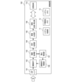
- FIG. 2 is a block diagram showing the configuration of the image sensor 102.
- the timing pulse control unit 201 controls the operation of the image sensor 102 by supplying operating clocks and timing signals to each part of the image sensor 102.
- the vertical scanning circuit 202 performs timing control for reading out a video signal from the pixel section 203.
- the pixel section 203 has multiple photoelectric conversion elements (multiple pixels) arranged two-dimensionally (for example, in a matrix).
- the photoelectric conversion elements convert light incident on the photoelectric conversion elements into a voltage (pixel signal voltage).
- the timing control performed by the vertical scanning circuit 202 is timing control for sequentially reading out pixel signal voltages from multiple photoelectric conversion elements during one frame period. In general, the pixel signal voltages are read out row by row from the top row to the bottom row of the pixel section 203.
- the column AMP (amplifier) 204 electrically amplifies the video signal read out from the pixel section 203. This increases the difference between the level of the video signal output from the column AMP 204 and the level of the noise output from the column ADC (analog-to-digital converter) 205. As a result, the signal-to-noise (SN) ratio of the video signal output from the column ADC is improved.
- the timing pulse control unit 201 can change the gain (amplification rate) of the column AMP 204.
- the column AMP 204 has two input memories and can output two video signals with different gains. By using two input memories, two video signals corresponding to the same time can be obtained as two video signals with different gains. Note that the column AMP 204 may be able to output three or more video signals corresponding to the same time.
- the column ADC 205 converts the analog signal, which is the video signal output (read out) from the column AMP 204, into a digital signal (digital data) through AD conversion.
- the horizontal transfer circuit 206 reads out the digitized video signal from the column ADC 205 and outputs the video signal to the signal processing circuit 207.
- the signal processing circuit 207 is a circuit that performs digital processing (digital signal processing), performs digital processing on the video signal output from the horizontal transfer circuit 206, and outputs the digitally processed video signal to the external output circuit 208.
- the signal processing circuit 207 can perform, as digital processing, offset processing that adds a predetermined value, and gain processing that multiplies a predetermined value. If the pixel unit 203 has a pixel area that is intentionally shaded (shaded area), the signal processing circuit 207 may perform, as digital processing, black level clamp processing using the video signal of the shaded area.
- the external output circuit 208 has a serializer function and converts the multi-bit parallel signal, which is the video signal output from the signal processing circuit 207, into a serial signal.
- the external output circuit 208 then converts the resulting serial signal into a video signal of a predetermined format (e.g., an LVDS signal) and outputs the video signal to the outside (e.g., the image acquisition unit 103 in FIG. 1).
- a predetermined format e.g., an LVDS signal
- the image acquisition unit 103 performs various processes on the video signal output from the image sensor 102. For example, if AD conversion is not performed inside the image sensor 102, the image acquisition unit 103 has an analog front end and performs AD conversion on the video signal output from the image sensor 102.
- the image acquisition unit 103 may perform various processes such as removing fixed pattern noise of the image sensor 102 and black level clamping.
- the image acquisition unit 103 may separate the video signal output from the image sensor 102 into a video signal for recording and a control signal (for example, a signal for controlling the image sensor 102). In the first embodiment, the image acquisition unit 103 outputs the video signal for recording to the signal processing unit 104 and outputs the control signal to the exposure control unit 107.
- the signal processing unit 104 performs various processes, including development, on the video signal (RAW image) output from the image acquisition unit 103.
- the image after development will be referred to as a developed image.
- the signal processing unit 104 then outputs the processed video signal (developed image) to the image synthesis unit 105.
- the signal processing unit 104 performs at least one of pixel addition, noise reduction, gamma correction, knee correction, digital gain processing, and scratch correction.
- the image acquisition unit 103 and the signal processing unit 104 have memory circuits that store setting values required for various processes.
- the image synthesis unit 105 acquires from the signal processing unit 104 a plurality of developed images (video signals of a plurality of developed images) corresponding to a plurality of (e.g., two) RAW images output from the imaging element 102, respectively, and synthesizes the plurality of developed images. This generates a synthetic image (video signal of the synthetic image) with a different gradation from the plurality of developed images.
- the image synthesis unit 105 performs image processing (HDR synthesis) to synthesize a plurality of SDR (Standard Dynamic Range) images with different brightness to obtain an HDR (High Dynamic Range) image.
- the image synthesis unit 105 then outputs the video signal of the synthetic image to the image recording/playback unit 106.
- the image recording and playback unit 106 generates a file including multiple (e.g., two) RAW images output from the image sensor 102, and records the generated file in a storage device that is an external device of the image capture device 100, or in a storage medium 110 provided in the image capture device 100.
- the image recording and playback unit 106 also stores the composite image output from the image synthesis unit 105 in a file.
- the image recording and playback unit 106 can also play back images (display images on a display unit, not shown) based on the file recorded in the storage device or storage medium 110.
- the storage medium 110 may be built into the image capture device 100, or may be detachable from the image capture device 100.
- the exposure control unit 107 calculates the optimal exposure amount based on the signal (control signal) output from the image acquisition unit 103, and outputs the calculation result to the image sensor control unit 108.
- the image sensor control unit 108 controls the image sensor 102 according to the optimal exposure output from the image sensor control unit 108.
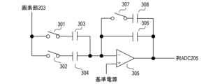
- FIG. 3 is a circuit diagram showing the configuration of a portion of column AMP 204 that corresponds to one column of pixel section 203.
- the circuit in FIG. 3 includes switches (SW) 301, SW302, capacitance (C) 303, C304, operational amplifier (OP) 305, SW307, C308, and C309.
- SW301 is an operational amplifier.
- the ratio of the input capacitance and feedback capacitance connected to OP305 becomes the gain (amplification rate) of OP305. For example, when SW301 is closed and SW302 is opened, C303 is connected to OP305 as an input capacitance, and when SW301 is opened and SW302 is closed, C304 is connected to OP305 as an input capacitance.
- FIG. 4 is a block diagram showing a configuration for compositing a plurality of developed images (e.g., HDR compositing).
- an H-developed image which is a developed image obtained with a high gain higher than the normal gain
- an L-developed image which is a developed image obtained with a low gain lower than the normal gain
- the exposure correction unit 401 is part of the signal processing unit 104, and adjusts the brightness of the H-developed image and the brightness of the L-developed image so that the brightness of the composite image increases linearly with an increase in the amount of light input to the image sensor 102 (the actual brightness of the subject).
- the image composition unit 402 is the image composition unit 105, and generates a composite image by combining the H-developed image and the L-developed image after brightness adjustment.
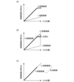
- Figures 5A to 5C are graphs in which the horizontal axis represents the amount of light input to the image sensor 102 and the vertical axis represents the brightness of the developed image.
- the thick line in FIG. 5A indicates the correspondence relationship between the amount of light input to the image sensor 102 and the brightness of the H-developed image
- the thin line in FIG. 5A indicates the correspondence relationship between the amount of light input to the image sensor 102 and the brightness of the L-developed image.
- the correspondence relationship between the H-developed image (thick line) and the correspondence relationship between the L-developed image (thin line) are significantly different. Therefore, the H-developed image and the L-developed image cannot be combined as is.
- the exposure correction unit 401 in FIG. 4 matches the brightness of the H-developed image with the brightness of the L-developed image.
- the exposure correction unit 401 applies (multiplies) a gain greater than 1 to the L-developed image to obtain an L2-developed image that matches the brightness of the H-developed image.
- the image synthesis unit 402 in FIG. 4 synthesizes the H-developed image and the L2-developed image. For example, as shown in FIG. 5C, the image synthesis unit 402 generates a synthesized image by replacing blown-out areas of the H-developed image with the L2-developed image.
- the method of generating a composite image is not limited to the above method.
- a gain smaller than 1 may be applied to the H-developed image to obtain an H2-developed image that matches the brightness of the L-developed image.
- a composite image may be generated by replacing the black crushed area of the L-developed image with the H2-developed image.
- the H2-developed image and the L-developed image may be synthesized.
- the brightness of both the H-developed image and the L-developed image may be adjusted, and the H-developed image and the L-developed image after the brightness adjustment may be synthesized.
- An appropriate-developed image which is a developed image obtained with a normal gain, may be used instead of the H-developed image or the L-developed image.
- Three or more developed images corresponding to three or more RAW images may be synthesized.
- a composite image in RAW format may be generated by synthesizing multiple RAW images, and the composite image may be subjected to development processing.
- the method is not particularly limited.
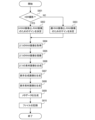
- FIG. 6 is a flowchart showing the recording process of the imaging device 100.
- the recording process in FIG. 6 is realized by the system control unit 11 expanding a program stored in the non-volatile memory 12 into the system memory 13 and executing it.
- the recording process in FIG. 6 is performed in response to a shooting instruction from the user, for example.
- step S601 the system control unit 11 determines whether or not to perform HDR shooting to obtain an HDR image as a composite image. If HDR shooting is to be performed, the process proceeds to step S602; if not (if SDR shooting is to be performed to obtain an SDR image as a composite image), the process proceeds to step S603.
- step S602 the system control unit 11 determines the gain (amplification rate, ISO sensitivity) of the image sensor 102 so that an H-RAW image and an L-RAW image can be obtained.
- the H-RAW image is a RAW image for obtaining an H-developed image
- the L-RAW image is a RAW image for obtaining an L-developed image.
- step S602 the system control unit 11 determines the gain of the image sensor 102 so that a suitable RAW image and an L-RAW image are obtained.
- the suitable RAW image is a RAW image for obtaining the suitable RAW image.
- the method of determining the gain is not limited to the above method.
- the system control unit 11 may determine the gain according to instructions from the user, or may determine the gain automatically.
- the system control unit 11 may determine the gain according to the shooting mode. For example, in a still image shooting mode, the system control unit 11 may determine the gain so that an appropriate RAW image and an L-RAW image are obtained, and in a video shooting mode, the system control unit 11 may determine the gain so that an H-RAW image and an L-RAW image are obtained.
- step S604 the system control unit 11 sets the gain determined in step S602 or step S603 in the image sensor 102, and uses the image acquisition unit 103 to acquire two RAW images with different gains (two RAW images with different brightness).
- an H-RAW image and an L-RAW image are obtained
- an appropriate-RAW image and an L-RAW image are obtained.
- the L-RAW image is a RAW image that is darker than the appropriate-RAW image
- the H-RAW image is a RAW image that is brighter than the appropriate-RAW image.
- the L-developed image is a developed image that is darker than the appropriate-developed image
- the H-developed image is a developed image that is brighter than the appropriate-developed image.
- step S605 the system control unit 11 uses the signal processing unit 104 to perform development processing on the two RAW images acquired in step S604, thereby generating two developed images. Note that in step S605, the brightness adjustment described with reference to Figures 4 and 5B is also performed.
- the developed images generated in step S605 will be referred to as material images.
- step S606 the system control unit 11 uses the image synthesis unit 105 to synthesize the two material images generated in step S605 to generate a composite image.
- step S607 the system control unit 11 uses the image recording/playback unit 106 to encode the composite image generated in step S606.
- the encoded composite image will be referred to as a display composite image (composite image for display).
- a display composite image in JPEG (Joint Photographic Experts Group) format is obtained.
- HDR shooting for example, a display composite image in HEVC (High Energy Video Coding) format is obtained.
- a display composite image in the High Resolution Video Codec (HVDC) format is obtained.
- the display composite image has a resolution equivalent to that of the RAW image or the material image.
- the system control unit 11 may generate a LTHM (Large Thumbnail) image or a THM (Thumbnail) image for simple display by encoding and resizing the composite image using the image recording/playback unit 106.
- LTHM Large Thumbnail
- THM Thumbnail
- step S608 the system control unit 11 uses the image recording and playback unit 106 to encode the two material images generated in step S605.
- the encoded material images are referred to as display material images (material images for display).
- the encoding format of the display material images may be the same as that of the display composite image, or it may be different. If the encoding format of the display material images is the same as that of the display composite image, the display composite image and the display material images can be played back using the same processing, making playback more efficient.
- step S609 the system control unit 11 uses the image recording/playback unit 106 to generate metadata for the file to be recorded on the storage medium 110.
- the system control unit 11 stores information about the two RAW images acquired in step S604 in the metadata.
- the information about the two RAW images is, for example, information that can identify whether each of the two RAW images is an H-RAW image, an L-RAW image, or a suitable RAW image. Whether a RAW image is an H-RAW image, an L-RAW image, or a suitable RAW image may be indicated by a bit definition.
- step S610 the system control unit 11 uses the image recording and playback unit 106 to generate a file (RAW image file) including the two RAW images acquired in step S604 and the metadata generated in step S609.
- the system control unit 11 uses the image recording and playback unit 106 to record the generated file in the storage medium 110.
- the system control unit 11 also stores the display composite image generated in step S607 and the two display material images generated in step S608 in a file recorded in the storage medium 110.
- the metadata is stored, for example, in a file header.
- the metadata may also be stored in a MakerNote that is uniquely defined by the developer and manufacturer of the imaging device 100.
- FIG. 7 is a schematic diagram showing the structure of a file recorded on storage medium 110.
- the file in FIG. 7 has the ISO Base Media File Format defined in ISO/IEC 14496-12. Therefore, the file in FIG. 7 has a tree structure, with each node called a box. Each box can have multiple boxes as child elements.
- File 701 starts with ftype 702, followed by moov 703, uuid 709, Etc 708, and mdat 711.
- ftype 702 is a box that stores (describes) the file type.
- moov 703 is a box that stores metadata.
- uuid 709 is a user-defined box.
- mdat 711 is a box that stores media data (image data).
- Etc 708 is a miscellaneous box.
- Moov703 has as its child elements uuid704, which is a user-defined box, and trak707, which is a box that stores information referencing ImageData712.
- uuid704 has as its child elements MetaData705, which is a box that stores metadata, and THM706, which is a box that stores image data of THM images.
- Metadata includes, for example, the date and time the file was created, the shooting conditions, information on whether the image was shot in HDR or SDR, RAW image information (suitable RAW image/H-RAW image/L-RAW image), and other shooting information.
- uuid709 has as its child element LTHM710, which is a box that stores image data for the LTHM image.
- mdat711 has as its child element ImageData712, which is a box that stores image data for the RAW image, the display source image, and the display composite image.
- the image data stored in ImageData712, THM706, and LTHM710 differs between SDR and HDR shooting.
- the file structure is not limited to the above structure.
- the file may contain boxes different from the above boxes. At least one of the display composite image and the display material image may not be included in the file.
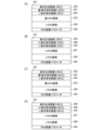
- Figure 8A is a schematic diagram showing ImageData 812 when a still image is captured in SDR.
- ImageData 812 in Figure 8A stores a suitable-RAW image 823, an L-RAW image 824, and RAW development parameters 825.
- the RAW development parameters are parameters used in the development process of a RAW image.
- ImageData 812 in Figure 8A further stores a display composite image 820, a suitable-display material image 821, and an L-display material image 822.
- Display composite image 820, suitable-display material image 821, and L-display material image 822 are SDR images in JPEG format.
- Suitable-display material image 821 is a display material image corresponding to the suitable-RAW image, and is generated by encoding the suitable-developed image.
- the L-display material image 822 is a display material image that corresponds to the L-RAW image, and is generated by encoding the L-developed image.
- FIG. 8B is a schematic diagram showing ImageData 812 when SDR video shooting is performed.
- ImageData 812 in FIG. 8B stores H-RAW image 827, L-RAW image 824, and RAW development parameters 825.
- ImageData 812 in FIG. 8B also stores display composite image 820, H-display material image 826, and L-display material image 822.
- H-display material image 826 is also an SDR image in JPEG format, like display composite image 820 and L-display material image 822.
- H-display material image 826 is a display material image corresponding to the H-RAW image, and is generated by encoding the H-developed image.
- a video file can be generated by storing multiple frames of data in one file, with ImageData 812 in FIG. 8B as one frame of data.
- FIG. 8C is a schematic diagram showing ImageData 812 when a still image is shot in HDR.
- ImageData 812 in FIG. 8C stores a suitable-RAW image 823, an L-RAW image 824, and RAW development parameters 825.
- ImageData 812 in FIG. 8C further stores a display composite image 830, a suitable-display material image 831, and an L-display material image 832.
- Display composite image 830 is an HDR image in the HEVC format
- suitable-display material image 831 and L-display material image 832 are SDR images in the HEVC format.
- Suitable-display material image 831 is a display material image corresponding to the suitable-RAW image, and is generated by encoding the suitable-developed image.
- L-display material image 832 is a display material image corresponding to the L-RAW image, and is generated by encoding the L-developed image.
- FIG. 8D is a schematic diagram showing ImageData 812 when HDR video shooting is performed.
- ImageData 812 in FIG. 8D stores H-RAW image 827, L-RAW image 824, and RAW development parameters 825.
- ImageData 812 in FIG. 8D also stores display composite image 830, H-display material image 836, and L-display material image 832.
- H-display material image 836 is also an SDR image in HEVC format, like L-display material image 832.
- H-display material image 836 is a display material image corresponding to the H-RAW image, and is generated by encoding the H-developed image.
- a video file can be generated by storing multiple frames of data in one file, with ImageData 812 in FIG. 8D as data for one frame.
- the first embodiment when multiple RAW images are stored in one file, information about the multiple RAW images is also stored in the file. This makes it easy to identify what type of RAW images the multiple RAW images contained in the file are from the information contained in the file. Note that in the first embodiment, multiple developed images (multiple display material images) corresponding to the multiple RAW images are also stored in the file. Therefore, it is easy to identify what type of RAW images the multiple RAW images contained in the file are from the multiple developed images as well.
- Second Embodiment A second embodiment of the present invention will be described below. Note that, in the following, a description of the same points as in the first embodiment (for example, the same configuration and processing as in the first embodiment) will be omitted, and only points different from the first embodiment will be described.
- FIG. 9 is a flowchart showing the playback process of the imaging device 100.
- the playback process in FIG. 9 is realized by the system control unit 11 expanding a program stored in the non-volatile memory 12 into the system memory 13 and executing it.
- the playback process in FIG. 9 is performed in response to a playback instruction from a user, for example.
- the file containing multiple RAW images is a file containing an appropriate RAW image and an L-RAW image.
- step S901 the system control unit 11 uses the image recording/playback unit 106 to read a file (RAW image file) from the storage medium 110 and determines whether the file contains multiple RAW images. Whether the file contains multiple RAW images can be determined based on information included in the file (e.g., MetaData 705 in FIG. 7). If the file contains multiple RAW images, the process proceeds to step S902; if not (if the file contains only one RAW image), the process proceeds to step S903.
- a file RAW image file
- step S902 the system control unit 11 uses the image recording and playback unit 106 to play (display) the display composite image.
- the display composite image may be included in the file, or may be generated at the timing of step S902. Since a file containing multiple RAW images is likely to be a file intended for playing a composite image, the display composite image is played first. As will be described in detail later, multiple images including the display composite image and multiple display material images can be played.
- step S903 the system control unit 11 uses the image recording/playback unit 106 to play back (display) a display developed image (developed image for display) generated by performing a development process on the RAW image included in the file.
- the display developed image may be included in the file, or may be generated at the timing of step S903.
- step S904 the system control unit 11 determines whether a file forwarding operation (a user operation for switching the file for which images are to be played back) has been performed. If a file forwarding operation has been performed, the process proceeds to step S905; if not, the process proceeds to step S906.
- a file forwarding operation a user operation for switching the file for which images are to be played back
- step S905 the system control unit 11 switches the file from which images are to be played to another file. Then, the process proceeds to step S901.
- the display material image of the switched file may be played back in step S802.
- a display material image corresponding to the same gain as the display material image played back before the file was switched may be played back. For example, if an L-display material image was being played back before the file was switched, the L-display material image of the switched file may be played back. This allows the user to efficiently check images of the same type.
- step S802 in the case of continuous shooting, the display material image of the file after switching may be played, and in the case of single shooting, the display composite image of the file after switching may be played.
- step S906 the system control unit 11 determines whether an image forwarding operation (a user operation for switching the image being played back without switching the file) has been performed. If an image forwarding operation has been performed, the process proceeds to step S907; if not, the process proceeds to step S904.
- an image forwarding operation a user operation for switching the image being played back without switching the file
- step S907 the system control unit 11 uses the image recording and playback unit 106 to play (display) the suitable-display material image.
- the suitable-display material image may be included in a file, or may be generated at the timing of step S907.
- step S908 the system control unit 11 determines whether or not a file transfer operation has been performed. If a file transfer operation has been performed, the process proceeds to step S905; if not, the process proceeds to step S909.
- step S909 the system control unit 11 determines whether an image forwarding operation has been performed. If an image forwarding operation has been performed, the process proceeds to step S910; if not, the process proceeds to step S904.
- step S910 the system control unit 11 uses the image recording and playback unit 106 to play (display) the L-display material image.
- the L-display material image may be included in a file, or may be generated at the timing of step S910.
- step S911 it is determined whether a file forwarding operation has been performed. If a file forwarding operation has been performed, the process proceeds to step S905; if not, the playback process in FIG. 9 ends.
- the system control unit 11 uses the image recording and playback unit 106 to play (display) the display composite image.
- the image to be played is switched between multiple images including the display composite image and multiple display material images in response to the image advance operation.
- the second embodiment it is possible to play back (display) a plurality of developed images (a plurality of display material images) each corresponding to a plurality of RAW images contained in a file. This allows the user to easily identify what type of RAW images the plurality of RAW images contained in a file are.
- the playback process may also be performed by a device (electronic device) separate from the imaging device 100.
- a device electronic device
- information on the multiple RAW images for example, multiple icons each representing the multiple RAW images
- a file contains multiple RAW images multiple developed images corresponding to the multiple RAW images may be displayed side by side in response to a specific user operation.
- an appropriate-display material image and an L-display material image may be displayed side by side.
- a composite image and multiple developed images corresponding to the multiple RAW images may be displayed side by side in response to a specific user operation.
- a display composite image, an appropriate-display material image, and an L-display material image may be displayed side by side in the left-right direction.
- FIG. 10 is a flowchart showing the playback process of the imaging device 100.
- the playback process in FIG. 10 is realized by the system control unit 11 expanding a program stored in the non-volatile memory 12 into the system memory 13 and executing it.
- the playback process in FIG. 10 is performed in response to a playback instruction from a user, for example.
- the file containing multiple RAW images is a file containing an appropriate RAW image and an L-RAW image.
- step S1001 similar to step S901 in FIG. 9, the system control unit 11 uses the image recording/playback unit 106 to read a file (RAW image file) from the storage medium 110 and determines whether the file contains multiple RAW images. If the file contains multiple RAW images, the process proceeds to step S1002, and if not (if the file contains only one RAW image), the process proceeds to step S1003.
- a file RAW image file
- step S1002 similar to step S902, the system control unit 11 uses the image recording and playback unit 106 to play (display) the composite image.
- step S1003 similar to step S903, the system control unit 11 uses the image recording and playback unit 106 to play back (display) the displayed developed image.
- step S1004 the system control unit 11 determines whether a redevelopment operation (a user operation for performing development processing (redevelopment processing) using newly specified RAW development parameters by the user) has been performed. If a redevelopment operation has been performed, the process proceeds to step S1011; if not, the process proceeds to step S1005.
- a redevelopment operation a user operation for performing development processing (redevelopment processing) using newly specified RAW development parameters by the user
- step S1005 similar to step S906, the system control unit 11 determines whether or not an image forwarding operation has been performed. If an image forwarding operation has been performed, the process proceeds to step S1006; if not, the process proceeds to step S1004.
- step S1006 similar to step S907, the system control unit 11 uses the image recording and playback unit 106 to play (display) the appropriate display material image.
- step S1007 the system control unit 11 determines whether or not a redevelopment operation has been performed. If a redevelopment operation has been performed, the process proceeds to step S1011; if not, the process proceeds to step S1008.
- step S1008 similar to step S909, the system control unit 11 determines whether or not an image forwarding operation has been performed. If an image forwarding operation has been performed, the process proceeds to step S1009; if not, the process proceeds to step S1004.
- step S1009 similar to step S910, the system control unit 11 uses the image recording and playback unit 106 to play (display) the L-display material image.
- step S1010 the system control unit 11 determines whether or not a redevelopment operation has been performed. If a redevelopment operation has been performed, the process proceeds to step S1011; if not, the playback process in FIG. 10 ends.
- step S1011 the system control unit 11 performs redevelopment processing of the RAW image using the newly specified RAW development parameters.
- the redevelopment processing is performed using the signal processing unit 104. For example, if a redevelopment operation is performed while a display composite image is being played back, redevelopment processing of multiple RAW images (for example, redevelopment processing of a suitable-RAW image and an L-RAW image) is performed. If a redevelopment operation is performed while a display material image is being played back, redevelopment processing of a RAW image corresponding to the display material image is performed. For example, if a redevelopment operation is performed while a suitable-display material image is being played back, redevelopment processing of the suitable-RAW image is performed. If a redevelopment operation is performed while an L-display material image is being played back, redevelopment processing of the L-RAW image is performed. If a file contains only one RAW image, redevelopment processing of that one RAW image is performed.
- step S1012 the system control unit 11 determines whether or not redevelopment processing has been performed on multiple RAW images in step S1011. If redevelopment processing has been performed on multiple RAW images, the process proceeds to step S1013; if not (if redevelopment processing has been performed on one RAW image), the process proceeds to step S1014.
- step S1013 similar to step S606 in FIG. 6, the system control unit 11 uses the image synthesis unit 105 to synthesize the multiple developed images (multiple material images) generated in step S1011 to generate a composite image.
- step S1014 similar to steps S607 and S608 in FIG. 6, the system control unit 11 encodes the image using the image recording and playback unit 106.
- the encoded image is hereafter referred to as the redeveloped image. If multiple RAW images have been redeveloped, the composite image generated in step S1013 is encoded; otherwise (if one RAW image has been redeveloped), the developed image generated in step S1011 is encoded.
- the system control unit 11 then updates the image to be played back to the redeveloped image using the image recording and playback unit 106.
- step S1015 the system control unit 11 uses the image recording and playback unit 106 to update the metadata of the file. For example, the system control unit 11 adds information about the redevelopment process (for example, the date and time when the redevelopment process was performed) to the metadata.
- the system control unit 11 adds information about the redevelopment process (for example, the date and time when the redevelopment process was performed) to the metadata.
- step S1016 the system control unit 11 uses the image recording/playback unit 106 to store the redeveloped image (and the RAW development parameters corresponding to the redeveloped image) in a file.
- the redeveloped image may be added to the file, or the image stored in the file may be replaced with the redeveloped image.
- the display composite image stored in the file may be replaced with the redeveloped image.
- the suitable display material image stored in the file may be replaced with the redeveloped image.
- the L-RAW image has been redeveloped, the L-display material image stored in the file may be replaced with the redeveloped image.
- the image the user needs can be obtained through redevelopment processing.
- the various controls described above as being performed by the system control unit 11 may be performed by at least one piece of hardware (e.g., at least one processor and/or at least one circuit).
- One piece of hardware may control the entire device, or multiple pieces of hardware may share the processing to control the entire device.
- the present invention has been described as being applied to an imaging device (digital camera), but it is not limited to imaging devices and can be applied to any information processing device (electronic device) capable of acquiring RAW images.
- the present invention can be applied to personal computers, PDAs, mobile phone terminals, portable image viewers, printer devices, digital photo frames, music players, game consoles, and e-book readers.
- the present invention can also be applied to video players, display devices (including projection devices), tablet terminals, smartphones, AI speakers, home appliances, and in-vehicle devices.
- the present invention can also be realized by a process in which a program for implementing one or more of the functions of the above-described embodiments is supplied to a system or device via a network or a storage medium, and one or more processors in a computer of the system or device read and execute the program.
- the present invention can also be realized by a circuit (e.g., ASIC) that implements one or more of the functions.
- the disclosure of the present embodiment includes the following configuration, method, program, and medium.
- Configuration 2 2.
- the image forming apparatus further includes a developing unit for generating a plurality of developed images by subjecting the plurality of RAW images to a development process, 3.
- the information processing apparatus according to configuration 1 or 2, wherein the recording means generates the file including the plurality of RAW images, information about the plurality of RAW images, and the plurality of developed images.
- Configuration 4 a synthesizing unit for synthesizing the plurality of raw images or the plurality of developed images to generate a synthetic image having a different gradation from the plurality of developed images; 4.
- the information processing apparatus according to configuration 3, wherein the recording means generates the file including the plurality of RAW images, information about the plurality of RAW images, and the composite image.
- the plurality of developed images are SDR images; 5.
- the information processing device according to configuration 4, wherein the composite image is an HDR image.
- the recording means stores, as the file,
- the information processing device according to any one of configurations 1 to 5, characterized in that it generates a first RAW image, a second RAW image darker than the first RAW image, and a file containing information on the first RAW image and the second RAW image, or a file containing information on the second RAW image, a third RAW image brighter than the first RAW image, and the second RAW image and the third RAW image.
- the apparatus further includes a playback means for playing back an image based on the file recorded on the storage medium,
- the regeneration means includes: determining whether a file to be reproduced contains a plurality of RAW images based on information contained in the file; If the target file contains multiple RAW images, first: (1) a composite image generated by combining a plurality of RAW images included in the target file, the composite image having a different gradation from the plurality of RAW images; (2) Reproducing any one of a plurality of images including a plurality of developed images generated by performing a development process on a plurality of RAW images included in the target file; 7.
- the regeneration means includes: in response to a second user operation, switching the target file to another file;
- Configuration 10 The information processing device according to any one of configurations 7 to 9, wherein the reproduction means updates the image to be reproduced to an image generated using newly specified development parameters in response to a third user operation.
- (Configuration 11) The information processing device described in configuration 10, characterized in that the reproduction means updates the image to be reproduced to a new composite image generated using the newly specified development parameters in response to the third user operation while the composite image is being reproduced.
- (Configuration 12) The information processing device described in configuration 10 or 11, characterized in that the reproduction means updates the image to be reproduced to a new developed image generated using the newly specified development parameters in response to the third user operation while the developed image is being reproduced.
- (Configuration 13) The information processing device according to any one of configurations 7 to 12, wherein the playback means controls the display of information about the multiple RAW images when the target file contains multiple RAW images.
- (Configuration 14) The information processing device according to any one of configurations 7 to 13, characterized in that, when the target file contains multiple RAW images, the playback means controls the display of the multiple developed images side by side in response to a fourth user operation.
- (Configuration 15) The information processing device of any one of configurations 7 to 13, characterized in that, when the target file contains multiple RAW images, the playback means controls to display the composite image and the multiple developed images side by side in response to a fourth user operation.
- (Configuration 16) a playback means for playing back an image based on a file recorded on a storage medium;
- the regeneration means includes: If the file you want to play contains multiple RAW images, first (1) a composite image generated by combining a plurality of RAW images included in the target file, the composite image having a different gradation from the plurality of RAW images; (2) Reproducing any one of a plurality of images including a plurality of developed images generated by performing a development process on a plurality of RAW images included in the target file; An information processing apparatus which switches an image to be reproduced among the plurality of images in response to a predetermined user operation.
- Method 1 acquiring a plurality of RAW images having different brightness levels; an information processing method comprising the steps of: generating one file including the plurality of RAW images and information about the plurality of RAW images; and recording the file on a storage medium.
- Method 2 reproducing an image based on the file recorded on the storage medium; and switching the image to be reproduced, If the file you want to play contains multiple RAW images, first (1) a composite image generated by combining a plurality of RAW images included in the target file, the composite image having a different gradation from the plurality of RAW images; (2) Any one of a plurality of images including a plurality of developed images generated by performing a development process on a plurality of RAW images included in the target file is reproduced; An information processing method, comprising the steps of: switching an image to be reproduced among the plurality of images in response to a predetermined user operation.
- program A program for causing a computer to function as each of the means of the information processing device according to any one of configurations 1 to 16.
- Medium A computer-readable storage medium storing a program for causing a computer to function as each of the means of the information processing device according to any one of configurations 1 to 16.
- Imaging device 11 System control unit 103: Image acquisition unit 106: Image recording/playback unit
Landscapes
- Engineering & Computer Science (AREA)
- Physics & Mathematics (AREA)
- General Physics & Mathematics (AREA)
- Theoretical Computer Science (AREA)
- Multimedia (AREA)
- Signal Processing (AREA)
- Studio Devices (AREA)
Priority Applications (2)
| Application Number | Priority Date | Filing Date | Title |
|---|---|---|---|
| CN202380092823.9A CN120752924A (zh) | 2023-02-03 | 2023-11-07 | 信息处理装置和信息处理方法 |
| US19/272,638 US20250342566A1 (en) | 2023-02-03 | 2025-07-17 | Information processing device and information processing method |
Applications Claiming Priority (2)
| Application Number | Priority Date | Filing Date | Title |
|---|---|---|---|
| JP2023-015306 | 2023-02-03 | ||
| JP2023015306A JP2024110616A (ja) | 2023-02-03 | 2023-02-03 | 情報処理装置および情報処理方法 |
Related Child Applications (1)
| Application Number | Title | Priority Date | Filing Date |
|---|---|---|---|
| US19/272,638 Continuation US20250342566A1 (en) | 2023-02-03 | 2025-07-17 | Information processing device and information processing method |
Publications (1)
| Publication Number | Publication Date |
|---|---|
| WO2024161742A1 true WO2024161742A1 (ja) | 2024-08-08 |
Family
ID=92146114
Family Applications (1)
| Application Number | Title | Priority Date | Filing Date |
|---|---|---|---|
| PCT/JP2023/040091 Ceased WO2024161742A1 (ja) | 2023-02-03 | 2023-11-07 | 情報処理装置および情報処理方法 |
Country Status (4)
| Country | Link |
|---|---|
| US (1) | US20250342566A1 (https=) |
| JP (1) | JP2024110616A (https=) |
| CN (1) | CN120752924A (https=) |
| WO (1) | WO2024161742A1 (https=) |
Families Citing this family (1)
| Publication number | Priority date | Publication date | Assignee | Title |
|---|---|---|---|---|
| JP2025012556A (ja) * | 2023-07-13 | 2025-01-24 | キヤノン株式会社 | 撮影制御装置、撮像装置、撮影制御方法、及びプログラム |
Citations (4)
| Publication number | Priority date | Publication date | Assignee | Title |
|---|---|---|---|---|
| JP2005323162A (ja) * | 2004-05-10 | 2005-11-17 | Fuji Photo Film Co Ltd | 撮像装置及び画像記録方法 |
| JP2020141297A (ja) * | 2019-02-28 | 2020-09-03 | キヤノン株式会社 | 撮像装置及びその制御方法及びプログラム |
| JP2020141335A (ja) * | 2019-02-28 | 2020-09-03 | キヤノン株式会社 | 撮像装置、画像処理装置、それらの制御方法、プログラム |
| JP2022117079A (ja) * | 2021-01-29 | 2022-08-10 | キヤノン株式会社 | 画像処理装置、画像処理方法及びプログラム |
-
2023
- 2023-02-03 JP JP2023015306A patent/JP2024110616A/ja active Pending
- 2023-11-07 WO PCT/JP2023/040091 patent/WO2024161742A1/ja not_active Ceased
- 2023-11-07 CN CN202380092823.9A patent/CN120752924A/zh active Pending
-
2025
- 2025-07-17 US US19/272,638 patent/US20250342566A1/en active Pending
Patent Citations (4)
| Publication number | Priority date | Publication date | Assignee | Title |
|---|---|---|---|---|
| JP2005323162A (ja) * | 2004-05-10 | 2005-11-17 | Fuji Photo Film Co Ltd | 撮像装置及び画像記録方法 |
| JP2020141297A (ja) * | 2019-02-28 | 2020-09-03 | キヤノン株式会社 | 撮像装置及びその制御方法及びプログラム |
| JP2020141335A (ja) * | 2019-02-28 | 2020-09-03 | キヤノン株式会社 | 撮像装置、画像処理装置、それらの制御方法、プログラム |
| JP2022117079A (ja) * | 2021-01-29 | 2022-08-10 | キヤノン株式会社 | 画像処理装置、画像処理方法及びプログラム |
Also Published As
| Publication number | Publication date |
|---|---|
| US20250342566A1 (en) | 2025-11-06 |
| CN120752924A (zh) | 2025-10-03 |
| JP2024110616A (ja) | 2024-08-16 |
Similar Documents
| Publication | Publication Date | Title |
|---|---|---|
| CN107836114B (zh) | 数据记录设备及其控制方法、摄像设备和计算机可读存储介质 | |
| US20090284618A1 (en) | Image processing device and method, and computer-readable recording medium containing program | |
| JP6603558B2 (ja) | 撮像素子および撮像装置 | |
| JP6624889B2 (ja) | 映像処理装置、映像処理方法、及び映像処理プログラム | |
| JP4992860B2 (ja) | 撮像装置及びプログラム | |
| JP6549409B2 (ja) | 撮像装置、撮像方法、およびプログラム | |
| JP2020012879A (ja) | 撮像素子、焦点検出装置、撮像方法、および焦点検出方法 | |
| US20250342566A1 (en) | Information processing device and information processing method | |
| JP2020136823A (ja) | 画像処理装置、撮像装置、画像処理方法、撮像装置の制御方法、及びプログラム | |
| JP4560422B2 (ja) | 撮像装置及びその制御方法 | |
| JP6049425B2 (ja) | 撮像装置、画像処理装置、及び制御方法 | |
| JP2011233985A (ja) | 画像処理装置及びその制御方法 | |
| JP6075829B2 (ja) | 撮像装置、カメラシステム、撮像装置の制御方法、プログラム、記憶媒体 | |
| US7256832B2 (en) | CCD camera forming a still image by adding offset values to the odd and even fields and method for controlling the same | |
| JP4220406B2 (ja) | 固体撮像装置およびその画像記録方法、ならびにその画像再生方法 | |
| JP2020136892A (ja) | 撮像装置、画像処理装置、制御方法、画像処理方法、及びプログラム | |
| JP4635076B2 (ja) | 固体撮像装置 | |
| US7394493B2 (en) | CCD camera utilizing an IRIS and method for controlling the same | |
| JP5470164B2 (ja) | 撮像装置 | |
| JP5169540B2 (ja) | 撮像装置および撮像方法 | |
| JP4065057B2 (ja) | 電子カメラ | |
| JP3919083B2 (ja) | 撮像装置 | |
| JP3899706B2 (ja) | 電子スチルカメラの制御方法及び電子スチルカメラ | |
| JP5057135B2 (ja) | 再生装置および再生方法、記録装置および記録方法、並びにプログラム | |
| JP2020141189A (ja) | 撮像装置およびその制御方法 |
Legal Events
| Date | Code | Title | Description |
|---|---|---|---|
| 121 | Ep: the epo has been informed by wipo that ep was designated in this application |
Ref document number: 23919877 Country of ref document: EP Kind code of ref document: A1 |
|
| WWE | Wipo information: entry into national phase |
Ref document number: 202380092823.9 Country of ref document: CN |
|
| NENP | Non-entry into the national phase |
Ref country code: DE |
|
| WWP | Wipo information: published in national office |
Ref document number: 202380092823.9 Country of ref document: CN |
|
| 122 | Ep: pct application non-entry in european phase |
Ref document number: 23919877 Country of ref document: EP Kind code of ref document: A1 |