WO2024157738A1 - 電源システム - Google Patents
電源システム Download PDFInfo
- Publication number
- WO2024157738A1 WO2024157738A1 PCT/JP2023/047179 JP2023047179W WO2024157738A1 WO 2024157738 A1 WO2024157738 A1 WO 2024157738A1 JP 2023047179 W JP2023047179 W JP 2023047179W WO 2024157738 A1 WO2024157738 A1 WO 2024157738A1
- Authority
- WO
- WIPO (PCT)
- Prior art keywords
- power supply
- power
- control unit
- voltage
- arm switch
- Prior art date
- Legal status (The legal status is an assumption and is not a legal conclusion. Google has not performed a legal analysis and makes no representation as to the accuracy of the status listed.)
- Ceased
Links
Images


Classifications
-
- H—ELECTRICITY
- H02—GENERATION; CONVERSION OR DISTRIBUTION OF ELECTRIC POWER
- H02J—ELECTRIC POWER NETWORKS; CIRCUIT ARRANGEMENTS OR SYSTEMS FOR SUPPLYING OR DISTRIBUTING ELECTRIC POWER; SYSTEMS FOR STORING ELECTRIC ENERGY
- H02J7/00—Circuit arrangements for charging or discharging batteries or for supplying loads from batteries
- H02J7/60—Circuit arrangements for charging or discharging batteries or for supplying loads from batteries including safety or protection arrangements
-
- B—PERFORMING OPERATIONS; TRANSPORTING
- B60—VEHICLES IN GENERAL
- B60L—PROPULSION OF ELECTRICALLY-PROPELLED VEHICLES; SUPPLYING ELECTRIC POWER FOR AUXILIARY EQUIPMENT OF ELECTRICALLY-PROPELLED VEHICLES; ELECTRODYNAMIC BRAKE SYSTEMS FOR VEHICLES IN GENERAL; MAGNETIC SUSPENSION OR LEVITATION FOR VEHICLES; MONITORING OPERATING VARIABLES OF ELECTRICALLY-PROPELLED VEHICLES; ELECTRIC SAFETY DEVICES FOR ELECTRICALLY-PROPELLED VEHICLES
- B60L3/00—Electric devices on electrically-propelled vehicles for safety purposes; Monitoring operating variables, e.g. speed, deceleration or energy consumption
-
- B—PERFORMING OPERATIONS; TRANSPORTING
- B60—VEHICLES IN GENERAL
- B60L—PROPULSION OF ELECTRICALLY-PROPELLED VEHICLES; SUPPLYING ELECTRIC POWER FOR AUXILIARY EQUIPMENT OF ELECTRICALLY-PROPELLED VEHICLES; ELECTRODYNAMIC BRAKE SYSTEMS FOR VEHICLES IN GENERAL; MAGNETIC SUSPENSION OR LEVITATION FOR VEHICLES; MONITORING OPERATING VARIABLES OF ELECTRICALLY-PROPELLED VEHICLES; ELECTRIC SAFETY DEVICES FOR ELECTRICALLY-PROPELLED VEHICLES
- B60L50/00—Electric propulsion with power supplied within the vehicle
- B60L50/50—Electric propulsion with power supplied within the vehicle using propulsion power supplied by batteries or fuel cells
- B60L50/60—Electric propulsion with power supplied within the vehicle using propulsion power supplied by batteries or fuel cells using power supplied by batteries
-
- B—PERFORMING OPERATIONS; TRANSPORTING
- B60—VEHICLES IN GENERAL
- B60L—PROPULSION OF ELECTRICALLY-PROPELLED VEHICLES; SUPPLYING ELECTRIC POWER FOR AUXILIARY EQUIPMENT OF ELECTRICALLY-PROPELLED VEHICLES; ELECTRODYNAMIC BRAKE SYSTEMS FOR VEHICLES IN GENERAL; MAGNETIC SUSPENSION OR LEVITATION FOR VEHICLES; MONITORING OPERATING VARIABLES OF ELECTRICALLY-PROPELLED VEHICLES; ELECTRIC SAFETY DEVICES FOR ELECTRICALLY-PROPELLED VEHICLES
- B60L58/00—Methods or circuit arrangements for monitoring or controlling batteries or fuel cells, specially adapted for electric vehicles
- B60L58/10—Methods or circuit arrangements for monitoring or controlling batteries or fuel cells, specially adapted for electric vehicles for monitoring or controlling batteries
-
- B—PERFORMING OPERATIONS; TRANSPORTING
- B60—VEHICLES IN GENERAL
- B60L—PROPULSION OF ELECTRICALLY-PROPELLED VEHICLES; SUPPLYING ELECTRIC POWER FOR AUXILIARY EQUIPMENT OF ELECTRICALLY-PROPELLED VEHICLES; ELECTRODYNAMIC BRAKE SYSTEMS FOR VEHICLES IN GENERAL; MAGNETIC SUSPENSION OR LEVITATION FOR VEHICLES; MONITORING OPERATING VARIABLES OF ELECTRICALLY-PROPELLED VEHICLES; ELECTRIC SAFETY DEVICES FOR ELECTRICALLY-PROPELLED VEHICLES
- B60L9/00—Electric propulsion with power supply external to the vehicle
- B60L9/16—Electric propulsion with power supply external to the vehicle using AC induction motors
- B60L9/18—Electric propulsion with power supply external to the vehicle using AC induction motors fed from DC supply lines
-
- H—ELECTRICITY
- H02—GENERATION; CONVERSION OR DISTRIBUTION OF ELECTRIC POWER
- H02J—ELECTRIC POWER NETWORKS; CIRCUIT ARRANGEMENTS OR SYSTEMS FOR SUPPLYING OR DISTRIBUTING ELECTRIC POWER; SYSTEMS FOR STORING ELECTRIC ENERGY
- H02J7/00—Circuit arrangements for charging or discharging batteries or for supplying loads from batteries
- H02J7/02—Circuit arrangements for charging or discharging batteries or for supplying loads from batteries for charging batteries from AC mains by converters
- H02J7/04—Regulation of charging current or voltage
- H02J7/06—Regulation of charging current or voltage using discharge tubes or semiconductor devices
-
- H—ELECTRICITY
- H02—GENERATION; CONVERSION OR DISTRIBUTION OF ELECTRIC POWER
- H02J—ELECTRIC POWER NETWORKS; CIRCUIT ARRANGEMENTS OR SYSTEMS FOR SUPPLYING OR DISTRIBUTING ELECTRIC POWER; SYSTEMS FOR STORING ELECTRIC ENERGY
- H02J7/00—Circuit arrangements for charging or discharging batteries or for supplying loads from batteries
- H02J7/14—Circuit arrangements for charging or discharging batteries or for supplying loads from batteries for charging batteries from dynamo-electric generators driven at varying speed, e.g. on vehicle
- H02J7/1469—Regulation of the charging current or voltage otherwise than by variation of field
- H02J7/1492—Regulation of the charging current or voltage otherwise than by variation of field by means of controlling devices between the generator output and the battery
-
- H—ELECTRICITY
- H02—GENERATION; CONVERSION OR DISTRIBUTION OF ELECTRIC POWER
- H02M—APPARATUS FOR CONVERSION BETWEEN AC AND AC, BETWEEN AC AND DC, OR BETWEEN DC AND DC, AND FOR USE WITH MAINS OR SIMILAR POWER SUPPLY SYSTEMS; CONVERSION OF DC OR AC INPUT POWER INTO SURGE OUTPUT POWER; CONTROL OR REGULATION THEREOF
- H02M7/00—Conversion of AC power input into DC power output; Conversion of DC power input into AC power output
- H02M7/42—Conversion of DC power input into AC power output without possibility of reversal
- H02M7/44—Conversion of DC power input into AC power output without possibility of reversal by static converters
- H02M7/48—Conversion of DC power input into AC power output without possibility of reversal by static converters using discharge tubes with control electrode or semiconductor devices with control electrode
-
- H—ELECTRICITY
- H02—GENERATION; CONVERSION OR DISTRIBUTION OF ELECTRIC POWER
- H02P—CONTROL OR REGULATION OF ELECTRIC MOTORS, ELECTRIC GENERATORS OR DYNAMO-ELECTRIC CONVERTERS; CONTROLLING TRANSFORMERS, REACTORS OR CHOKE COILS
- H02P27/00—Arrangements or methods for the control of AC motors characterised by the kind of supply voltage
- H02P27/04—Arrangements or methods for the control of AC motors characterised by the kind of supply voltage using variable-frequency supply voltage, e.g. inverter or converter supply voltage
- H02P27/06—Arrangements or methods for the control of AC motors characterised by the kind of supply voltage using variable-frequency supply voltage, e.g. inverter or converter supply voltage using DC to AC converters or inverters
-
- H—ELECTRICITY
- H02—GENERATION; CONVERSION OR DISTRIBUTION OF ELECTRIC POWER
- H02J—ELECTRIC POWER NETWORKS; CIRCUIT ARRANGEMENTS OR SYSTEMS FOR SUPPLYING OR DISTRIBUTING ELECTRIC POWER; SYSTEMS FOR STORING ELECTRIC ENERGY
- H02J2207/00—Details of circuit arrangements for charging or discharging batteries or supplying loads from batteries
- H02J2207/20—Charging or discharging characterised by the power electronics converter
Definitions
- This disclosure relates to a power supply system.
- the voltage of the external power source may be applied to the load drive device as well as the storage device.
- parasitic capacitance may occur in the load drive device, which may cause the load drive device to operate unintentionally.
- a switching element that cuts off the flow of current to the load drive device during external charging may be controlled to the off state.
- a power supply is required to supply power to operate the switching element during external charging. If this power supply is configured as a switching power supply, noise will be generated from the switching power supply during external charging. It is preferable to reduce such noise during external charging.
- the switching power supply is operated intermittently during external charging to reduce noise. It is also possible to reduce noise by lowering the output voltage of the switching power supply, for example.
- a rotating electric machine and an inverter are generally used in the power unit.
- the back electromotive force generated in the coil by the magnetic flux of the permanent magnet of the rotating electric machine can become larger than the voltage of the storage battery.
- the inverter drive power supply for driving the inverter fails due to an accident or the like, the inverter cannot be operated, all phases are shut down, and a back electromotive force is generated.
- a high-voltage back electromotive force can be applied from the coil to the storage battery or the electrical load via the diodes connected in parallel to the upper and lower arm switches.
- the high-voltage back electromotive force can cause problems such as the failure of the storage battery, etc.
- the back electromotive force can also generate unintended torque to the drive wheels.
- ASC Active Short Circuit
- short circuit control also known as short circuit control
- ASC control is a control that turns on one of the upper and lower arm switches of all phases that make up the inverter, and turns off the other. This makes it possible to prevent various problems caused by back electromotive force.
- the switching element that cuts off the current to the load drive device during external charging constitutes an inverter, and the switching power supply corresponds to the inverter drive power supply.
- the present disclosure has been made to solve the above problems, and its main objective is to provide a power supply system that is configured to be able to perform short circuit control and that allows charging from an external power source.
- a power supply system for solving the above problems includes: A power supply system capable of performing external charging in which an electric storage device is charged by an external power supply provided externally, a rotating electric machine having an armature winding; an inverter including a series connection of upper arm switches and lower arm switches, the inverter performing power conversion between the power storage device and the rotating electric machine; A drive control unit that drives and controls the upper arm switch and the lower arm switch; A first power source that supplies power to the drive control unit; a second power source that supplies power to the drive control unit when short-circuit control is performed to turn on one of the upper arm switch and the lower arm switch and turn off the other arm switch, The first power source is configured to supply power at a voltage higher than a first threshold in a normal state, and to supply power intermittently, supply power at a reduced voltage, or stop supplying power during external charging; The drive control unit is configured to perform the short-circuit control using power supplied from the second power source when the first power source fails, and to drive and control the upper arm switch and the lower arm switch using power
- the drive control unit can suppress the effects of back electromotive force by implementing short circuit control.
- the short circuit control is implemented using power from the second power source, ensuring that the short circuit control is implemented reliably.
- the first power supply is operated intermittently.
- the power supplied from the first power supply cannot stably drive and control the upper arm switch and the lower arm switch. Therefore, it is configured so that power can also be supplied from the second power supply used in short circuit control during external charging. This allows drive control to be performed reliably during external charging.
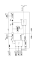
- FIG. 1 is a configuration diagram of a power supply system
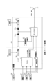
- FIG. 2 is a configuration diagram of a control device
- FIG. 3 is a flowchart showing a control flow during external charging.
- FIG. 4 is a flow chart showing the flow of abnormality diagnosis.
- FIG. 5 is a configuration diagram of a control device in a modified example
- FIG. 6 is a configuration diagram of a control device in a modified example
- FIG. 7 is a configuration diagram of a control device in a modified example.
- the power supply system 10 includes a motor 20 as a rotating electric machine, an inverter 30 as a power converter that supplies a three-phase current to the motor 20, a battery pack 40 as a charging device that can be charged and discharged, and a control device 50 that controls the inverter 30.
- the motor 20 (motor generator) is an in-vehicle main engine that is capable of transmitting power to drive wheels (not shown).
- a three-phase permanent magnet synchronous motor is used as the motor 20.
- the inverter 30 is configured with a full bridge circuit with the same number of upper and lower arms as the number of phases of the phase windings, and the current flowing through each phase winding is adjusted by turning on and off the switches provided in each arm.
- the inverter 30 has three phases of series-connected upper arm switches SWH and lower arm switches SWL.
- a first end of the armature winding 21 of the motor 20 is connected to the connection point between the upper arm switch SWH and the lower arm switch SWL.
- a second end of the armature winding 21 of each phase is connected at the neutral point.
- the armature windings 21 of each phase are arranged to be shifted from each other by 120° in electrical angle.
- voltage-controlled semiconductor switching elements are used as the upper arm switch SWH and the lower arm switch SWL, and more specifically, IGBTs (Insulated Gate Bipolar Transistors) are used.
- an upper arm diode DH which is a freewheel diode
- a lower arm diode DL which is a freewheel diode
- the positive terminal of the battery pack 40 is connected to the collector, which is the high potential terminal of each upper arm switch SWH, via a high potential electrical path 31H.
- the negative terminal of the battery pack 40 is connected to the emitter, which is the low potential terminal of each lower arm switch SWL, via a low potential electrical path 31L.
- the high-potential side electrical path 31H and the low-potential side electrical path 31L are each provided with a relay switch SMR (system main relay switch), which is configured to be able to switch between energizing and de-energizing.
- Each relay switch SMR may be driven by the control device 50, or may be driven by the upper ECU 100, which is a higher-level control device relative to the control device 50.
- the inverter 30 is equipped with a smoothing capacitor 32.
- One end of the smoothing capacitor 32 is connected to the high-potential side electrical path 31H between the relay switch SMR and the inverter 30.
- the other end of the smoothing capacitor 32 is connected to the low-potential side electrical path 31L between the relay switch SMR and the inverter 30.
- the smoothing capacitor 32 is provided between the high-potential side electrical path 31H and the low-potential side electrical path 31L so as to be in parallel with the series connection of the upper arm switch SWH and the lower arm switch SWL of each phase.
- the smoothing capacitor 32 may be provided inside or outside the inverter 30.
- the battery pack 40 is electrically connected to the motor 20 via the inverter 30.
- the battery pack 40 has a terminal voltage of, for example, 100 V or more, and is composed of multiple battery cells 41 connected in series.
- a lithium iron phosphate battery (LFP battery), a lithium ion battery, or a nickel-metal hydride battery can be used as the battery cells 41 (secondary batteries).
- Each battery cell 41 is a battery that has an electrolyte (a solution consisting of an electrolyte and a solvent) and multiple electrodes.
- the power supply system 10 also includes an external charging mechanism 60.
- the external charging mechanism 60 includes an inlet 62 and a relay 61.
- the inlet 62 is connected to the electrical paths 31H, 31L between the battery pack 40 and the inverter 30 via the relay 61.
- the inlet 62 is configured to supply power from the external power source 210 of the charging equipment 200 to the battery pack 40 during external charging when the relay switch SMR and the relay 61 are in the on state (closed state, energized state). Note that, as shown in FIG. 1, the inlet 62 may be connected to the neutral point to enable neutral point charging.
- Charging equipment 200 includes an external power source 210 and a connector 220.
- Connector 220 is configured to be connectable to an inlet 62 of the vehicle.
- External power source 210 is, for example, a DC power source, but may also be an AC power source. In this case, an AC/DC converter is required.
- the power supply system 10 also includes a phase current sensor 11 and an angle sensor 12.
- the phase current sensor 11 detects at least two of the U-, V-, and W-phase currents flowing through the armature winding 21 of the motor 20, and outputs a current signal.
- the angle sensor 12 outputs an angle signal corresponding to the electrical angle of the motor 20.
- the angle sensor 12 is, for example, a resolver, an encoder, or an MR sensor having a magnetoresistance effect element, and is a resolver in this embodiment.
- the power supply system 10 also includes a voltage sensor 13 that detects the voltage between the terminals of the smoothing capacitor 32 and outputs a detected voltage VS.
- the configuration of the control device 50 will be explained using Figure 2.
- the control device 50 has a microcomputer 51 provided in the low-voltage area.
- the microcomputer 51 is composed of a CPU, RAM, ROM, etc.
- the microcomputer 51 (CPU) realizes various functions by executing programs stored in the ROM.
- the microcomputer 51 receives a current signal from the phase current sensor 11.
- the microcomputer 51 calculates the phase current Ir based on the input current signal.
- the microcomputer 51 also receives an angle signal from the angle sensor 12.
- the microcomputer 51 obtains the electrical angle ⁇ e of the motor 20 based on the input angle signal.
- the microcomputer 51 receives a command value from the host ECU 100.
- the microcomputer 51 generates switching commands to turn on and off the upper arm switches SWH and lower arm switches SWL of each phase that constitutes the inverter 30 based on the phase current Ir and the electrical angle ⁇ e in order to control the control variable of the motor 20 to the command value.
- the control variable is, for example, torque.
- the control device 50 includes a gate driver 52 as a drive control unit. Under normal circumstances, the gate driver 52 turns on and off the upper arm switch SWH and the lower arm switch SWL of each phase based on a switching command (on command or off command) from the microcomputer 51.
- the gate drivers 52 are provided individually for the upper arm switches SWH and lower arm switches SWL of each phase. Therefore, a total of six gate drivers 52 are provided. Note that illustration is omitted in FIG. 2.
- each gate driver 52 supplies a charging current to the gate of the corresponding switch SWH, SWL.
- the gate voltage of the switch SWH, SWL becomes equal to or higher than the threshold voltage Vth, and the switch SWH, SWL is turned on.
- each gate driver 52 flows a discharging current from the gate of the corresponding switch SWH, SWL to the emitter side. As a result, the gate voltage of the switch SWH, SWL becomes less than the threshold voltage Vth, and the switch SWH, SWL is turned off.
- the gate drivers 52 are provided in the high voltage region.
- the gate driver 52 is configured to be able to perform abnormality control, which is performed to deal with the occurrence of an abnormality such as an overvoltage abnormality, in addition to the normal drive control described above.
- the abnormality control is a short-circuit control that turns off the upper arm switch SWH and turns on the lower arm switch SWL. Note that prior to the short-circuit control being performed, a shutdown control may be performed that forcibly turns off the upper arm switch SWH and the lower arm switch SWL of each phase.
- the gate driver 52 is also configured to be able to perform external charging control, which maintains the upper arm switch SWH and the lower arm switch SWL of each phase in the off state during external charging.
- the external charging control is performed when the host ECU 100 notifies the vehicle via the microcomputer 51 that the charging equipment 200 has been connected to the vehicle.
- the control device 50 includes an abnormality determination unit 53.
- the detected voltage VS, the phase current Ir (or current signal), and the electrical angle ⁇ e (or angle signal) are input to the abnormality determination unit 53. If any one of these is an abnormal value, the abnormality determination unit 53 determines that an abnormality has occurred in at least one of the components used for normal drive control.
- the components used for normal drive control include, for example, the phase current sensor 11, the angle sensor 12, the voltage sensor 13, the microcomputer 51, the gate driver 52, the upper arm switch SWH of each phase, and the lower arm switch SWL of each phase.
- abnormality determination unit 53 determines that an abnormality has occurred, it notifies the gate driver 52 of that fact (outputs an abnormality detection signal). This causes the gate driver 52 to carry out abnormality control (short circuit control in this embodiment). Note that abnormality control is carried out with priority over other controls (normal control, etc.).
- This abnormality determination unit 53 may be provided in the microcomputer 51 or in the gate driver 52. Furthermore, the abnormality determination unit 53 may be provided in both the microcomputer 51 and the gate driver 52. Furthermore, the abnormality determination unit 53 may be realized by software or by hardware.
- the control device 50 also includes a switching power supply 54 as a first power supply used during normal control.
- the switching power supply 54 is, for example, an isolated DC/DC switching power supply.
- the switching power supply 54 is connected to a low-voltage battery 55, such as a lead-acid battery, whose output voltage is lower than that of the battery pack 40, and boosts the voltage of the low-voltage battery 55 and supplies it to each gate driver 52.
- the switching power supply 54 is connected to the low-voltage battery 55 in the low-voltage region, and is connected to the gate driver 52 via a diode 54a in the high-voltage region. Note that the low-voltage region and the high-voltage region are insulated from each other in the switching power supply 54.
- power is also supplied from the switching power supply 54 to the microcomputer 51.
- each gate driver 52 When performing normal control, each gate driver 52 operates using the power supplied from the switching power supply 54. Specifically, when performing normal control, each gate driver 52 uses the power supplied from the switching power supply 54 to pass current through the gates of each switch SWH, SWL, turning each switch SWH, SWL on and off.
- a power supply failure determination unit 57 which inputs the output voltage from the electrical path between the switching power supply 54 and the diode 54a, and compares the output voltage with a first threshold value to determine whether the switching power supply 54 has failed. If the power supply failure determination unit 57 determines that the switching power supply 54 has failed, it outputs a failure signal to the gate driver 52. If the gate driver 52 receives a notification (failure signal) from the power supply failure determination unit 57 that the switching power supply 54 has failed, it performs abnormality control as described above. Note that the power supply failure determination unit 57 is disposed in the high voltage region.
- the control device 50 also includes a support power supply 56 as a second power supply used when abnormality control (short circuit control) is performed.
- the support power supply 56 is, for example, a linear power supply (also called a series power supply) such as a dropper power supply.
- the support power supply 56 made up of these power supplies generally has lower noise than the switching power supply 54, but has a large heat loss.
- the support power supply 56 is an emergency power supply used for abnormality control and the like, and its period of use is limited, heat loss is acceptable.
- This support power supply 56 is arranged in the high-voltage region, and is connected to the high-voltage battery pack 40 in comparison with the low-voltage battery 55 in the high-voltage region.
- the support power supply 56 is also connected to the gate driver 52 via a diode 56a in the high-voltage region.
- the support power supply 56 adjusts the input voltage of the battery pack 40 and supplies it to each gate driver 52.
- each gate driver 52 operates using power supplied from the support power supply 56. Specifically, when performing abnormality control, each gate driver 52 uses power supplied from the support power supply 56 to pass current through the gates of each switch SWH, SWL, turning each switch SWH, SWL on and off.
- the switching power supply 54 is connected to the microcomputer 51 in the low voltage region, and is configured so that the output voltage, etc. can be adjusted by the microcomputer 51.
- the microcomputer 51 is configured to change the output voltage when normal drive control is performed and when external charging control is performed. For example, when normal drive control is performed, the microcomputer 51 outputs a voltage greater than the second threshold, whereas when external charging control is performed, the microcomputer 51 outputs a voltage greater than the first threshold and equal to or less than the second threshold. This makes it possible to reduce noise in the switching power supply 54 when external charging control is performed compared to when normal drive control is performed.
- the gate driver 52 prioritizes abnormality control (short-circuit control) and is therefore unable to perform external charging control.
- each gate driver 52 is configured to receive power from either the switching power supply 54 or the support power supply 56, whichever has the higher output voltage, during external charging.
- the switching power supply 54 is connected to the gate driver 52 via a diode 54a in the high-voltage region
- the support power supply 56 is connected to the electrical path between the diode 54a and the gate driver 52 via a diode 56a in the high-voltage region. This allows each gate driver 52 to receive power from either the switching power supply 54 or the support power supply 56, whichever has the higher output voltage.
- the switching power supply 54 supplies power at a voltage higher than the second threshold during normal operation, while during external charging, it supplies power at a voltage lower than the second threshold and higher than the first threshold.
- the support power supply 56 is also operated as described above to supply power.
- the output voltage of the support power supply 56 can be any voltage that can properly operate the gate driver 52, but in this embodiment, it is set to be higher than the second threshold in consideration of the effects of noise, etc.
- the microcomputer 51 determines whether the vehicle state is external charging or not (step S101). Specifically, when the host ECU 100 has input a notification that the connector 220 of the charging equipment 200 is connected to the vehicle inlet 62 and power supply is possible, the microcomputer 51 determines this as positive. Note that when the determination result of step S101 is negative, the microcomputer 51 performs normal control (step S102).
- step S101 determines whether the determination result in step S101 is positive (if external charging is in progress).
- the microcomputer 51 reduces the output voltage of the switching power supply 54 (step S103). Specifically, the microcomputer 51 causes the output voltage to be greater than the first threshold and less than or equal to the second threshold.
- the microcomputer 51 activates the support power supply 56 and causes the support power supply 56 to supply power to the gate driver 52 (step S104). After that, the microcomputer 51 performs control related to external charging (step S105). At this time, for example, the microcomputer 51 outputs an OFF command to the upper arm switch SWH and the lower arm switch SWL of each phase to cause the gate driver 52 to perform control during external charging.
- the gate driver 52 (drive control unit) can suppress the effects of back electromotive force by performing short circuit control in the event of an abnormality, such as when the switching power supply 54 (first power supply) fails. At this time, the gate driver 52 performs short circuit control using power from the support power supply 56 (second power supply), ensuring that short circuit control is performed reliably.
- the output voltage of the switching power supply 54 is lowered to reduce noise from the switching power supply 54.
- the power supplied from the switching power supply 54 cannot stably control the drive of the upper arm switch SWH and the lower arm switch SWL. Therefore, during external charging, it is configured so that power can also be supplied to the gate driver 52 from the support power supply 56 used in short-circuit control. This allows drive control to be performed reliably during external charging.
- Insulation is necessary due to the circuit design in which the switching power supply 54 is placed in a low-voltage region and the gate driver 52 is placed in a high-voltage region. This results in the switching power supply 54 being a circuit configuration that generates high noise. On the other hand, because the switching power supply 54 is placed in a low-voltage region, there is the advantage that heat loss is small and power consumption can be reduced even when used for long periods of time under normal conditions.
- the gate driver 52 and support power supply 56 are placed in the same high-voltage area, so there is no need to consider insulation, and because they are emergency power supplies, there is no need to consider heat loss or power loss. This makes it possible to use a linear power supply to achieve low noise. Therefore, even when used during external charging, the effects of noise can be reduced.
- the support power supply 56 is placed in a high-voltage area, heat loss is large and power consumption is likely to increase, but because it is used only during a limited period of time, such as when the switching power supply 54 fails or when external charging is required, that is, because it is an emergency power supply, this disadvantage can be tolerated.
- the switching power supply 54 supplies power at a voltage lower than the supply voltage (second threshold) in the normal state and higher than the first threshold at which an abnormality is determined. Therefore, during normal control, power can be stably supplied from the switching power supply 54 to the gate driver 52, while noise can be reduced during external charging. In addition, abnormality determination of the switching power supply 54 can be easily performed.
- Second Embodiment The configuration of the first embodiment may be partially modified.
- a second embodiment in which the configuration of the first embodiment is partially modified will be described below.
- the microcontroller 51 stops the switching power supply 54, but operates the support power supply 56, and supplies power from the support power supply 56 to the gate driver 52.
- the gate driver 52 when the gate driver 52 receives a switching command (on command or off command) from the microcomputer 51 and a failure signal of the switching power supply 54 from the power supply failure determination unit 57, the gate driver 52 is configured to process the failure signal as invalid (mask the failure signal).
- the gate driver 52 can perform external charging control without performing abnormality control.
- the switching power supply 54 actually fails, the power supply from the switching power supply 54 to the microcomputer 51 is also cut off, and no switching command is output from the microcomputer 51. In other words, if the switching power supply 54 actually fails, the gate driver 52 will carry out abnormality control in response to the input of a failure signal.
- the configuration of the second embodiment described above allows for simplified control of the switching power supply 54 during external charging.
- the configuration of the first embodiment may be partially modified.
- a third embodiment in which the configuration of the first embodiment is partially modified will be described.
- the power supply system 10 of the third embodiment has a diagnostic function that diagnoses whether the support power supply 56 can operate normally. This is explained in detail below.
- the gate driver 52 is configured to output a FAIL signal to the microcomputer 51 when the power supply voltage input from the switching power supply 54 or the support power supply 56 falls below the lower limit of the operable voltage. Therefore, the microcomputer 51 performs the diagnostic process shown in FIG. 4 at a predetermined timing (e.g., when the vehicle is started) and intentionally stops the operation of the switching power supply 54 (step S201). This causes the gate driver 52 to input a FAIL signal to the microcomputer 51.
- the microcontroller 51 operates the support power supply 56 (step S202) and supplies power from the support power supply 56 to the gate driver 52 to determine whether or not the output of the FAIL signal is stopped (step S203).
- step S204 determines that the support power supply 56 is operating normally and transitions to normal control.
- step S202 determines that the support power supply 56 is not operating normally and transitions to abnormal control.
- the configuration of the third embodiment makes it easy to check the operation of the support power supply 56, and allows the gate driver 52 to reliably perform external charging control and abnormality control (short circuit control).
- the gate driver 52 when the gate driver 52 receives a switching command (ON command or OFF command) from the microcomputer 51 and also receives a failure signal of the switching power supply 54 from the power supply failure determination unit 57, the gate driver 52 processes the failure signal as invalid.
- the microcomputer 51 may input an external charging instruction signal notifying the gate driver 52 that external charging is in progress via a dedicated line provided separately from the signal line that outputs the switching command. This makes it possible to reliably cause the gate driver 52 to recognize that external charging is in progress even if the switching command is not input correctly due to the effects of noise, etc.
- the support power supply 56 is connected to the gate driver 52 in the high voltage region, but as shown in FIG. 6, it may be connected to the electrical path between the switching power supply 54 and the diode 54a in the low voltage region.
- the power supply failure determination unit 57 inputs the output voltage of the switching power supply 54 from the electrical path between the switching power supply 54 and the diode 54a in the low voltage region.
- the microcomputer 51 controls the switching power supply 54 to output a voltage that is greater than the first threshold and less than or equal to the second threshold.
- the microcomputer 51 may cause the switching power supply 54 to output a voltage intermittently.
- the power supply failure determination unit 57 may determine that the switching power supply 54 has failed when the output voltage of the switching power supply 54 is equal to or lower than the second threshold during normal operation, and may determine that the switching power supply 54 has failed when the output voltage of the switching power supply 54 is equal to or lower than the first threshold during external charging.
- the threshold may be changed between the normal operation and during external charging.
- the power failure determination unit 57 may be provided inside the gate driver 52.
- the power supply system 10 of the above embodiment may be configured to allow neutral point charging.
- the gate driver 52 may be connected to the switching power supply 54 and the support power supply 56 via a wired OR circuit 300 using transistors or the like.
- an isolated power supply is used as the switching power supply 54, but a non-isolated power supply may also be used. In this case, it is necessary to provide an isolation circuit between the switching power supply 54 and the gate driver 52.
- a power supply system capable of performing external charging for charging a power storage device (40) by an external power supply (210) provided externally, A rotating electric machine (20) having an armature winding (21); an inverter (30) having a series connection of an upper arm switch (SWH) and a lower arm switch (SWL) and performing power conversion between the storage device and the rotating electric machine; A drive control unit (52) that drives and controls the upper arm switch and the lower arm switch; A first power source (54) for supplying power to the drive control unit; a second power source (56) that supplies power to the drive control unit when short-circuit control is performed to turn on one of the upper arm switch and the lower arm switch and turn off the other arm switch, The first power source is configured to supply power at a voltage higher than a first threshold in a normal state, and to supply power intermittently, supply power at a reduced voltage, or stop supplying power during external charging; The power supply system is configured such that
- [Configuration 2] 2. The power supply system of configuration 1, wherein at least the drive control unit and the second power supply are disposed in a high voltage region, while the first power supply is disposed in a low voltage region.
- the first power source is configured to supply power at a voltage higher than a second threshold during a normal state, and to supply power at a voltage equal to or lower than the second threshold and higher than the first threshold during external charging;
- the power supply system of configuration 1 or 2 wherein when the output voltage of the first power supply is equal to or lower than the first threshold, the drive control unit determines that the first power supply has failed and performs the short circuit control using power supplied from the second power supply.
- the power supply system of configuration 1 or 2 wherein when the notification is received from the voltage control unit, the drive control unit drives and controls the upper arm switch and the lower arm switch using the power supplied from the second power source without performing the short circuit control, even if the power supplied from the first power source is below the first threshold value.
- a switch control unit (51) is provided for instructing the on/off state of the upper arm switch and the lower arm switch, the switch control unit is operated by power from the first power source,
- the power supply system of configuration 1 or 2 wherein the drive control unit, when instructed by the switch control unit, drives and controls the upper arm switch and the lower arm switch in accordance with the instruction from the switch control unit without performing the short circuit control, even if the output voltage of the first power supply is below the first threshold.
Landscapes
- Engineering & Computer Science (AREA)
- Power Engineering (AREA)
- Life Sciences & Earth Sciences (AREA)
- Sustainable Development (AREA)
- Sustainable Energy (AREA)
- Transportation (AREA)
- Mechanical Engineering (AREA)
- Charge And Discharge Circuits For Batteries Or The Like (AREA)
- Electric Propulsion And Braking For Vehicles (AREA)
- Control Of Ac Motors In General (AREA)
- Inverter Devices (AREA)
Priority Applications (2)
| Application Number | Priority Date | Filing Date | Title |
|---|---|---|---|
| CN202380092098.5A CN120604444A (zh) | 2023-01-27 | 2023-12-28 | 电源系统 |
| US19/279,444 US20250350129A1 (en) | 2023-01-27 | 2025-07-24 | Power source system |
Applications Claiming Priority (2)
| Application Number | Priority Date | Filing Date | Title |
|---|---|---|---|
| JP2023010699A JP7838495B2 (ja) | 2023-01-27 | 2023-01-27 | 電源システム |
| JP2023-010699 | 2023-01-27 |
Related Child Applications (1)
| Application Number | Title | Priority Date | Filing Date |
|---|---|---|---|
| US19/279,444 Continuation US20250350129A1 (en) | 2023-01-27 | 2025-07-24 | Power source system |
Publications (1)
| Publication Number | Publication Date |
|---|---|
| WO2024157738A1 true WO2024157738A1 (ja) | 2024-08-02 |
Family
ID=91970301
Family Applications (1)
| Application Number | Title | Priority Date | Filing Date |
|---|---|---|---|
| PCT/JP2023/047179 Ceased WO2024157738A1 (ja) | 2023-01-27 | 2023-12-28 | 電源システム |
Country Status (4)
| Country | Link |
|---|---|
| US (1) | US20250350129A1 (https=) |
| JP (1) | JP7838495B2 (https=) |
| CN (1) | CN120604444A (https=) |
| WO (1) | WO2024157738A1 (https=) |
Citations (8)
| Publication number | Priority date | Publication date | Assignee | Title |
|---|---|---|---|---|
| WO2009011444A1 (ja) * | 2007-07-17 | 2009-01-22 | Toyota Jidosha Kabushiki Kaisha | 車両 |
| WO2018030381A1 (ja) * | 2016-08-09 | 2018-02-15 | 富士電機株式会社 | 電力変換装置 |
| WO2020066142A1 (ja) * | 2018-09-28 | 2020-04-02 | アイシン・エィ・ダブリュ株式会社 | 電力変換装置 |
| JP2020145850A (ja) * | 2019-03-06 | 2020-09-10 | トヨタ自動車株式会社 | 車両用電源システム |
| JP2021005926A (ja) * | 2019-06-25 | 2021-01-14 | 株式会社デンソー | 車両用電気装置 |
| WO2021161795A1 (ja) * | 2020-02-13 | 2021-08-19 | 株式会社デンソー | 電力変換器の制御回路 |
| WO2021230177A1 (ja) * | 2020-05-15 | 2021-11-18 | 株式会社デンソー | 電力変換器の制御回路 |
| JP2022118417A (ja) * | 2021-02-02 | 2022-08-15 | トヨタ自動車株式会社 | 電源システム |
-
2023
- 2023-01-27 JP JP2023010699A patent/JP7838495B2/ja active Active
- 2023-12-28 CN CN202380092098.5A patent/CN120604444A/zh active Pending
- 2023-12-28 WO PCT/JP2023/047179 patent/WO2024157738A1/ja not_active Ceased
-
2025
- 2025-07-24 US US19/279,444 patent/US20250350129A1/en active Pending
Patent Citations (8)
| Publication number | Priority date | Publication date | Assignee | Title |
|---|---|---|---|---|
| WO2009011444A1 (ja) * | 2007-07-17 | 2009-01-22 | Toyota Jidosha Kabushiki Kaisha | 車両 |
| WO2018030381A1 (ja) * | 2016-08-09 | 2018-02-15 | 富士電機株式会社 | 電力変換装置 |
| WO2020066142A1 (ja) * | 2018-09-28 | 2020-04-02 | アイシン・エィ・ダブリュ株式会社 | 電力変換装置 |
| JP2020145850A (ja) * | 2019-03-06 | 2020-09-10 | トヨタ自動車株式会社 | 車両用電源システム |
| JP2021005926A (ja) * | 2019-06-25 | 2021-01-14 | 株式会社デンソー | 車両用電気装置 |
| WO2021161795A1 (ja) * | 2020-02-13 | 2021-08-19 | 株式会社デンソー | 電力変換器の制御回路 |
| WO2021230177A1 (ja) * | 2020-05-15 | 2021-11-18 | 株式会社デンソー | 電力変換器の制御回路 |
| JP2022118417A (ja) * | 2021-02-02 | 2022-08-15 | トヨタ自動車株式会社 | 電源システム |
Also Published As
| Publication number | Publication date |
|---|---|
| JP2024106448A (ja) | 2024-08-08 |
| JP7838495B2 (ja) | 2026-04-01 |
| CN120604444A (zh) | 2025-09-05 |
| US20250350129A1 (en) | 2025-11-13 |
Similar Documents
| Publication | Publication Date | Title |
|---|---|---|
| US10800360B2 (en) | Electric power system of vehicle with quick discharge of a high-voltage condenser | |
| US10787136B2 (en) | Electric power system for controlling pre-charge of vehicle | |
| CN112468057A (zh) | 用于车辆的电机控制方法和电路、电机驱动系统以及车辆 | |
| JP6174876B2 (ja) | 2電源負荷駆動システム及び燃料電池自動車 | |
| JP4519728B2 (ja) | 電動車両の制御装置 | |
| US20150097501A1 (en) | Electric vehicle power conversion system | |
| EP3736167A1 (en) | System and method for fault handling in a propulsion system for an electric vehicle | |
| JP2010130877A (ja) | 車両用バッテリー制御装置、車両用バッテリーシステム、および車両用バッテリー制御方法 | |
| JP5557898B2 (ja) | 負荷駆動装置 | |
| US9827857B2 (en) | Power supply device | |
| JP2021129396A (ja) | 電力変換器の制御回路 | |
| CN111204220A (zh) | 电动汽车 | |
| JP5696614B2 (ja) | コンデンサの放電回路 | |
| JP7160056B2 (ja) | 電力変換器の制御回路 | |
| JP7838495B2 (ja) | 電源システム | |
| US12319153B2 (en) | Electrified vehicle | |
| JP2021129398A (ja) | 電力変換器の制御回路 | |
| CN119856361A (zh) | 电力转换装置、程序 | |
| JP7354958B2 (ja) | 電力変換器の制御回路 | |
| JP6854429B2 (ja) | 車両駆動装置 | |
| JP2023012386A (ja) | モータ駆動システム | |
| JP2017041928A (ja) | 電源システム | |
| WO2026088694A1 (ja) | 電力変換器の制御装置及びプログラム | |
| JP2009171643A (ja) | 電圧変換装置ならびにそれを備えた負荷駆動装置および電動車両 | |
| JP2025072860A (ja) | 蓄電システム |
Legal Events
| Date | Code | Title | Description |
|---|---|---|---|
| 121 | Ep: the epo has been informed by wipo that ep was designated in this application |
Ref document number: 23918692 Country of ref document: EP Kind code of ref document: A1 |
|
| WWE | Wipo information: entry into national phase |
Ref document number: 202380092098.5 Country of ref document: CN |
|
| NENP | Non-entry into the national phase |
Ref country code: DE |
|
| WWP | Wipo information: published in national office |
Ref document number: 202380092098.5 Country of ref document: CN |
|
| 122 | Ep: pct application non-entry in european phase |
Ref document number: 23918692 Country of ref document: EP Kind code of ref document: A1 |