WO2024157700A1 - 計測装置および計測方法 - Google Patents
計測装置および計測方法 Download PDFInfo
- Publication number
- WO2024157700A1 WO2024157700A1 PCT/JP2023/046352 JP2023046352W WO2024157700A1 WO 2024157700 A1 WO2024157700 A1 WO 2024157700A1 JP 2023046352 W JP2023046352 W JP 2023046352W WO 2024157700 A1 WO2024157700 A1 WO 2024157700A1
- Authority
- WO
- WIPO (PCT)
- Prior art keywords
- light
- measurement
- control circuit
- path length
- sampling period
- Prior art date
- Legal status (The legal status is an assumption and is not a legal conclusion. Google has not performed a legal analysis and makes no representation as to the accuracy of the status listed.)
- Ceased
Links
Images




Classifications
-
- G—PHYSICS
- G01—MEASURING; TESTING
- G01S—RADIO DIRECTION-FINDING; RADIO NAVIGATION; DETERMINING DISTANCE OR VELOCITY BY USE OF RADIO WAVES; LOCATING OR PRESENCE-DETECTING BY USE OF THE REFLECTION OR RERADIATION OF RADIO WAVES; ANALOGOUS ARRANGEMENTS USING OTHER WAVES
- G01S7/00—Details of systems according to groups G01S13/00, G01S15/00, G01S17/00
- G01S7/48—Details of systems according to groups G01S13/00, G01S15/00, G01S17/00 of systems according to group G01S17/00
- G01S7/483—Details of pulse systems
- G01S7/486—Receivers
- G01S7/4861—Circuits for detection, sampling, integration or read-out
-
- G—PHYSICS
- G01—MEASURING; TESTING
- G01B—MEASURING LENGTH, THICKNESS OR SIMILAR LINEAR DIMENSIONS; MEASURING ANGLES; MEASURING AREAS; MEASURING IRREGULARITIES OF SURFACES OR CONTOURS
- G01B11/00—Measuring arrangements characterised by the use of optical techniques
-
- G—PHYSICS
- G01—MEASURING; TESTING
- G01B—MEASURING LENGTH, THICKNESS OR SIMILAR LINEAR DIMENSIONS; MEASURING ANGLES; MEASURING AREAS; MEASURING IRREGULARITIES OF SURFACES OR CONTOURS
- G01B11/00—Measuring arrangements characterised by the use of optical techniques
- G01B11/24—Measuring arrangements characterised by the use of optical techniques for measuring contours or curvatures
-
- G—PHYSICS
- G01—MEASURING; TESTING
- G01B—MEASURING LENGTH, THICKNESS OR SIMILAR LINEAR DIMENSIONS; MEASURING ANGLES; MEASURING AREAS; MEASURING IRREGULARITIES OF SURFACES OR CONTOURS
- G01B9/00—Measuring instruments characterised by the use of optical techniques
- G01B9/02—Interferometers
- G01B9/02001—Interferometers characterised by controlling or generating intrinsic radiation properties
- G01B9/02002—Interferometers characterised by controlling or generating intrinsic radiation properties using two or more frequencies
-
- G—PHYSICS
- G01—MEASURING; TESTING
- G01B—MEASURING LENGTH, THICKNESS OR SIMILAR LINEAR DIMENSIONS; MEASURING ANGLES; MEASURING AREAS; MEASURING IRREGULARITIES OF SURFACES OR CONTOURS
- G01B9/00—Measuring instruments characterised by the use of optical techniques
- G01B9/02—Interferometers
- G01B9/02055—Reduction or prevention of errors; Testing; Calibration
-
- G—PHYSICS
- G01—MEASURING; TESTING
- G01C—MEASURING DISTANCES, LEVELS OR BEARINGS; SURVEYING; NAVIGATION; GYROSCOPIC INSTRUMENTS; PHOTOGRAMMETRY OR VIDEOGRAMMETRY
- G01C3/00—Measuring distances in line of sight; Optical rangefinders
- G01C3/02—Details
- G01C3/06—Use of electric means to obtain final indication
-
- G—PHYSICS
- G01—MEASURING; TESTING
- G01S—RADIO DIRECTION-FINDING; RADIO NAVIGATION; DETERMINING DISTANCE OR VELOCITY BY USE OF RADIO WAVES; LOCATING OR PRESENCE-DETECTING BY USE OF THE REFLECTION OR RERADIATION OF RADIO WAVES; ANALOGOUS ARRANGEMENTS USING OTHER WAVES
- G01S17/00—Systems using the reflection or reradiation of electromagnetic waves other than radio waves, e.g. lidar systems
- G01S17/02—Systems using the reflection of electromagnetic waves other than radio waves
- G01S17/06—Systems determining position data of a target
- G01S17/08—Systems determining position data of a target for measuring distance only
- G01S17/10—Systems determining position data of a target for measuring distance only using transmission of interrupted, pulse-modulated waves
-
- G—PHYSICS
- G01—MEASURING; TESTING
- G01S—RADIO DIRECTION-FINDING; RADIO NAVIGATION; DETERMINING DISTANCE OR VELOCITY BY USE OF RADIO WAVES; LOCATING OR PRESENCE-DETECTING BY USE OF THE REFLECTION OR RERADIATION OF RADIO WAVES; ANALOGOUS ARRANGEMENTS USING OTHER WAVES
- G01S17/00—Systems using the reflection or reradiation of electromagnetic waves other than radio waves, e.g. lidar systems
- G01S17/02—Systems using the reflection of electromagnetic waves other than radio waves
- G01S17/06—Systems determining position data of a target
- G01S17/08—Systems determining position data of a target for measuring distance only
- G01S17/32—Systems determining position data of a target for measuring distance only using transmission of continuous waves, whether amplitude-, frequency-, or phase-modulated, or unmodulated
- G01S17/36—Systems determining position data of a target for measuring distance only using transmission of continuous waves, whether amplitude-, frequency-, or phase-modulated, or unmodulated with phase comparison between the received signal and the contemporaneously transmitted signal
-
- G—PHYSICS
- G01—MEASURING; TESTING
- G01S—RADIO DIRECTION-FINDING; RADIO NAVIGATION; DETERMINING DISTANCE OR VELOCITY BY USE OF RADIO WAVES; LOCATING OR PRESENCE-DETECTING BY USE OF THE REFLECTION OR RERADIATION OF RADIO WAVES; ANALOGOUS ARRANGEMENTS USING OTHER WAVES
- G01S7/00—Details of systems according to groups G01S13/00, G01S15/00, G01S17/00
- G01S7/48—Details of systems according to groups G01S13/00, G01S15/00, G01S17/00 of systems according to group G01S17/00
- G01S7/481—Constructional features, e.g. arrangements of optical elements
- G01S7/4814—Constructional features, e.g. arrangements of optical elements of transmitters alone
-
- G—PHYSICS
- G01—MEASURING; TESTING
- G01S—RADIO DIRECTION-FINDING; RADIO NAVIGATION; DETERMINING DISTANCE OR VELOCITY BY USE OF RADIO WAVES; LOCATING OR PRESENCE-DETECTING BY USE OF THE REFLECTION OR RERADIATION OF RADIO WAVES; ANALOGOUS ARRANGEMENTS USING OTHER WAVES
- G01S7/00—Details of systems according to groups G01S13/00, G01S15/00, G01S17/00
- G01S7/48—Details of systems according to groups G01S13/00, G01S15/00, G01S17/00 of systems according to group G01S17/00
- G01S7/483—Details of pulse systems
- G01S7/484—Transmitters
-
- G—PHYSICS
- G01—MEASURING; TESTING
- G01S—RADIO DIRECTION-FINDING; RADIO NAVIGATION; DETERMINING DISTANCE OR VELOCITY BY USE OF RADIO WAVES; LOCATING OR PRESENCE-DETECTING BY USE OF THE REFLECTION OR RERADIATION OF RADIO WAVES; ANALOGOUS ARRANGEMENTS USING OTHER WAVES
- G01S7/00—Details of systems according to groups G01S13/00, G01S15/00, G01S17/00
- G01S7/48—Details of systems according to groups G01S13/00, G01S15/00, G01S17/00 of systems according to group G01S17/00
- G01S7/483—Details of pulse systems
- G01S7/486—Receivers
- G01S7/4865—Time delay measurement, e.g. time-of-flight measurement, time of arrival measurement or determining the exact position of a peak
Definitions
- This disclosure relates to a measurement device and a measurement method.
- optical frequency comb laser is a laser light source that emits laser light whose pulse waveforms are evenly spaced on the time axis and whose spectra are evenly spaced on the frequency axis.
- optical frequency comb lasers will be referred to as optical comb lasers.
- f rep the "repetition frequency”
- f CEO carrier envelope offset frequency
- detectors have a response frequency below GHz, so they are physically unable to detect optical signals in the THz range.
- detectors could not be used directly to check the wavelength of light; instead, a spectrometer was used to separate the light into wavelengths before using a detector. This had the disadvantage that it took a long time to sweep the wavelength, making it impossible to perform spectrum measurements in a short time.
- the present disclosure therefore provides a measurement device and a measurement method that can measure distance with high accuracy.
- a measurement device includes a first light source that repeatedly emits a first pulse light, a first photodetector that detects reflected pulse light generated by reflection of the first pulse light from an object and outputs a first electrical signal according to the detection result of the reflected pulse light, a signal processing circuit that calculates the distance from the measurement device to the object based on the first electrical signal within a sampling period, and a control circuit that controls a drive unit that varies the optical path length from the first light source through the object to the first photodetector.
- the control circuit changes the position of the peak of the reflected pulse light in the first electrical signal within the sampling period by controlling the drive unit.
- the sampling period is synchronized with the timing at which the first light source emits the first pulse light.
- a measurement method includes repeatedly emitting pulsed light by a light source, detecting reflected pulsed light generated by reflection of the pulsed light by an object by a photodetector and outputting an electrical signal according to the detection result of the reflected pulsed light, calculating the distance from the light source to the object based on the electrical signal within a sampling period by a signal processing circuit, and controlling a drive unit that varies the optical path length from the light source through the object to the photodetector.
- the drive unit is controlled to change the position of the peak of the reflected pulsed light in the electrical signal within the sampling period.
- the sampling period is synchronized with the timing at which the first light source emits the first pulsed light.
- one aspect of the present disclosure can be realized as a program that causes a computer to execute the above-mentioned measurement method.
- one aspect of the present disclosure can be realized as a computer-readable non-transitory recording medium that stores the program.
- distance can be measured with high accuracy.
- FIG. 1A is a diagram illustrating an example of a change over time in the electric field of an optical comb laser light.
- FIG. 1B is a diagram illustrating an example of a frequency spectrum of optical comb laser light.
- FIG. 2 is a diagram illustrating an example of a frequency spectrum of a first optical comb laser light and a frequency spectrum of a second optical comb laser light in a dual comb.
- FIG. 3 is a diagram showing a schematic diagram of a time waveform obtained as a result of interference of optical comb laser light for each of the reference-side light and the target-side light in the dual comb.
- FIG. 4 is a diagram illustrating a phase spectrum after interference in a dual comb.
- FIG. 5 is a diagram showing a schematic relationship between the position of the pulse waveform after interference during the sampling period and the measurement result.
- FIG. 6A is a diagram illustrating a schematic diagram of a measurement device according to the first embodiment.
- FIG. 6B is a diagram illustrating a measurement device according to the second embodiment.
- FIG. 6C is a diagram illustrating a measurement device according to the third embodiment.
- FIG. 7 is a flowchart showing a first example of the operation of the measurement device according to each embodiment.
- FIG. 8 is a flowchart showing a second example of the operation of the measurement device according to each embodiment.
- FIG. 9A is a flowchart showing an example of pre-measurement in a third example of the measurement apparatus according to each embodiment.
- FIG. 9B is a flowchart showing an example of main measurement in the third example of the measurement apparatus according to each embodiment.
- FIG. 10 is a flowchart showing an example of one-point measurement in the fourth example of the measurement device according to each embodiment
- the sampling period for processing the signal is matched to the period of the pulsed light. Therefore, depending on the detection timing of the pulsed light, i.e., the position of the pulsed light during the sampling period, the time waveform of the signal corresponding to the acquired pulsed light will be distorted. In this case, the result is a decrease in the accuracy of the measurement results.
- Non-Patent Document 1 also discloses a technique that uses a phase spectrum instead of a time waveform. However, even if measurements are performed using the phase spectrum, the accuracy of the measurement results similarly decreases depending on the position of the pulsed light within the sampling period.
- the present disclosure therefore aims to provide a measurement device and a measurement method that can measure distance with high accuracy.
- the measurement device includes a first light source that repeatedly emits a first pulse light, a first photodetector that detects reflected pulse light generated by reflection of the first pulse light from an object and outputs a first electrical signal according to the detection result of the reflected pulse light, a signal processing circuit that calculates the distance from the measurement device to the object based on the first electrical signal within a sampling period, and a control circuit that controls a drive unit that varies the optical path length from the first light source through the object to the first photodetector.
- the control circuit changes the position of the peak of the reflected pulse light in the first electrical signal within the sampling period by controlling the drive unit.
- the sampling period is synchronized with the timing at which the first light source emits the first pulse light.
- the measurement device can measure distance with high accuracy.
- the measurement device according to the second aspect of the present disclosure may be, for example, the measurement device according to the first aspect, in which the first light source is an optical comb laser.
- the measurement device may further include a second light source that is an optical comb laser and repeatedly emits a second pulse light, and a second photodetector that detects a portion of the first pulse light by causing it to interfere with a first portion of the second pulse light and outputs a second electrical signal according to the detection result of the portion of the first pulse light, and the repetition frequency of the second light source may be different from the repetition frequency of the first light source, and the first photodetector may detect the reflected pulse light by causing it to interfere with a second portion different from the first portion of the second pulse light, and the signal processing circuit may calculate the distance based on the first electrical signal and the second electrical signal.
- a second light source that is an optical comb laser and repeatedly emits a second pulse light
- a second photodetector that detects a portion of the first pulse light by causing it to interfere with a first portion of the second pulse light and outputs a second electrical signal according to the detection result of the portion of the first pulse light
- the signal processing circuit may calculate the distance based on a time waveform corresponding to the reflected pulse light within the sampling period, and the control circuit may control the drive unit so that the position of the peak approaches the center of the sampling period.
- the measurement accuracy is likely to decrease near the beginning and end of the sampling period.
- the position of the peak of the reflected pulse is brought closer to the center of the sampling period, thereby suppressing the decrease in measurement accuracy.
- the signal processing circuit may calculate the distance based on a phase spectrum corresponding to the reflected pulse light within the sampling period, and the control circuit may control the drive unit so that the position of the peak moves away from the center of the sampling period.
- the measurement accuracy tends to decrease near the center of the sampling period.
- the position of the peak of the reflected pulse is moved away from the center of the sampling period, thereby suppressing the decrease in measurement accuracy.
- the control circuit may determine whether or not the optical path length needs to be changed each time an irradiation point, which is the position on the object where the first pulsed light is irradiated, moves, and when it is determined that the change is necessary, the control circuit may control the drive unit to vary the optical path length.
- the signal processing circuit may correct the distance based on the amount of variation in the optical path length when the driving unit varies the optical path length.
- the measurement device may be, for example, the measurement device according to the seventh aspect, in which the signal processing circuit may record the amount of variation in the optical path length when the driving unit varies the optical path length for each of a plurality of irradiation points that are positions on the object where the first pulsed light is irradiated, and the signal processing circuit may correct the distance for each of the plurality of irradiation points based on the amount of variation recorded by the signal processing circuit.
- the measurement device may be, for example, a measurement device according to any one of the first to eighth aspects, configured to perform a preliminary measurement and then a main measurement to measure the distance, and the control circuit may determine, in the preliminary measurement, the amount of variation in the optical path length at each of a plurality of irradiation points, which are positions on the object where the first pulsed light is irradiated, based on the first electrical signal obtained for each of the plurality of irradiation points, and may control the drive unit according to the amount of variation at each of the plurality of irradiation points, in the main measurement.
- the control circuit may determine the amount of variation in the optical path length at each of a plurality of irradiation points including the at least one irradiation point based on the first electrical signal obtained for at least one irradiation point that is a position on the object where the first pulsed light is irradiated and information on the shape of the object, and may control the drive unit according to the amount of variation at each of the plurality of irradiation points.
- the measurement device may further include the drive unit, for example, in the measurement device according to any one of the first to tenth aspects.
- the measurement method includes, for example, repeatedly emitting pulsed light by a light source, detecting reflected pulsed light generated by reflection of the pulsed light by an object by a photodetector and outputting an electrical signal according to the detection result of the reflected pulsed light, calculating the distance from the light source to the object based on the electrical signal within a sampling period by a signal processing circuit, and controlling a drive unit that varies the optical path length from the light source through the object to the photodetector.
- the drive unit is controlled to change the position of the peak of the reflected pulsed light in the electrical signal within the sampling period.
- the sampling period is synchronized with the timing at which the first light source emits the first pulsed light.
- each figure is a schematic diagram and is not necessarily an exact illustration. Therefore, for example, the scales of each figure do not necessarily match.
- the same reference numerals are used for substantially the same configuration, and duplicate explanations are omitted or simplified.
- the numerical ranges are not expressions that express only a strict meaning, but expressions that mean a substantially equivalent range, for example including a difference of about a few percent.
- ordinal numbers such as “first” and “second” do not refer to the number or order of components, unless otherwise specified, but are used for the purpose of avoiding confusion between and distinguishing between components of the same type.
- optical comb laser Before describing the embodiments of the present disclosure, the basic principles of an optical comb laser will be briefly described.
- FIG. 1A is a diagram showing a schematic example of the change over time in the electric field of the optical comb laser light.
- the horizontal axis represents time
- the vertical axis represents the electric field of the optical comb laser light.
- the optical comb laser light is also called the optical frequency comb laser light. In this specification, it may also be referred to simply as laser light.
- the optical comb laser light is formed of a train of optical pulses generated with a repetition period T rep .
- the repetition period T rep is, for example, 100 ps to 100 ns.
- the full width at half maximum of each optical pulse is represented by ⁇ t.
- the full width at half maximum of each optical pulse is, for example, 10 fs to 100 ps.
- the group velocity vg at which the envelope of an optical pulse propagates and the phase velocity vp at which waves in the optical pulse propagate take different values due to dispersion in the resonator, etc. Due to the difference between the group velocity vg and the phase velocity vp , when two adjacent optical pulses are overlapped so that their envelopes match, the phase of the waves in these optical pulses shifts by ⁇ . ⁇ takes values between 0 and 2 ⁇ .
- T rep L/ vg , where L is the round-trip length of the laser resonator.
- FIG. 1B is a diagram showing a schematic example of the frequency spectrum of the optical comb laser light.
- the horizontal axis represents the frequency
- the vertical axis represents the intensity of the optical comb laser light.
- the optical comb laser light has a comb-like frequency spectrum formed from a plurality of discrete equally spaced lines.
- the frequency of the discrete equally spaced lines corresponds to the resonance frequency of the longitudinal mode in the laser resonator.
- the repetition frequency f rep is, for example, 10 MHz or more and 1 THz or less.
- the repetition period T rep is 1 ns and the repetition frequency f rep is 1 GHz.
- the full width at half maximum of the optical comb laser light ⁇ f is, for example, 10 GHz or more and 100 THz or less.
- the frequency of the equidistant lines closest to zero frequency is called the carrier envelope offset frequency.
- the carrier envelope offset frequency f CEO takes a value between 0 and the repetition frequency f rep .
- Figure 2 shows an example of the frequency spectrum of the first optical comb laser light and the frequency spectrum of the second optical comb laser light in a dual comb.
- the horizontal axis represents the frequency
- the vertical axis represents the intensity of the optical comb laser light.
- the n-th mode frequency f 2n f CEO2 +nf rep2 .
- f CEO1 and f CEO2 are the carrier envelope offset frequencies of the first optical comb laser light and the second optical comb laser light, respectively.
- f rep1 and f rep2 are the repetition frequencies of the first optical comb laser light and the second optical comb laser light, respectively.
- ⁇ f rep is greater than 0 and much smaller than f rep1 .
- ⁇ f rep is, for example, 1 Hz to 10 MHz.
- f 1i f CEO1 + if rep1 holds.
- f 2i f CEO2 + if rep2 holds.
- Figure 3 is a diagram that shows a schematic diagram of the time waveforms obtained as a result of the interference of the optical comb laser light for each of the reference side light and the target side light in the dual comb.
- the horizontal axis represents time
- the vertical axis represents the electric field of the optical comb laser light.
- the light emitted from a light source is split into two, one of which is not irradiated onto the object, and the other is irradiated onto the object.
- the light that is not irradiated onto the object and the light reflected by the object are each received separately by a detector.
- the light that is not irradiated onto the object will be called the reference side light
- the light that is irradiated onto the object will be called the object side light.
- the resulting signal waveforms will be similar pulse waveforms for the light on the reference side and the light on the target side.
- the timing at which the pulsed light is detected i.e., the position of the peak of the pulsed light on the time axis, will shift as a result.
- the signal processing unit then acquires signals over a specified sampling period, calculates the amount of shift in the position of the peak of the pulsed light, and converts it into distance to measure the distance from the light source to the target.
- the sampling period is a period synchronized with the timing at which the light source emits the pulsed light.
- the length of the sampling period is generally the same as the pulse period.
- the pulse period ⁇ T rep included in the post-interference signal can be set as the length of the sampling period.
- distance measurement in addition to using the peak position of the pulsed light on the time axis, there is also a method that uses the phase spectrum. In other words, distance measurement is possible using not only the time information of the pulsed light, but also the phase information.
- Figure 4 is a diagram that shows a schematic of the phase spectrum after interference in a dual comb.
- the horizontal axis represents frequency and the vertical axis represents phase.
- the phase spectrum is obtained by Fourier transforming the pulse waveform after interference.
- the phase spectrum can be fitted with a straight line with a certain slope. This slope changes in proportion to the optical path length. Therefore, the distance from the light source to the object can be measured from the difference in slope between the optical comb laser light on the reference side and the optical comb laser light on the object side. In this way, the distance can be measured not only from the amount of shift in the position of the peak of the pulse light but also from the phase information.
- Figure 5 is a diagram showing a schematic diagram of the relationship between the position of the pulse waveform after interference during the sampling period and the measurement result.
- the start of the sampling period is designated as 0 and the end as T.
- the associated measured distance is designated as L.
- L corresponds to the cyclic length of the pulse of the laser resonator described above. Therefore, since L corresponds to the round trip distance to the target object, the measurement value output from the measurement device is a value equivalent to L/2.
- the measured distance value may be close to 0 or close to L for each measurement due to the timing jitter of the light source and the resolution of the measuring instrument. This results in a decrease in the accuracy of the measurement value.
- the measurement device according to the present embodiment is a device that performs distance measurement along two axes. Specifically, the axis of irradiation of light onto an object is different from the axis of reception of reflected light from the object.
- FIG. 6A is a schematic diagram of a measuring device 100 according to this embodiment.
- the measuring device 100 shown in FIG. 6A measures the distance from the measuring device 100 to the object 40.
- the measuring device 100 measures the distance from the measuring device 100 to each measurement point on the surface of the object 40. In this way, the measuring device 100 can obtain the surface shape of the object 40.
- the measurement points are the points irradiated with the pulsed light.
- the object 40 is, for example, a product such as a screw produced based on design data, but is not limited to this.
- the object 40 may also be an industrial product or an agricultural product.
- the measuring device 100 By measuring the surface shape with the measuring device 100, it becomes possible to inspect the object 40.
- the measuring device 100 may be an animal such as a human.
- the object 40 is not limited to being a solid, and may be a liquid as long as it is capable of reflecting pulsed light.
- the measurement device 100 includes a pulse light source 10, a coupler 20, optical heads 30 and 31, detectors 50 and 51, a signal processing circuit 60, a control circuit 70, and a drive unit 80.
- the components of the measurement device 100 are connected by optical fibers shown by dashed lines or cables shown by solid lines.
- optical elements such as the coupler 20, optical heads 30 and 31, and detectors 50 and 51 are arranged on the optical fiber path.
- the pulse light source 10 is connected to the end of the optical fiber.
- the detectors 50 and 51, the signal processing circuits 60, the control circuit 70, and the drive unit 80 are arranged on the cable path.
- the pulse light source 10 is an example of a light source that repeatedly emits pulsed light.
- the pulse light source 10 is, for example, an optical comb laser including a laser resonator.
- the pulse light source 10 outputs light 10L as output light.
- the light 10L is, for example, an optical comb laser light having a repetition frequency of f rep and a carrier envelope offset frequency of f CEO .
- the optical comb laser light includes a plurality of pulsed lights at equal time intervals. That is, the pulse light source 10 repeatedly emits pulsed light by outputting the optical comb laser light.
- the coupler 20 is an optical element that splits light. Specifically, the coupler 20 splits the light 10L into signal light 10Lt and reference light 10Lr.
- the optical head 30 is an optical element such as a collimator that converts light into parallel light and emits it. Specifically, the optical head 30 converts the signal light 10Lt transmitted through the optical fiber into parallel light and emits it toward the target 40.
- the optical head 30 may include a focusing optical element such as a lens immediately after the collimator.
- the optical head 31 is an optical element that receives light and guides it to an optical fiber. Specifically, the optical head 31 receives reflected light 10R, which is generated when the emitted signal light 10Lt is reflected by the object 40, and guides it to the optical fiber.
- the reflected light 10R contains multiple pulsed lights, just like the signal light 10Lt.
- the multiple pulsed lights contained in the reflected light 10R are reflected pulsed lights that are generated when the pulsed lights contained in the signal light 10Lt are reflected by the object 40.
- Detectors 50 and 51 are optical elements that perform photoelectric conversion on the incident light to generate and output an electrical signal.
- the signal level of the electrical signal corresponds to the intensity of the incident light.
- Detectors 50 and 51 are photoelectric conversion elements such as photodiodes and phototransistors.
- the detector 50 is an example of a first optical detector, which detects multiple reflected pulse lights and outputs a first electrical signal according to the detection result. Specifically, the detector 50 outputs the first electrical signal by performing photoelectric conversion on the reflected light 10R incident via the optical head 31 and the optical fiber.
- the detector 51 is an example of a second optical detector, which detects a portion of the pulsed light emitted by the pulsed light source 10 and outputs a second electrical signal according to the detection result. Specifically, the detector 51 outputs the second electrical signal by performing photoelectric conversion on the reference light 10Lr split by the coupler 20.
- the signal processing circuit 60 calculates the distance from the measuring device 100 to the object 40 based on the first electrical signal. Specifically, the signal processing circuit 60 calculates the distance based on the first electrical signal and the second electrical signal. Specific calculation methods include a method using time information and a method using phase information. For example, the signal processing circuit 60 calculates the distance based on a time waveform corresponding to the reflected pulse light within the sampling period. Alternatively, the signal processing circuit 60 may calculate the distance based on a phase spectrum corresponding to the reflected pulse light within the sampling period. Whether the time information or the phase information is to be used may be set in advance, or may be switchable based on an instruction from a user, etc.
- the control circuit 70 controls the drive unit 80. Specifically, the control circuit 70 controls the drive unit 80 according to the timing at which the reflected pulse light is detected within the sampling period.
- the timing at which the reflected pulse light is detected is the position of the peak of the reflected pulse light on the time axis. Below, the timing at which the reflected pulse light is detected may be referred to as the "pulse position.”
- the control circuit 70 changes the control content of the drive unit 80 depending on the method of distance calculation by the signal processing circuit 60. For example, when the signal processing circuit 60 uses time information, the control circuit 70 controls the drive unit 80 so that the pulse position, which is the position of the peak of the pulsed light, approaches the center of the sampling period. Specifically, when the time information is used, the control circuit 70 controls the drive unit 80 so that the pulse position is not at the end of the sampling period, for example, so that it is not in the range of 0 or more and less than 0.05T, or in the range of greater than 0.95T and less than T. In other words, the control circuit 70 controls the drive unit 80 so that the pulse position is within the range of 0.05T or more and 0.95T or less.
- T is the length of the sampling period, as shown in FIG. 5.
- the control circuit 70 controls the drive unit 80 so that the pulse position moves away from the center of the sampling period. Specifically, when the phase information is used, the control circuit 70 controls the drive unit 80 so that the pulse position does not fall within the central range of the sampling period, for example, in a range greater than 0.45T and less than 0.55T. In other words, the control circuit 70 controls the drive unit 80 so that the pulse position falls within the range of 0 to 0.45T, or the range of 0.55T to T.
- the signal processing circuit 60 and the control circuit 70 are each realized, for example, by an LSI (Large Scale Integration), which is an integrated circuit (IC).
- the integrated circuit is not limited to an LSI, and may be a dedicated circuit or a general-purpose processor.
- the signal processing circuit 60 and the control circuit 70 may be a microcontroller.
- the microcontroller includes, for example, a non-volatile memory in which a program is stored, a volatile memory which is a temporary storage area for executing the program, an input/output port, and a processor for executing the program.
- the signal processing circuit 60 and the control circuit 70 may also be a programmable FPGA (Field Programmable Gate Array), or a reconfigurable processor in which the connections and settings of the circuit cells in the LSI can be reconfigured.
- the functions executed by the signal processing circuit 60 and the control circuit 70 may be realized by software or hardware.
- the signal processing circuit 60 and the control circuit 70 may be realized with a common hardware configuration.
- the driving unit 80 is an element that changes the optical path length on the object side.
- the optical path length on the object side is the optical path length from the pulse light source 10 through the object 40 to the detector 50.
- the driving unit 80 physically changes the position of the object 40.
- the driving unit 80 is a movable moving stage that supports the object 40, but is not limited to this.
- the driving unit 80 may be a belt conveyor or a robot arm, etc.
- the type of the driving unit 80 is not particularly limited as long as it can change the physical position, posture, tilt, etc. of the object 40.
- the pulse light source 10 when measuring the distance to the object 40, the pulse light source 10 outputs light 10L.
- the output light 10L is split by the coupler 20 into signal light 10Lt and reference light 10Lr.
- the signal light 10Lt is emitted from the optical head 30, enters the object 40, and is reflected by the object 40.
- the reflected light 10R enters the optical head 31 and then travels toward the detector 50.
- the reference light 10Lr travels toward the detector 51.
- the reflected light 10R and the reference light 10Lr are converted into electrical signals by detectors 50 and 51, respectively.
- the signal processing circuit 60 uses the signal from detector 50 as the target side signal and the signal from detector 51 as the reference side signal, the signal processing circuit 60 performs arithmetic processing using time information or phase information to calculate the distance from the measuring device 100 to the measurement point on the target object 40.
- the control circuit 70 adjusts the optical path length on the target side by moving the drive unit 80 based on the electrical signal output from the detector 50. Specifically, when the pulse position is within a range where a decrease in measurement accuracy may occur, the control circuit 70 controls the drive unit 80 to move the pulse position out of that range, thereby shifting the position of the target 40. After shifting the position of the target 40, a measurement is performed at the same measurement point. This allows the measuring device 100 to suppress a decrease in measurement accuracy and to measure distances with high accuracy. A specific example of the operation will be described later.
- the driving unit 80 may move the optical head 30 or 31 instead of the object 40.
- the optical path length on the object side can be changed, so that the distance can be measured with high accuracy.
- the second embodiment differs from the first embodiment in that the axis of light irradiation on the object and the axis of light reception reflected from the object are aligned.
- the measurement device of the second embodiment is a device that performs coaxial distance measurement.
- a drive unit that adjusts the optical path length is provided in the optical head. The following description focuses on the differences from the first embodiment, and the description of the commonalities will be omitted or simplified.
- FIG. 6B is a schematic diagram of the measuring device 110 according to the present embodiment. As shown in FIG. 6B, the measuring device 110 differs from the measuring device 100 according to the first embodiment in that it includes a circulator 90 instead of the optical head 31. Furthermore, in the measuring device 110, the driving unit 80 varies the position of the optical head 30.
- the circulator 90 is an optical element that controls the direction of light. As long as the direction of light can be controlled, an element such as a beam splitter may be used instead of the circulator 90.
- the pulse light source 10 when measuring the distance to the object 40, the pulse light source 10 outputs light 10L.
- the output light 10L is split by the coupler 20 into signal light 10Lt and reference light 10Lr.
- the signal light 10Lt passes through the circulator 90, is emitted from the optical head 30, enters the object 40, and is reflected by the object 40.
- the reflected light 10R is directed by the circulator 90 toward the detector 50.
- the reference light 10Lr is directed toward the detector 51.
- the reflected light 10R and the reference light 10Lr are converted into electrical signals by detectors 50 and 51, respectively.
- the distance can be calculated using the same method as in embodiment 1.
- the signal light 10Lt and the reflected light 10R are input and output via the same optical head 30. That is, the irradiation axis of the signal light 10Lt toward the object 40 and the receiving axis of the reflected light 10R from the object 40 are aligned.
- the measuring device 100 can receive the light reflected at the bottom of the hole because the irradiation axis and receiving axis are aligned.
- the drive unit 80 moves the position of the optical head 30.
- the optical path length on the object side can be varied, just as when moving the position of the object 40.
- the irradiation axis and the light receiving axis are aligned, so it is easy to control the amount of variation in the optical path length when the position of the optical head 30 is moved.
- the driving unit 80 may move the object 40 instead of the optical head 30.
- the optical path length on the object side can be changed, so that the distance can be measured with high accuracy.
- Embodiment 3 differs from embodiment 2 in that it uses a dual comb to measure distances.
- the following explanation will focus on the differences with embodiments 1 and 2, and will omit or simplify the explanation of the commonalities.
- both the reference side and the target side are set so that they do not irradiate the target object 40. This allows for more sensitive measurements.
- FIG. 6C is a schematic diagram of the measurement device 120 according to the present embodiment. As shown in FIG. 6C, the measurement device 120 is different from the measurement device 110 according to the second embodiment in that it includes optical comb lasers 11 and 12 instead of the pulsed light source 10. The measurement device 120 further includes couplers 21, 22, and 23.
- each component of the measuring device 120 is connected by an optical fiber shown by a dashed line or a cable shown by a solid line.
- optical elements such as couplers 20, 21, 22, and 23, a circulator 90, an optical head 30, and detectors 50 and 51 are arranged on the optical fiber path.
- Optical comb lasers 11 and 12 are connected to the ends of the optical fibers.
- the optical comb laser 11 is an example of a first light source that repeatedly emits a first pulse light.
- the optical comb laser 11 is an optical comb laser including a laser resonator.
- the optical comb laser 11 outputs light 11L as output light.
- the light 11L is an optical comb laser light having a repetition frequency of frep1 and a carrier envelope offset frequency of fCEO1 .
- the optical comb laser 12 is an example of a second light source that repeatedly emits the second pulse light.
- the optical comb laser 12 is an optical comb laser having a different repetition frequency from the optical comb laser 11.
- the optical comb laser 12 outputs light 12L as output light.
- the light 12L is an optical comb laser light having a repetition frequency of frep2 and a carrier envelope offset frequency of fCEO2 .
- Couplers 20, 21, 22, and 23 are optical elements that split or combine light. Coupler 20 splits light 11L into signal light 11Lt and reference light 11Lr. Coupler 21 splits light 12L into signal light 12Lt and reference light 12Lr. Coupler 22 combines reference light 11Lr and reference light 12Lr. Coupler 23 combines reflected light 11R and signal light 12Lt.
- the optical comb lasers 11 and 12 when measuring the distance to the object 40, the optical comb lasers 11 and 12 output light 11L and 12L, respectively.
- the light 11L is split by the coupler 20 into two light beams: signal light 11Lt and reference light 11Lr.
- the signal light 11Lt passes through the circulator 90, is emitted from the optical head 30, enters the object 40, and is reflected by the object 40.
- the reflected light 11R enters the optical head 30 and is then directed by the circulator 90 to the coupler 23.
- the reference light 11Lr is directed from the coupler 20 to the coupler 22.
- the light 12L is split into two, signal light 12Lt and reference light 12Lr, by coupler 21.
- the reference light 12Lr is combined with reference light 11Lr by coupler 22 and directed toward detector 50.
- the signal light 12Lt is combined with reflected light 11R by coupler 23 and directed toward detector 51.
- two optical comb laser lights interfere with each other in each of the detectors 50 and 51.
- the detector 51 detects the reflected light 11R by causing it to interfere with the signal light 12Lt, and outputs a first electrical signal according to the detection result.
- the first electrical signal is, for example, the signal shown in the lower part of FIG. 3.
- the detector 50 detects the reference light 11Lr by causing it to interfere with the reference light 12Lr, and outputs a second electrical signal according to the detection result.
- the second electrical signal is, for example, the signal shown in the upper part of FIG. 3.
- the signal processing circuit 60 calculates the distance from the measuring device 120 to the measurement point of the object 40.
- the drive unit 80 moves the position of the optical head 30.
- the optical path length on the target side can be changed by moving the position of the optical head 30.
- the drive unit 80 may move the target 40 instead of the optical head 30. In either case, the optical path length on the target side can be changed, allowing distance to be measured with high accuracy.
- FIG. 7 is a flow chart showing a first example of the operation of the measurement device according to each embodiment.
- the example shown in FIG. 7 is an example of operation in which it is determined whether or not the optical path length needs to be changed for each measurement, and when it is determined that a change is necessary, the optical path length is changed to prevent a decrease in measurement accuracy.
- the measurement device 120 starts operation in response to a start signal from an input means (not shown) or the like.
- Step S101 7
- the signal processing circuit 60 acquires the electrical signals detected by each of the detectors 50 and 51.
- the electrical signals acquired by the signal processing circuit 60 include, for example, the signals of the multiple pulsed lights shown in Fig. 3. In other words, the signal processing circuit 60 acquires time information of the pulse train.
- Step S102 the signal processing circuit 60 or the control circuit 70 detects the maximum peak based on the time information of the pulse train.
- the peak here may be a peak in the obtained electrical signal or a peak in the envelope of the pulse waveform.
- Step S103 the control circuit 70 obtains the position (T Peak ) of the maximum peak within the sampling period.
- the start of the sampling period is 0 and the end is T, so that 0 ⁇ T Peak ⁇ T is satisfied.
- Step S104 the control circuit 70 determines the calculation method for distance conversion. Specifically, the control circuit 70 determines whether to use phase information or time information. Which information is to be used is set in advance. Alternatively, which information is to be used may be switched based on an instruction from a user. Note that the determination in step S104 may be performed at the beginning of the operation of the measuring device 120, that is, before step S101.
- phase information is used ("Phase" in S104)
- the measurement device 120 executes the processes shown in steps S105 to S107, as well as steps S111 and S112.
- time information is used ("Time” in S104)
- the measurement device 120 executes the processes shown in steps S108 to S111.
- Step S105 When phase information is used ("Phase" in S104), the control circuit 70 determines whether the position T Peak of the maximum peak is near the center of the sampling period. Specifically, the control circuit 70 determines whether T Peak ⁇ 0.45T or 0.55T ⁇ T Peak is satisfied.
- Step S106 When T Peak ⁇ 0.45T or 0.55T ⁇ T Peak is satisfied (Yes in S105), the signal processing circuit 60 calculates the distance using the phase information. Specifically, the signal processing circuit 60 performs a Fourier transform on the acquired second electric signal on the reference side and the first electric signal on the target side. The signal processing circuit 60 converts the slope of each phase spectrum obtained by the Fourier transform into a distance, and calculates the distance from the measurement device 120 to the irradiation point from the difference between them.
- Step S107 If T Peak ⁇ 0.45T or 0.55T ⁇ T Peak is not satisfied (No in S105), the control circuit 70 controls the driving unit 80 so that the position of the maximum peak T Peak is outside the range of greater than 0.45T and less than 0.55T, that is, so that T Peak ⁇ 0.45T or 0.55T ⁇ T Peak is satisfied. By controlling the driving unit 80, the optical path length on the target side is changed, so that the position of the maximum peak T Peak changes. In this state, the process returns to step S101 again to obtain an electrical signal at the same irradiation point. After that, the measurement device 120 executes the process from step S102 onwards.
- Step S108 When time information is used ("Time" in S104), the control circuit 70 determines whether the position T Peak of the maximum peak is near the end of the sampling period. Specifically, the control circuit 70 determines whether 0.05T ⁇ T Peak ⁇ 0.95T is satisfied.
- Step S109 When 0.05T ⁇ T Peak ⁇ 0.95T is satisfied (Yes in S108), the signal processing circuit 60 calculates the distance using the time information. Specifically, the signal processing circuit 60 converts the distance from the positions of the maximum peaks of the acquired second electric signal on the reference side and the first electric signal on the target side, and calculates the distance from the measurement device 120 to the irradiation point from the difference between the two.
- Step S110 If 0.05T ⁇ T Peak ⁇ 0.95T is not satisfied (No in S108), the control circuit 70 controls the drive unit 80 so that the position T Peak of the maximum peak falls outside both the range of less than 0.05T and the range of more than 0.95T, i.e., so that 0.05T ⁇ T Peak ⁇ 0.95T is satisfied.
- the optical path length on the target side is changed, so that the position T Peak of the maximum peak changes.
- the process returns to step S101 again to obtain an electrical signal at the same measurement point.
- the measurement device 120 executes the processes from step S102 onward.
- Step S111 In step S106 or S109, after the distance from the measuring device 120 to the irradiation point is calculated, the control circuit 70 judges whether or not the measurement at all points is completed.
- all points refers to, for example, all measurement points on the surface of the object 40 that are scheduled to be measured, that is, all irradiation points that are scheduled to be irradiated with the signal light 11Lt. If the measurement of all points is completed (Yes in S111), the operation of measuring the distance by the measuring device 120 is completed. On the other hand, if the measurement of all points is not completed (No in S111), the measuring device 120 executes the process shown in step S112.
- Step S112 If measurement of all points has not been completed, the measuring device 120 moves the irradiation point on the object 40.
- a moving stage (not shown) that supports the object 40 is used. Note that other methods may be used as long as the irradiation point can be changed.
- the process After moving the irradiation point, the process returns to step S101, and an electrical signal is obtained at the new irradiation point. Thereafter, the measuring device 120 executes the processes from step S102 onward.
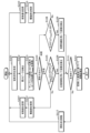
- the control circuit 70 determines whether or not the optical path length needs to be changed for each measurement, i.e., for each irradiation point of the signal light 11Lt (step S105 or S108). If the control circuit 70 determines that a change is necessary, it controls the drive unit 80 to vary the optical path length (step S107 or S110). This makes it possible to improve the measurement accuracy at each irradiation point.
- FIG. 8 is a flowchart showing a second example of the operation of the measurement device according to each embodiment.
- the example shown in FIG. 8 differs from the first example in that a process for correcting the distance is performed based on the amount of variation in the optical path length.
- the following explanation will focus on the differences from the first example, and explanations of the commonalities will be omitted or simplified.
- steps S101, S102, S103, S104, S105, S106, S107, S108, S109, S110, S111, and S112 are similar to those in the first example shown in FIG. 7, and therefore will not be described.
- Step S207 The process shown in step S207 is executed after the process shown in step S107. Specifically, the control circuit 70 records the amount of change in the optical path length.
- the amount of change may be the amount of change in the optical path length on the target side itself, or may be the amount of movement of the drive unit 80, or the amount of physical movement of the optical head 30 or the target 40.
- the control circuit 70 stores the amount of variation in a memory built into the control circuit 70 or the signal processing circuit 60. If the amount of variation can be recorded, it may be recorded in another memory provided in the measuring device 120, or in a memory provided in a device other than the measuring device 120.
- Step S210 The process shown in step S210 is executed after the process shown in step S110. Specifically, the control circuit 70 records the amount of variation in the optical path length. The specific process is the same as that in step S207.
- Step S211 8 after the measurement of all points is completed (Yes in S111), the signal processing circuit 60 reads out the amount of variation stored in the memory and corrects the distance calculated in step S106 or S109. The distance correction is performed for one or more irradiation points for which the driving unit 80 was controlled in step S107 or S110.
- the optical path length is varied by controlling the driving unit 80, so the calculated distance includes the variation in the optical path length as an offset. For example, when measuring the surface shape of the target object 40, the result obtained has offsets superimposed in places, so there is a risk that the surface shape cannot be accurately identified.
- the signal processing circuit 60 corrects the distance based on the amount of variation in the optical path length. This allows the measurement results of all points on the object 40 to be appropriately corrected, making it possible to measure, for example, the surface shape of the object 40 with high accuracy.
- correction is performed after all points are measured, but this is not limiting.
- the signal processing circuit 60 may correct the calculated distance each time it calculates the distance, i.e., immediately after step S106 or S109.
- FIG. 9A is a flowchart showing an example of pre-measurement in a third example of the measuring device according to each embodiment.
- FIG. 9B is a flowchart showing an example of main measurement in a third example of the measuring device according to each embodiment.
- the measuring device 120 performs the pre-measurement shown in FIG. 9A, and then performs the main measurement shown in FIG. 9B.
- steps S101, S102, and S103 are all similar to the processes of the first example shown in FIG. 7, and therefore descriptions thereof will be omitted.
- Step S303 The process shown in step S303 is executed after the process shown in step S 103. Specifically, the signal processing circuit 60 records the position of the acquired maximum peak (T Peak ) in the memory.
- Step S304 the control circuit 70 judges whether or not to end the pre-measurement.
- the pre-measurement is performed, for example, on all points of the object 40. All points means, for example, all measurement points on the surface of the object 40 that are planned to be measured, that is, all irradiation points that are planned to be irradiated with the signal light 11Lt. Note that, in the pre-measurement, only a portion of all points may be the measurement targets.
- Step S305 If the pre-measurement is not to be ended (No in S304), that is, if the measurement for all points is not completed, the measuring device 120 moves the irradiation point on the object 40.
- a moving stage (not shown) that supports the object 40 is used. Note that other methods may be used as long as the irradiation point can be changed.
- the process returns to step S101, and an electrical signal is obtained at the new irradiation point. Thereafter, the measuring device 120 executes the processes from step S102 onward.
- Step S306 When the preliminary measurement is completed (Yes in S304), the control circuit 70 determines the calculation method for distance conversion. Specifically, the control circuit 70 determines whether to use phase information or time information. The determination in step S306 is the same as the determination in step S104 shown in Fig. 7 or 8. The determination in step S306 may be performed at the beginning of the operation of the measuring device 120, that is, before step S101.
- Step S307 When using phase information ("phase" in S306), the control circuit 70 determines the amount of variation in the optical path length at all points based on the position T Peak of the recorded maximum peak. Specifically, the control circuit 70 determines the amount of variation in the optical path length at all points so as to satisfy T Peak ⁇ 0.45T or 0.55T ⁇ T Peak . That is, the control circuit 70 determines the amount of variation in the optical path length so that the position T Peak of the maximum peak at each irradiation point is away from the center within the sampling period. For example, when the position T Peak of the recorded maximum peak is in a range greater than 0.45T and less than 0.55T, the control circuit 70 determines the amount of variation for T Peak to deviate from the range. When the position T Peak of the recorded maximum peak satisfies T Peak ⁇ 0.45T or 0.55T ⁇ T Peak , the control circuit 70 regards the amount of variation as 0.
- Step S308 When time information is used ("time" in S306), the control circuit 70 determines the amount of variation of the optical path length at all points based on the position T Peak of the recorded maximum peak. Specifically, the control circuit 70 determines the amount of variation of the optical path length at all points so as to satisfy 0.05T ⁇ T Peak ⁇ 0.95T. That is, the control circuit 70 determines the amount of variation of the optical path length so that the position T Peak of the maximum peak at each irradiation point approaches the center within the sampling period. For example, when the position T Peak of the recorded maximum peak is in a range less than 0.05T or greater than 0.95T, the control circuit 70 determines the amount of variation for T Peak to deviate from either of these ranges. When the position T Peak of the recorded maximum peak satisfies 0.05T ⁇ T Peak ⁇ 0.95T, the control circuit 70 regards the amount of variation as 0.
- Step S309 After determining the amount of variation in step S307 or S308, the control circuit 70 records the determined amount of variation in memory. At this time, the control circuit 70 may record the amount of drive of the drive unit 80, specifically, the physical movement amount of the optical head 30 or the target object 40, as the amount of variation. By recording the amount of drive of the drive unit 80, it is possible to quickly control the drive unit 80 at the corresponding irradiation point in a short period of time.
- the control circuit 70 can control the drive unit 80 based on the determined amount of variation.
- steps S101, S102, S103, and S112 are all similar to the processes of the first example shown in FIG. 7, and therefore descriptions will be omitted.
- Step S310 When the main measurement is started, first, the control circuit 70 obtains the amount of variation corresponding to the irradiation point. Specifically, the control circuit 70 reads out the amount of variation recorded in the preliminary measurement from the memory.
- Step S311 the control circuit 70 judges whether or not it is necessary to vary the optical path length. Specifically, if the read-out variation amount is 0, the control circuit 70 judges that it is not necessary to vary. Alternatively, if the variation amount corresponding to the irradiation point is not recorded in the memory, the control circuit 70 also judges that it is not necessary to vary. If it is not necessary to vary the optical path length (No in S311), the measurement device 120 executes the process from step S101 onward.
- Step S312 If it is necessary to vary the optical path length (Yes in S311), the control circuit 70 controls the driving unit 80 based on the read-out amount of variation.
- the amount of variation is an amount determined based on a pre-measurement so that the position T Peak of the maximum peak is located in a range where the measurement accuracy is unlikely to decrease. Therefore, by controlling the driving unit 80 based on the amount of variation, the position T Peak of the maximum peak appears within an appropriate range in the main measurement, making it possible to perform measurement with high accuracy.
- the measurement device 120 executes the processes from step S101 onwards.
- Step S313 The process shown in step S313 is executed after the process shown in step S103. Specifically, the signal processing circuit 60 calculates the distance from the measuring device 120 to the irradiation point by using phase information or time information. At this time, the signal processing circuit 60 uses the information used in the preliminary measurement. That is, when the signal processing circuit 60 uses phase information in the preliminary measurement, the signal processing circuit 60 also uses phase information in the main measurement. When the signal processing circuit 60 uses time information in the preliminary measurement, the signal processing circuit 60 also uses time information in the main measurement. The specific method of calculating the distance is the same as the process shown in step S106 or S109 shown in FIG. 7.
- Step S314 After the distance from the measuring device 120 to the irradiation point is calculated in step S313, the control circuit 70 judges whether or not the measurement at all points has been completed.
- all points refers to, for example, all measurement points on the surface of the object 40 that are scheduled to be measured, that is, all irradiation points that are scheduled to be irradiated with the signal light 11Lt. If the measurement of all points has been completed (Yes in S314), the distance measurement operation by the measuring device 120 ends. On the other hand, if the measurement of all points has not been completed (No in S313), the measuring device 120 executes the process shown in step S112.
- the control circuit 70 performs a pre-measurement to measure all irradiation points on the object 40 once, and then determines the amount of variation in the optical path length based on the measurement results.
- the control circuit 70 performs a main measurement to measure all points on the object 40 again while changing the optical path length based on the determined amount of variation so as not to reduce measurement accuracy.
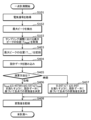
- FIG. 10 is a flow chart showing an example of a single-point measurement in the fourth example of the measurement device according to each embodiment.
- the single-point measurement shown in FIG. 10 corresponds to the pre-measurement in the third example.
- the measurement device 120 After performing the single-point measurement shown in FIG. 10, the measurement device 120 performs the main measurement shown in FIG. 9B.
- the amount of variation in the optical path length for each irradiation point is determined by the single-point measurement shown in FIG. 10.
- steps S101, S102, and S103 are all similar to the processes of the first example shown in FIG. 7, and therefore explanations will be omitted.
- Step S403 The process shown in step S403 is executed after the process shown in step S 103. Specifically, the signal processing circuit 60 records the position of the acquired maximum peak (T Peak ) in the memory.
- Step S404 the control circuit 70 reads the design data of the object 40.
- the design data of the object 40 is, for example, 3D-CAD (Computer Aided Design) data in the case of distance measurement.
- 3D-CAD Computer Aided Design
- the control circuit 70 acquires the design data by reading the design data from the memory.
- Step S405 the control circuit 70 determines the calculation method for distance conversion. Specifically, the control circuit 70 determines whether to use phase information or time information.
- the determination in step S405 is the same as the determination in step S104 shown in Fig. 7 or 8.
- the determination in step S405 may be performed at the beginning of the operation of the measuring device 120, that is, before step S101.
- Step S406 When using phase information ("phase" in S406), the control circuit 70 determines the amount of variation in the optical path length at all points based on the recorded position T Peak of the maximum peak and the design data. Specifically, the control circuit 70 determines the amount of variation in the optical path length at all points so as to satisfy T Peak ⁇ 0.45T or 0.55T ⁇ T Peak . That is, the control circuit 70 determines the amount of variation in the optical path length so that the position T Peak of the maximum peak at each irradiation point is away from the center within the sampling period. The control circuit 70 can estimate the position T Peak of the maximum peak at all remaining points that have not been measured from the position T Peak of the maximum peak at one measured point by referring to the design data. Therefore, the control circuit 70 can determine the amount of variation in the optical path length at all points by using the estimation result.
- the specific determination method is the same as step S307 shown in FIG. 9A.
- Step S407 When time information is used ("time" in S405), the control circuit 70 determines the amount of variation in the optical path length at all points based on the recorded position T Peak of the maximum peak and the design data. Specifically, the control circuit 70 determines the amount of variation in the optical path length at all points so as to satisfy 0.05T ⁇ T Peak ⁇ 0.95T. That is, the control circuit 70 determines the amount of variation in the optical path length so that the position T Peak of the maximum peak at each irradiation point approaches the center within the sampling period. As in step S406, the control circuit 70 can estimate the position T Peak of the maximum peak at all remaining points that have not been measured from the position T Peak of the maximum peak at one measured point by referring to the design data. Therefore, the control circuit 70 can determine the amount of variation in the optical path length at all points by using the estimation result.
- the specific determination method is the same as step S308 shown in FIG. 9A.
- Step S408 After determining the amount of variation in step S406 or S407, the control circuit 70 records the determined amount of variation in memory. At this time, the control circuit 70 may record the amount of drive of the drive unit 80, specifically, the physical movement amount of the optical head 30 or the target object 40, as the amount of variation. By recording the amount of drive of the drive unit 80, it is possible to quickly control the drive unit 80 at the corresponding irradiation point in a short period of time.
- the control circuit 70 can control the drive unit 80 based on the determined amount of variation.
- the time required for measurement can be shortened compared to when a pre-measurement is performed.
- the pulsed light source 10 does not have to be an optical comb laser. That is, the pulsed light source 10 does not have to include a resonator, and may be, for example, a laser diode (LD) or a light emitting diode (LED) that repeatedly emits pulsed light.
- LD laser diode
- LED light emitting diode
- the example of moving the target object 40 or the optical head 30 has been shown as an example of the driving unit 80 that changes the optical path length, but this is not limiting.
- the driving unit 80 may change the optical path length by utilizing the expansion and contraction of the optical fiber.
- the driving unit 80 may be a temperature adjustment element that heats or cools the optical fiber.
- a temperature adjustment element a Peltier element, a blower, a heater, etc. can be used.
- the ranges of less than 0.05T or greater than 0.95T have been given as the ends of the sampling period, but the present invention is not limited to these.
- the upper limit value on the start side of the sampling period may be a value in the range greater than 0 and less than 0.10T.
- the lower limit value on the end side of the sampling period may be a value in the range of 0.90T or greater and less than T.
- the range of greater than 0.45T and less than 0.55T has been given as the central range of the sampling period, but is not limited to this.
- the lower limit of the central range may be a value greater than 0.40T and less than 0.50T.
- the upper limit of the central range may be a value greater than 0.50T and less than 0.60T.
- the upper and lower limits may be changed depending on the length of the sampling period.
- processing performed by a specific processing unit may be executed by another processing unit.
- the order of multiple processes may be changed, or multiple processes may be executed in parallel.
- the processing described in the above embodiment may be realized by centralized processing using a single device (system), or may be realized by distributed processing using multiple devices.
- the processor that executes the above program may be either single or multiple. In other words, centralized processing or distributed processing may be performed.
- all or part of the components such as the signal processing circuit 60 and the control circuit 70 may be configured with dedicated hardware, or may be realized by executing a software program suitable for each component.
- Each component may be realized by a program execution unit such as a CPU (Central Processing Unit) or a processor reading and executing a software program recorded on a recording medium such as a HDD (Hard Disk Drive) or semiconductor memory.
- a program execution unit such as a CPU (Central Processing Unit) or a processor reading and executing a software program recorded on a recording medium such as a HDD (Hard Disk Drive) or semiconductor memory.
- components such as the signal processing circuit 60 and the control circuit 70 may be composed of one or more electronic circuits.
- Each of the one or more electronic circuits may be a general-purpose circuit or a dedicated circuit.
- the electronic circuit or circuits may include, for example, a semiconductor device, an IC, or an LSI.
- the IC or LSI may be integrated on one chip or on multiple chips.
- an FPGA that is programmed after the LSI is manufactured can be used for the same purpose.
- the general or specific aspects of the present disclosure may be realized as a system, an apparatus, a method, an integrated circuit, or a computer program.
- the invention may be realized as a computer-readable non-transitory recording medium, such as an optical disk, a HDD, or a semiconductor memory, on which the computer program is stored.
- the invention may also be realized as any combination of a system, an apparatus, a method, an integrated circuit, a computer program, and a recording medium.
- the present disclosure may be used, for example, for distance measurement and displacement measurement.
- the measuring device and measuring method according to the present disclosure may be used in a displacement meter and a shape inspection device.
Landscapes
- Physics & Mathematics (AREA)
- Engineering & Computer Science (AREA)
- General Physics & Mathematics (AREA)
- Radar, Positioning & Navigation (AREA)
- Remote Sensing (AREA)
- Computer Networks & Wireless Communication (AREA)
- Electromagnetism (AREA)
- Optical Radar Systems And Details Thereof (AREA)
Priority Applications (3)
| Application Number | Priority Date | Filing Date | Title |
|---|---|---|---|
| CN202380090123.6A CN120457319A (zh) | 2023-01-27 | 2023-12-25 | 计测装置及计测方法 |
| JP2024572910A JPWO2024157700A1 (https=) | 2023-01-27 | 2023-12-25 | |
| US19/260,694 US20250334679A1 (en) | 2023-01-27 | 2025-07-07 | Measurement device and measurement method |
Applications Claiming Priority (2)
| Application Number | Priority Date | Filing Date | Title |
|---|---|---|---|
| JP2023-010992 | 2023-01-27 | ||
| JP2023010992 | 2023-01-27 |
Related Child Applications (1)
| Application Number | Title | Priority Date | Filing Date |
|---|---|---|---|
| US19/260,694 Continuation US20250334679A1 (en) | 2023-01-27 | 2025-07-07 | Measurement device and measurement method |
Publications (1)
| Publication Number | Publication Date |
|---|---|
| WO2024157700A1 true WO2024157700A1 (ja) | 2024-08-02 |
Family
ID=91970419
Family Applications (1)
| Application Number | Title | Priority Date | Filing Date |
|---|---|---|---|
| PCT/JP2023/046352 Ceased WO2024157700A1 (ja) | 2023-01-27 | 2023-12-25 | 計測装置および計測方法 |
Country Status (4)
| Country | Link |
|---|---|
| US (1) | US20250334679A1 (https=) |
| JP (1) | JPWO2024157700A1 (https=) |
| CN (1) | CN120457319A (https=) |
| WO (1) | WO2024157700A1 (https=) |
Cited By (1)
| Publication number | Priority date | Publication date | Assignee | Title |
|---|---|---|---|---|
| WO2025225294A1 (ja) * | 2024-04-24 | 2025-10-30 | パナソニックIpマネジメント株式会社 | 計測装置 |
Citations (3)
| Publication number | Priority date | Publication date | Assignee | Title |
|---|---|---|---|---|
| JP2014185956A (ja) * | 2013-03-25 | 2014-10-02 | Aisin Seiki Co Ltd | 距離測定装置 |
| JP2016048188A (ja) * | 2014-08-27 | 2016-04-07 | 国立大学法人電気通信大学 | 距離測定装置 |
| WO2021261240A1 (ja) * | 2020-06-26 | 2021-12-30 | パナソニックIpマネジメント株式会社 | デュアル光周波数コム発生装置および計測装置 |
-
2023
- 2023-12-25 JP JP2024572910A patent/JPWO2024157700A1/ja active Pending
- 2023-12-25 WO PCT/JP2023/046352 patent/WO2024157700A1/ja not_active Ceased
- 2023-12-25 CN CN202380090123.6A patent/CN120457319A/zh active Pending
-
2025
- 2025-07-07 US US19/260,694 patent/US20250334679A1/en active Pending
Patent Citations (3)
| Publication number | Priority date | Publication date | Assignee | Title |
|---|---|---|---|---|
| JP2014185956A (ja) * | 2013-03-25 | 2014-10-02 | Aisin Seiki Co Ltd | 距離測定装置 |
| JP2016048188A (ja) * | 2014-08-27 | 2016-04-07 | 国立大学法人電気通信大学 | 距離測定装置 |
| WO2021261240A1 (ja) * | 2020-06-26 | 2021-12-30 | パナソニックIpマネジメント株式会社 | デュアル光周波数コム発生装置および計測装置 |
Cited By (1)
| Publication number | Priority date | Publication date | Assignee | Title |
|---|---|---|---|---|
| WO2025225294A1 (ja) * | 2024-04-24 | 2025-10-30 | パナソニックIpマネジメント株式会社 | 計測装置 |
Also Published As
| Publication number | Publication date |
|---|---|
| US20250334679A1 (en) | 2025-10-30 |
| CN120457319A (zh) | 2025-08-08 |
| JPWO2024157700A1 (https=) | 2024-08-02 |
Similar Documents
| Publication | Publication Date | Title |
|---|---|---|
| CN102494615B (zh) | 基于飞秒光频梳的台阶距离测量装置及方法 | |
| JP6765579B2 (ja) | 光測距装置及び加工装置 | |
| CN110691983A (zh) | 具有结构光及集成照明和检测的基于lidar的3-d成像 | |
| US10371803B2 (en) | Distance measuring device and method for calibrating the same | |
| US9329027B2 (en) | Measuring unit, measuring system and method for determining a relative position and relative orientation | |
| US7446881B2 (en) | System, apparatus, and method for determining temperature/thickness of an object using light interference measurements | |
| JP2015094760A5 (https=) | ||
| JP2015094760A (ja) | 合成波レーザー測距センサ及び方法 | |
| US20240004044A1 (en) | Apparatus and method for measuring distant to and/or velocity of physical object | |
| JPH01502296A (ja) | 干渉計方式で長さを測定するレーザ干渉測距計 | |
| US20090302223A1 (en) | Method of measuring terahertz wave and terahertz spectroscopic apparatus | |
| US20250334679A1 (en) | Measurement device and measurement method | |
| JP4654996B2 (ja) | テラヘルツ波応答測定装置 | |
| US12517222B2 (en) | Data correction apparatus, measurement system, and correction method | |
| JP6039493B2 (ja) | 波長掃引光源の光周波数校正方法とそのプログラム及び記憶媒体、光周波数校正装置、光干渉断層計測装置 | |
| JP7128516B2 (ja) | デュアルコム分光法における干渉信号の測定方法 | |
| US20250096516A1 (en) | Laser device | |
| US10386466B2 (en) | Distance measuring device and distance measuring method | |
| TWI880926B (zh) | 非接觸式晶圓厚度測定裝置 | |
| JP7303671B2 (ja) | 電子装置及び距離計測方法 | |
| US12379494B2 (en) | Optical distance measurement device and machining device | |
| JP7592305B2 (ja) | 光波距離計及び光コム距離計 | |
| JP2021067645A (ja) | 計測装置、計測方法、及びプログラム | |
| WO2025150355A1 (ja) | 計測装置および計測方法 | |
| KR102844795B1 (ko) | 광주파수빗 기반 무교정 파장측정기 및 이의 동작 방법 |
Legal Events
| Date | Code | Title | Description |
|---|---|---|---|
| 121 | Ep: the epo has been informed by wipo that ep was designated in this application |
Ref document number: 23918654 Country of ref document: EP Kind code of ref document: A1 |
|
| WWE | Wipo information: entry into national phase |
Ref document number: 202380090123.6 Country of ref document: CN |
|
| ENP | Entry into the national phase |
Ref document number: 2024572910 Country of ref document: JP Kind code of ref document: A |
|
| WWE | Wipo information: entry into national phase |
Ref document number: 2024572910 Country of ref document: JP |
|
| WWP | Wipo information: published in national office |
Ref document number: 202380090123.6 Country of ref document: CN |
|
| NENP | Non-entry into the national phase |
Ref country code: DE |
|
| 122 | Ep: pct application non-entry in european phase |
Ref document number: 23918654 Country of ref document: EP Kind code of ref document: A1 |