WO2024157633A1 - モータ制御システム、永久磁石モータ、永久磁石モータの製造方法 - Google Patents
モータ制御システム、永久磁石モータ、永久磁石モータの製造方法 Download PDFInfo
- Publication number
- WO2024157633A1 WO2024157633A1 PCT/JP2023/044534 JP2023044534W WO2024157633A1 WO 2024157633 A1 WO2024157633 A1 WO 2024157633A1 JP 2023044534 W JP2023044534 W JP 2023044534W WO 2024157633 A1 WO2024157633 A1 WO 2024157633A1
- Authority
- WO
- WIPO (PCT)
- Prior art keywords
- rotor core
- conductor
- permanent magnet
- insertion hole
- control system
- Prior art date
- Legal status (The legal status is an assumption and is not a legal conclusion. Google has not performed a legal analysis and makes no representation as to the accuracy of the status listed.)
- Ceased
Links
Images








Classifications
-
- H—ELECTRICITY
- H02—GENERATION; CONVERSION OR DISTRIBUTION OF ELECTRIC POWER
- H02K—DYNAMO-ELECTRIC MACHINES
- H02K1/00—Details of the magnetic circuit
- H02K1/06—Details of the magnetic circuit characterised by the shape, form or construction
- H02K1/22—Rotating parts of the magnetic circuit
- H02K1/27—Rotor cores with permanent magnets
- H02K1/2706—Inner rotors
- H02K1/272—Inner rotors the magnetisation axis of the magnets being perpendicular to the rotor axis
- H02K1/274—Inner rotors the magnetisation axis of the magnets being perpendicular to the rotor axis the rotor consisting of two or more circumferentially positioned magnets
- H02K1/2753—Inner rotors the magnetisation axis of the magnets being perpendicular to the rotor axis the rotor consisting of two or more circumferentially positioned magnets the rotor consisting of magnets or groups of magnets arranged with alternating polarity
- H02K1/276—Magnets embedded in the magnetic core, e.g. interior permanent magnets [IPM]
-
- H—ELECTRICITY
- H02—GENERATION; CONVERSION OR DISTRIBUTION OF ELECTRIC POWER
- H02P—CONTROL OR REGULATION OF ELECTRIC MOTORS, ELECTRIC GENERATORS OR DYNAMO-ELECTRIC CONVERTERS; CONTROLLING TRANSFORMERS, REACTORS OR CHOKE COILS
- H02P5/00—Arrangements specially adapted for regulating or controlling the speed or torque of two or more electric motors
- H02P5/74—Arrangements specially adapted for regulating or controlling the speed or torque of two or more electric motors controlling two or more AC dynamo-electric motors
Definitions
- the disclosed embodiments relate to a motor control system, a permanent magnet motor, and a method for manufacturing a permanent magnet motor.
- Patent document 1 describes a motor drive system in which multiple induction synchronous motors are connected in parallel to a single inverter, and each induction synchronous motor operates a drive device in synchronous operation.
- the present invention was made in consideration of these problems, and aims to provide a motor control system, a permanent magnet motor, and a method for manufacturing a permanent magnet motor that can suppress the occurrence of disturbances.
- a motor control system has a plurality of permanent magnet motors and an inverter for driving the plurality of permanent magnet motors, the permanent magnet motor having a rotatably supported rotor core, a plurality of permanent magnets provided inside the rotor core, conductor insertion holes formed inside the rotor core radially outward of the permanent magnets, and conductors inserted into the conductor insertion holes.
- a permanent magnet motor which has a rotatably supported rotor core, a plurality of permanent magnets provided inside the rotor core, and conductor insertion holes formed radially outward from the permanent magnets inside the rotor core, one for each of the magnetic poles, at each of the magnetic poles formed in the rotor core by the plurality of permanent magnets, and a conductor inserted into the conductor insertion hole.
- a method for manufacturing a permanent magnet motor which includes fixing a rotor core to a shaft, inserting conductors into a plurality of conductor insertion holes formed inside the rotor core, inserting permanent magnets into a plurality of magnet insertion holes formed inside the rotor core radially inward from the conductor insertion holes, and connecting the ends of the conductors on one axial side and the other axial side with a ring-shaped connecting member.
- the motor control system of the present invention can suppress the occurrence of motor disturbances.
- FIG. 1 is a diagram illustrating an example of an overall configuration of a motor control system according to an embodiment.
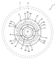
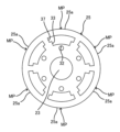
- 1 is a side view illustrating an example of a configuration of a permanent magnet motor according to an embodiment, as viewed from an axial direction.
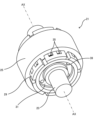
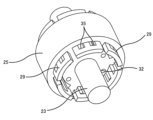
- FIG. 2 is a perspective view illustrating an example of the structure of a rotor of a permanent magnet motor.
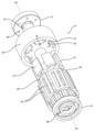
- FIG. 2 is an exploded perspective view illustrating an example of a rotor structure.
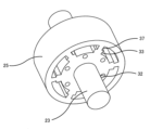
- 10A to 10C are perspective views illustrating an example of an assembly process for a rotor.
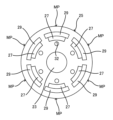
- 10A to 10C are side views seen from the axial direction, illustrating an example of an assembly process of the rotor.
- 10A to 10C are perspective views illustrating an example of an assembly process for a rotor.
- 10A to 10C are side views seen from the axial direction, illustrating an example of an assembly process of the rotor.
- 10A to 10C are perspective views illustrating an example of an assembly process for a rotor.
- 10A to 10C are side views seen from the axial direction, illustrating an example of an assembly process of the rotor.
- 10A to 10C are perspective views illustrating an example of an assembly process for a rotor.
- 10A to 10C are side views seen from the axial direction, illustrating an example of an assembly process of the rotor.
- 4 is a cross-sectional view illustrating an example of a fixing structure of a connection member.
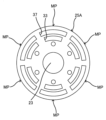
- FIG. 13 is a side view, viewed from the axial direction, illustrating an example of a rotor core structure in a modified example in which the magnet insertion holes and the conductor insertion holes are separated.
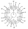
- FIG. 13 is a side view, viewed from the axial direction, illustrating an example of a rotor core structure in a modified example in which conductors are arranged in multiple layers in the radial direction.
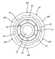
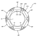
- FIG. 11 is a cross-sectional view in a direction perpendicular to the axial direction illustrating an example of a rotor structure in a modified example in which the outer periphery of the rotor core is cylindrical.
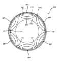
- FIG. 13 is a cross-sectional view in a direction perpendicular to the axial direction, illustrating another example of a rotor structure in a modified example in which the outer periphery of the rotor core is cylindrical.
- FIG. 13 is a cross-sectional view in a direction perpendicular to the axial direction illustrating an example of a rotor structure in a modified example in which a cylindrical member is provided on the outer periphery of a rotor core.
- FIG. 13 is a cross-sectional view showing an example of a cross-sectional structure of a conductor in a modified example in which the thickness of the conductor is changed in the axial direction.
- FIG. 13 is a cross-sectional view showing an example of a structure of a rotor core in a modified example in which permanent magnets are filled into slits in a conductor.
- FIG. 13 is a cross-sectional view showing an example of a structure of a rotor core in a modified example in which slits in a conductor are filled with core members.
- Fig. 1 shows an example of the overall configuration of a motor control system 1 according to an embodiment.
- the motor control system 1 has a plurality of permanent magnet motors 3 and one inverter 5 for driving the plurality of permanent magnet motors 3.
- the number of permanent magnet motors 3 is not particularly limited as long as there is a plurality of them.
- Fig. 1 shows, for example, a case where there are three permanent magnet motors.
- the inverter 5 has a converter unit 7, a smoothing capacitor 9, an inverter unit 11, and a control unit 13.
- the converter unit 7 converts AC power supplied from an AC power source 15 into DC power.
- the smoothing capacitor 9 smoothes the DC power converted by the converter unit 7.
- the inverter unit 11 converts DC power into AC power and supplies it to each of the multiple permanent magnet motors 3 to drive them.
- the control unit 13 outputs a control signal S, such as a PWM signal, to the inverter unit 11 based on a command from a higher-level controller (not shown), and controls the inverter unit 11.
- the motor control system 1 may have multiple inverters 5 as long as it includes a configuration in which multiple permanent magnet motors 3 are controlled by one inverter 5.
- the motor control system 1 controls multiple permanent magnet motors 3 using one inverter 5. For this reason, there is a possibility that disturbances such as load imbalance between the permanent magnet motors 3 may cause the control of the permanent magnet motors 3 to become unstable.
- disturbances such as load imbalance between the permanent magnet motors 3 may cause the control of the permanent magnet motors 3 to become unstable.
- this embodiment by generating a damping effect due to induced torque in each permanent magnet motor 3, disturbances that cause the control of the permanent magnet motors 3 to become unstable can be suppressed, thereby stabilizing the system.
- the detailed structure of the permanent magnet motor 3 will be described below.
- Figures 2 to 4 show an example of the configuration of the permanent magnet motor 3.
- Figure 2 is a side view from the axial direction showing an example of the configuration of the permanent magnet motor 3, with the frame and stator simplified and indicated by dashed lines.
- Figure 3 is a perspective view showing an example of the structure of the rotor of the permanent magnet motor 3
- Figure 4 is an exploded perspective view showing an example of the rotor structure.
- the permanent magnet motor 3 has a frame 17, a stator 19, and a rotor 21.
- the stator 19 is provided on the inner circumference of the cylindrical frame 17.
- the stator 19 has a stator core and multiple stator windings.
- the rotor 21 has a shaft 23, a rotor core 25, a plurality of permanent magnets 27, a plurality of conductors 29, and two connecting members 31.
- the shaft 23 is supported for free rotation around the rotation axis AX by a load side bearing (not shown) provided on the load side of the frame 17 and a non-load side bearing (not shown) provided on the non-load side of the frame 17.
- the rotor core 25 is formed by stacking thin disk-shaped plates made of a magnetic material in the axial direction.
- the rotor core 25 is supported rotatably around the rotation axis AX by being fixed to the outer periphery of the shaft 23.
- the rotor core 25 has, for example, six magnetic poles MP formed by permanent magnets 27, and is formed in a cylindrical shape.
- the rotor core 25 has adjustment holes 32 formed at multiple locations in the rotation direction (for example, one at each magnetic pole MP, for a total of six locations) for adjusting the weight balance in the rotation direction.
- the rotor core 25 may be formed in a shape in which each magnetic pole MP bulges outward and the spaces between the magnetic poles are recessed inward, that is, in a so-called petal shape, by setting the radius of curvature of the outer periphery 25a of each magnetic pole MP to be smaller than the radius of the rotor core 25.
- the permanent magnets 27 are provided inside the rotor core 25.
- Each permanent magnet 27 is generally arc-shaped, with a convex outer periphery and a concave inner periphery, as viewed from the axial direction.
- the axial length of the permanent magnets 27 is generally equal to the axial length of the rotor core 25.
- the number of permanent magnets 27 is not particularly limited as long as a predetermined number (e.g., six) of magnetic poles MP are formed in the rotor core 25, but in this embodiment, six permanent magnets are provided, the same number as the magnetic poles MP.
- each permanent magnet 27 is inserted into a magnet insertion hole 33 of approximately the same shape provided inside the rotor core 25.
- the magnet insertion hole 33 is formed radially inward from a conductor insertion hole 37 described later.
- the conductors 29 are provided inside the rotor core 25.
- Each conductor 29 is formed in a plate shape whose dimension in the rotation direction of the rotor core 25 is larger than its dimension in the radial direction.
- each conductor 29 is curved along the outer peripheral shape of the outer peripheral surface 25a of each magnetic pole MP of the rotor core 25.
- the axial length of the conductor 29 is longer than the axial length of the rotor core 25, and both axial sides of the conductor 29 are arranged to protrude from the end of the rotor core 25 by a predetermined length.
- the material of the conductor 29 is not particularly limited as long as it is a conductive material, and is, for example, made of copper, which has a higher conductivity than aluminum. It may be made of a material other than copper that has a high conductivity, such as brass.
- the number of conductors 29 is not particularly limited, and, for example, six conductors are provided, which is the same number as the magnetic poles MP.
- each conductor 29 has a slit 35 formed therein, which penetrates the conductor 29 in the radial direction and extends in an axial direction perpendicular to the radial direction.
- the axial length of the slit 35 is longer than the axial length of the rotor core 25, and the conductor 29 is arranged so that both ends of the axial direction of the slit 35 slightly protrude from the ends of the rotor core 25.
- the number of slits 35 formed in one conductor 29 may be one or more. In this embodiment, for example, two slits 35 are formed in each conductor 29. Note that the slits 35 do not necessarily have to be formed.
- the conductor 29 having the above configuration may be manufactured by forming the slits 35 in a rectangular flat copper plate by pressing, and then bending the plate.
- each conductor 29 is inserted into a conductor insertion hole 37 of approximately the same shape formed inside the rotor core 25.
- the conductor insertion hole 37 is formed inside the rotor core 25, radially outward of the permanent magnets 27.
- the conductor insertion hole 37 is formed so that one conductor insertion hole 37 is arranged for each magnetic pole MP at each magnetic pole MP of the multiple (e.g., six) magnetic poles MP formed in the rotor core 25 by the multiple (e.g., six) permanent magnets 27. That is, in this embodiment, the number of conductors 29 is the same as the number of permanent magnets 27.
- the magnet insertion hole 33 and the conductor insertion hole 37 are connected to each other and are formed as a single connected hole.
- connection members 31 are arranged on both axial sides of the rotor core 25.
- the connection members 31 are ring-shaped members that connect the conductors 29 that are spaced apart and spaced apart at equal intervals in the circumferential direction.
- the material of the connection members 31 is not particularly limited as long as it is a conductive material, but for example, it is made of copper, which has a higher conductivity than aluminum. It may be made of a material other than copper that has a higher conductivity, such as brass.
- the radially outer end of the connection member 31 contacts the inner circumferential surface of each conductor 29, and the radially inner end of the connection member 31 contacts the outer circumferential surface of the shaft 23.
- the connection member 31 has openings 39 formed at multiple circumferential locations (for example, six locations) that correspond to the adjustment holes 32 of the rotor core 25 described above. The openings 39 are equal to or larger in size than the adjustment holes 32.
- the "axial direction” refers to a direction that is approximately parallel to the rotation axis AX of the shaft 23
- the "rotation direction” or “circumferential direction” refers to a rotation direction or circumferential direction with the rotation axis AX as the center of rotation
- the "radial direction” refers to a radial direction with the rotation axis AX as the center.
- Rotor assembly process> 5 to 12 show an example of a process for assembling the rotor 21.
- the process for assembling the rotor 21 is an example of a method for manufacturing the permanent magnet motor 3.
- the rotor core 25 is fitted to the outer circumference of the shaft 23, thereby fixing the rotor core 25 to the shaft 23.
- magnet insertion holes 33 and conductor insertion holes 37 are formed, one each at a position corresponding to each magnetic pole MP formed by the permanent magnets 27 to be inserted later. That is, in this example, six magnet insertion holes 33 and six conductor insertion holes 37 are formed.
- the conductor insertion holes 37 are arranged radially outward of the magnet insertion holes 33.
- the magnet insertion holes 33 and the conductor insertion holes 37 are connected to each other and formed as a single connected hole.
- the rotor core 25 has the aforementioned adjustment holes 32 formed at multiple locations in the rotational direction (for example, one for each magnetic pole MP, for a total of six locations).
- multiple (e.g., six) conductors 29 are inserted into each of the multiple conductor insertion holes 37 formed inside the rotor core 25.
- Each conductor 29 is inserted axially into the conductor insertion hole 37 and fixed, for example, by adhesive.
- Each conductor 29 is fixed so that both axial ends of the slit 35 protrude from the ends of the rotor core 25.
- a permanent magnet 27 is inserted into each of the multiple magnet insertion holes 33 formed inside the rotor core 25, radially inward from the conductor insertion hole 37.
- Each permanent magnet 27 is inserted axially into the magnet insertion hole 33 and fixed, for example, by adhesive. This forms multiple (e.g., six) magnetic poles MP in the rotor core 25.
- a ring-shaped connecting member 31 is fitted and fixed between the multiple conductors 29 protruding from the end of the rotor core 25 and the shaft 23.
- the connecting member 31 is fixed so that its radially outer end contacts the inner circumferential surface of each conductor 29 and its radially inner end contacts the outer circumferential surface of the shaft 23.
- the ends on one axial side and the other axial side of the multiple conductors 29 arranged circumferentially spaced apart are electrically connected by the ring-shaped connecting member 31.
- the connecting member 31 is arranged so that the position of the opening 39 approximately coincides with the position of the adjustment hole 32 of the rotor core 25.
- FIG. 13 shows an example of a fixing structure of the connection member 31.
- connection member 31 has a first contact portion 31a, a second contact portion 31b, and a linking portion 31c.
- the rotor core 25 is formed by stacking disk-shaped thin plates made of a magnetic material in the axial direction, and the first contact portion 31a abuts against the thin plate at the axial end of the rotor core 25.
- the second contact portion 31b is formed by bending the radial inner side of the first contact portion 31a, and contacts the outer circumferential surface of the shaft 23 to which the rotor core 25 is fixed.
- the second contact portion 31b is formed, for example, by drawing a ring-shaped plate member, and narrows radially inward as it moves away from the first contact portion 31a, and the portion with the smallest opening fits into the outer circumferential surface of the shaft 23.
- the linking portion 31c is formed by bending the radial outer side of the first contact portion 31a, and is linked to the multiple conductors 29 from the radial inner side.
- the connecting portion 31c is formed, for example, by drawing a ring-shaped plate member. In this embodiment, the connecting portion 31c and the conductor 29 are joined, for example, by laser welding. In FIG. 13, the joint formed by the laser welding is illustrated as joint 43.
- the permanent magnet motor 3 of the motor control system 1 of this embodiment has a plurality of permanent magnets 27 provided inside the rotor core 25, a conductor insertion hole 37 formed inside the rotor core 25 radially outward of the permanent magnets 27, and a conductor 29 inserted into the conductor insertion hole 37.
- a disturbance such as an imbalance in the load between the permanent magnet motors 3 due to a load fluctuation occurs, an eddy current flows in the conductor 29, and a damper effect due to an induced torque can be generated by an interaction between the magnetic flux generated by the stator winding (not shown) and the eddy current in the conductor 29.
- the conductor 29 is arranged radially outward of the permanent magnets 27, the generation of eddy currents is promoted during load fluctuations, and the wildness suppression effect can be enhanced.
- the demagnetization of the permanent magnets due to the starting current can be weakened by the reaction magnetic flux due to the eddy current, so that the demagnetization of the permanent magnets 27 can be reduced.
- the conductor 29 is embedded in the rotor core 25, it is possible to reduce the influence of time harmonics, for example, when the motor is driven by an inverter. As a result, it is possible to reduce the temperature rise of the permanent magnet motor 3 due to heat generation in the conductor 29, the demagnetization of the permanent magnets 27, and the eddy current loss in the conductor 29.
- the conductor insertion holes 37 may be formed so that one is arranged for each magnetic pole MP at each magnetic pole MP formed in the rotor core 25 by the multiple permanent magnets 27.
- the work of inserting the conductor 29 is easier and workability can be improved compared to, for example, when multiple conductor insertion holes 37 are formed for one magnetic pole MP.
- the permanent magnet motor 3 may have a magnet insertion hole 33 formed inside the rotor core 25 radially inward of the conductor insertion hole 37, into which the permanent magnet 27 is inserted, in which case the magnet insertion hole 33 and the conductor insertion hole 37 may be connected at each magnetic pole of the multiple magnetic poles MP.
- the insertion of the conductor 29 and permanent magnet 27 is easier than when the magnet insertion hole 33 and the conductor insertion hole 37 are separate at each magnetic pole MP of the rotor core 25, improving workability.
- the conductor 29 may be formed in a plate shape whose dimension in the direction of rotation of the rotor core 25 is greater than its radial dimension.
- the conductor 29 can efficiently cover the radial outside of the permanent magnet 27, promoting the generation of eddy currents during load fluctuations and increasing the damping effect to further enhance the anti-harmony effect.
- the surface area of the conductor 29 can be increased, the degree of freedom in the inclination angle (skew) of slits formed in the conductor 29 can be improved.
- the conductor 29 may be formed with one or more slits 35 that penetrate the conductor 29 in the radial direction and extend in an elongated manner in a direction perpendicular to the radial direction. In this case, it is possible to prevent the eddy currents generated in the conductor 29 from becoming excessive, and to improve the heat dissipation effect of the conductor 29. This makes it possible to effectively suppress heat generation in the conductor 29.
- the permanent magnet motor 3 may have ring-shaped connecting members 31 arranged on both axial sides of the rotor core 25 and connecting the multiple conductors 29.
- both ends of the multiple conductors 29 can be electrically connected and short-circuited, which can promote the generation of eddy currents during load fluctuations, increase the damping effect, and further improve the anti-harmony effect.
- the rotor core 25 is constructed by stacking disk-shaped thin plates made of a magnetic material in the axial direction, and the connection members 31 may contact the thin plates at the axial ends of the rotor core 25. In this case, both axial ends of the rotor core 25 can be held down by the connection members 31, preventing the thin plates that make up the rotor core 25 from peeling off due to centrifugal force.
- connection member 31 may contact the outer circumferential surface of the shaft 23 to which the rotor core 25 is fixed. In this case, the connection member 31 can be tensioned between the conductor 29 and the shaft 23 to suppress vibration of the conductor 29.
- connection member 31 may have a first contact portion 31a that contacts the axial end of the rotor core 25, a second contact portion 31b that is formed by bending the radial inner side of the first contact portion 31a and that contacts the outer circumferential surface of the shaft 23 to which the rotor core 25 is fixed, and a connecting portion 31c that is formed by bending the radial outer side of the first contact portion 31a and that is connected to the multiple conductors 29.
- connection member 31 having the first contact portion 31a, the second contact portion 31b, and the linking portion 31c can be formed, for example, by drawing a ring-shaped plate member, and the damper structure can be realized by connecting the connection member 31 to a plurality of conductors 29.
- the damper structure By being able to realize the damper structure by processing the parts in this way, it is possible to improve the workability of the parts and the assembly of the rotor compared to, for example, a case in which the secondary conductor of an induction motor is integrally formed by an aluminum die casting method.
- the rotor core 25 may have adjustment holes 32 formed at multiple locations in the rotational direction to adjust the weight balance in the rotational direction, and in this case, the first contact portion 31a of the connection member 31 may have openings 39 formed at positions corresponding to the adjustment holes 32.
- a balance adjustment material such as resin can be injected into the adjustment holes 32 of the rotor core 25 through the openings 39 of the connecting members 31. This makes it easier to adjust the weight balance and improves workability.
- the manufacturing method of the permanent magnet motor 3 includes fixing the rotor core 25 to the shaft 23, inserting conductors 29 into a plurality of conductor insertion holes 37 formed inside the rotor core 25, inserting permanent magnets 27 into a plurality of magnet insertion holes 33 formed inside the rotor core 25 radially inward from the conductor insertion holes 37, and connecting the ends of the plurality of conductors 29 on one axial side and the other axial side with a ring-shaped connecting member 31.
- a damper structure can be realized by assembling multiple conductors 29 and connecting members 31 to the rotor core 25.
- a damper structure By being able to realize a damper structure by assembling multiple parts in this way, it is possible to improve the workability of parts and the assembly of the rotor compared to, for example, a case in which the secondary conductor of an induction motor is integrally molded by an aluminum die casting method.
- Figure 14 shows an example of the structure of rotor core 25A according to this modified example. As shown in Figure 14, in rotor core 25A, magnet insertion holes 33 and conductor insertion holes 37 are formed radially separated. This modified example can also achieve the same effects as the previously described embodiment.
- Figure 15 shows an example of the structure of the rotor core 25 according to this modified example.
- the conductors 29 are arranged in multiple layers radially in the conductor insertion holes 37 at each magnetic pole MP.
- two layers are arranged, and the radial thickness of the conductors 29 is thinner than that of the conductors 29 in the above embodiment.
- by stacking two thin conductors 29, processing of the conductors 29 is easier than when using a single thick conductor 29.
- the number of layers of the conductor 29 is not limited to two, and three or more layers may be arranged in the radial direction.
- the material of the conductor 29 may be changed for each layer, or the radial thickness of the conductor 29 may be changed for each layer. In this case, the damping effect during load fluctuations can be optimized, and the degree of freedom in designing the damper structure can be improved.
- the shape of the permanent magnet 27 when viewed from the axial direction is described as being approximately an arc shape with a bulge on the outer periphery and a concave on the inner periphery, but the shape of the permanent magnet 27 may be a shape other than the above.
- FIG. 16 shows an example of the structure of a rotor 21C according to this modified example.
- the rotor 21C according to this modified example has a rotor core 25C.
- the rotor core 25C is formed in a cylindrical shape with an approximately circular outer periphery when viewed from the axial direction.
- the rotor core 25C is configured so that the circumferential position of the magnetic poles MP and the circumferential position of the conductors 29 approximately coincide with each other.
- multiple (e.g., six) magnet insertion holes 33C are formed, each of which has an approximately arc-shaped shape with a concave outer periphery and a bulging inner periphery when viewed from the axial direction, and permanent magnets 27C of approximately the same shape are inserted into each of the magnet insertion holes 33C.
- multiple (e.g., six) conductor insertion holes 37C are formed radially outward from the magnet insertion hole 33C, and are arc-shaped and follow the outer peripheral shape of the rotor core 25C.
- Conductors 29C of approximately the same shape are inserted into the conductor insertion holes 37C.
- the conductors 29C have the same configuration as the conductor 29 described above.
- the magnet insertion holes 33C and the conductor insertion holes 37C are separated. Holes 45 are formed between the circumferentially adjacent permanent magnets 27C to reduce leakage magnetic flux.
- the rotor 21D according to this modified example has a rotor core 25D.
- the rotor core 25D is formed in a cylindrical shape with an outer circumferential shape viewed from the axial direction being approximately circular.
- the rotor core 25D is configured so that the circumferential position of the magnetic pole MP does not coincide with the circumferential position of the conductor 29D.
- a plurality of (e.g., six) magnet insertion holes 33D having an approximately flat plate shape are formed, and permanent magnets 27D having approximately the same shape are inserted into each of the magnet insertion holes 33D.
- a plurality of (e.g., six) conductor insertion holes 37D having an arc shape approximately following the outer circumferential shape of the rotor core 25D are formed at a position radially outside the magnet insertion holes 33D and shifted approximately 30 degrees in the circumferential direction, and conductors 29D having approximately the same shape are inserted into each of the conductor insertion holes 37D.
- Conductor 29D has the same configuration as conductor 29 described above.
- Holes 47 are formed on both circumferential sides of each magnet insertion hole 33D to reduce leakage magnetic flux.
- a cylindrical member may be provided on the outer periphery of the rotor core.
- FIG. 18 shows an example of the structure of rotor 21E according to this modified example.
- a cylindrical member 49 is provided on the outer periphery of rotor core 25C.
- the material of cylindrical member 49 is not particularly limited as long as it is a conductive material.
- rotor core 25C in this modified example may be rotor core 25 shown in FIG. 6 or the like, rotor core 25A shown in FIG. 14, rotor core 25D shown in FIG. 17, or the petal-shaped rotor core described above.
- the shape of the cylindrical member may be a shape corresponding to the petal shape.
- the thickness of the conductor 29 is constant.
- the thickness of the conductor 29 may be changed in the axial direction.
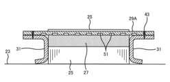
- Figure 19 shows an example of the cross-sectional structure of conductor 29A according to this modified example.
- a plurality of circumferentially extending grooves 51 are formed at a predetermined interval in the axial direction on the radially inner side of conductor 29A. Due to the plurality of grooves 51, thicker and thinner portions of conductor 29A alternate along the axial direction, resulting in a configuration in which the thickness of conductor 29A changes in the axial direction.
- the damping effect can be reduced without changing the shape of conductor insertion hole 37. In other words, it is possible to adjust the damping effect without changing the design of rotor core 25.
- the inside of the slit 35 of the conductor 29 is empty, but the inside of the slit 35 may be filled with a content.
- the slits 35 of the conductor 29 may be filled with permanent magnets 53.
- the permanent magnets 53 are configured separately from the permanent magnets 27 provided inside the rotor core 25. According to this modification, the amount of magnets in the rotor 21F can be increased, improving the motor characteristics of the permanent magnet motor 3.
- FIG. 21 for example, a structure in which an iron core member 55 is filled inside the slits 35 of the conductor 29 may be used.
- the magnet insertion holes 33 and the conductor insertion holes 37 are formed separately in the radial direction.
- the iron core member 55 may be configured integrally with the rotor core 25A, or may be configured separately from the rotor core 25A. According to this modification, the flow of magnetic flux in the rotor 21G becomes smoother, thereby improving the motor characteristics of the permanent magnet motor 3.
- connection member 31 (6-7. Variations in methods for joining conductors and connecting members)
- the conductor 29 and the coupling portion 31c of the connection member 31 are joined by laser welding, but they may be joined by a method other than laser welding.
- the joining may be performed by a welding method other than laser welding, such as spot welding.
- the joining may also be performed by applying processing pressure to a hole shape, so-called crimping.
- the joining may also be performed by plastically deforming a rivet fitting fitted into the joining portion.
- the joining may also be performed by soldering, for example.
- the joining may also be performed using a conductive adhesive or conductive double-sided tape, for example.
- the joining may also be performed by screws or bolts and nuts.
- the joining may also be performed by bending a part of the conductor 29 and a part of the connection member 31 to join them, so-called seam folding.
- the conductor 29 and the connection member 31 are described as being separate bodies, but they do not necessarily have to be separate bodies.
- the conductor 29 and the connection member 31 may be manufactured as a single body, for example by molding them as a single body using a copper die casting method.
Landscapes
- Engineering & Computer Science (AREA)
- Power Engineering (AREA)
- Permanent Field Magnets Of Synchronous Machinery (AREA)
Abstract
Description
図1に、実施形態に係るモータ制御システム1の全体構成の一例を示す。図1に示すように、モータ制御システム1は、複数の永久磁石モータ3と、複数の永久磁石モータ3を駆動するための1台のインバータ5と、を有する。永久磁石モータ3の台数は複数であれば特に限定されるものではない。図1では、例えば3台である場合を図示している。
図2~図4に、永久磁石モータ3の構成の一例を示す。図2は永久磁石モータ3の構成の一例を表す軸方向から見た側面図であり、フレーム及び固定子を簡略化して一点鎖線で示している。図3は永久磁石モータ3の回転子の構造の一例を表す斜視図であり、図4は回転子の構造の一例を表す分解斜視図である。
図5~図12に、回転子21の組立工程の一例を示す。回転子21の組立工程は、永久磁石モータ3の製造方法の一例である。
図13に、接続部材31の固定構造の一例を示す。
以上説明したように、本実施形態のモータ制御システム1が有する永久磁石モータ3は、回転子鉄心25の内部に設けられた複数の永久磁石27と、回転子鉄心25の内部において永久磁石27よりも径方向外側に形成された導体挿入穴37と、導体挿入穴37に挿入された導体29と、を有する。これにより、負荷変動による永久磁石モータ3間の負荷の不均衡などの外乱が発生した場合には、導体29に渦電流が流れ、図示しない固定子巻線によって発生する磁束と導体29の渦電流との相互作用により、誘導トルクによるダンパ効果を発生させることができる。その結果、永久磁石モータ3の制御が不安定となる乱調を抑制して、システムの安定化を図ることができる。特に、導体29が永久磁石27よりも径方向外側に配置されることで、負荷変動時に渦電流の発生が促進され、乱調抑制効果を高めることができる。また、始動電流による永久磁石減磁作用を渦電流による反作用磁束により弱めることができるので、永久磁石27の減磁を低減できる。また、導体29が回転子鉄心25内に埋め込まれる構造のため、例えばインバータ駆動時の時間高調波の影響を低減できる。その結果、導体29の発熱による永久磁石モータ3の温度上昇、永久磁石27の減磁、導体29の渦電流損を低減できる。
開示の実施形態は、上記に限られるものではなく、その趣旨及び技術的思想を逸脱しない範囲内で種々の変形が可能である。以下、そのような変形例を説明する。
上記実施形態では、磁石挿入穴33と導体挿入穴37とが連通し、1つのつながった穴として形成されている場合について説明したが、磁石挿入穴33と導体挿入穴37とを分離してもよい。
上記実施形態では、導体29を径方向に1層のみ配置する場合について説明したが、導体29を径方向に複数層配置してもよい。
上記実施形態では、永久磁石27の軸方向から見た形状が、外周側が膨らみ内周側が凹んだ略円弧形状である場合について説明したが、永久磁石27の形状を上記以外の形状としてもよい。
上記実施形態では設けなかったが、回転子鉄心の外周に円筒部材を設置してもよい。
上記実施形態では導体29の厚みを一定としたが、例えば導体29の厚みを軸方向で変化させてもよい。
上記実施形態では導体29のスリット35の内部を空としたが、スリット35の内部に内容物を充填した構造としてもよい。
上記実施形態では、導体29と接続部材31の連結部31cとをレーザ溶接で接合する構成としたが、レーザ溶接以外の手法で接合してもよい。
上記実施形態では、導体29と接続部材31とが別体である場合について説明したが、必ずしも別体である必要はなく、例えば銅ダイキャスト製法などにより一体成形することで、導体29と接続部材31とを一体的に製造してもよい。
3 永久磁石モータ
5 インバータ
21 回転子
21C 回転子
21D 回転子
21E 回転子
21F 回転子
21G 回転子
23 シャフト
25 回転子鉄心
25A 回転子鉄心
25C 回転子鉄心
27 永久磁石
27C 永久磁石
27D 永久磁石
29 導体
29A 導体
29C 導体
29D 導体
31 接続部材
31a 第1接触部
31b 第2接触部
31c 連結部
32 調整穴
33 磁石挿入穴
33C 磁石挿入穴
33D 磁石挿入穴
35 スリット
37 導体挿入穴
37A 導体挿入穴
37B 導体挿入穴
37C 導体挿入穴
37D 導体挿入穴
39 開口部
43 接合部
45 穴部
47 穴部
AX 回転軸心
Claims (13)
- 複数の永久磁石モータと、
前記複数の永久磁石モータを駆動するための1つのインバータと、
を有し、
前記永久磁石モータは、
回転可能に支持された回転子鉄心と、
前記回転子鉄心の内部に設けられた複数の永久磁石と、
前記回転子鉄心の内部において前記永久磁石よりも径方向における外側に形成された導体挿入穴と、
前記導体挿入穴に挿入された導体と、
を有する、モータ制御システム。 - 前記導体挿入穴は、
前記複数の永久磁石により前記回転子鉄心に形成される複数の磁極の各磁極において、1つの前記磁極に対して1つ配置されるように形成されている、
請求項1に記載のモータ制御システム。 - 前記永久磁石モータは、
前記回転子鉄心の内部において前記導体挿入穴よりも前記径方向における内側に形成され、前記永久磁石が挿入される磁石挿入穴を有し、
前記複数の磁極の各磁極において、前記磁石挿入穴と前記導体挿入穴とは連通している、
請求項2に記載のモータ制御システム。 - 前記導体は、
前記回転子鉄心の回転方向における寸法が前記径方向の寸法よりも大きな板状に形成されている、
請求項3に記載のモータ制御システム。 - 前記導体には、
当該導体を前記径方向に貫通し、前記径方向に垂直な方向に細長く延びる1又は複数のスリットが形成されている、
請求項4に記載のモータ制御システム。 - 前記導体は、
前記複数の磁極の各磁極において、前記径方向に複数層となるように配置されている、
請求項5に記載のモータ制御システム。 - 前記永久磁石モータは、
前記回転子鉄心の軸方向両側に配置され、複数の前記導体を接続するリング状の接続部材を有する、
請求項1乃至6のいずれか1項に記載のモータ制御システム。 - 前記接続部材は、
前記回転子鉄心の前記軸方向の端部に接触する、
請求項7に記載のモータ制御システム。 - 前記接続部材は、
前記回転子鉄心が固定されたシャフトの外周面に接触する、
請求項7に記載のモータ制御システム。 - 前記接続部材は、
前記回転子鉄心の前記軸方向の端部に接触する第1接触部と、
前記第1接触部の前記径方向における内側が屈曲されて形成され、前記回転子鉄心が固定されたシャフトの外周面に接触する第2接触部と、
前記第1接触部の前記径方向における外側が屈曲されて形成され、複数の前記導体に連結される連結部と、
を有する、請求項7に記載のモータ制御システム。 - 前記回転子鉄心には、
回転方向の重量バランスを調整するための調整穴が前記回転方向の複数個所に形成されており、
前記第1接触部には、
前記調整穴に対応する位置に開口部が形成されている、
請求項10に記載のモータ制御システム。 - 回転可能に支持された回転子鉄心と、
前記回転子鉄心の内部に設けられた複数の永久磁石と、
前記複数の永久磁石により前記回転子鉄心に形成される複数の磁極の各磁極において、前記回転子鉄心の内部において前記永久磁石よりも径方向における外側に形成され、1つの前記磁極に対して1つ配置された導体挿入穴と、
前記導体挿入穴に挿入された導体と、
を有する、永久磁石モータ。 - シャフトに回転子鉄心を固定することと、
前記回転子鉄心の内部に形成された複数の導体挿入穴に導体を挿入することと、
前記回転子鉄心の内部において前記導体挿入穴よりも径方向における内側に形成された複数の磁石挿入穴に永久磁石を挿入することと、
複数の前記導体の軸方向一方側の端部及び軸方向他方側の端部を、リング状の接続部材により接続することと、
を有する、永久磁石モータの製造方法。
Priority Applications (2)
| Application Number | Priority Date | Filing Date | Title |
|---|---|---|---|
| CN202380081191.6A CN120266370A (zh) | 2023-01-26 | 2023-12-12 | 马达控制系统、永磁马达、永磁马达的制造方法 |
| JP2024572875A JPWO2024157633A1 (ja) | 2023-01-26 | 2023-12-12 |
Applications Claiming Priority (2)
| Application Number | Priority Date | Filing Date | Title |
|---|---|---|---|
| JP2023-010371 | 2023-01-26 | ||
| JP2023010371 | 2023-01-26 |
Publications (1)
| Publication Number | Publication Date |
|---|---|
| WO2024157633A1 true WO2024157633A1 (ja) | 2024-08-02 |
Family
ID=91970333
Family Applications (1)
| Application Number | Title | Priority Date | Filing Date |
|---|---|---|---|
| PCT/JP2023/044534 Ceased WO2024157633A1 (ja) | 2023-01-26 | 2023-12-12 | モータ制御システム、永久磁石モータ、永久磁石モータの製造方法 |
Country Status (3)
| Country | Link |
|---|---|
| JP (1) | JPWO2024157633A1 (ja) |
| CN (1) | CN120266370A (ja) |
| WO (1) | WO2024157633A1 (ja) |
Citations (8)
| Publication number | Priority date | Publication date | Assignee | Title |
|---|---|---|---|---|
| JPH04112652A (ja) * | 1990-08-30 | 1992-04-14 | Aichi Emerson Electric Co Ltd | 圧縮機用電動機の回転子 |
| JP2001190095A (ja) * | 1999-10-25 | 2001-07-10 | Murata Mach Ltd | モータ駆動システム |
| JP2003047183A (ja) * | 2001-06-14 | 2003-02-14 | Lg Electronics Inc | 単相ラインスタート永久磁石同期電動機 |
| JP2003259579A (ja) * | 2002-02-28 | 2003-09-12 | Tma Electric Corp | 永久磁石同期回転電機の回転子およびその製造方法 |
| JP2005102483A (ja) * | 2003-08-18 | 2005-04-14 | Asmo Co Ltd | 誘導電動機の回転子及び誘導電動機 |
| KR20070104977A (ko) * | 2006-04-24 | 2007-10-30 | 주식회사 대우일렉트로닉스 | Lspm 동기모터의 로터 |
| JP2017050918A (ja) * | 2015-08-31 | 2017-03-09 | 株式会社東芝 | 同期リラクタンスモータ |
| CN111614181A (zh) * | 2020-06-24 | 2020-09-01 | 珠海格力电器股份有限公司 | 自起动混合励磁的永磁辅助磁阻电机的转子结构、电机 |
-
2023
- 2023-12-12 CN CN202380081191.6A patent/CN120266370A/zh active Pending
- 2023-12-12 JP JP2024572875A patent/JPWO2024157633A1/ja active Pending
- 2023-12-12 WO PCT/JP2023/044534 patent/WO2024157633A1/ja not_active Ceased
Patent Citations (8)
| Publication number | Priority date | Publication date | Assignee | Title |
|---|---|---|---|---|
| JPH04112652A (ja) * | 1990-08-30 | 1992-04-14 | Aichi Emerson Electric Co Ltd | 圧縮機用電動機の回転子 |
| JP2001190095A (ja) * | 1999-10-25 | 2001-07-10 | Murata Mach Ltd | モータ駆動システム |
| JP2003047183A (ja) * | 2001-06-14 | 2003-02-14 | Lg Electronics Inc | 単相ラインスタート永久磁石同期電動機 |
| JP2003259579A (ja) * | 2002-02-28 | 2003-09-12 | Tma Electric Corp | 永久磁石同期回転電機の回転子およびその製造方法 |
| JP2005102483A (ja) * | 2003-08-18 | 2005-04-14 | Asmo Co Ltd | 誘導電動機の回転子及び誘導電動機 |
| KR20070104977A (ko) * | 2006-04-24 | 2007-10-30 | 주식회사 대우일렉트로닉스 | Lspm 동기모터의 로터 |
| JP2017050918A (ja) * | 2015-08-31 | 2017-03-09 | 株式会社東芝 | 同期リラクタンスモータ |
| CN111614181A (zh) * | 2020-06-24 | 2020-09-01 | 珠海格力电器股份有限公司 | 自起动混合励磁的永磁辅助磁阻电机的转子结构、电机 |
Also Published As
| Publication number | Publication date |
|---|---|
| JPWO2024157633A1 (ja) | 2024-08-02 |
| CN120266370A (zh) | 2025-07-04 |
Similar Documents
| Publication | Publication Date | Title |
|---|---|---|
| JP7283091B2 (ja) | 界磁巻線型回転電機 | |
| US8760027B2 (en) | Stator | |
| US12034333B2 (en) | Stator and motor comprising said stator | |
| JP4535146B2 (ja) | コイルの固定部材及び回転電機 | |
| CN103201931A (zh) | 旋转电机 | |
| JP5267751B1 (ja) | 回転電機 | |
| JP2009100531A (ja) | インナーロータブラシレスモータ及びその製造方法 | |
| JP4665454B2 (ja) | モータ | |
| US12149140B2 (en) | Electric motor assembly | |
| CN117879197B (zh) | 定子磁芯、定子总成、直线电机、悬架系统和车辆 | |
| JP7166207B2 (ja) | 回転電機およびその製造方法 | |
| JP2017005873A (ja) | コアおよび回転電機 | |
| CN102742124B (zh) | 定子以及旋转电机 | |
| JP6069695B2 (ja) | モータ用ロータ | |
| WO2024157633A1 (ja) | モータ制御システム、永久磁石モータ、永久磁石モータの製造方法 | |
| JP6824334B2 (ja) | ステータ及び電動機 | |
| JP2012244839A (ja) | 回転電機のステータ | |
| JP2020014368A (ja) | ブラシレスモータ及びブラシレスモータの製造方法 | |
| WO2023032642A1 (ja) | 回転電機 | |
| JP2012016112A (ja) | 車両用回転電機のエンドプレート | |
| US20220181926A1 (en) | Motor | |
| CN222531515U (zh) | 一种三相爪极步进电机 | |
| JP7852525B2 (ja) | モータの支持構造 | |
| LU507636B1 (en) | Motor Stator Core | |
| CN113557651B (zh) | 转子以及具备转子的电动机 |
Legal Events
| Date | Code | Title | Description |
|---|---|---|---|
| 121 | Ep: the epo has been informed by wipo that ep was designated in this application |
Ref document number: 23918588 Country of ref document: EP Kind code of ref document: A1 |
|
| WWE | Wipo information: entry into national phase |
Ref document number: 2024572875 Country of ref document: JP |
|
| WWE | Wipo information: entry into national phase |
Ref document number: 202380081191.6 Country of ref document: CN |
|
| WWP | Wipo information: published in national office |
Ref document number: 202380081191.6 Country of ref document: CN |
|
| NENP | Non-entry into the national phase |
Ref country code: DE |
|
| 122 | Ep: pct application non-entry in european phase |
Ref document number: 23918588 Country of ref document: EP Kind code of ref document: A1 |