WO2024157329A1 - 内燃機関の制御装置 - Google Patents
内燃機関の制御装置 Download PDFInfo
- Publication number
- WO2024157329A1 WO2024157329A1 PCT/JP2023/001946 JP2023001946W WO2024157329A1 WO 2024157329 A1 WO2024157329 A1 WO 2024157329A1 JP 2023001946 W JP2023001946 W JP 2023001946W WO 2024157329 A1 WO2024157329 A1 WO 2024157329A1
- Authority
- WO
- WIPO (PCT)
- Prior art keywords
- parameter
- value
- signal value
- internal combustion
- combustion engine
- Prior art date
- Legal status (The legal status is an assumption and is not a legal conclusion. Google has not performed a legal analysis and makes no representation as to the accuracy of the status listed.)
- Ceased
Links
Images
Classifications
-
- F—MECHANICAL ENGINEERING; LIGHTING; HEATING; WEAPONS; BLASTING
- F02—COMBUSTION ENGINES; HOT-GAS OR COMBUSTION-PRODUCT ENGINE PLANTS
- F02D—CONTROLLING COMBUSTION ENGINES
- F02D41/00—Electrical control of supply of combustible mixture or its constituents
- F02D41/02—Circuit arrangements for generating control signals
- F02D41/14—Introducing closed-loop corrections
- F02D41/1438—Introducing closed-loop corrections using means for determining characteristics of the combustion gases; Sensors therefor
- F02D41/1444—Introducing closed-loop corrections using means for determining characteristics of the combustion gases; Sensors therefor characterised by the characteristics of the combustion gases
- F02D41/1454—Introducing closed-loop corrections using means for determining characteristics of the combustion gases; Sensors therefor characterised by the characteristics of the combustion gases the characteristics being an oxygen content or concentration or the air-fuel ratio
- F02D41/1455—Introducing closed-loop corrections using means for determining characteristics of the combustion gases; Sensors therefor characterised by the characteristics of the combustion gases the characteristics being an oxygen content or concentration or the air-fuel ratio with sensor resistivity varying with oxygen concentration
-
- F—MECHANICAL ENGINEERING; LIGHTING; HEATING; WEAPONS; BLASTING
- F02—COMBUSTION ENGINES; HOT-GAS OR COMBUSTION-PRODUCT ENGINE PLANTS
- F02D—CONTROLLING COMBUSTION ENGINES
- F02D41/00—Electrical control of supply of combustible mixture or its constituents
- F02D41/02—Circuit arrangements for generating control signals
- F02D41/14—Introducing closed-loop corrections
- F02D41/1438—Introducing closed-loop corrections using means for determining characteristics of the combustion gases; Sensors therefor
- F02D41/1444—Introducing closed-loop corrections using means for determining characteristics of the combustion gases; Sensors therefor characterised by the characteristics of the combustion gases
- F02D41/1454—Introducing closed-loop corrections using means for determining characteristics of the combustion gases; Sensors therefor characterised by the characteristics of the combustion gases the characteristics being an oxygen content or concentration or the air-fuel ratio
- F02D41/1456—Introducing closed-loop corrections using means for determining characteristics of the combustion gases; Sensors therefor characterised by the characteristics of the combustion gases the characteristics being an oxygen content or concentration or the air-fuel ratio with sensor output signal being linear or quasi-linear with the concentration of oxygen
-
- F—MECHANICAL ENGINEERING; LIGHTING; HEATING; WEAPONS; BLASTING
- F02—COMBUSTION ENGINES; HOT-GAS OR COMBUSTION-PRODUCT ENGINE PLANTS
- F02D—CONTROLLING COMBUSTION ENGINES
- F02D41/00—Electrical control of supply of combustible mixture or its constituents
- F02D41/02—Circuit arrangements for generating control signals
- F02D41/14—Introducing closed-loop corrections
- F02D41/1438—Introducing closed-loop corrections using means for determining characteristics of the combustion gases; Sensors therefor
- F02D41/1493—Details
- F02D41/1494—Control of sensor heater
Definitions
- the present invention relates to a control device for an internal combustion engine that controls the internal combustion engine based on parameters obtained from the oxygen concentration in the exhaust gas.
- control device for an internal combustion engine that includes an oxygen sensor having a detection unit that is disposed in contact with the exhaust gas of an internal combustion engine equipped with a fuel injection valve and detects the oxygen concentration in the exhaust gas, and that controls the internal combustion engine based on the excess air ratio ⁇ , which is a parameter obtained based on the detection value from the detection unit (see, for example, Patent Document 1).
- the device of Patent Document 1 includes a temperature detection unit that detects the temperature of a detection unit having a predetermined temperature characteristic, and an excess ratio calculation unit that calculates the exhaust air excess ratio ⁇ using data obtained by linearly converting the detection value to the air excess ratio while compensating for the temperature characteristic, based on the detection value and temperature of the detection unit.
- the detection unit (sensor element) uses a titania-type sensor element, which is a resistance-type oxygen sensor whose resistance value changes depending on the oxygen concentration.
- the excess ratio calculation unit includes a limit threshold setting unit that sets a conversion limit threshold for the linearization conversion, and a data map that associates the temperature and detection value of the oxygen sensor detection unit with the exhaust air excess ratio ⁇ .
- the linearized converted data is obtained using this data map, and when the detection value or the linearized converted data is equal to or less than the conversion limit threshold, the linearized converted data is regarded as the exhaust air excess ratio ⁇ .
- the excess ratio calculation unit regards the alternative value R calculated based on the ratio between the fuel injection execution time and the torque value as the air excess ratio ⁇ , instead of the linearized converted data.
- Patent Document 1 uses a sensor element whose resistance value changes significantly depending on the oxygen partial pressure, so when setting the data map, it is difficult to perform tests that fix the exhaust temperature and oxygen sensor output, and the amount of work required for trial and error using the actual device is burdensome.
- the object of the present invention is to provide a control device for an internal combustion engine that has a means for calculating the excess air ratio with high accuracy and that allows easy setting of tables, etc.
- the control device for an internal combustion engine of the present invention comprises: 1.
- a control device for an internal combustion engine including a parameter detection unit that detects a parameter obtained based on an oxygen concentration in exhaust gas from an internal combustion engine including a fuel injection valve, based on a signal value that changes in one direction as the parameter increases,
- the parameter detection unit when a third signal value between a first signal value corresponding to a first parameter as the parameter and a second signal value corresponding to a second parameter as the parameter larger than the first parameter is input as the signal value, a third parameter is detected based on the first signal value, the first parameter, the second signal value, the second parameter, and the third signal value, the third parameter being the parameter corresponding to the third signal value;
- the third parameter does not change linearly with respect to the change in the signal value, but changes along a curve with an increasing rate of change.
- parameters include the excess air ratio and the air-fuel ratio.
- the third parameter can be detected with good accuracy.
- the third parameter corresponding to the third signal value in the interval between the first signal value and the second signal value can be determined with good accuracy by simple processing set with few man-hours.
- the third parameter corresponding to the third signal value can be found by a process set up with few steps by using the method of calculating the replacement value R disclosed in Patent Document 1 or the method of performing linear interpolation.
- a control device for an internal combustion engine equipped with a parameter detection unit that can calculate a third parameter (excess air ratio or air-fuel ratio) using only an easily settable two-dimensional table and a simple calculation formula, without the need to set up a three-dimensional data map, which is complicated and labor-intensive.
- the second parameter may be smaller than the parameter corresponding to the theoretical air-fuel ratio of the internal combustion engine.
- the first signal value corresponding to the first parameter and the second signal value corresponding to the second parameter can be appropriately set so that the third parameter has a characteristic of changing more sensitively to changes in the third signal value as the third signal value approaches the first signal value.
- a detection unit that detects the oxygen concentration in the exhaust gas may be provided, and the signal value may be smaller as the temperature of the detection unit increases when the parameter is constant.
- the third parameter can be calculated using only a two-dimensional table that is easy to set up and a simple formula, without the need to set up a three-dimensional data map, which is complicated and requires a lot of work.
- a detection unit that detects the oxygen concentration in the exhaust gas may be provided, and the parameter may be such that, when the signal value is constant, the parameter increases as the temperature of the detection unit increases.
- the third parameter can be calculated using only a two-dimensional table that is easy to set up and a simple formula, without the need to set up a three-dimensional data map, which is complicated and requires a lot of work.
- a detection unit that detects the oxygen concentration in the exhaust gas, a voltage calculation unit that calculates a voltage value indicating the oxygen concentration based on the detection value from the detection unit, and a temperature calculation unit that calculates a temperature value indicating the temperature of the detection unit are provided, and the signal value is a voltage value calculated by the voltage calculation unit, and the one direction may be a direction in which the voltage value increases.
- the third parameter can be calculated using only an easily set up two-dimensional table and a simple formula, without the need to set up a three-dimensional data map, which is complicated and labor-intensive.
- the third parameter PARAM3 corresponding to the third signal value VHGM between the first signal value VHGR and the second signal value VHGL can be detected with good accuracy.
- FIG. 1 is a schematic diagram showing a configuration of a main part of an internal combustion engine equipped with a control device according to an embodiment of the present invention
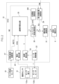
- 2 is a block diagram showing a main configuration of an ECU of the internal combustion engine of FIG. 1
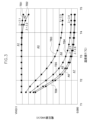
- 3 is a diagram showing divided regions A1 to A7 to which respective calculation methods are applied when an excess ratio calculation unit in the ECU in FIG. 2 calculates an air excess ratio ⁇ .
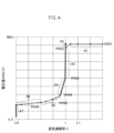
- FIG. This figure shows the characteristics ( ⁇ -voltage characteristics (T ⁇ )) of the voltage value VHG versus the air excess ratio ⁇ when the temperature value T input to the excess ratio calculation unit in Figure 3 is a temperature T ⁇ that is higher than T2 and lower than T3, for the areas A1 to A7 in Figure 3.
- T ⁇ ⁇ -voltage characteristics
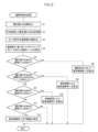
- FIG. 3 is a flowchart showing an excess rate calculation process in an excess rate calculation unit of the ECU of FIG. 2 .
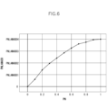
- 6 is a diagram showing an example of a table that associates a coefficient PN and a ⁇ addition value PNLAMADD used in the excess rate calculation process of FIG. 5 .
- FIG. 5 is a diagram showing an example of a table that associates a coefficient PN and a ⁇ addition value PNLAMADD used in the excess rate calculation process of FIG. 5 .
- Figure 1 shows the configuration of the main parts of a four-stroke internal combustion engine equipped with an internal combustion engine control device according to one embodiment of the present invention.
- the engine body 1 of this internal combustion engine is equipped with an intake pipe 2 provided at an intake port, and a throttle valve 3 provided within the intake pipe 2 to adjust the amount of intake air supplied to the intake port from an air cleaner 4 according to the opening degree.
- the throttle valve 3 is provided with a throttle sensor 5 that detects the opening of the throttle valve 3.
- a fuel injection valve 6 that injects fuel is provided near the intake port of the intake pipe 2. Fuel is pumped from a fuel tank (not shown) to the fuel injection valve 6 by a fuel pump.
- the intake pipe 2 is provided with an intake pressure sensor 7 that detects the intake pressure in the intake pipe 2 and an intake air temperature sensor 8 that detects the temperature of the intake air in the intake pipe 2.
- a catalyst 11 that reduces unburned components in the exhaust of the exhaust pipe 10 and an oxygen sensor 12 that detects the oxygen concentration in the exhaust are provided.
- An ignition plug 13 connected to an ignition device 14 is fixed to the engine body 1.
- an ECU (electronic control unit) 15 issues an ignition timing command to the ignition device 14, a spark discharge occurs in the cylinder combustion chamber of the engine body 1.
- the ECU 15 receives analog voltages indicating the detection values of the throttle sensor 5, intake pressure sensor 7, intake air temperature sensor 8, oxygen sensor 12, coolant temperature sensor 17, and atmospheric pressure sensor 20 that detects atmospheric pressure.
- the fuel injection valve 6 is also connected to the ECU 15.
- the ECU 15 also receives a signal indicating the rotational angle position of the crankshaft 18 from a crank angle sensor 19. That is, the crank angle sensor 19 magnetically or optically detects multiple protrusions provided at predetermined angles (e.g., 15 degrees) on the outer periphery of a rotor 19a that rotates in conjunction with the crankshaft 18, using a pickup 19b located near the outer periphery of the rotor 19a, and generates a pulse (crank signal) from the pickup 19b every time the crankshaft 18 rotates by the predetermined angle.
- predetermined angles e.g. 15 degrees
- crank angle sensor 19 outputs a signal indicating the reference angle to the ECU 15 each time the piston 9 reaches top dead center or each time the crankshaft 18 rotates 360 degrees.
- Figure 2 shows the main components of the ECU 15.
- the oxygen sensor 12 which supplies the ECU 15 with a detection signal of the oxygen concentration in the exhaust gas, includes a sensor element 12a that is disposed in contact with the exhaust gas from the internal combustion engine and serves as a detector for detecting the oxygen concentration in the exhaust gas, and a sensor heater 12b that is adjacent to the sensor element 12a and heats the sensor element 12a.
- the sensor element 12a has temperature characteristics in which the detection value changes according to the temperature of the sensor element 12a.
- a titania-type sensor element which is a resistive oxygen sensor whose resistance value changes according to the oxygen concentration, is used as the sensor element 12a.
- the ECU 15 includes a heater controller 22 that controls the sensor heater 12b, a temperature calculation unit 23 that calculates a temperature value T that indicates the temperature of the sensor element 12a, and a voltage calculation unit 24 that converts the output signal of the sensor element 12a into a voltage value VHG that indicates the oxygen concentration in the exhaust gas.
- the heater controller 22 controls the temperature of the sensor heater 12b by controlling the amount of current I supplied to the sensor heater 12b from a power source (storage battery) (not shown) using pulse width modulation (PWM) control by the ECU 15.
- the temperature calculation unit 23 calculates the temperature value T by, for example, reading the resistance value of the sensor heater 12b using the ECU 15.
- the ECU 15 also includes a rotation speed calculation unit 27 that calculates the rotation speed NE and angular speed NETC of the internal combustion engine based on the detection results of the crank angle sensor 19, and an excess air ratio calculation unit 25 that calculates an excess air ratio ⁇ based on the temperature value T from the temperature calculation unit 23, the voltage value VHG from the voltage calculation unit 24, and the angular speed NETC from the rotation speed calculation unit 27.
- the ECU 15 further includes a target value calculation unit 28 that calculates the target excess air ratio ⁇ cmd based on an estimated value of the amount of oxygen stored in the catalyst 11, a basic injection amount calculation unit 29 that calculates a basic injection amount BJ based on the rotation speed NE from the rotation speed calculation unit 27 and the pressure PM in the intake pipe 2 from the intake pressure sensor 7, a feedback coefficient calculation unit 30 that determines a feedback coefficient k for correcting the basic fuel injection amount BJ calculated by the basic injection amount calculation unit 29 so that the excess air ratio ⁇ calculated by the excess ratio calculation unit 25 matches the target excess air ratio ⁇ cmd, and an injection amount calculation unit 31 that calculates the injection amount Ti based on the feedback coefficient k and the basic injection amount BJ and operates the fuel injection valve 6.
- a target value calculation unit 28 that calculates the target excess air ratio ⁇ cmd based on an estimated value of the amount of oxygen stored in the catalyst 11
- a basic injection amount calculation unit 29 that calculates a basic injection amount BJ based on the rotation speed
- PID control is performed based on a comparison between the excess air ratio ⁇ and the target excess air ratio ⁇ cmd, and the feedback coefficient k is calculated.
- the fuel injection valve 6 is opened for a corresponding time, and thus an amount of fuel according to the feedback coefficient k of the PID control based on a comparison between the excess air ratio ⁇ and the target excess air ratio ⁇ cmd is injected into the cylinder combustion chamber of the engine body 1.
- FIG. 3 shows seven divided regions to which each calculation method is applied when the excess ratio calculation unit 25, which serves as a parameter detection unit, calculates the air excess ratio ⁇ .
- the seven regions A1 to A7 are obtained by dividing the region consisting of the horizontal axis scale for the temperature value T calculated by the temperature calculation unit 23 and the vertical axis scale for the voltage value VHG calculated by the voltage calculation unit 24, by six graph curves indicating six predetermined air excess ratios ⁇ .
- the six predetermined air excess factors ⁇ may be, for example, ⁇ 1, ⁇ 2, ⁇ 3, ⁇ 4, ⁇ 5, and ⁇ 6.
- the six graph curves showing each air excess factor ⁇ constitute six lookup tables that associate the temperature value T with the voltage value VHG for each air excess factor ⁇ , that is, lookup tables TB1 to TB6 from the lean side.
- the voltage value VHG as a signal value has a characteristic that, when the air excess ratio ⁇ as a parameter is constant, the higher the temperature value T of the sensor element 12a as the detection unit, the smaller the voltage value VHG as a signal value becomes. Also, when the voltage value VHG is constant, the higher the temperature value T, the larger the air excess ratio ⁇ becomes.
- FIG. 4 shows the characteristics ( ⁇ -voltage characteristics (T ⁇ )) of the voltage value VHG versus the air excess factor ⁇ when the temperature value T is a temperature T ⁇ higher than T2 and lower than T3, corresponding to seven regions A1 to A7 divided from the lean side by the six graph curves (six air excess factors ⁇ ). Note that in FIG. 4, VHG11>0.
- the excess factor calculation unit 25 calculates the air excess factor ⁇ corresponding to the voltage value VHG input from the voltage calculation unit 24 in a method corresponding to the corresponding region depending on which of the regions A1 to A7 shown in FIG. 4 the voltage value VHG falls into.
- FIG. 5 shows the excess ratio calculation process for calculating the air excess ratio ⁇ in the excess ratio calculation unit 25. Note that the control by the ECU 15, including this excess ratio calculation process, is executed in synchronization with the stroke of the internal combustion engine, based on a pulse signal indicating the rotational angle position of the crankshaft 18 from the crank angle sensor 19.
- step S1 the voltage value VHG is read from the voltage calculation unit 24.
- step S2 the voltage value VHGMA is obtained by performing a moving average process on the read voltage value VHG.
- step S3 the temperature value T of the sensor element 12a of the oxygen sensor 12 is read from the temperature calculation unit 23.
- step S4 based on the read temperature value T, voltage values VHG1 to VHG6 are obtained from each of the lookup tables TB1 to TB6 corresponding to the excess air factor ⁇ indicated by the six graph curves described above.
- the voltage values VHG1 to VHG6 indicate the boundaries of the seven areas A1 to A7 described above at the read temperature value T.
- step S5 the voltage values VHG1 to VHG6 are compared with the voltage value VHGMA calculated in step S2 to determine whether or not the voltage value VHGMA corresponds to region A1 (VHGMA ⁇ VHG1). If it is determined that the voltage value VHGMA corresponds to region A1, then in step S6, the excess air factor ⁇ is calculated according to the operating conditions of the internal combustion engine. Specifically, the method disclosed in the above-mentioned Patent Document 1 can be used.
- the torque value calculated based on the crank angular velocity NETC of the internal combustion engine is TQ1
- the air excess ratio separating region A1 from region A2 is ⁇ b
- the injection amount when the air excess ratio ⁇ reaches a value corresponding to region A1 is Ti2 and the torque is TQ2
- the air excess ratio ⁇ is calculated by the following formula (1).
- ⁇ ((Ti1 ⁇ Ti2) ⁇ (TQ1 ⁇ TQ2)) ⁇ b (1)
- step S5 If it is determined in step S5 that the voltage value VHGMA does not correspond to region A1 (VHGMA ⁇ VHG1), it is determined in step S7 whether the voltage value VHGMA corresponds to any of regions A2, A3, A4, or A6. If it is determined that the voltage value VHGMA corresponds to any of regions A2, A3, A4, or A6, the excess air factor ⁇ corresponding to the voltage value VHGMA is calculated by linear interpolation in step S8.
- the lean side value of the air excess factor ⁇ dividing the area A2, A3, A4 or A6 corresponding to the voltage value VHGMA is defined as the lean side excess factor LAML
- the rich side value is defined as the rich side excess factor LAMR
- the corresponding voltage value in the lean side lookup table is defined as the lean side voltage value VHGL
- the rich side voltage value is defined as the rich side voltage value VHGR.
- step S9 it is determined whether the voltage value VHGMA corresponds to area A5 (VHG4>VHGMA>VHG5). If it is determined that the voltage value VHGMA corresponds to area A5, then in step S10 the excess air factor ⁇ corresponding to the voltage value VHGMA is calculated by curve interpolation, and the excess air factor calculation process ends.
- FIG. 6 shows an example of a table that can be used to calculate the air excess factor ⁇ by curve interpolation in step S10. This table associates the search ratio coefficient PN with the ⁇ addition value PNLAMADD. However, in FIG. 6, 0 ⁇ PNLAMADD1 ⁇ PNLAMADD2 ⁇ PNLAMADD3 ⁇ PNLAMADD4.
- the calculation of the air excess ratio ⁇ in step S10 can be performed by obtaining a ⁇ addition value PNLAMADD corresponding to the coefficient PN calculated by the following equation (3) from the table in FIG. 6, setting the values of the air excess ratio ⁇ at the lean side boundary and the rich side boundary of region A5 as the lean side boundary excess ratio LAML and the rich side boundary excess ratio LAMR, respectively, and using the following equation (4).
- PN (VHGMA-VHG5) ⁇ (VHG4-VHG5) (3)
- ⁇ [(LAML-LAMR) ⁇ PNLAMADD]+LAMR (4)
- step S9 If it is determined in step S9 that the voltage value VHGMA does not correspond to region A5, then in step S11 it is determined whether the voltage value VHGMA corresponds to region A7 (VHGMA ⁇ VHG6), and if it is determined that it does not correspond to region A7, the excess ratio calculation process ends. If it is determined that it corresponds to region A7, then in step S12 a predetermined lower limit value for the air excess ratio, for example the above-mentioned ⁇ 6, is set as the air excess ratio ⁇ , and the excess ratio calculation process ends.
- a predetermined lower limit value for the air excess ratio for example the above-mentioned ⁇ 6, is set as the air excess ratio ⁇ , and the excess ratio calculation process ends.
- the temperature value T and voltage value VHG of the sensor element 12a are set as the horizontal and vertical axes, and six graph curves showing six air excess ratios ⁇ are plotted on these, dividing the region into seven regions A1 to A7 from the lean side.
- the air excess ratio ⁇ of region A1 is obtained using the above-mentioned formula (1)
- regions A2, A3, A4, and A6 are obtained by interpolation
- region A5 is obtained using the table in FIG. 6 and the above-mentioned formulas (3) and (4)
- the air excess ratio ⁇ of region A7 is set to a predetermined value, thereby obtaining the air excess ratio ⁇ of each region.
- the air excess factor ⁇ when the voltage value VHGMA corresponds to region A5 can be calculated with good accuracy by curve approximation using the table in FIG. 6 and the above-mentioned equations (3) and (4). Therefore, the air excess factor ⁇ when the voltage value VHGMA corresponds to region A5 can also be obtained without the need to use a complicated three-dimensional map representing the temperature value T of the sensor element 12a, the voltage value VHG, and the air excess factor ⁇ .
- the present invention is not limited to this.
Landscapes
- Engineering & Computer Science (AREA)
- Chemical & Material Sciences (AREA)
- Combustion & Propulsion (AREA)
- Mechanical Engineering (AREA)
- General Engineering & Computer Science (AREA)
- Electrical Control Of Air Or Fuel Supplied To Internal-Combustion Engine (AREA)
Abstract
Description
燃料噴射弁を備える内燃機関の排気中の酸素濃度に基づいて得られるパラメータが大きくなるにつれて一方向に変化する信号値に基づき、前記パラメータを検出するパラメータ検出部を備える内燃機関の制御装置において、
前記パラメータ検出部は、
前記信号値として、前記パラメータとしての第1パラメータに対応する第1信号値と前記第1パラメータより大きい前記パラメータとしての第2パラメータに対応する第2信号値との間の第3信号値が入力されたとき、
前記第1信号値と、前記第1パラメータと、前記第2信号値と、前記第2パラメータと、前記第3信号値とに基づき、前記第3信号値に対応する前記パラメータである第3パラメータを検出するものであり、
前記第3信号値が前記第1信号値に近いほど、前記第3信号値の変化に対して前記第3パラメータは敏感に変化することを特徴とする。
PN=(VHGM-VHGR)÷(VHGL-VHGR)
で求められる係数PNと加算値PNLAMADDとを対応付けたテーブルから、入力された前記第3信号値についての係数PNに対応する加算値PNLAMADDを求め、さらに前記第1パラメータの値をLAMR、前記第2パラメータの値をLAMLとし、前記第3パラメータとしてのPARAM3を、次式
PARAM3=[(LAML-LAMR)×PNLAMADD]+LAMR
で算出することにより行ってもよい。
λ=((Ti1÷Ti2)÷(TQ1÷TQ2))×λb (1)
λ=[(LAML-LAMR)×(VHGMA-VHGR)÷(VHGL-VHGR)]]+LAMR (2)
PN=(VHGMA-VHG5)÷(VHG4-VHG5) (3)
λ=[(LAML-LAMR)×PNLAMADD]+LAMR (4)
Claims (6)
- 燃料噴射弁を備える内燃機関の排気中の酸素濃度に基づいて得られるパラメータが大きくなるにつれて一方向に変化する信号値に基づき、前記パラメータを検出するパラメータ検出部を備える内燃機関の制御装置において、
前記パラメータ検出部は、
前記信号値として、前記パラメータとしての第1パラメータに対応する第1信号値と前記第1パラメータより大きい前記パラメータとしての第2パラメータに対応する第2信号値との間の第3信号値が入力されたとき、
前記第1信号値と、前記第1パラメータと、前記第2信号値と、前記第2パラメータと、前記第3信号値とに基づき、前記第3信号値に対応する前記パラメータである第3パラメータを検出するものであり、
前記第3パラメータは、前記第3信号値が前記第1信号値に近いほど、前記第3信号値の変化に対して敏感に変化する特性を有することを特徴とする内燃機関の制御装置。 - 前記第2パラメータは、前記内燃機関の理論空燃比に対応する前記パラメータよりも小さいことを特徴とする請求項1に記載の内燃機関の制御装置。
- 前記排気中の酸素濃度を検出する検出部を備え、
前記信号値は、前記パラメータが一定である場合、前記検出部の温度が高くなるほど小さくなるものであることを特徴とする請求項1に記載の内燃機関の制御装置。 - 前記排気中の酸素濃度を検出する検出部を備え、
前記パラメータは、前記信号値が一定である場合、前記検出部の温度が高くなるほど大きくなるものであることを特徴とする請求項1に記載の内燃機関の制御装置。 - 前記排気中の酸素濃度を検出する検出部と、
前記検出部からの検出値に基づいて、前記酸素濃度を示す電圧値を算出する電圧算出部と、
前記検出部の温度を示す温度値を算出する温度算出部とを備え、
前記信号値は、前記電圧算出部が算出する電圧値であり、
前記一方向は、前記電圧値が大きくなる方向であることを特徴とする請求項1に記載の内燃機関の制御装置。 - 前記第3パラメータの検出は、前記第1信号値をVHGRとし、前記第2信号値をVHGLとし、前記第3信号値をVHGMとして次式
PN=(VHGM-VHGR)÷(VHGL-VHGR)
で求められる係数PNと加算値PNLAMADDとを対応付けたテーブルから、入力された前記第3信号値についての係数PNに対応する加算値PNLAMADDを求め、さらに前記第1パラメータの値をLAMR、前記第2パラメータの値をLAMLとし、前記第3パラメータとしてのPARAM3を、次式
PARAM3=[(LAML-LAMR)×PNLAMADD]+LAMR
で算出することにより行うことを特徴とする請求項1に記載の内燃機関の制御装置。
Priority Applications (3)
| Application Number | Priority Date | Filing Date | Title |
|---|---|---|---|
| PCT/JP2023/001946 WO2024157329A1 (ja) | 2023-01-23 | 2023-01-23 | 内燃機関の制御装置 |
| DE112023005664.1T DE112023005664T5 (de) | 2023-01-23 | 2023-01-23 | Steuervorrichtung für Verbrennungsmotor |
| JP2024572547A JP7870364B2 (ja) | 2023-01-23 | 2023-01-23 | 内燃機関の制御装置 |
Applications Claiming Priority (1)
| Application Number | Priority Date | Filing Date | Title |
|---|---|---|---|
| PCT/JP2023/001946 WO2024157329A1 (ja) | 2023-01-23 | 2023-01-23 | 内燃機関の制御装置 |
Publications (1)
| Publication Number | Publication Date |
|---|---|
| WO2024157329A1 true WO2024157329A1 (ja) | 2024-08-02 |
Family
ID=91970250
Family Applications (1)
| Application Number | Title | Priority Date | Filing Date |
|---|---|---|---|
| PCT/JP2023/001946 Ceased WO2024157329A1 (ja) | 2023-01-23 | 2023-01-23 | 内燃機関の制御装置 |
Country Status (3)
| Country | Link |
|---|---|
| JP (1) | JP7870364B2 (ja) |
| DE (1) | DE112023005664T5 (ja) |
| WO (1) | WO2024157329A1 (ja) |
Citations (3)
| Publication number | Priority date | Publication date | Assignee | Title |
|---|---|---|---|---|
| JPH01223333A (ja) * | 1988-03-02 | 1989-09-06 | Mazda Motor Corp | エンジンの半導体式排ガスセンサー |
| JPH05248285A (ja) * | 1992-03-06 | 1993-09-24 | Atsugi Unisia Corp | 内燃機関の空燃比制御装置 |
| JP2005091736A (ja) * | 2003-09-17 | 2005-04-07 | Matsushita Electric Ind Co Ltd | 画像濃度制御装置、画像形成装置並びに画像濃度制御方法 |
-
2023
- 2023-01-23 DE DE112023005664.1T patent/DE112023005664T5/de active Pending
- 2023-01-23 WO PCT/JP2023/001946 patent/WO2024157329A1/ja not_active Ceased
- 2023-01-23 JP JP2024572547A patent/JP7870364B2/ja active Active
Patent Citations (3)
| Publication number | Priority date | Publication date | Assignee | Title |
|---|---|---|---|---|
| JPH01223333A (ja) * | 1988-03-02 | 1989-09-06 | Mazda Motor Corp | エンジンの半導体式排ガスセンサー |
| JPH05248285A (ja) * | 1992-03-06 | 1993-09-24 | Atsugi Unisia Corp | 内燃機関の空燃比制御装置 |
| JP2005091736A (ja) * | 2003-09-17 | 2005-04-07 | Matsushita Electric Ind Co Ltd | 画像濃度制御装置、画像形成装置並びに画像濃度制御方法 |
Also Published As
| Publication number | Publication date |
|---|---|
| JP7870364B2 (ja) | 2026-06-04 |
| DE112023005664T5 (de) | 2025-11-20 |
| JPWO2024157329A1 (ja) | 2024-08-02 |
Similar Documents
| Publication | Publication Date | Title |
|---|---|---|
| US7677027B2 (en) | Deterioration detecting apparatus for catalyst | |
| US6567738B2 (en) | Fueling control system | |
| JP4315179B2 (ja) | 内燃機関の空燃比制御装置 | |
| JP3980424B2 (ja) | 内燃機関の空燃比制御装置 | |
| JP5118247B2 (ja) | 内燃機関の気筒吸入空気量算出装置 | |
| JP4673787B2 (ja) | 内燃機関の空燃比制御装置 | |
| JP2007162565A (ja) | 内燃機関の空燃比制御装置 | |
| JP5331613B2 (ja) | 内燃機関の筒内ガス量推定装置 | |
| US6814067B2 (en) | Control system for plant and air-fuel ratio control system for internal combustion engine | |
| US8818690B2 (en) | Air-fuel ratio control apparatus for internal combustion engine | |
| JP4919945B2 (ja) | エンジンのスライディングモード制御による空燃比制御方法、及びその方法を備えた燃料制御装置 | |
| US20040199323A1 (en) | Plant control device | |
| JP7499146B2 (ja) | 空気過剰率算出装置 | |
| JP4790787B2 (ja) | 内燃機関の制御装置 | |
| JP2018044504A (ja) | 内燃機関の制御装置 | |
| JP4280931B2 (ja) | 内燃機関の空燃比制御装置 | |
| JP5310102B2 (ja) | 内燃機関の制御装置 | |
| JP5216787B2 (ja) | エンジンの制御装置 | |
| JP4807670B2 (ja) | 制御装置 | |
| JP5770585B2 (ja) | 内燃機関の空燃比制御装置 | |
| JP4859525B2 (ja) | 内燃機関の失火判定装置 | |
| JP2017020417A (ja) | 内燃機関の制御装置 | |
| JP4710716B2 (ja) | 内燃機関の空燃比制御装置 | |
| JP4243383B2 (ja) | 燃料蒸発特性検出装置及び内燃機関の制御装置 | |
| JP4888397B2 (ja) | 内燃機関の空燃比制御装置 |
Legal Events
| Date | Code | Title | Description |
|---|---|---|---|
| 121 | Ep: the epo has been informed by wipo that ep was designated in this application |
Ref document number: 23918302 Country of ref document: EP Kind code of ref document: A1 |
|
| WWE | Wipo information: entry into national phase |
Ref document number: 2024572547 Country of ref document: JP |
|
| WWE | Wipo information: entry into national phase |
Ref document number: 202547065847 Country of ref document: IN |
|
| WWP | Wipo information: published in national office |
Ref document number: 202547065847 Country of ref document: IN |
|
| WWE | Wipo information: entry into national phase |
Ref document number: 112023005664 Country of ref document: DE |
|
| 122 | Ep: pct application non-entry in european phase |
Ref document number: 23918302 Country of ref document: EP Kind code of ref document: A1 |