WO2024154677A1 - モータ - Google Patents
モータ Download PDFInfo
- Publication number
- WO2024154677A1 WO2024154677A1 PCT/JP2024/000693 JP2024000693W WO2024154677A1 WO 2024154677 A1 WO2024154677 A1 WO 2024154677A1 JP 2024000693 W JP2024000693 W JP 2024000693W WO 2024154677 A1 WO2024154677 A1 WO 2024154677A1
- Authority
- WO
- WIPO (PCT)
- Prior art keywords
- rotor
- winding
- layers
- notch
- teeth
- Prior art date
- Legal status (The legal status is an assumption and is not a legal conclusion. Google has not performed a legal analysis and makes no representation as to the accuracy of the status listed.)
- Ceased
Links
Images






Classifications
-
- H—ELECTRICITY
- H02—GENERATION; CONVERSION OR DISTRIBUTION OF ELECTRIC POWER
- H02K—DYNAMO-ELECTRIC MACHINES
- H02K3/00—Details of windings
- H02K3/04—Windings characterised by the conductor shape, form or construction, e.g. with bar conductors
- H02K3/18—Windings for salient poles
Definitions
- This disclosure relates to a motor. More specifically, this disclosure relates to a motor having a rotor on which magnets are arranged and a stator on which windings are wound.
- Patent Document 1 discloses a rotating electric machine that includes a stator and a rotor that is arranged inside the stator.
- the stator has a stator core in which multiple teeth protrude radially inward from a circular yoke at intervals in the circumferential direction, and multiple concentrated winding coils with wire wound around each tooth.
- the stator teeth are provided with a concave shape in order to reduce eddy current loss, which can increase losses generated in the motor due to increased iron loss.
- the purpose of this disclosure is to provide a motor that can further reduce losses.
- the motor includes a rotor and a stator.
- the rotor includes a cylindrical rotor yoke having a rotation axis whose center is the axis of rotation, and a plurality of magnets arranged on the side of the rotor yoke along the circumferential direction of the rotor yoke.
- the stator includes a cylindrical stator yoke arranged concentrically with the rotor, a plurality of teeth, and a plurality of windings. The teeth protrude from a plurality of positions on the inner peripheral surface of the stator yoke in the circumferential direction of the rotor yoke toward the rotation axis.
- the windings are wound around the teeth, respectively.
- Each of the windings is formed by winding a flat wire in multiple layers, and has a plurality of layers that overlap in the protruding direction of the corresponding teeth among the teeth.
- a notch is provided in one or more layers, including the layer closest to the rotor.
- FIG. 1 is a perspective view of a motor according to an embodiment of the present disclosure.
- FIG. 2 is a top view of the motor.
- FIG. 3 is a cross-sectional view of the motor taken along line AA in FIG.
- FIG. 4 is a perspective view of a portion where a stator and a rotor 1 of the motor face each other.
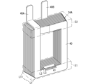
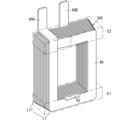
- FIG. 5 is a front view of the windings provided in the motor.
- FIG. 6 is a perspective view of a winding provided in the motor.
- FIG. 7 is a perspective view of a winding provided in the motor of the first modified example.
- FIG. 8 is a perspective view of a winding provided in the motor of the first modified example.
- FIG. 9 is a perspective view of a winding provided in the motor of the first modified example.
- FIG. 10 is a perspective view of a winding provided in a motor according to the second modification.
- FIG. 11 is a perspective view of a winding provided in a motor according to the third modification.
- FIG. 12 is a perspective view of a winding provided in a motor according to the fourth modification.
- FIG. 13 is a perspective view of a winding provided in a motor according to the fifth modification.
- FIG. 14 is a perspective view of a winding provided in a motor according to the fifth modification.
- FIG. 15 is a perspective view of a winding provided in a motor according to the sixth modification.
- Fig. 1 is a perspective view of a main part of a motor 1 according to an embodiment of the present disclosure.
- Fig. 2 is a plan view of the main part of the motor 1
- Fig. 3 is a cross-sectional view taken along line AA in Fig. 2.
- the motor 1 of this embodiment includes a rotor 2 and a stator 3.
- the rotor 2 has a cylindrical rotor yoke 22 and multiple magnets 23.
- the rotor yoke 22 has a rotating shaft 21 whose center of rotation is the axis Ax1.
- the multiple magnets 23 are arranged on the side of the rotor yoke 22 along the circumferential direction of the rotor yoke 22.
- the stator 3 has a cylindrical stator yoke 32, a number of teeth 33, and a number of windings 34.
- the stator yoke 32 is arranged concentrically with the rotor 2.
- the teeth 33 protrude from the inner surface of the stator yoke 32 toward the rotating shaft 21 from multiple positions around the rotor yoke 22.
- the multiple windings 34 are wound around each of the multiple teeth 33.
- Each of the multiple windings 34 is constructed by winding rectangular wire 40 in multiple layers, and has multiple layers L1 to L11 (for example, 11 in FIG. 4) that overlap in the protruding direction of the corresponding tooth 33 among the multiple teeth 33.
- a notch 41 (see Figures 5 and 6) is provided in one or more layers, including layer L1, which is closest to the rotor 2, among the multiple layers L1 to L11.
- the "axial direction" of the rotating shaft 21 is the direction in which the rotating shaft 21 extends and coincides with the axis Ax1 of the rotating shaft 21.
- the direction perpendicular to the extension direction of the axis Ax1 and radially expanding from the axis Ax1 of the rotating shaft 21 is the "radial direction” of the rotor yoke 22, and the direction in which the rotor yoke 22 revolves around the axis Ax1 of the rotating shaft 21, that is, the direction along the peripheral surface of the rotor yoke 22 is the "circumferential direction" of the rotor yoke 22.
- each of the multiple windings 34 has multiple layers L1 to L11 of wire 40, and of the multiple layers L1 to L11 of wire 40, the layer closest to the rotor 2 may be referred to as the first layer L1, and the nth layer counted from the rotor 2 side may be referred to as the nth layer Ln. Note that n is a positive integer.
- the windings being wound around the teeth may mean, for example, that the windings are wound around an insulating insulator provided on the teeth, or that the windings are wound directly around teeth whose surfaces have been subjected to an insulating treatment.
- the notch 41 is provided in one or more layers of the multiple layers L1 to L11 of the wire 40 of the winding 34, including the layer closest to the rotor 2 (first layer L1).
- leakage magnetic flux from the magnet 23 of the rotor 2 is likely to link with one or more layers, including the first layer L1, which is closest to the rotor 2.
- the notch 41 is provided in one or more layers, including the first layer L1, in each of the multiple windings 34, the distance between the winding 34 and the magnet 23 is longer than when the notch 41 is not provided. This makes it possible to reduce leakage magnetic flux linking with the wire 40 of the winding 34, and to reduce eddy current loss generated in the motor 1.
- the motor 1 is, for example, an inner rotor type brushless motor in which the rotor is disposed inside the stator 3.
- This motor 1 is driven by, for example, three-phase (U-phase, V-phase, W-phase) AC current that is 120 degrees out of phase with each other.
- the motor 1 includes a rotor 2, a stator 3, and a casing (not shown) that houses the rotor 2 and the stator 3.
- the rotor 2 includes the rotor yoke 22 and a plurality of magnets 23.
- the rotor yoke 22 is cylindrical and centered on the axis Ax1, with the axial dimension being smaller than the radial dimension.
- the rotor yoke 22 is formed, for example, by stacking multiple non-oriented magnetic steel plates in the axial direction.
- the rotor yoke 22 may be formed of iron, silicon steel, permalloy, ferrite, or the like.
- a circular hole is provided in the center of the rotor yoke 22.
- the rotating shaft 21 is inserted into the central hole of the rotor yoke 22, and the rotor yoke 22 is attached to the middle part of the rotating shaft 21 in the axial direction.
- the rotor yoke 22 is fixed to the rotating shaft 21, and rotates together with the rotating shaft 21 around the axis Ax1.
- the rotor 2 is, for example, a surface magnet type rotor.
- a plurality of magnets 23 are attached to the side of the rotor yoke 22 so as to be arranged at equal intervals in the circumferential direction of the rotor yoke 22.
- ten magnets 23 are attached at equal intervals to the circumferential surface of the rotor yoke 22.
- Each of the multiple magnets 23 is a permanent magnet, such as a neodymium magnet, formed into a rectangular parallelepiped shape.
- the multiple magnets 23 are arranged on the side of the rotor yoke 22 so that the magnetic poles are arranged alternately in the circumferential direction of the rotor yoke 22.
- the stator 3 has a stator core 31 and a plurality of windings 34 .
- the stator core 31 is constructed by combining the above-mentioned stator yoke 32 and a number of teeth 33.
- the stator yoke 32 is formed in a cylindrical shape.
- the stator yoke 32 is formed, for example, by stacking multiple non-oriented magnetic steel plates in the axial direction of the rotating shaft 21.
- the stator yoke 32 is arranged concentrically with the rotor 2. In other words, the central axis of the cylindrical stator yoke 32 coincides with the axis Ax1 of the rotating shaft 21 of the rotor yoke 22.
- a number of teeth 33 protrude toward the rotating shaft 21 from the inner peripheral surface of the stator yoke 32 so as to be arranged at equal intervals in the circumferential direction of the rotor yoke 22.
- Each of the teeth 33 is fixed to the stator yoke 32, for example, by fitting a portion of the tooth 33 into a groove provided in the stator yoke 32.
- the teeth 33 are arranged at equal intervals around the rotor yoke 22, and each of the teeth 33 faces the rotor yoke 22 in the radial direction.
- a winding 34 is wound around each of the teeth 33 via an insulating insulator.
- each of the teeth 33 faces the outer circumferential surface of the rotor 2 with a gap between them.
- 12 teeth 33 are arranged at equal intervals on the inner peripheral surface of the stator yoke 32, and a winding 34 is wound around each of the 12 teeth 33.
- the 12 windings 34 are divided into three groups corresponding to each of the three phases. Each group includes four windings 34 arranged at equal intervals in the circumferential direction of the rotor yoke 22.
- Fig. 4 is a perspective view of the main part showing a state in which one tooth 33 of the stator 3 faces one magnet 23 attached to the rotor yoke 22.
- Fig. 5 is a front view of only the winding 34
- Fig. 6 is a perspective view of only the winding 34.
- the windings 34 are edgewise windings formed by winding rectangular wire material (so-called rectangular wire) 40 made of, for example, copper or a copper alloy in multiple layers.
- Each of the multiple windings 34 has multiple (for example, 11) layers L1 to L11 that overlap in the protruding direction of a corresponding one of the multiple teeth 33.
- Both ends (first end 40A and second end 40B) of the wire material 40 that constitutes the windings 34 are drawn out in one direction, for example, parallel to the axial direction of the rotating shaft 21.
- the portions located outside the rotor yoke 22 when viewed from the radial direction of the rotor yoke 22 are called coil end portions E1 and E2.
- the portions that do not overlap with the rotor yoke 22 are called coil end portions E1 and E2.
- the coil end portions E1 and E2 are portions that do not contribute to the generation of an effective magnetic field that creates a rotating magnetic field that rotates the rotor 2.
- a notch 41 is provided in the coil end portion E1 of one of the coil end portions E1 and E2 on both sides of the rotor yoke 22 (the lower side in FIG. 5).
- the notch 41 is provided in the coil end portion E1 located outside the rotor yoke 22 when viewed from the radial direction of the rotor yoke 22.
- the magnetic flux emitted from the magnet 23A is not only the main magnetic flux, but also leakage magnetic flux that leaks outside the stator core 31.
- the leakage magnetic flux is mainly generated in the gap between the rotor 2 and the stator 3.
- this leakage flux interlinks with the winding 34 wound around the teeth 33A or 33B, an eddy current is generated in the winding 34, and an eddy current loss occurs according to this current.
- This eddy current loss becomes heat, which can lead to a rise in the temperature of the winding 34 and a decrease in the efficiency of the motor 1.
- the wire 40 of the winding 34 is a rectangular wire, which improves the space factor and reduces the DC resistance of the winding 34.
- the cross-sectional area of the leakage flux linkage is larger than when the wire 40 is a twisted wire or a round wire, and eddy currents may increase. Therefore, in this embodiment, as shown in Figures 5 and 6, a notch 41 is provided in a portion of the winding 34 where the leakage flux concentrates, for example, in the coil end portion E1 of the winding 34, and the length of the gap between the magnet 23 and the winding 34 can be longer than when the notch 41 is not provided. This reduces the leakage flux linking the winding 34 and reduces eddy current loss.
- the notch 41 is provided in the coil end portion E1, but may be provided in the coil end portion E2, or may be provided in both the coil end portions E1 and E2.
- the notch 41 is provided only in the portion of the winding 34 where leakage magnetic flux concentrates, for example, in the layer (first layer L1) closest to the rotor 2 among the multiple layers L1 to L11.
- the notch 41 in the first layer L1 of the winding 34 the length of the gap between the magnet 23 and the winding 34 is increased, so that the leakage magnetic flux linking the winding 34 can be reduced, and the generation of eddy currents is suppressed, thereby reducing eddy current loss.
- the method for forming the notch 41 in the winding 34 may be punching or cutting, and any appropriate method may be adopted.
- the notch 41 is provided in the first layer L1 of the winding 34 at an end facing the tooth 33.
- the notch 41 may be provided at the end opposite the end facing the tooth 33 in one or more layers of the winding 34, and the position at which the notch 41 is provided may be changed as appropriate.
- the notch 41 is provided in one or more layers, including the layer L1 closest to the rotor 2, in all of the multiple windings 34 wound around the multiple teeth 33.
- the notch 41 may be provided in one or more layers, including the layer L1 closest to the rotor 2, in some of the multiple windings 34 wound around the multiple teeth 33.
- the notch 41 is provided only in the first layer L1, but in the winding 34A of the first modification example, the notch 41 is provided in multiple layers including the first layer L1.
- FIG. 7 is a perspective view of the winding 34A provided in the motor 1 of the first modification.
- the first layer L1 and the second layer L2 have a notch 41 at the same position when viewed from the radial direction of the rotor yoke 22.
- the leakage magnetic flux interlinked with the winding 34A can be further reduced, and eddy current loss can be further reduced.
- the number of layers in which the notches 41 are provided among the multiple layers of the winding 34A can be changed as appropriate.
- the three layers, the first layer L1 to the third layer L3, of the winding 34A may have the notch 41 at the same position as seen from the radial direction of the rotor yoke 22.
- the notch 41 may be provided at the same position as seen from the radial direction of the rotor yoke 22 in all of the layers L1 to L11 of the winding 34A.
- the notch 41 is provided in each of the multiple layers, it is preferable that the multiple notches 41 provided in each of the multiple layers are provided at the same position as seen from the radial direction of the rotor yoke 22.
- the notch 41 is provided at the end facing the tooth 33 in each of the multiple layers of the winding 34A, but the notch 41 may be provided at the end opposite the end facing the tooth 33, and the position at which the notch 41 is provided can be changed as appropriate.
- the notch 41 is provided in the coil end portion E1, but the notch 41 may be provided in the coil end portion E2, or the notch 41 may be provided in both the coil end portions E1 and E2.
- the motor 1 according to the second modification differs from the above embodiment in that the layer (first layer L1) closest to the rotor 2 among the multiple layers of the winding 34B has a notch 42 extending to the middle of the thickness direction.
- the notch 42 is provided only in the first layer L1 of the winding 34B, up to the middle of the first layer L1 in the thickness direction. In this way, the notch 42 does not penetrate the first layer L1 of the winding 34B, so the cross-sectional area of the first layer L1 can be made larger than when the notch 41 penetrates the first layer L1 as in the above embodiment. Therefore, in the motor 1 of variant 2, by providing the notch 42 up to the middle of the first layer L1 in the thickness direction while reducing the resistance of the winding 34B, it is possible to reduce the leakage magnetic flux that links to the winding 34B and reduce eddy current loss.
- the multiple layers of the winding 34B have a notch 42 at the end facing the tooth 33, but the notch 42 may be provided at the end opposite the end facing the tooth 33, and the position at which the notch 42 is provided can be changed as appropriate.
- the notch 42 is provided in the coil end portion E1, but the notch 42 may be provided in the coil end portion E2, or the notch 42 may be provided in both the coil end portions E1 and E2.
- the cutout 41 is formed by providing a rectangular recess at the end of the first layer L1 of the winding 34, but the shape of the cutout can be changed as appropriate.
- one or more layers have a notch 43 at the end facing the tooth 33.
- the shape of the notch 43 when viewed from the radial direction of the rotor yoke 22 is formed so that the width of the notch 43 in the winding direction of the wire 40 increases as it approaches the tooth 33.
- the end of the notch 43 is inclined obliquely relative to the end face of the wire 40, which has the advantage of being easier to process compared to when the end of the notch 43 intersects the end face of the wire 40 at a right angle.
- FIG. 11 shows only one example of the shape of the cutout portion 43, and the shape of the cutout portion 43 can be changed as appropriate.
- the notch 43 is provided in the coil end portion E1, but the notch 43 may be provided in the coil end portion E2, or the notch 43 may be provided in both the coil end portions E1 and E2.
- the notch 41 is formed by providing a recess at the end of the first layer L1 of the winding 34, but the shape of the notch can be changed as appropriate.
- a notch 44 which is a through hole penetrating the first layer L1 is provided in the center of the width direction (direction perpendicular to the winding direction) of the wire 40 in the first layer L1. That is, in the fourth modified example, the notch 44 is a hole with a closed periphery. In this way, even when the notch 44 is a hole with a closed periphery, the leakage magnetic flux that links to the winding 34D is reduced compared to when the notch 44 is not provided, and eddy current loss can be reduced.
- the notch 44 may be formed to penetrate multiple layers of the winding 34D.
- the cutout portion 44 is provided in the coil end portion E1, but it may also be provided in the coil end portion E2, or may be provided in both the coil end portions E1 and E2. In addition, the cutout portion 44 may be a hole that penetrates multiple layers including the first layer L1.
- the coil end E1 of the winding 34 has a notch 41, but in the fifth modification, the first layer L1 of the winding 34E has notches 45 (see FIG. 13) at intermediate portions F1 and F2 between the coil end E1 and the coil end E2. That is, in the first layer L1 of the winding 34E, the two intermediate portions F1 and F2 that face each other in the circumferential direction of the rotor yoke 22 have notches 45. More specifically, the first layer L1 of the winding 34E has notches 45 at the ends of the intermediate portions F1 and F2 that face the teeth 33.
- the first layer L1 of the winding 34E may have notches 46 at the ends of the intermediate portions F1 and F2, opposite the ends facing the teeth 33.
- the notches 45, 46 are provided only in the first layer L1, and the notches 45, 46 may be provided in multiple layers. Furthermore, it is not essential that the notches 45, 46 are provided in both intermediate portions F1, F2 of the winding 34E, and the notches 45, 46 may be provided in only one of the intermediate portions F1, F2.
- a notch 41 is formed at one location in the coil end portion E1 of the first layer L1 of the winding 34, but the position and number of the notches can be changed as appropriate.
- three notches 47 are provided at multiple positions (e.g., three positions) in the coil end portion E1 of the first layer L1 of the winding 34F.
- one or more of the multiple layers of the winding 34F may have notches 47 at multiple positions in the winding direction of the wire 40, which reduces the leakage flux that links to the winding 34F and reduces eddy current loss.
- the number and positions of the cutouts 41 to 46 can be changed as appropriate, and multiple cutouts 41 to 46 may be provided in one or more layers including at least the first layer L1.
- a notch 41 may be provided in one or more layers, including the layer L1 closest to the rotor 2.
- the motor (1) of the first aspect includes a rotor (2) and a stator (3).
- the rotor (2) includes a cylindrical rotor yoke (22) having a rotation axis (21) with an axis (Ax1) as a rotation center, and a plurality of magnets (23) arranged on the side of the rotor yoke (22) along the circumferential direction of the rotor yoke (22).
- the stator (3) includes a cylindrical stator yoke (32), a plurality of teeth (33), and a plurality of windings (34, 34A to 34F).
- the stator yoke (32) is arranged concentrically with the rotor (2).
- the plurality of teeth (33) protrude from a plurality of positions on the inner peripheral surface of the stator yoke (32) in the circumferential direction of the rotor yoke (22) toward the rotation axis (21).
- the plurality of windings (34, 34A to 34F) are wound around the plurality of teeth (33), respectively.
- Each of the multiple windings (34, 34A-34F) is constructed by winding a rectangular wire (40) in multiple layers, and has multiple layers (L1-L11) that overlap in the protruding direction of the corresponding tooth (33) among the multiple teeth (33).
- notches (41-47) are provided in one or more layers (L1-L11) of the multiple layers (L1-L11), including the layer (L1) closest to the rotor (2).
- the length of the gap between the magnet (23) and the windings (34, 34A-34F) can be made longer than when the notches (41-47) are not provided, so that the leakage flux interlinked with the windings (34, 34A-34F) can be reduced, and eddy current loss can be further reduced.
- one or more layers (L1 to L11) are provided with notches (41 to 43, 45, 47) at the ends facing the teeth (33).
- the shape of the notch (43) when viewed from the radial direction of the rotor yoke (22) is formed so that the width of the notch (43) in the winding direction of the wire (40) increases as it approaches the teeth (33).
- This embodiment has the advantage that the cutout portion (43) is easy to process.
- the notches (41-47) are provided only in the layer (L1) of the multiple layers (L1-L11) that is closest to the rotor (2).
- This embodiment makes it possible to reduce the leakage flux interlinking with the windings (34, 34A to 34F) while lowering the resistance of the windings (34, 34B to 34F), thereby further reducing eddy current loss.
- a notch (42) is provided up to the middle of the thickness direction in the layer (L1) closest to the rotor (2) among the multiple layers (L1 to L11).
- the cutout portion (44) is a hole whose periphery is closed.
- This embodiment reduces the leakage flux that interlinks with the winding (34D), further reducing eddy current loss.
- one or more layers (L1 to L11) are provided with notches (47) at multiple positions in the winding direction of the wire (40).
- This embodiment reduces the leakage flux that interlinks with the winding (34F), further reducing eddy current loss.
- the coil end portions (E1, E2) located on the outer side of the rotor yoke (22) as viewed in the radial direction of the rotor yoke (22) are provided with cutout portions (41 to 44, 47).
- the configurations according to the second to eighth aspects are not essential to the motor (1) and may be omitted as appropriate.
Landscapes
- Engineering & Computer Science (AREA)
- Power Engineering (AREA)
- Iron Core Of Rotating Electric Machines (AREA)
Priority Applications (1)
| Application Number | Priority Date | Filing Date | Title |
|---|---|---|---|
| JP2024571733A JPWO2024154677A1 (https=) | 2023-01-17 | 2024-01-12 |
Applications Claiming Priority (2)
| Application Number | Priority Date | Filing Date | Title |
|---|---|---|---|
| JP2023-005304 | 2023-01-17 | ||
| JP2023005304 | 2023-01-17 |
Publications (1)
| Publication Number | Publication Date |
|---|---|
| WO2024154677A1 true WO2024154677A1 (ja) | 2024-07-25 |
Family
ID=91956111
Family Applications (1)
| Application Number | Title | Priority Date | Filing Date |
|---|---|---|---|
| PCT/JP2024/000693 Ceased WO2024154677A1 (ja) | 2023-01-17 | 2024-01-12 | モータ |
Country Status (2)
| Country | Link |
|---|---|
| JP (1) | JPWO2024154677A1 (https=) |
| WO (1) | WO2024154677A1 (https=) |
Citations (4)
| Publication number | Priority date | Publication date | Assignee | Title |
|---|---|---|---|---|
| JP2011234443A (ja) * | 2010-04-26 | 2011-11-17 | Aisin Seiki Co Ltd | コイルおよび電機子 |
| JP2012186938A (ja) * | 2011-03-07 | 2012-09-27 | Denso Corp | 電機子 |
| WO2019203076A1 (ja) * | 2018-04-18 | 2019-10-24 | パナソニックIpマネジメント株式会社 | コイル及びそれを用いたモータ |
| WO2021117320A1 (ja) * | 2019-12-12 | 2021-06-17 | パナソニックIpマネジメント株式会社 | コイル及びそれを備えたモータ |
-
2024
- 2024-01-12 WO PCT/JP2024/000693 patent/WO2024154677A1/ja not_active Ceased
- 2024-01-12 JP JP2024571733A patent/JPWO2024154677A1/ja active Pending
Patent Citations (4)
| Publication number | Priority date | Publication date | Assignee | Title |
|---|---|---|---|---|
| JP2011234443A (ja) * | 2010-04-26 | 2011-11-17 | Aisin Seiki Co Ltd | コイルおよび電機子 |
| JP2012186938A (ja) * | 2011-03-07 | 2012-09-27 | Denso Corp | 電機子 |
| WO2019203076A1 (ja) * | 2018-04-18 | 2019-10-24 | パナソニックIpマネジメント株式会社 | コイル及びそれを用いたモータ |
| WO2021117320A1 (ja) * | 2019-12-12 | 2021-06-17 | パナソニックIpマネジメント株式会社 | コイル及びそれを備えたモータ |
Also Published As
| Publication number | Publication date |
|---|---|
| JPWO2024154677A1 (https=) | 2024-07-25 |
Similar Documents
| Publication | Publication Date | Title |
|---|---|---|
| EP3457534B1 (en) | Rotating electric machine | |
| JP6592234B2 (ja) | 単相ブラシレスモータ | |
| CN104335467B (zh) | 电机 | |
| CN204179905U (zh) | 同步电动机 | |
| JP6222032B2 (ja) | 回転電機 | |
| JP6048191B2 (ja) | マルチギャップ型回転電機 | |
| US20170040855A1 (en) | Rotor for a rotary electric machine | |
| JP7185414B2 (ja) | 回転子鉄心、回転子及び同期リラクタンス回転電機 | |
| JP7685829B2 (ja) | 電動機 | |
| KR102652587B1 (ko) | 회전 전기 기계 | |
| JP2023161096A (ja) | 回転電機 | |
| CN114846724A (zh) | 具有可变气隙的同步磁阻机 | |
| JP2022076731A (ja) | 回転電機 | |
| WO2024154677A1 (ja) | モータ | |
| US10666097B2 (en) | Switched reluctance electric machine including pole flux barriers | |
| JP7258824B2 (ja) | 回転電機 | |
| TW202203549A (zh) | 旋轉電機 | |
| WO2024195734A1 (ja) | モータ | |
| JP7627201B2 (ja) | 回転電機 | |
| JP7600065B2 (ja) | 回転電機 | |
| WO2021182088A1 (ja) | 永久磁石同期モータ | |
| JP7814523B2 (ja) | ロータコア、ロータ、回転電機及びロータコアの設計方法 | |
| JP7578081B2 (ja) | 回転電機 | |
| JP5924913B2 (ja) | 発電機 | |
| WO2022264787A1 (ja) | ステータ及び回転電動機 |
Legal Events
| Date | Code | Title | Description |
|---|---|---|---|
| 121 | Ep: the epo has been informed by wipo that ep was designated in this application |
Ref document number: 24744600 Country of ref document: EP Kind code of ref document: A1 |
|
| ENP | Entry into the national phase |
Ref document number: 2024571733 Country of ref document: JP Kind code of ref document: A |
|
| WWE | Wipo information: entry into national phase |
Ref document number: 2024571733 Country of ref document: JP |
|
| NENP | Non-entry into the national phase |
Ref country code: DE |
|
| 122 | Ep: pct application non-entry in european phase |
Ref document number: 24744600 Country of ref document: EP Kind code of ref document: A1 |