WO2024154314A1 - 工作機械の制御装置 - Google Patents
工作機械の制御装置 Download PDFInfo
- Publication number
- WO2024154314A1 WO2024154314A1 PCT/JP2023/001598 JP2023001598W WO2024154314A1 WO 2024154314 A1 WO2024154314 A1 WO 2024154314A1 JP 2023001598 W JP2023001598 W JP 2023001598W WO 2024154314 A1 WO2024154314 A1 WO 2024154314A1
- Authority
- WO
- WIPO (PCT)
- Prior art keywords
- machining
- index value
- upper limit
- workpiece
- acquisition unit
- Prior art date
- Legal status (The legal status is an assumption and is not a legal conclusion. Google has not performed a legal analysis and makes no representation as to the accuracy of the status listed.)
- Ceased
Links
Images




Classifications
-
- G—PHYSICS
- G05—CONTROLLING; REGULATING
- G05B—CONTROL OR REGULATING SYSTEMS IN GENERAL; FUNCTIONAL ELEMENTS OF SUCH SYSTEMS; MONITORING OR TESTING ARRANGEMENTS FOR SUCH SYSTEMS OR ELEMENTS
- G05B19/00—Program-control systems
- G05B19/02—Program-control systems electric
- G05B19/18—Numerical control [NC], i.e. automatically operating machines, in particular machine tools, e.g. in a manufacturing environment, so as to execute positioning, movement or co-ordinated operations by means of program data in numerical form
- G05B19/404—Numerical control [NC], i.e. automatically operating machines, in particular machine tools, e.g. in a manufacturing environment, so as to execute positioning, movement or co-ordinated operations by means of program data in numerical form characterised by control arrangements for compensation, e.g. for backlash, overshoot, tool offset, tool wear, temperature, machine construction errors, load, inertia
-
- G—PHYSICS
- G05—CONTROLLING; REGULATING
- G05B—CONTROL OR REGULATING SYSTEMS IN GENERAL; FUNCTIONAL ELEMENTS OF SUCH SYSTEMS; MONITORING OR TESTING ARRANGEMENTS FOR SUCH SYSTEMS OR ELEMENTS
- G05B19/00—Program-control systems
- G05B19/02—Program-control systems electric
- G05B19/18—Numerical control [NC], i.e. automatically operating machines, in particular machine tools, e.g. in a manufacturing environment, so as to execute positioning, movement or co-ordinated operations by means of program data in numerical form
- G05B19/406—Numerical control [NC], i.e. automatically operating machines, in particular machine tools, e.g. in a manufacturing environment, so as to execute positioning, movement or co-ordinated operations by means of program data in numerical form characterised by monitoring or safety
- G05B19/4068—Verifying part program on screen, by drawing or other means
-
- G—PHYSICS
- G05—CONTROLLING; REGULATING
- G05B—CONTROL OR REGULATING SYSTEMS IN GENERAL; FUNCTIONAL ELEMENTS OF SUCH SYSTEMS; MONITORING OR TESTING ARRANGEMENTS FOR SUCH SYSTEMS OR ELEMENTS
- G05B2219/00—Program-control systems
- G05B2219/30—Nc systems
- G05B2219/37—Measurements
- G05B2219/37434—Measuring vibration of machine or workpiece or tool
-
- G—PHYSICS
- G05—CONTROLLING; REGULATING
- G05B—CONTROL OR REGULATING SYSTEMS IN GENERAL; FUNCTIONAL ELEMENTS OF SUCH SYSTEMS; MONITORING OR TESTING ARRANGEMENTS FOR SUCH SYSTEMS OR ELEMENTS
- G05B2219/00—Program-control systems
- G05B2219/30—Nc systems
- G05B2219/49—Nc machine tool, till multiple
- G05B2219/49277—Oscillating, swinging feed drive, for grinding
-
- G—PHYSICS
- G05—CONTROLLING; REGULATING
- G05B—CONTROL OR REGULATING SYSTEMS IN GENERAL; FUNCTIONAL ELEMENTS OF SUCH SYSTEMS; MONITORING OR TESTING ARRANGEMENTS FOR SUCH SYSTEMS OR ELEMENTS
- G05B2219/00—Program-control systems
- G05B2219/30—Nc systems
- G05B2219/49—Nc machine tool, till multiple
- G05B2219/49314—Machine with oscillating workpiece, no full rotation
-
- G—PHYSICS
- G05—CONTROLLING; REGULATING
- G05B—CONTROL OR REGULATING SYSTEMS IN GENERAL; FUNCTIONAL ELEMENTS OF SUCH SYSTEMS; MONITORING OR TESTING ARRANGEMENTS FOR SUCH SYSTEMS OR ELEMENTS
- G05B2219/00—Program-control systems
- G05B2219/30—Nc systems
- G05B2219/49—Nc machine tool, till multiple
- G05B2219/49384—Control of oscillatory movement like filling a weld, weaving
Definitions
- This disclosure relates to a control device for a machine tool.
- oscillating cutting in which the cutting tool and the workpiece are oscillated relative to each other while cutting the workpiece.
- index values showing the processing state such as feed rate, oscillation frequency, and oscillation amplitude
- each index value may be corrected.
- resonance may occur, making it impossible to guarantee the safety of the machine, or the processing surface may deteriorate due to not meeting the recommended processing conditions.
- This disclosure has been made in consideration of the above problems, and aims to provide a technology in a machine tool control device that can appropriately set the range in which oscillation is stopped when an index value indicating the machining state exceeds an upper limit value.
- the present disclosure also provides a control device for a machine tool that performs machining while swinging a cutting tool and a workpiece relative to one another, the control device for a machine tool including a machining state acquisition unit that acquires an index value indicating a machining state, a machining upper limit value acquisition unit that acquires an upper limit value of the index value indicating the machining state, a program command acquisition unit that acquires command information of a machining program, and a swing operation execution determination unit that determines whether or not to execute a swing operation that swings the cutting tool and the workpiece relative to one another based on the machining program, and the swing operation execution determination unit sets a swing stop range so that the swing operation is not executed throughout the entire machining program when there is a location in the machining program consisting of a plurality of machining blocks where the index value exceeds the upper limit value.
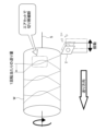
- FIG. 13 is a diagram for explaining swing cutting.
- 1 is a functional block diagram of a control device for a machine tool according to a first embodiment of the present invention.
- FIG. FIG. 4 is a functional block diagram of a machining state acquisition unit.
- FIG. 13 is a diagram illustrating the maximum distance between paths in a cutting path.
- 11 is a diagram showing an example of an index value calculated by a machining state acquisition unit.
- FIG. 13 is a diagram showing an example of an upper limit value acquired by a processing upper limit value acquisition unit; FIG.
- FIGS. 11A and 11B are diagrams illustrating a first example of a range in which a rocking action is not performed by the rocking action execution determination unit of the first embodiment
- 13 is a diagram illustrating a second example of a range in which a rocking action is not performed by the rocking action execution determination unit of the first embodiment
- FIG. 10 is a flowchart showing an example of a flow of a swing determination process performed by a numerical control device of a machine tool.
- 13A and 13B are diagrams illustrating examples of ranges in which a rocking action is not performed by a rocking action execution determination unit according to the second embodiment;
- FIG. 11 is a functional block diagram of a control device for a machine tool according to a modified example of the present invention.
- a numerical control device 1 for a machine tool according to a first embodiment of the present invention is for controlling a machine tool that performs machining while relatively swinging a cutting tool T and a workpiece W. First, swing cutting will be described with reference to FIG.
- FIG. 1 is a diagram for explaining oscillating cutting.
- at least one spindle S that rotates the cutting tool T and the workpiece W relative to each other and at least one feed axis (not shown) that moves the cutting tool T relative to the workpiece W are operated to rotate the cutting tool T and the workpiece W relative to each other and to perform cutting while oscillating the cutting tool T and the workpiece W relative to each other in the feed direction.
- the tool path which is the trajectory of the cutting tool T, is set so that the current path partially overlaps with the previous path.
- the current path partially includes the part that has been machined in the previous path, generating an air cut called an air cut, in which the cutting edge of the cutting tool T separates from the surface of the workpiece W, and the cutting chips are chopped up.
- the shape of the workpiece is not limited in the oscillating cutting performed in this embodiment. In other words, it can be applied even when the workpiece has a tapered portion or an arc-shaped portion on the machining surface, requiring multiple feed axes (Z axis and X axis), or when the workpiece is cylindrical or cylindrical and only one specific feed axis (Z axis) is sufficient.
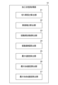
- Figure 2 is a functional block diagram of the numerical control device 1 of the machine tool according to one embodiment of the present invention.
- the numerical control device 1 of the machine tool of this embodiment is configured using a computer equipped with memories such as ROM (read only memory) and RAM (random access memory), a CPU (control processing unit), and a communication control unit, which are connected to each other via a bus.
- memories such as ROM (read only memory) and RAM (random access memory), a CPU (control processing unit), and a communication control unit, which are connected to each other via a bus.
- ROM read only memory
- RAM random access memory
- CPU control processing unit
- communication control unit which are connected to each other via a bus.
- the functions and operations of each functional unit described below are achieved by the cooperation of the CPU, memory, and control programs stored in the memory mounted on the computer.
- the numerical control device 1 of the machine tool may also be configured with a CNC (Computer Numerical Controller) or a PLC (Programmable Logic Controller), and may be connected to a higher-level computer that outputs machining conditions such as rotation speed in addition to the machining program.
- CNC Computer Numerical Controller
- PLC Programmable Logic Controller
- the numerical control device 1 of the machine tool includes, as functional units, a condition acquisition unit 11, a machining state acquisition unit 12, a machining upper limit value acquisition unit 13, a program command acquisition unit 14, a swing operation execution determination unit 15, and a memory unit 20.
- the condition acquisition unit 11 acquires the machining conditions and the oscillation conditions.
- the machining conditions and the oscillation conditions are stored, for example, in the memory unit 20 as a machining program or setting parameters of the machine tool.
- the condition acquisition unit 11 may acquire the machining conditions and the oscillation conditions from an external memory unit or an external computer external to the numerical control device 1.
- the machining conditions include at least information regarding the relative feed amount per revolution between the cutting tool and the workpiece, and information regarding the shape of the cutting tool cutting edge, as well as information regarding, for example, the spindle speed S (1/min), the feed rate of the cutting tool (mm/min), the workpiece diameter (mm), the clearance angle of the cutting tool (°), etc.
- information regarding the relative feed amount per revolution between the cutting tool and the workpiece includes the feed amount per revolution F (mm/rev)
- information regarding the shape of the cutting tool cutting edge includes the radius of the cutting edge (mm).
- the oscillation conditions include information on the relative oscillation number per revolution between the cutting tool and the workpiece, and information on the oscillation amplitude relative to the feed amount per revolution between the cutting tool and the workpiece.
- Information on the relative oscillation number per revolution between the cutting tool and the workpiece includes an oscillation frequency magnification I (times), which indicates the oscillation frequency per revolution of the spindle.
- Information on the oscillation amplitude relative to the relative feed amount per revolution between the cutting tool and the workpiece includes an oscillation amplitude magnification K (times), which indicates the magnitude of the oscillation amplitude relative to the magnitude of the feed amount per revolution of the spindle.
- the oscillation frequency magnification I may be specified directly, or may be calculated from the oscillation frequency (Hz) and the spindle rotation speed S (1/min) after specifying the oscillation frequency (Hz).
- the oscillation amplitude magnification K may be specified directly, or may be calculated from the oscillation amplitude (mm), the feed rate (mm/min), and the spindle rotation speed S (1/min) after specifying the oscillation amplitude (mm).
- the machining state acquisition unit 12 calculates an index value indicating the machining state based on the machining conditions and oscillation conditions input from the condition acquisition unit 11. An example of an index calculated by the machining state acquisition unit 12 will be described with reference to FIG. 3.
- FIG. 3 is a functional block diagram of the machining state acquisition unit. An example of a determination method and a calculation method of the machining state acquisition unit 12 will be described.
- Y represents the coordinate value in the feed direction (mm)
- f represents the feed amount F (mm/rev) per one rotation of the spindle
- S represents the spindle speed (1/min)
- t represents time (sec)
- I represents the oscillation frequency multiplier (times)
- K represents the oscillation amplitude multiplier (times)
- r represents the workpiece diameter (mm), which is the radius of the workpiece W
- R represents the cutting edge (mm), which is the shape of the cutting edge of the nose, etc.
- h represents the maximum height Rz ( ⁇ m), which is an index of surface roughness.
- the machining state acquisition unit 12 includes a chip length calculation unit 21, a surface roughness calculation unit 22, an oscillation frequency calculation unit 23, an oscillation amplitude calculation unit 24, a maximum speed calculation unit 25, a maximum acceleration calculation unit 26, and a maximum jerk calculation unit 27.
- the chip length calculation unit 21 calculates the length of the chip of the workpiece W as an index value based on the machining conditions and the oscillation conditions.
- the machining condition used to calculate the chip length is, for example, the workpiece diameter (mm), which is the radius of the workpiece W.
- the oscillation condition used to calculate the chip length is, for example, the oscillation frequency magnification I (times), which indicates the oscillation frequency per rotation of the spindle.
- the chip length calculation unit 21 calculates the chip length using the following formula (1).
- the surface roughness calculated by the surface roughness calculation unit 22 includes at least one of the following: arithmetic mean roughness; maximum height, which is the maximum distance between a peak and a valley; maximum peak height, which is the maximum height from the mean line of the surface; maximum valley depth, which is the absolute value of the minimum height from the mean line of the surface; average height, which is the average value of the heights of the profile curve elements consisting of adjacent peaks and valleys as a set; maximum cross-sectional height, which is the sum of the maximum peak height and maximum valley depth of the profile curve element; and load length ratio, which is the ratio of the load length of the profile curve element at a specified cutting level (height % or ⁇ m) to the evaluation reference length.
- the surface roughness is not limited to the maximum height Rz.
- the surface roughness may be, for example, the arithmetic mean roughness Ra.
- the oscillation frequency calculation unit 23 calculates the oscillation frequency in the relative oscillation of the cutting tool T and the workpiece W as an index value based on the machining conditions and the oscillation conditions.
- the machining conditions used to calculate the oscillation frequency are, for example, the rotation speed S (1/min) of the spindle.
- the oscillation conditions used to calculate the oscillation frequency are, for example, the oscillation frequency magnification I (times) indicating the oscillation frequency per rotation of the spindle.
- the oscillation frequency calculation unit 23 calculates the oscillation frequency using the following formula (4).
- the oscillation amplitude calculation unit 24 calculates the oscillation amplitude in the relative oscillation of the cutting tool T and the workpiece W as an index value based on the machining conditions and the oscillation conditions.
- the machining conditions used to calculate the oscillation amplitude are, for example, the feed amount per revolution F (mm/rev).
- the oscillation conditions used to calculate the oscillation amplitude are, for example, the oscillation amplitude magnification K (times), which indicates the magnitude of the oscillation amplitude relative to the magnitude of the feed amount per revolution of the spindle.
- the oscillation amplitude calculation unit 24 calculates the oscillation amplitude using the following formula (5).
- the maximum acceleration calculation unit 26 calculates the maximum speed of the relative oscillation of the cutting tool T and the workpiece W as an index value based on the machining conditions and the oscillation conditions.
- the machining conditions used to calculate the maximum speed are, for example, the spindle rotation speed S (1/min) and the feed rate F (mm/rev).
- the oscillation conditions used to calculate the maximum acceleration are, for example, the oscillation amplitude magnification K (times) indicating the magnitude of the oscillation amplitude relative to the feed rate per rotation of the spindle, and the oscillation frequency magnification I (times) indicating the oscillation frequency per rotation of the spindle.
- the maximum speed calculation unit 25 calculates the maximum speed using the following formula (6).
- the maximum jerk calculation unit 27 calculates the maximum jerk in the relative oscillation of the cutting tool T and the workpiece W as an index value based on the machining conditions and the oscillation conditions.
- the machining conditions used to calculate the maximum jerk are, for example, the spindle rotation speed S (1/min) and the feed rate F (mm/rev).
- the oscillation conditions used to calculate the maximum acceleration are, for example, an oscillation amplitude magnification K (times) indicating the magnitude of the oscillation amplitude relative to the magnitude of the feed rate per rotation of the spindle, and an oscillation frequency magnification I (times) indicating the oscillation frequency per rotation of the spindle.
- the maximum jerk calculation unit 27 calculates the maximum jerk using the following formula (8).
- the above describes the configuration of the processing state acquisition unit 12. Note that the above-mentioned method of calculating the index value is just one example, and the processing state index value may be calculated using a method other than the method using the above-mentioned formula.
- the machining upper limit value acquisition unit 13 acquires the following as upper limit values: oscillation frequency (Hz): 150, oscillation amplitude (mm): 1.0, maximum speed (mm/s): 120.00, maximum acceleration (mm/ s2 ): 200000.00, maximum jerk (mm/ s3 ): 200000000.00, chip length (mm): 150.0, and maximum surface roughness ( ⁇ m): 300.0.
- the program command acquisition unit 14 acquires command information of the machining program.
- the command information of the machining program includes information for identifying the location of an index value that indicates the machining state. For example, when the entire machining program is configured to consist of multiple machining blocks, the command information includes information for identifying the machining block to which the index value corresponds and information for identifying the location of the index value in the machining block.
- the swinging operation execution determination unit 15 determines whether or not swinging should be performed based on an index value indicating the processing state and an upper limit value corresponding to the index value.
- the processing by the swinging operation execution determination unit 15 may be performed in advance before processing begins, or may be performed sequentially in real time during processing.
- the oscillation operation execution determination unit 15 sets a range in which oscillation operation is not performed based on the command information of the machining program.
- the range in which oscillation operation is not performed is appropriately specified as a machining block, unit cutting section, etc.
- FIG. 7 is a diagram that shows a schematic diagram of a first example of a range in which a rocking motion is not performed by the rocking motion execution determination unit 15 in the first embodiment.
- FIG. 7 shows a schematic example of a machining program 100 composed of multiple machining blocks 101-104.
- machining corresponding to the commands of each of the machining blocks 101-104 is executed in the order of machining block 101, machining block 102, machining block 103, and machining block 104.
- the range beyond point 110 where the index value in the same processing block 102 exceeds the upper limit is set as a range in which no oscillation operation is performed. Therefore, even within the same processing block 102, the oscillation operation is performed before point 110 where the index value exceeds the upper limit. In addition, the oscillation operation is also performed in processing blocks 101, 103, and 104 that are different from processing block 102.
- FIG. 8 is a diagram that shows a schematic diagram of a second example of the range in which the rocking motion is not performed by the rocking motion execution determination unit 15 in the first embodiment.
- processing blocks 103 and 104 are also set as ranges where no oscillation operation is performed. In other words, no oscillation operation is performed across multiple processing blocks 102-103. Note that for processing block 101, because this is before the occurrence of an event where the index value exceeds the upper limit corresponding to the index value (point 110 where the index value exceeds the upper limit), an oscillation operation will be performed if an oscillation condition is set.
- the range in which no oscillation occurs is not limited to the first or second example.
- the processing block 103 next to the processing block 102 in which an event that exceeds the upper limit value corresponding to the index value occurs can be set to a range in which no oscillation occurs. This makes it possible to avoid sudden changes in control when performing real-time processing, and achieves more stable processing.
- Constant peripheral speed control is a control that cuts the workpiece W at the same relative speed by rotating the spindle faster if the workpiece diameter is small and rotating the spindle slower if the workpiece diameter is large.
- this constant peripheral speed control there is a risk that the speed of the spindle will increase and exceed the upper limit value due to the diameter of the workpiece W becoming smaller during processing.
- by setting a range in which no oscillating operation is performed corresponding to the range in which constant peripheral speed control is performed it is possible to more reliably avoid a situation in which oscillating processing is performed when the upper limit value is exceeded.
- Spindle override is a function that adjusts the feed rate and rotation speed during cutting using dials, etc., but this function can prevent oscillating machining from being performed when the index value exceeds the upper limit, even if the index value exceeds the upper limit.
- the memory unit 20 stores various information for controlling and machining the machine tool.
- the memory unit 20 stores machining conditions, oscillation conditions, etc.
- the machining conditions and oscillation conditions are, for example, input by an operator as a machining program or specified as machine tool parameters.
- the memory unit 20 may be configured to be located outside the numerical control device 1 instead of inside it.
- Figure 9 is a flowchart showing an example of the flow of the oscillation determination process by the numerical control device 1 of a machine tool.
- the program command acquisition unit 14 acquires commands for the machining program from the memory unit 20, etc. (step S1).
- the condition acquisition unit 11 acquires machining conditions and oscillation conditions based on the machining program and parameters stored in the memory unit 20, etc. (step S2). Note that there is no particular limitation on the targets from which the program command acquisition unit 14 and the condition acquisition unit 11 acquire information.
- the machining state acquisition unit 12 acquires index values based on the machining conditions and oscillation conditions acquired by the condition acquisition unit 11 (step S3).
- the machining state acquisition unit 12 calculates the chip length, surface roughness, oscillation frequency, oscillation amplitude, maximum speed, maximum acceleration, and maximum jerk as index values based on the machining conditions and oscillation conditions.
- step S4 the swinging operation execution determination unit 15 compares the multiple types of index values acquired by the machining state acquisition unit 12 with the upper limit values for those index values (step S5). If there is no index value that exceeds the upper limit value, the swinging operation execution determination unit 15 advances the process to step S6 (step S5; NO). If there is an index value that exceeds the upper limit value, the swinging operation execution determination unit 15 advances the process to step S7 (step S5; YES).
- step S6 the swing operation execution determination unit 15 determines that since there is no index value that exceeds the upper limit, swing operation should be turned on and swing processing should be performed as instructed by the machining program.
- step S7 since the index value exceeds the upper limit, the swing operation execution determination unit 15 determines that a range in which swing processing is not performed should be set and swing-OFF (no swing) processing should be performed, as described above.
- the above-described first embodiment of the numerical control device 1 for a machine tool provides the following effects.
- the numerical control device 1 of the machine tool of this embodiment includes a machining state acquisition unit 12 that acquires an index value indicating the machining state, a machining upper limit value acquisition unit 13 that acquires an upper limit value of the index value indicating the machining state, a program command acquisition unit 14 that acquires command information of the machining program 100, and a swing operation execution determination unit 15 that determines whether or not to execute a swing operation that swings the cutting tool T and the workpiece relatively based on the machining program 100.
- the swing operation execution determination unit 15 sets the swing stop range so that the swing operation is not executed after the point where the index value exceeds the upper limit value in the machining program 100.
- the range in which oscillation is stopped is the range from the location 110 in the processing block 102 containing the location 110 where the index value exceeds the upper limit value, among the multiple processing blocks 101 to 104 that make up the processing program 100.
- oscillation processing is performed until the index value exceeds the upper limit value in the same processing block 102, and the range in which oscillation processing is not performed can be reduced as much as possible.
- the range in which the oscillation is stopped is the range beyond the point beyond the range of processing block 102 in the entire processing program 100 composed of multiple processing blocks 101 to 104. This makes it possible to avoid a situation in which the index value exceeds the upper limit and the effects of the oscillation processing remain, and it is possible to more reliably avoid any effects on the quality of the processed surface, etc.
- the numerical control device 1 of this embodiment further includes a condition acquisition unit 11 that acquires S, machining conditions, and oscillation conditions, and the machining state acquisition unit 12 calculates an index value indicating the machining state from the machining conditions and oscillation conditions acquired by the condition acquisition unit 11. This makes it possible to determine whether the index exceeds the upper limit value from the machining conditions and oscillation conditions before machining begins, thereby achieving more stable cutting processing than when the determination is made during machining.
- the numerical control device 1 according to the second embodiment has a basic configuration in common with that according to the first embodiment.
- the method of setting the range in which the swinging motion is not performed is different from that according to the first embodiment.
- FIG. 10 is a diagram that shows a schematic example of a range in which the rocking action is not performed by the rocking action execution determination unit 15 in the second embodiment.
- the numerical control device 1 of the machine tool of this embodiment includes a machining state acquisition unit 12 that acquires an index value indicating the machining state, a machining upper limit value acquisition unit 13 that acquires an upper limit value of the index value indicating the machining state, a program command acquisition unit 14 that acquires command information of the machining program 100, and a swing operation execution determination unit 15 that determines whether or not to execute a swing operation that swings the cutting tool T and the workpiece relative to each other based on the machining program 100. If there is a part in the machining program 100 consisting of multiple machining blocks 101 to 104 where the index value exceeds the upper limit value, the swing operation execution determination unit 15 sets a swing stop range so that the swing operation is not executed throughout the machining program 100.
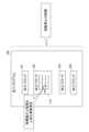
- FIG. 11 is a functional block diagram of a numerical control device 1A of a machine tool according to the modified example.
- the modified example differs from the above embodiment in that the machining state acquisition unit 12 of the numerical control device 1A acquires an index value indicating the machining state based on a signal from a sensor 30, but the other configurations are the same.
- the machining state acquisition unit 12 acquires an index value based on information acquired from the sensor 30.
- the machining state acquisition unit 12 can also use a combination of an index value calculated based on the machining conditions and the oscillation conditions and an index value based on information acquired from the sensor 30. In this way, the method of acquiring the index value is not limited to the configurations of the first and second embodiments.
- the machining state acquisition unit 12 of the numerical control device 1A of the modified machine tool described above acquires an index value based on the detection information of the sensor 30 that acquires information about the machining state. This makes it possible to determine whether or not to perform oscillation based on the index value based on the situation from the sensor 30 that indicates the actual situation, thereby enabling control that is more in line with the actual machining situation to be realized.
- the range is a range from a point (110) in the processing block (104) where the index value exceeds the upper limit value.
- the range of the swing stop is: In the entire machining program (100) made up of a plurality of machining blocks (101 to 104) constituting the plurality of machining blocks (102 to 104), the range is beyond the range of the machining block (102).
- a swing operation execution determination unit (15) that determines whether or not to execute a swing operation for swinging the cutting tool (T) and the workpiece (W) relatively based on the machining program (100),
- the rocking motion execution determination unit (15) If there is a point (110) in the machining program (100) composed of a plurality of machining blocks (101 to 104) where the index value exceeds the upper limit value, a swing stop range is set so that the swing operation is not performed throughout the entire machining program (100).
- the machining state acquisition unit (12) acquires the index value based on detection information of a sensor (30) that acquires information regarding the machining state.
- the apparatus further includes a condition acquisition unit (11) for acquiring processing conditions and swing conditions,
- the machining state acquisition unit (12) calculates an index value indicating the machining state from the machining conditions and the oscillation conditions acquired by the condition acquisition unit (11).
- the processing state acquisition unit (12) A chip length for acquiring the length of the chip of the workpiece (W); A surface roughness for acquiring the surface roughness of the workpiece (W); A swing frequency in the relative swing of the cutting tool (T) and the workpiece (W); A swing amplitude in the relative swing of the cutting tool (T) and the workpiece (W); a maximum speed in the relative oscillation of the cutting tool (T) and the workpiece (W); A maximum acceleration in the relative oscillation of the cutting tool (T) and the workpiece (W); A maximum jerk in the relative swing of the cutting tool (T) and the workpiece (W); One or more of the above is acquired as an index value.
Landscapes
- Engineering & Computer Science (AREA)
- Human Computer Interaction (AREA)
- Manufacturing & Machinery (AREA)
- Physics & Mathematics (AREA)
- General Physics & Mathematics (AREA)
- Automation & Control Theory (AREA)
- Numerical Control (AREA)
- Automatic Control Of Machine Tools (AREA)
Priority Applications (4)
| Application Number | Priority Date | Filing Date | Title |
|---|---|---|---|
| CN202380090414.5A CN120418741A (zh) | 2023-01-19 | 2023-01-19 | 机床的控制装置 |
| PCT/JP2023/001598 WO2024154314A1 (ja) | 2023-01-19 | 2023-01-19 | 工作機械の制御装置 |
| JP2024571557A JPWO2024154314A1 (https=) | 2023-01-19 | 2023-01-19 | |
| DE112023004634.4T DE112023004634T5 (de) | 2023-01-19 | 2023-01-19 | Steuerungsvorrichtung für Werkzeugmaschinen |
Applications Claiming Priority (1)
| Application Number | Priority Date | Filing Date | Title |
|---|---|---|---|
| PCT/JP2023/001598 WO2024154314A1 (ja) | 2023-01-19 | 2023-01-19 | 工作機械の制御装置 |
Publications (1)
| Publication Number | Publication Date |
|---|---|
| WO2024154314A1 true WO2024154314A1 (ja) | 2024-07-25 |
Family
ID=91955609
Family Applications (1)
| Application Number | Title | Priority Date | Filing Date |
|---|---|---|---|
| PCT/JP2023/001598 Ceased WO2024154314A1 (ja) | 2023-01-19 | 2023-01-19 | 工作機械の制御装置 |
Country Status (4)
| Country | Link |
|---|---|
| JP (1) | JPWO2024154314A1 (https=) |
| CN (1) | CN120418741A (https=) |
| DE (1) | DE112023004634T5 (https=) |
| WO (1) | WO2024154314A1 (https=) |
Citations (6)
| Publication number | Priority date | Publication date | Assignee | Title |
|---|---|---|---|---|
| JP2018180990A (ja) * | 2017-04-14 | 2018-11-15 | ファナック株式会社 | 揺動切削を行う工作機械の制御装置 |
| JP2019069494A (ja) * | 2017-10-11 | 2019-05-09 | ファナック株式会社 | 制御装置 |
| JP2020064359A (ja) * | 2018-10-15 | 2020-04-23 | ファナック株式会社 | 数値制御装置 |
| JP2020144588A (ja) * | 2019-03-06 | 2020-09-10 | ファナック株式会社 | 工作機械の制御装置 |
| JP2021066005A (ja) * | 2018-11-29 | 2021-04-30 | ファナック株式会社 | 数値制御装置、プログラム及び制御方法 |
| WO2022009925A1 (ja) * | 2020-07-10 | 2022-01-13 | ファナック株式会社 | 工作機械の制御装置 |
-
2023
- 2023-01-19 JP JP2024571557A patent/JPWO2024154314A1/ja active Pending
- 2023-01-19 DE DE112023004634.4T patent/DE112023004634T5/de active Pending
- 2023-01-19 CN CN202380090414.5A patent/CN120418741A/zh active Pending
- 2023-01-19 WO PCT/JP2023/001598 patent/WO2024154314A1/ja not_active Ceased
Patent Citations (6)
| Publication number | Priority date | Publication date | Assignee | Title |
|---|---|---|---|---|
| JP2018180990A (ja) * | 2017-04-14 | 2018-11-15 | ファナック株式会社 | 揺動切削を行う工作機械の制御装置 |
| JP2019069494A (ja) * | 2017-10-11 | 2019-05-09 | ファナック株式会社 | 制御装置 |
| JP2020064359A (ja) * | 2018-10-15 | 2020-04-23 | ファナック株式会社 | 数値制御装置 |
| JP2021066005A (ja) * | 2018-11-29 | 2021-04-30 | ファナック株式会社 | 数値制御装置、プログラム及び制御方法 |
| JP2020144588A (ja) * | 2019-03-06 | 2020-09-10 | ファナック株式会社 | 工作機械の制御装置 |
| WO2022009925A1 (ja) * | 2020-07-10 | 2022-01-13 | ファナック株式会社 | 工作機械の制御装置 |
Also Published As
| Publication number | Publication date |
|---|---|
| JPWO2024154314A1 (https=) | 2024-07-25 |
| CN120418741A (zh) | 2025-08-01 |
| DE112023004634T5 (de) | 2025-10-02 |
Similar Documents
| Publication | Publication Date | Title |
|---|---|---|
| JP7524230B2 (ja) | 数値制御工作機械で使用するための制御装置、および制御装置を含む工作機械 | |
| JP7252426B1 (ja) | 工作機械の制御装置及び工作機械の表示装置 | |
| US20200249650A1 (en) | Numerical control system | |
| JPWO1998041357A1 (ja) | 加工処理装置 | |
| CN105446270B (zh) | 机床的控制装置 | |
| US11347196B2 (en) | Controller of machine tool | |
| US20240272603A1 (en) | Information processing device, device for controlling machine tool, and non-transitory computer-readable medium storing a computer program | |
| CN111273610B (zh) | 机床 | |
| CN112068484B (zh) | 一种数控机床cnc系统的实时中断处理方法 | |
| JP7704866B2 (ja) | 工作機械の制御装置及び工作機械の制御システム | |
| CN112867975B (zh) | 维护辅助系统、数控装置及维护辅助系统的控制方法 | |
| WO2024154314A1 (ja) | 工作機械の制御装置 | |
| JP2019034345A (ja) | 工具異常検知装置および該方法 | |
| US20230037816A1 (en) | Control device for machine tool | |
| JP6919427B2 (ja) | 工作機械、工作機械の制御方法、及び、工作機械の制御プログラム | |
| US20250208601A1 (en) | Information processing device, machine tool control device, and non-transitory computer-readable medium storing a computer program | |
| JP7810783B2 (ja) | 加工面推定装置およびコンピュータ読み取り可能な記憶媒体 | |
| WO2024116336A1 (ja) | 工作機械の制御装置 | |
| JP7827878B2 (ja) | 工作機械の制御装置及び工作機械の表示装置 | |
| JP7799048B2 (ja) | 工作機械の制御装置 | |
| WO2024062607A1 (ja) | 工作機械の制御装置 | |
| JP7829684B2 (ja) | 工作機械の操作方法 | |
| JP2001138136A (ja) | ネジ切り加工制御装置 | |
| WO2024232103A1 (ja) | 工作機械の表示装置 | |
| WO2024116341A1 (ja) | 工作機械の制御装置 |
Legal Events
| Date | Code | Title | Description |
|---|---|---|---|
| 121 | Ep: the epo has been informed by wipo that ep was designated in this application |
Ref document number: 23917527 Country of ref document: EP Kind code of ref document: A1 |
|
| WWE | Wipo information: entry into national phase |
Ref document number: 112023004634 Country of ref document: DE |
|
| WWE | Wipo information: entry into national phase |
Ref document number: 202380090414.5 Country of ref document: CN |
|
| ENP | Entry into the national phase |
Ref document number: 2024571557 Country of ref document: JP Kind code of ref document: A |
|
| WWE | Wipo information: entry into national phase |
Ref document number: 2024571557 Country of ref document: JP |
|
| WWP | Wipo information: published in national office |
Ref document number: 202380090414.5 Country of ref document: CN |
|
| WWP | Wipo information: published in national office |
Ref document number: 112023004634 Country of ref document: DE |
|
| 122 | Ep: pct application non-entry in european phase |
Ref document number: 23917527 Country of ref document: EP Kind code of ref document: A1 |