WO2024154229A1 - 工作機械 - Google Patents
工作機械 Download PDFInfo
- Publication number
- WO2024154229A1 WO2024154229A1 PCT/JP2023/001172 JP2023001172W WO2024154229A1 WO 2024154229 A1 WO2024154229 A1 WO 2024154229A1 JP 2023001172 W JP2023001172 W JP 2023001172W WO 2024154229 A1 WO2024154229 A1 WO 2024154229A1
- Authority
- WO
- WIPO (PCT)
- Prior art keywords
- tool
- proximity sensor
- arm
- drawbar
- spindle
- Prior art date
- Legal status (The legal status is an assumption and is not a legal conclusion. Google has not performed a legal analysis and makes no representation as to the accuracy of the status listed.)
- Ceased
Links
Images



Classifications
-
- B—PERFORMING OPERATIONS; TRANSPORTING
- B23—MACHINE TOOLS; METAL-WORKING NOT OTHERWISE PROVIDED FOR
- B23Q—DETAILS, COMPONENTS, OR ACCESSORIES FOR MACHINE TOOLS, e.g. ARRANGEMENTS FOR COPYING OR CONTROLLING; MACHINE TOOLS IN GENERAL CHARACTERISED BY THE CONSTRUCTION OF PARTICULAR DETAILS OR COMPONENTS; COMBINATIONS OR ASSOCIATIONS OF METAL-WORKING MACHINES, NOT DIRECTED TO A PARTICULAR RESULT
- B23Q3/00—Devices holding, supporting, or positioning work or tools, of a kind normally removable from the machine
- B23Q3/12—Devices holding, supporting, or positioning work or tools, of a kind normally removable from the machine for securing to a spindle in general
-
- B—PERFORMING OPERATIONS; TRANSPORTING
- B23—MACHINE TOOLS; METAL-WORKING NOT OTHERWISE PROVIDED FOR
- B23Q—DETAILS, COMPONENTS, OR ACCESSORIES FOR MACHINE TOOLS, e.g. ARRANGEMENTS FOR COPYING OR CONTROLLING; MACHINE TOOLS IN GENERAL CHARACTERISED BY THE CONSTRUCTION OF PARTICULAR DETAILS OR COMPONENTS; COMBINATIONS OR ASSOCIATIONS OF METAL-WORKING MACHINES, NOT DIRECTED TO A PARTICULAR RESULT
- B23Q17/00—Arrangements for observing, indicating or measuring on machine tools
- B23Q17/002—Arrangements for observing, indicating or measuring on machine tools for indicating or measuring the holding action of work or tool holders
- B23Q17/003—Arrangements for observing, indicating or measuring on machine tools for indicating or measuring the holding action of work or tool holders by measuring a position
-
- B—PERFORMING OPERATIONS; TRANSPORTING
- B23—MACHINE TOOLS; METAL-WORKING NOT OTHERWISE PROVIDED FOR
- B23B—TURNING; BORING
- B23B31/00—Chucks; Expansion mandrels; Adaptations thereof for remote control
- B23B31/02—Chucks
- B23B31/10—Chucks characterised by the retaining or gripping devices or their immediate operating means
-
- B—PERFORMING OPERATIONS; TRANSPORTING
- B23—MACHINE TOOLS; METAL-WORKING NOT OTHERWISE PROVIDED FOR
- B23Q—DETAILS, COMPONENTS, OR ACCESSORIES FOR MACHINE TOOLS, e.g. ARRANGEMENTS FOR COPYING OR CONTROLLING; MACHINE TOOLS IN GENERAL CHARACTERISED BY THE CONSTRUCTION OF PARTICULAR DETAILS OR COMPONENTS; COMBINATIONS OR ASSOCIATIONS OF METAL-WORKING MACHINES, NOT DIRECTED TO A PARTICULAR RESULT
- B23Q3/00—Devices holding, supporting, or positioning work or tools, of a kind normally removable from the machine
- B23Q3/155—Arrangements for automatic insertion or removal of tools, e.g. combined with manual handling
- B23Q3/1552—Arrangements for automatic insertion or removal of tools, e.g. combined with manual handling parts of devices for automatically inserting or removing tools
- B23Q3/15526—Storage devices; Drive mechanisms therefor
- B23Q3/15534—Magazines mounted on the spindle
-
- B—PERFORMING OPERATIONS; TRANSPORTING
- B23—MACHINE TOOLS; METAL-WORKING NOT OTHERWISE PROVIDED FOR
- B23B—TURNING; BORING
- B23B2260/00—Details of constructional elements
- B23B2260/034—Drawbars
Definitions
- This disclosure relates to machine tools.
- a machine tool that clamps a tool placed in a predetermined position, and when necessary, releases the clamped tool and replaces it with another tool.
- the machine tool is equipped with a drawbar that is movable back and forth inside the spindle, and an arm that pushes the drawbar forward when changing tools.
- the drawbar is biased rearward by a spring inside the spindle. When the drawbar is pushed forward by the arm, the spring extends to unclamp the tool, and when the arm is released from its forward push, the drawbar moves rearward due to the biasing force of the spring and clamps the tool.
- the extension/retraction state of the drawbar is monitored to detect whether the tool is clamped to the spindle.
- the extension/retraction state of the drawbar is indirectly detected by a single sensor that is fixed in position relative to the spindle.
- the machine tool disclosed herein is a machine tool capable of replacing a tool to be clamped to a spindle, and includes a drawbar that is biased backward by a biasing member, and clamps the tool to the spindle by moving backward and unclamps the tool to the spindle by moving forward, an interlocking part that is connected to the drawbar and interlocks with the forward and backward movement of the drawbar, an arm that pushes in the interlocking part to move the drawbar forward against the biasing member, a proximity sensor that is fixed to either the arm or the interlocking part and switches its output between on and off depending on the distance between the arm and the interlocking part, and a determination unit that determines the clamped state of the tool based on the on/off state of the proximity sensor.
- FIG. 2 is a partial side view of the machine tool of the present embodiment.
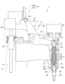
- FIG. 2 is a partial cross-sectional view showing a clamped state of a tool in the machine tool of the present embodiment.
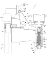
- FIG. 2 is a partial cross-sectional view showing an unclamped state of a tool in the machine tool of the present embodiment.
- FIG. 2 is an enlarged perspective view showing an interlocking part in the machine tool of the present embodiment.
- 5 is a front view of an interlocking part in the machine tool of the present embodiment, as viewed from the direction A in FIG. 4.
- 1 is a functional block diagram illustrating a configuration of a control device for a machine tool according to an embodiment of the present invention.
- FIG. 1 is a functional block diagram illustrating a configuration of a control device for a machine tool according to an embodiment of the present invention.
- FIG. 2 is a diagram illustrating a state where no tool is present in the machine tool of the present embodiment.
- 5A to 5C are diagrams illustrating a clamped state of a tool in the machine tool of the present embodiment.
- 5A to 5C are diagrams illustrating an unclamped state of a tool in the machine tool of the present embodiment.
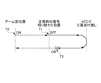
- 13A and 13B are diagrams illustrating the on/off state of the proximity sensor when a tool is normally replaced in the machine tool of the present embodiment.
- 13A to 13C are diagrams illustrating the on/off state of the proximity sensor when a tool is not replaced normally in the machine tool of the present embodiment.
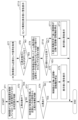
- 5 is a flowchart showing a determination process in the machine tool of the present embodiment.
- a machine tool 1 has a column 2, a spindle head 3, a spindle 4, a draw bar 5, an air injection unit 6, an arm 7, an automatic tool changer 8, a proximity sensor 9, and a control device 10 (see FIG. 7).
- the machine tool 1 is, for example, a machining center.
- the column 2 is a support for the machine tool 1 that extends in a direction substantially perpendicular to the work table (not shown). As shown in Figures 2 and 3, the column 2 has a translation shaft 21 disposed therein.
- the translation shaft 21 extends in the vertical direction inside the column 2.
- the translation shaft 21 is made up of, for example, a ball screw.
- the translation shaft 21 rotates around its axis by being driven by a translation shaft motor 20, which is made up of a servo motor provided at the upper end of the column 2.
- the spindle head 3 is supported on the column 2 so that it can move up and down.
- the spindle head 3 extends from the column 2 in a direction substantially perpendicular to the extension direction of the column 2.
- the spindle 4, which will be described later, is supported at the tip of the spindle head 3, which is far from the column 2.
- the base end of the spindle head 3, which is close to the column 2 is connected to the translation shaft 21 of the column 2. More specifically, as shown in Figures 2 and 3, the base end of the spindle head 3 is connected to a nut member 22 that screws onto the translation shaft 21.
- the spindle 4 is provided at the tip of the spindle head 3 so as to extend in the vertical direction.
- the spindle 4 is formed in a substantially cylindrical shape having a hollow portion 41 along the vertical direction.
- the spindle 4 is provided so as to be rotatable about an axis extending in the vertical direction by driving the spindle motor 40 shown in Figures 2 and 3.
- the machine tool 1 rotates the tool 80 clamped to the spindle 4 to machine a workpiece (not shown).
- the workpiece is attached to a rotating table (not shown) having a rotating shaft 200 (see Figure 6).
- the spindle 4 has a conical tool storage section 42 at its lower end, in which the hollow portion 41 expands in diameter downward.
- the tool storage section 42 stores the conical portion 82 at the upper end of the tool 80.
- the spindle 4 has a space portion 43 between the hollow portion 41 and the tool storage section 42, which is formed with a diameter larger than the inner diameter of the hollow portion 41.
- a cylindrical support portion 44 is provided that supports the drawbar 5 (described below).
- the drawbar 5 is disposed in the hollow portion 41 of the spindle 4 and is movable forward and backward within the spindle 4.
- the front and rear of the drawbar 5 are defined as follows.
- the "front” of the drawbar 5 is the side on which the tool 80 is disposed relative to the drawbar 5.
- the “rear” of the drawbar 5 is the side opposite the side on which the tool 80 is disposed relative to the drawbar 5.
- the front and rear of the drawbar 5 correspond to the bottom and top in the figure. Therefore, in the following description, the "front” will be expressed as “bottom” and the “rear” will be expressed as "top” in terms of the movement direction and biasing direction of the drawbar 5.
- the drawbar 5 has a drawbar main body 51, a tool gripping portion 52, and a biasing member 53.
- the drawbar body 51 extends vertically along the hollow portion 41 of the spindle 4.
- the drawbar body 51 is accommodated in the hollow portion 41 of the spindle 4 above the tool storage portion 42.
- the outer diameter of the drawbar body 51 is smaller than the inner diameter of the hollow portion 41 of the spindle 4. Therefore, a gap is formed between the inner surface of the hollow portion 41 of the spindle 4 and the outer surface of the drawbar body 51.
- the upper end of the drawbar body 51 is inserted into the support portion 44 of the spindle 4 so that it can move up and down.
- the drawbar body 51 has an air flow path 511 that extends vertically along the central axis (see Figures 7A, 7B, and 7C).
- the tool gripping portion 52 is integrally provided at the lower end of the drawbar body 51.
- the tool gripping portion 52 is formed with a diameter larger than the outer diameter of the drawbar body 51.
- the tool gripping portion 52 has a recess 521 that opens downward and accommodates a pull stud 81 provided at the upper end of the tool 80.
- a plurality of balls 522 are arranged in the circumferential direction on the peripheral surface of the lower end of the tool gripping portion 52 that forms the outer peripheral wall of the recess 521.
- the plurality of balls 522 are loosely attached to the tool gripping portion 52, so that they can move in the radial direction of the tool gripping portion 52.
- the lower end of the air flow path 511 of the drawbar body 51 is connected to the recess 521 of the tool gripping portion 52.
- the biasing member 53 is disposed in the gap between the inner surface of the hollow portion 41 of the spindle 4 and the outer surface of the drawbar body 51.
- the biasing member 53 is, for example, a coil spring.
- the biasing member 53 is provided so as to constantly bias the drawbar body 51 upward against the support portion 44 of the spindle 4.
- the air injection unit 6 is connected to the upper end of the drawbar 5.
- the air injection unit 6 is a metal cylinder and is arranged coaxially with the drawbar 5.
- an air injection passage 61 is provided inside the air injection unit 6.
- One end of the air injection passage 61 is connected to the upper end of the air passage 511 of the drawbar body 51.
- the air injection unit 6 is connected to an air supply source (not shown), and supplies air supplied from the air supply source to the air passage 511 of the drawbar body 51 via the air injection passage 61.
- the air supplied to the drawbar body 51 is sprayed into the recess 521 of the tool gripping portion 52. This cleans impurities attached to the recess 521 of the drawbar body 51 and the cone portion 82 of the tool 80.
- the air injection unit 6 also functions as a part that is pressed down by the arm 7, described below, when the tool 80 is replaced by the drawbar 5.
- the air injection unit 6 is disposed above the main shaft 4 and is connected to the upper end of the drawbar main body 51. Therefore, the air injection unit 6 is an interlocking part that is interlocked with the up and down movement of the drawbar 5.
- the air injection unit 6 is formed with a larger diameter than the main shaft 4.
- the upper end surface 62 of the air injection unit 6 is an annular flat surface.
- the upper end surface 62 of the air injection unit 6 is the surface that is pressed down by the arm 7, described below.
- the arm 7 has an arm body 71, a pivot shaft 72, a cam follower 63, and a pressing operation part 74.
- the arm body 71 is rotatably supported by a rotating shaft 72 on the upper part of the spindle head 3.
- the rotating shaft 72 extends in a direction perpendicular to the extension direction of the column 2 and perpendicular to the extension direction of the spindle head 3.
- the arm body 71 is formed in a roughly L-shape having a first arm portion 711 that extends from the rotating shaft 72 along the spindle head 3 toward the spindle 4, and a second arm portion 712 that extends upward from the rotating shaft 72.
- the arm body 71 is rotatable clockwise and counterclockwise in FIGS. 1 to 3 around the rotating shaft 72.
- the cam follower 73 is provided at the tip of the first arm portion 711 of the arm body 71.
- the cam follower 73 is, for example, formed of a cylindrical body.
- the cam follower 73 is rotatably provided on a rotation shaft 731 that is arranged parallel to the rotation shaft 72.
- the push-down operation unit 74 is provided at the tip of the second arm portion 712 of the arm body 71. As shown in Figs. 4 and 5, the push-down operation unit 74 has a pair of arms 741 arranged to sandwich the air injection unit 6 from both radial sides. As shown in Fig. 5, a cylindrical push-down member 742 is attached to each of the opposing inner surfaces of the pair of arms 741. The central axes of the push-down members 742 extend in opposing directions and are arranged at the same height from the upper end surface 62 of the air injection unit 6. The outer peripheral surface 742a of the push-down member 742 is arranged to face the upper end surface 62 of the air injection unit 6.
- a cam 23 is attached to the upper end of the column 2 above the spindle head 3.
- the cam 23 is provided at a position that protrudes from the column 2 toward the spindle 4.
- the cam 23 is composed of a plate-shaped member that extends along the extension direction of the column 2.
- the cam 23 has an inclined surface 231 that inclines toward the tip of the spindle head 3 as it extends upward, and a flat surface 232 that extends linearly in the vertical direction from the upper end of the inclined surface 231.
- the inclined surface 231 and the flat surface 232 are continuous vertically and form the cam surface of the cam 23.
- the cam follower 73 of the arm 7 is arranged to be able to slide on the cam 23 as the spindle head 3 moves up and down.
- the automatic tool changer (ATC) 8 is a disk-shaped device that holds multiple tools 80.
- the automatic tool changer 8 is rotatably attached to the machine tool 1 so that the tool attached to the spindle 4 can be replaced with the desired tool 80 depending on the work.
- the automatic tool changer 8 does not necessarily have to be provided on the machine tool 1.
- the tool 80 has, at its upper end, a pull stud 81 that is accommodated in the recess 521 of the tool gripping portion 52 of the drawbar 5, and a conical portion 82 that is provided below the pull stud 81.
- the conical portion 82 has a shape that matches the inner shape of the tool storage portion 42 of the spindle 4.
- the proximity sensor 9 is a sensor that detects the approach of an object without contact.
- the proximity sensor 9 has a coil that generates a high-frequency magnetic field, and when a detection object approaches the magnetic field, it detects a change in impedance due to an induced current flowing through the detection object. When the change in impedance detected by the approach of the detection object reaches a predetermined threshold, the proximity sensor 9 outputs an on/off signal to the control device 10 (see Figure 6).
- the proximity sensor 9 of this embodiment is fixed to the push-down operation part 74 of the arm 7. More specifically, as shown in Figs. 4 and 5, an L-shaped bracket 743 is attached to one arm 741 of the push-down operation part 74 of the arm 7. The proximity sensor 9 is attached to the bracket 743 and moves up and down together with the push-down operation part 74 of the arm 7. The proximity sensor 9 is attached to the bracket 743 and is positioned above the upper end surface 62 of the air injection part 6 so as to face the upper end surface 62. The lower surface of the proximity sensor 9 is positioned at the same position as the lower end of the push-down member 742 of the push-down operation part 74 and is spaced above the upper end surface 62 of the air injection part 6. The proximity sensor 9 detects whether the upper end surface 62 of the air injection part 6 has approached a predetermined distance using the upper end surface 62 of the air injection part 6 as a detection object.
- the proximity sensor 9 may output an ON signal when the upper end surface 62 of the air injection part 6 approaches a predetermined distance, or may output an OFF signal when the upper end surface 62 of the air injection part 6 approaches a predetermined distance.
- the proximity sensor 9 outputs an ON signal when it is a predetermined distance away from the upper end surface 62 of the air injection part 6, and outputs an OFF signal when it is a predetermined distance away from the upper end surface 62 of the air injection part 6.
- the predetermined distance is set to the distance D between the proximity sensor 9 and the upper end surface 62 of the air injection part 6 when the arm 7 is placed in a fixed position.
- the proximity sensor 9 is configured to be in an ON state when it is away from the upper end surface 62 of the air injection part 6 by more than the distance D, and to be in an OFF state when it is closer to the upper end surface 62 of the air injection part 6 by the distance D or less.
- FIG. 6 shows a functional block diagram of the control device 10.
- the control device 10 has a control unit 101, a determination unit 102, an acquisition unit 103, and a storage unit 104.
- the control device 10 may be provided in the machine tool 1, or may be provided in a numerical control device (not shown) that controls the operation of the machine tool 1.
- the control unit 101 controls various processes performed by the control device 10. Specifically, the control unit 101 controls the driving of the automatic tool changer 8, the translation axis motor 20, and the spindle motor 40 to perform clamping and unclamping operations of the tool 80 in the machine tool 1.
- the determination unit 102 compares the detection value of the timing of the on/off state change sent from the proximity sensor 9 with the normal value of the timing of the on/off state change that is preset in the memory unit 104. Based on the comparison result, the determination unit 102 determines whether there is an abnormality in the clamping of the tool 80 and an abnormality in the proximity sensor 9. The determination unit 102 also determines whether a tool is being changed by monitoring the signal for the control unit 101 to control the automatic tool changer 8. Furthermore, the determination unit 102 determines whether the movement amount of the arm 7 is normal from the movement amount of the arm 7 acquired by the means 12 for acquiring the arm movement amount described below.
- the acquisition unit 103 acquires an on/off signal from the proximity sensor 9 and outputs it to the determination unit 102.
- the memory unit 104 stores the normal value for the timing of switching the proximity sensor 9 between on and off to determine clamp abnormalities.
- the display unit 11 is, for example, a liquid crystal display device.
- the display unit 11 is connected to the control device 10 and displays various data sent from the control device 10 on the screen.
- the means 12 for acquiring the amount of arm movement is, for example, configured by an encoder provided on the rotation axis 72 of the arm 7.
- the means 12 for acquiring the amount of arm movement detects that the arm 7 has normally started to rotate from a fixed position to clamp and unclamp the tool 80, and that the arm 7 has normally returned to the fixed position.
- Whether the amount of arm movement is normal can be determined by comparing the amount of rotation of the arm 7 detected by the encoder with a normal value of the amount of rotation previously set in the memory unit 104. For example, if the amount of rotation of the arm 7 is within a predetermined threshold value of the normal value, the determination unit 102 determines that the amount of arm movement is normal.
- the means 12 for acquiring the amount of arm movement outputs the detection result to the acquisition unit 103.
- the main part of the control device 10 is composed of a processor.
- the memory is composed of a magnetic storage device, a semiconductor storage element such as a flash ROM (Read Only Memory), or other types of non-volatile storage device.
- the memory may include a RAM (Random Access Memory) that constitutes the work area of the processor.
- Each function of the control unit 101, judgment unit 102, and acquisition unit 103 of the control device 10 is realized by the processor executing, for example, specified software (programs, applications) stored in the memory.
- Figure 7A shows a state where no tool 80 is attached to the spindle 4.
- the arm 7 is positioned in a fixed position. That is, the arm 7 positions the push-down member 742 of the push-down operation unit 74 at the uppermost position.
- the drawbar 5 has moved to the uppermost position due to the upward biasing force of the biasing member 53.
- the upper end surface 62 of the air injection unit 6, which is linked to the drawbar 5, is positioned at position P0. This position P0 is equal to distance D, which is the predetermined distance at which the proximity sensor 9 switches between on and off states. Therefore, the proximity sensor 9 is in the off state.
- FIG. 7B shows the state in which the tool 80 is normally clamped to the spindle 4.
- the drawbar 5 moves upward due to the biasing force of the biasing member 53, and the pull stud 81 of the tool 80 housed in the recess 521 of the tool gripping portion 52 is gripped by the multiple balls 522, clamping the tool 80.
- the upward movement of the drawbar 5 is restricted by the conical portion 82 of the tool 80 abutting against the inner peripheral surface of the tool housing portion 42 of the spindle 4.
- the upper end surface 62 of the air injection portion 6 is located at position P1, which is lower than position P0. Therefore, when the arm 7 is returned to its home position, the proximity sensor 9 is in the ON state. In other words, the proximity sensor 9 being in the ON state when the arm 7 is in its home position indicates that the tool 80 is clamped to the spindle 4.
- FIG. 7C shows the state during attachment/detachment of the tool 80.
- the push member 742 of the push operation part 74 of the arm 7 pushes down the upper end surface 62 of the air injection part 6, causing the draw bar 5 to move to the lowest position against the biasing force of the biasing member 53.
- the multiple balls 522 provided in the tool gripping part 52 are positioned in the space 43 of the spindle 4.
- the multiple balls 522 move radially outward from the tool gripping part 52, and the tool 80 is in an unclamped state. Since the upper end surface 62 of the air injection part 6 is positioned at position P2, which is lower than position P1, the proximity sensor 9 is in an ON state when the arm 7 is returned to its home position.
- the pressing member 742 presses down the upper end surface 62 of the air injection part 6 until it is located at position P2, as shown in FIG. 7C.
- the proximity sensor 9 switches to the off state at timing T1 when it approaches the upper end surface 62 of the air injection part 6 within distance D.
- the upper end surface 62 of the air injection section 6 is positioned at position P1 as shown in FIG. 7B. This position P1 is lower than position P0. Therefore, as the arm 7 rotates toward the fixed position, the proximity sensor 9 switches back to the on state at timing T2 when the arm 7 is moved away from the upper end surface 62 of the air injection section 6 by more than the distance D.
- the tool 80 when the tool 80 is clamped, for example, if foreign matter is caught between the cone portion 82 of the tool 80 and the tool storage portion 42, the tool 80 is not clamped properly and is in a half-clamped state. In this case, even if the arm 7 returns to its fixed position and the draw bar 5 moves upward by the biasing force of the biasing member 53, the upper end surface 62 of the air injection portion 6 does not return to the position P1 shown in FIG. 7B where the tool 80 is clamped properly. Since the upward movement of the draw bar 5 is hindered by the caught foreign matter, the upper end surface 62 of the air injection portion 6 is positioned below the position P1.
- the proximity sensor 9 quickly moves away from the upper end surface 62 of the air injection portion 6 by more than the distance D. Therefore, as shown in FIG. 9, the time T1-T3 required from the timing T1 at which the proximity sensor 9 switches from the ON state to the OFF state to the timing T3 at which the proximity sensor 9 switches back to the ON state is shorter than the normal time T1-T2 shown in FIG. 8.
- the above-mentioned time T1-T2 which is the timing when the tool 80 is clamped normally, is stored as a normal value in the memory unit 104 of the control device 10.
- the determination unit 102 detects the timing of the switching of the on/off signal output from the proximity sensor 9 during a tool replacement operation, and compares it with the above-mentioned time T1-T2 stored as a normal value in the memory unit 104. If the determination unit 102 determines as a result of the comparison that the detected value is smaller than the normal value by more than a predetermined threshold value, it determines that an abnormal clamping of the tool 80 has occurred due to insufficient clamping.
- the push-down operation part 74 of the arm 7 presses down on the upper end surface 62 of the air injection part 6, causing the proximity sensor 9 to approach the upper end surface 62 and always turn off. Therefore, if the proximity sensor 9 does not transition to the off state during a tool changing operation, it can be determined that an abnormality such as a fault has occurred in the proximity sensor 9.
- the determination part 102 determines whether or not an abnormality has occurred in the proximity sensor 9 by judging whether or not the proximity sensor 9 has transitioned to the off state during a tool changing operation.
- the determination unit 102 of the control device 10 determines whether the control unit 101 is controlling the automatic tool changer 8 (step ST1). As a result, the determination unit 102 determines whether the machine tool 1 is changing tools (step ST2).
- step ST3 determines the presence or absence of the tool 80 on the spindle 4 from the signal of the proximity sensor 9 acquired by the acquisition unit 103 (step ST3). That is, when the spindle 4 clamps the tool 80, as shown in FIG. 7B, the upper end surface 62 of the air injection unit 6 is located at position P1, so that the proximity sensor 9 is in the ON state. The determination unit 102 determines whether the tool 80 is clamped on the spindle 4 from the state of the proximity sensor 9 acquired from the acquisition unit 103 (step ST4).
- step ST4 determines in step ST4 that the tool 80 is clamped on the spindle 4 (step ST4: YES)
- the determination unit 102 determines that the machining operation of the machine tool 1 can be performed, outputs a signal to that effect to the control unit 101, and ends the determination process.
- step ST4 determines in step ST4 that the tool 80 is not clamped to the spindle 4 (step ST4: NO)
- the determination unit 102 outputs a tool-absent signal to the control unit 101. This causes the control unit 101 to control the spindle 4, the translation axis 21, and the rotation axis 200 to stop (step ST5). After that, the control unit 101 displays a tool-absent warning on the display unit 11 (step ST6).
- step ST7 If the determination unit 102 determines in step ST2 above that the machine tool 1 is changing tools (step ST2: YES), it acquires the on/off signal of the proximity sensor 9 from the acquisition unit 103 (step ST7).
- the proximity sensor 9 always approaches the upper end surface 62 of the air injection unit 6 and outputs an off signal. Therefore, during tool change, the determination unit 102 monitors the signal of the proximity sensor 9 acquired from the acquisition unit 103, and determines whether or not there has been an off signal from the proximity sensor 9 (step ST8).
- step ST8 if the determination unit 102 determines that there is an off signal from the proximity sensor 9 (step ST8: YES), the determination unit 102 monitors the movement amount of the arm 7 acquired by the acquisition unit 103 from the means 12 for acquiring the arm movement amount and the timing of the on/off state switching of the proximity sensor 9, and determines whether these are normal (step ST9). That is, the determination unit 102 determines whether the movement amount of the arm 7 acquired from the means 12 for acquiring the arm movement amount is within the range of normal values set in the memory unit 104, and whether the detection value of the time of the timing of the on/off state switching of the proximity sensor 9 is within the range of normal values set in the memory unit 104 (step ST10).
- step ST10 if the judgment unit 102 judges that both the movement amount of the arm 7 and the switching timing of the proximity sensor 9 are normal (step ST10: YES), the judgment unit 102 judges that the tool 80 has been replaced normally and that the machining operation of the machine tool 1 can be performed, outputs a signal to that effect to the control unit 101, and ends the judgment process.
- step ST10 the determination unit 102 determines that at least one of the movement amount of the arm 7 and the switching timing of the proximity sensor 9 is abnormal (step ST10: NO). As a result, the determination unit 102 determines that the tool 80 is not clamped properly, and outputs a signal to that effect to the control unit 101.
- control unit 101 When the control unit 101 receives a signal from the determination unit 102 indicating that the tool 80 is not clamped properly, it stops the spindle 4, the translation axis 21, and the rotation axis 200 after the tool change operation is completed (step ST11). After that, the control unit 101 displays a warning on the display unit 11 indicating that the tool 80 is not clamped properly (step ST12).
- step ST8 determines in step ST8 above that there is no off signal from the proximity sensor 9 (step ST8: NO)
- the control unit 101 displays a warning of the abnormality in the proximity sensor 9 on the display unit 11.
- the proximity sensor 9 is fixed to the pressing operation part 74 of the arm 7 and is configured to switch between on and off states depending on the distance from the upper end surface 62 of the air injection part 6, but the proximity sensor 9 may also be configured to be fixed to the air injection part 6 and to switch between on and off states depending on the distance from the pressing operation part 74 of the arm 7.
- the machine tool 1 can detect the presence or absence of the tool 80 on the spindle 4 and the mis-clamped state of the tool 80 by using one proximity sensor 9 fixed to the arm 7. Therefore, it is possible to detect not only the presence or absence of the tool 80 on the spindle 4 but also the mis-clamped state of the tool 80 without increasing the number of sensors attached to the machine tool 1.
- the judgment unit 102 of the machine tool 1 judges whether or not there is a clamping abnormality in the tool 80 simply by comparing the detection value of the timing at which the proximity sensor 9 switches between on and off with a normal value. There is no need to perform complex arithmetic processing based on the detection value of the sensor. This simplifies the circuit configuration for the process of judging clamping abnormalities.
- the judgment unit 102 of the machine tool 1 judges whether or not there is an abnormality in the proximity sensor 9 based on the on/off state of the proximity sensor 9 during tool replacement, so there is no need to provide a separate configuration for judging an abnormality in the proximity sensor 9. This simplifies the circuit configuration for the abnormality judgment process of the proximity sensor 9.
- the machine tool (1) is a machine tool (1) capable of automatically replacing a tool (80) to be clamped to a spindle (4), and includes: a drawbar (5) that is urged upward by a urging member (53) and clamps the tool (80) to the spindle (4) by moving upward and unclamps the tool (80) to the spindle (4) by moving downward; an interlocking part (6) that is connected to the drawbar (5) and is interlocked with the up and down movement of the drawbar (5); an arm (7) that presses down the interlocking part (6) to move the drawbar (5) downward against the urging member (53); a proximity sensor (9) that is fixed to either the arm (7) or the interlocking part (6) and whose output is switched on/off depending on the distance between the arm (7) and the interlocking part (6); and a determination unit (102) that determines the clamped state of the tool (80) based on the
- the machine tool 1 of Appendix 1 is provided with a memory unit (104) that stores a normal value of the timing of switching the on/off state of the proximity sensor (9) during a tool changing operation, and the judgment unit (102) judges whether or not there is an abnormality in the clamping of the tool (80) based on a comparison result between a detection value of the timing of switching the on/off state of the proximity sensor (9) and the normal value stored in the memory unit (104).
- the judgment unit (102) judges the presence or absence of an abnormality in the proximity sensor (9) based on the on/off state of the proximity sensor (9) during tool change.
Landscapes
- Engineering & Computer Science (AREA)
- Mechanical Engineering (AREA)
- Machine Tool Sensing Apparatuses (AREA)
- Automatic Tool Replacement In Machine Tools (AREA)
Abstract
Description
(付記1)
工作機械(1)は、主軸(4)にクランプさせる工具(80)を自動で交換可能な工作機械(1)であって、付勢部材(53)によって上方に付勢され、上方への移動によって主軸(4)に対する工具(80)のクランプを行い、下方への移動によって主軸(4)に対する工具(80)のアンクランプを行うドローバ(5)、ドローバ(5)に接続され、ドローバ(5)の上下移動に連動する部品である連動部品(6)と、付勢部材(53)に抗してドローバ(5)を下方に移動させるために連動部品(6)を押し下げるアーム(7)と、アーム(7)及び連動部品(6)のいずれかに固定され、アーム(7)と連動部品(6)との間の距離に応じて出力がオン/オフで切り替わる近接センサ(9)と、近接センサ(9)のオン/オフ状態に基づいて、工具(80)のクランプ状態を判定する判定部(102)と、を備える。
付記1の工作機械1において、工具交換動作時の近接センサ(9)のオン/オフ状態の切り替わりのタイミングの正常値を記憶する記憶部(104)を備え、判定部(102)は、近接センサ(9)のオン/オフ状態の切り替わりのタイミングの検出値と、記憶部(104)に記憶された正常値と、の比較結果に基づいて、工具(80)のクランプ異常の有無を判定する。
付記1又は付記2に記載の工作機械1において、判定部(102)は、工具交換中の近接センサ(9)のオン/オフ状態に基づいて、近接センサ(9)の異常の有無を判定する。
4 主軸
5 ドローバ
6 エア注入部(連動部品)
7 アーム
9 近接センサ
80 工具
53 付勢部材
102 判定部
104 記憶部
Claims (3)
- 主軸にクランプさせる工具を交換可能な工作機械であって、
付勢部材によって後方に付勢され、後方への移動によって前記主軸に対する前記工具のクランプを行い、前方への移動によって前記主軸に対する前記工具のアンクランプを行うドローバと、
前記ドローバに接続され、前記ドローバの前後移動に連動する連動部品と、
前記付勢部材に抗して前記ドローバを前方に移動させるために前記連動部品を前方に向けて押し込むアームと、
前記アーム及び前記連動部品のいずれかに固定され、前記アームと前記連動部品との間の距離に応じて出力がオン/オフで切り替わる近接センサと、
前記近接センサのオン/オフ状態に基づいて、前記工具のクランプ状態を判定する判定部と、
を備える工作機械。 - 前記工具交換動作時の前記近接センサのオン/オフ状態の切り替わりのタイミングの正常値を記憶する記憶部を備え、
前記判定部は、前記近接センサのオン/オフ状態の切り替わりのタイミングの検出値と、前記記憶部に記憶された前記正常値と、の比較結果に基づいて、前記工具のクランプ異常の有無を判定する、請求項1に記載の工作機械。 - 前記判定部は、前記工具交換中の前記近接センサのオン/オフ状態に基づいて、前記近接センサの異常の有無を判定する、請求項1又は2に記載の工作機械。
Priority Applications (5)
| Application Number | Priority Date | Filing Date | Title |
|---|---|---|---|
| DE112023004616.6T DE112023004616T5 (de) | 2023-01-17 | 2023-01-17 | Werkzeugmaschine |
| JP2024571477A JPWO2024154229A1 (ja) | 2023-01-17 | 2023-01-17 | |
| KR1020257017645A KR20250095722A (ko) | 2023-01-17 | 2023-01-17 | 공작 기계 |
| CN202380090583.9A CN120418028A (zh) | 2023-01-17 | 2023-01-17 | 机床 |
| PCT/JP2023/001172 WO2024154229A1 (ja) | 2023-01-17 | 2023-01-17 | 工作機械 |
Applications Claiming Priority (1)
| Application Number | Priority Date | Filing Date | Title |
|---|---|---|---|
| PCT/JP2023/001172 WO2024154229A1 (ja) | 2023-01-17 | 2023-01-17 | 工作機械 |
Publications (1)
| Publication Number | Publication Date |
|---|---|
| WO2024154229A1 true WO2024154229A1 (ja) | 2024-07-25 |
Family
ID=91955530
Family Applications (1)
| Application Number | Title | Priority Date | Filing Date |
|---|---|---|---|
| PCT/JP2023/001172 Ceased WO2024154229A1 (ja) | 2023-01-17 | 2023-01-17 | 工作機械 |
Country Status (5)
| Country | Link |
|---|---|
| JP (1) | JPWO2024154229A1 (ja) |
| KR (1) | KR20250095722A (ja) |
| CN (1) | CN120418028A (ja) |
| DE (1) | DE112023004616T5 (ja) |
| WO (1) | WO2024154229A1 (ja) |
Citations (5)
| Publication number | Priority date | Publication date | Assignee | Title |
|---|---|---|---|---|
| JP2002052406A (ja) * | 2000-05-31 | 2002-02-19 | Ntn Corp | 自動工具交換機能付きスピンドル装置 |
| JP2005028534A (ja) * | 2003-07-09 | 2005-02-03 | Okuma Corp | 工作機械のドローバー位置検出機構 |
| JP2018065229A (ja) * | 2016-10-21 | 2018-04-26 | 株式会社スギノマシン | 主軸装置、および工作機械 |
| JP2018167377A (ja) * | 2017-03-30 | 2018-11-01 | ファナック株式会社 | 工作機械 |
| JP2021103395A (ja) * | 2019-12-25 | 2021-07-15 | ブラザー工業株式会社 | 数値制御装置、制御方法、及び記憶媒体 |
Family Cites Families (1)
| Publication number | Priority date | Publication date | Assignee | Title |
|---|---|---|---|---|
| JP5136091B2 (ja) | 2008-01-30 | 2013-02-06 | ブラザー工業株式会社 | 数値制御装置 |
-
2023
- 2023-01-17 WO PCT/JP2023/001172 patent/WO2024154229A1/ja not_active Ceased
- 2023-01-17 KR KR1020257017645A patent/KR20250095722A/ko active Pending
- 2023-01-17 CN CN202380090583.9A patent/CN120418028A/zh active Pending
- 2023-01-17 JP JP2024571477A patent/JPWO2024154229A1/ja active Pending
- 2023-01-17 DE DE112023004616.6T patent/DE112023004616T5/de active Pending
Patent Citations (5)
| Publication number | Priority date | Publication date | Assignee | Title |
|---|---|---|---|---|
| JP2002052406A (ja) * | 2000-05-31 | 2002-02-19 | Ntn Corp | 自動工具交換機能付きスピンドル装置 |
| JP2005028534A (ja) * | 2003-07-09 | 2005-02-03 | Okuma Corp | 工作機械のドローバー位置検出機構 |
| JP2018065229A (ja) * | 2016-10-21 | 2018-04-26 | 株式会社スギノマシン | 主軸装置、および工作機械 |
| JP2018167377A (ja) * | 2017-03-30 | 2018-11-01 | ファナック株式会社 | 工作機械 |
| JP2021103395A (ja) * | 2019-12-25 | 2021-07-15 | ブラザー工業株式会社 | 数値制御装置、制御方法、及び記憶媒体 |
Also Published As
| Publication number | Publication date |
|---|---|
| CN120418028A (zh) | 2025-08-01 |
| KR20250095722A (ko) | 2025-06-26 |
| DE112023004616T5 (de) | 2025-09-11 |
| JPWO2024154229A1 (ja) | 2024-07-25 |
Similar Documents
| Publication | Publication Date | Title |
|---|---|---|
| US7217229B2 (en) | Apparatus for automatically changing a robot tool tip member | |
| JP5851078B1 (ja) | タレット刃物台及びこれを備えた工作機械 | |
| US8215214B2 (en) | Workpiece gripping method and workpiece centering apparatus | |
| CN107791094A (zh) | 流体喷射装置 | |
| US11376685B2 (en) | Automatic tip changer for burnback in an arc welding robot | |
| KR101931776B1 (ko) | 치과용 밀링 머신의 공구 파손 감지 방법 | |
| WO2024154229A1 (ja) | 工作機械 | |
| TW202306692A (zh) | 車床、及其切斷車刀破損檢測方法 | |
| JP6297128B1 (ja) | 工作機械 | |
| JP6484273B2 (ja) | 工作機械 | |
| KR102536393B1 (ko) | 공작기계의 스핀들 장치 | |
| JP2003260638A (ja) | 工作機械のツールクランプ異常検知装置 | |
| KR20190070203A (ko) | 치과용 밀링 머신 및 그 구동 방법 | |
| JPWO2020079756A1 (ja) | 自動工具交換機 | |
| TWI809223B (zh) | 車床 | |
| JPH05318291A (ja) | 予備工具の取換方法 | |
| KR101543805B1 (ko) | 선삭가공용 공작물의 절단 확인 장치 | |
| JPH02243252A (ja) | 工作機械におけるツールホルダの取付不良検出装置 | |
| KR101401128B1 (ko) | 자동 공구 교환 장치의 공구 파손 방지용 안전 장치 | |
| JP2006088299A (ja) | タッピング装置 | |
| JP3572270B2 (ja) | 連続ローディング装置 | |
| JP2017154206A (ja) | 工作機械、工作機械のノズル制御方法及びコンピュータプログラム | |
| JPS6126448B2 (ja) | ||
| KR20100061905A (ko) | 공작기계의 공구 파손 검출 장치 | |
| JP2003080409A (ja) | 工作機械の主軸装置 |
Legal Events
| Date | Code | Title | Description |
|---|---|---|---|
| 121 | Ep: the epo has been informed by wipo that ep was designated in this application |
Ref document number: 23917443 Country of ref document: EP Kind code of ref document: A1 |
|
| ENP | Entry into the national phase |
Ref document number: 20257017645 Country of ref document: KR Kind code of ref document: A |
|
| WWP | Wipo information: published in national office |
Ref document number: 1020257017645 Country of ref document: KR |
|
| WWE | Wipo information: entry into national phase |
Ref document number: 112023004616 Country of ref document: DE |
|
| WWE | Wipo information: entry into national phase |
Ref document number: 202380090583.9 Country of ref document: CN |
|
| WWE | Wipo information: entry into national phase |
Ref document number: 202547064946 Country of ref document: IN |
|
| ENP | Entry into the national phase |
Ref document number: 2024571477 Country of ref document: JP Kind code of ref document: A |
|
| WWE | Wipo information: entry into national phase |
Ref document number: 2024571477 Country of ref document: JP |
|
| WWP | Wipo information: published in national office |
Ref document number: 202547064946 Country of ref document: IN |
|
| WWP | Wipo information: published in national office |
Ref document number: 202380090583.9 Country of ref document: CN |
|
| WWP | Wipo information: published in national office |
Ref document number: 112023004616 Country of ref document: DE |
|
| 122 | Ep: pct application non-entry in european phase |
Ref document number: 23917443 Country of ref document: EP Kind code of ref document: A1 |