WO2024150751A1 - 動作制御装置、および入力装置 - Google Patents
動作制御装置、および入力装置 Download PDFInfo
- Publication number
- WO2024150751A1 WO2024150751A1 PCT/JP2024/000226 JP2024000226W WO2024150751A1 WO 2024150751 A1 WO2024150751 A1 WO 2024150751A1 JP 2024000226 W JP2024000226 W JP 2024000226W WO 2024150751 A1 WO2024150751 A1 WO 2024150751A1
- Authority
- WO
- WIPO (PCT)
- Prior art keywords
- movable member
- detection surface
- functions
- finger
- input device
- Prior art date
- Legal status (The legal status is an assumption and is not a legal conclusion. Google has not performed a legal analysis and makes no representation as to the accuracy of the status listed.)
- Ceased
Links
Images



Classifications
-
- B—PERFORMING OPERATIONS; TRANSPORTING
- B60—VEHICLES IN GENERAL
- B60R—VEHICLES, VEHICLE FITTINGS, OR VEHICLE PARTS, NOT OTHERWISE PROVIDED FOR
- B60R16/00—Electric or fluid circuits specially adapted for vehicles and not otherwise provided for; Arrangement of elements of electric or fluid circuits specially adapted for vehicles and not otherwise provided for
- B60R16/02—Electric or fluid circuits specially adapted for vehicles and not otherwise provided for; Arrangement of elements of electric or fluid circuits specially adapted for vehicles and not otherwise provided for electric constitutive elements
-
- B—PERFORMING OPERATIONS; TRANSPORTING
- B62—LAND VEHICLES FOR TRAVELLING OTHERWISE THAN ON RAILS
- B62D—MOTOR VEHICLES; TRAILERS
- B62D1/00—Steering controls, i.e. means for initiating a change of direction of the vehicle
- B62D1/02—Steering controls, i.e. means for initiating a change of direction of the vehicle vehicle-mounted
- B62D1/04—Hand wheels
-
- B—PERFORMING OPERATIONS; TRANSPORTING
- B62—LAND VEHICLES FOR TRAVELLING OTHERWISE THAN ON RAILS
- B62D—MOTOR VEHICLES; TRAILERS
- B62D1/00—Steering controls, i.e. means for initiating a change of direction of the vehicle
- B62D1/02—Steering controls, i.e. means for initiating a change of direction of the vehicle vehicle-mounted
- B62D1/04—Hand wheels
- B62D1/08—Spokes, e.g. resilient
-
- G—PHYSICS
- G06—COMPUTING OR CALCULATING; COUNTING
- G06F—ELECTRIC DIGITAL DATA PROCESSING
- G06F3/00—Input arrangements for transferring data to be processed into a form capable of being handled by the computer; Output arrangements for transferring data from processing unit to output unit, e.g. interface arrangements
- G06F3/01—Input arrangements or combined input and output arrangements for interaction between user and computer
- G06F3/03—Arrangements for converting the position or the displacement of a member into a coded form
- G06F3/033—Pointing devices displaced or positioned by the user, e.g. mice, trackballs, pens or joysticks; Accessories therefor
- G06F3/0338—Pointing devices displaced or positioned by the user, e.g. mice, trackballs, pens or joysticks; Accessories therefor with detection of limited linear or angular displacement of an operating part of the device from a neutral position, e.g. isotonic or isometric joysticks
-
- G—PHYSICS
- G06—COMPUTING OR CALCULATING; COUNTING
- G06F—ELECTRIC DIGITAL DATA PROCESSING
- G06F3/00—Input arrangements for transferring data to be processed into a form capable of being handled by the computer; Output arrangements for transferring data from processing unit to output unit, e.g. interface arrangements
- G06F3/01—Input arrangements or combined input and output arrangements for interaction between user and computer
- G06F3/03—Arrangements for converting the position or the displacement of a member into a coded form
- G06F3/033—Pointing devices displaced or positioned by the user, e.g. mice, trackballs, pens or joysticks; Accessories therefor
- G06F3/0362—Pointing devices displaced or positioned by the user, e.g. mice, trackballs, pens or joysticks; Accessories therefor with detection of one-dimensional [1D] translations or rotations of an operating part of the device, e.g. scroll wheels, sliders, knobs, rollers or belts
-
- G—PHYSICS
- G06—COMPUTING OR CALCULATING; COUNTING
- G06F—ELECTRIC DIGITAL DATA PROCESSING
- G06F3/00—Input arrangements for transferring data to be processed into a form capable of being handled by the computer; Output arrangements for transferring data from processing unit to output unit, e.g. interface arrangements
- G06F3/01—Input arrangements or combined input and output arrangements for interaction between user and computer
- G06F3/048—Interaction techniques based on graphical user interfaces [GUI]
- G06F3/0481—Interaction techniques based on graphical user interfaces [GUI] based on specific properties of the displayed interaction object or a metaphor-based environment, e.g. interaction with desktop elements like windows or icons, or assisted by a cursor's changing behaviour or appearance
- G06F3/0482—Interaction with lists of selectable items, e.g. menus
-
- H—ELECTRICITY
- H01—ELECTRIC ELEMENTS
- H01H—ELECTRIC SWITCHES; RELAYS; SELECTORS; EMERGENCY PROTECTIVE DEVICES
- H01H23/00—Tumbler or rocker switches, i.e. switches characterised by being operated by rocking an operating member in the form of a rocker button
-
- H—ELECTRICITY
- H01—ELECTRIC ELEMENTS
- H01H—ELECTRIC SWITCHES; RELAYS; SELECTORS; EMERGENCY PROTECTIVE DEVICES
- H01H25/00—Switches with compound movement of handle or other operating part
- H01H25/04—Operating part movable angularly in more than one plane, e.g. joystick
Definitions
- This disclosure relates to an operation control device having an input device for controlling the operation of a controlled device. This disclosure also relates to the input device.
- JP Patent Publication No. 2015-170119 discloses a steering device mounted on a vehicle as an example of an operation control device.
- the steering device has a steering member that changes the traveling direction of the vehicle by rotating around a rotation axis.
- An input device is installed on the steering member.
- the input device has a rotating member that can rotate around a rotation axis that extends along the rotation radius direction.
- a display device mounted on the vehicle displays a menu showing multiple operations of controlled devices that can be executed on the vehicle. The driver can select a desired one from the menu by rotating the rotating member.
- a motion control device comprising: a shaft portion that is rotatable about a rotation axis, the rotation being associated with a first controlled action; A grip portion that can be rotated along a rotation path centered on the rotation axis and can be held by a user's hand; an input device disposed between the shaft portion and the grip portion; Equipped with The input device is A movable member that is displaceable in a first direction along a turning radius of the gripping portion; A detection surface is disposed on the movable member so as to be elongated in a second direction along the pivot path, and detects contact or approach of a finger of the user; Equipped with A movement of the finger on the detection surface in the second direction is associated with an operation of selecting one of a plurality of functions, Displacement of the movable member in the first direction is associated with a second controlled action associated with a selected one of the plurality of functions.
- a motion control device including a shaft portion that is rotatable about a rotation axis, the rotation being associated with a first controlled motion, and a grip portion that is rotatable along a rotation path about the rotation axis and that can be held by a user's hand, the motion control device including an input device disposed between the shaft portion and the grip portion, a movable member disposed on the motion control device so as to be displaceable in a first direction along a turning radius of the gripping portion; A detection surface is disposed on the movable member so as to be elongated in a second direction along the pivot path, and detects contact or approach of a finger of the user; Equipped with A movement of the finger on the detection surface in the second direction is associated with an operation of selecting one of a plurality of functions, Displacement of the movable member in the first direction is associated with a second controlled action associated with a selected one of the plurality of functions.
- the first and second operations are performed by the user's fingers (typically the thumb) holding the grip. Since the detection surface is disposed so as to be long in the second direction along the rotation direction of the grip, the user can perform the first operation with a long stroke without bending the joints of the fingers.
- the greater the number of functions available for selection the greater the advantage of being able to extend the stroke of the first operation. This is because the number of options that can be covered with one operation increases. In other words, one can be selected from a greater number of functions with an operation that places less strain on the fingers.
- the second operation for executing a second controlled action associated with one of the selected functions is performed by displacing the movable member in a first direction intersecting the second direction, thereby enhancing the distinguishability between the first and second operations. This advantage is more pronounced when multiple controlled actions that need to be selected are associated with each function.
- FIG. 1 illustrates a vehicle equipped with a steering device according to an embodiment.
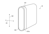
- 2 illustrates an example of the appearance of an input device mounted on the steering device of FIG. 1 .
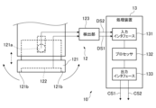
- 3 illustrates an example of a functional configuration of the steering device of FIG. 2 .
- 2 shows an example of the operation of the steering device of FIG. 1 .
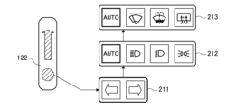
- 4 shows another example of the operation of the steering device of FIG. 1 .
- 4 shows another example of the operation of the steering device of FIG. 1 .
- FIG. 1 illustrates an example of a cabin of a vehicle 20 equipped with a steering device 10 according to one embodiment.
- the steering device 10 is a device for causing the vehicle 20 to perform an operation to change the traveling direction.
- the steering device 10 is an example of a motion control device.
- the operation to change the traveling direction is an example of a first controlled operation.
- the vehicle 20 is an example of a moving body.
- the steering device 10 includes a steering member 11.
- the steering member 11 has a shaft portion 111 and a grip portion 112.
- the shaft portion 111 is configured to be rotatable around a rotation axis A.
- the grip portion 112 is configured to be gripped by the driver's hand.
- the driver is an example of a user.
- the grip portion 112 is configured to be rotatable along a rotation path P centered on the rotation axis A.
- the grip portion 112 rotates in the same direction.
- the direction of rotation corresponds to the changed traveling direction of the vehicle 20.
- the steering device 10 is equipped with an input device 12.
- the input device 12 is disposed between the shaft portion 111 and the grip portion 112.
- the input device 12 includes a movable member 121.
- the movable member 121 is configured to be displaceable in a first direction D1 along the turning radius R of the grip portion 112.
- the movable member 121 is configured to be operated by the fingers of the driver holding the grip portion 112.
- the movable member 121 is configured to be rotatable about a rotation axis 121a extending in a second direction D2 along the rotation path P of the gripping portion 112.
- a rotation axis 121a extending in a second direction D2 along the rotation path P of the gripping portion 112.
- the movable member 121 rotates in the clockwise direction in FIG. 3, it is displaced in a direction corresponding to the inside of the rotation radius R.
- the movable member 121 rotates in the counterclockwise direction in FIG. 3, it is displaced in a direction corresponding to the outside of the rotation radius R.
- the input device 12 includes a detection surface 122 and a detection unit 123.
- the detection surface 122 is disposed on the movable member 121 so as to be elongated in a second direction D2 along the rotation direction of the grip unit 112.
- the detection unit 123 is configured to detect contact or approach of the driver's fingers with the detection surface 122.
- the detection unit 123 is configured to detect a change in capacitance on the detection surface 122 that accompanies contact or approach of the driver's finger, and output a first detection signal DS1 indicating that the driver's finger has contacted or approached the detection surface 122 based on the change.
- the detection unit 123 is configured to detect a pressure change or displacement on the detection surface 122 caused by contact with the driver's fingers, and output a first detection signal DS1 indicating that the driver's fingers have contacted the detection surface 122 based on the pressure change or displacement.
- the first detection signal DS1 is configured to include information indicating the position on the detection surface where the driver's finger touches or approaches.
- the first detection signal DS1 may be an analog signal or a digital signal depending on the specifications of the input device 12.
- the detection unit 123 is also configured to detect the displacement of the movable member 121 in the first direction D1.
- the displacement of the movable member 121 can be detected mechanically, electrically, optically, or magnetically using a well-known sensor.
- the detection unit 123 is configured to output a second detection signal DS2 corresponding to the detected displacement direction of the movable member 121.
- the second detection signal DS2 may be an analog signal or a digital signal depending on the specifications of the sensor.
- the steering device 10 is equipped with a processing device 13.
- the processing device 13 may be built into the input device 12, or may be provided in an appropriate position independent of the input device 12.
- the processing device 13 includes an input interface 131.
- the input interface 131 is configured as a hardware interface that receives the first detection signal DS1 and the second detection signal DS2.
- the input interface 131 includes an appropriate conversion circuit including an A/D converter that converts the analog signal into a digital signal.
- the processing device 13 includes a processor 132 and an output interface 133.
- the processor 132 is configured to output a first control signal CS1 from the output interface 133 in response to the first detection signal DS1.
- the first control signal CS1 is associated with a first operation for selecting one of a plurality of functions executable in the vehicle 20.
- the plurality of functions includes at least a turn indication function.
- the turn indication function is a function for turning on a turn signal light to indicate a change in the traveling direction of the vehicle 20.
- the processor 132 is configured to output a second control signal CS2 from the output interface 133 in response to the second detection signal DS2.
- the second control signal CS2 is associated with a second operation for performing a controlled action associated with one of the selected functions.
- the turn indication function is selected, turning on the left turn indicator light and turning on the right turn indicator light can each be an example of a second controlled action.
- the output interface 133 is configured as a hardware interface that outputs the first control signal CS1 and the second control signal CS2.
- Each of the first control signal CS1 and the second control signal CS2 may be an analog signal or a digital signal depending on the specifications of the device that processes the signal.
- the output interface 133 is provided with an appropriate conversion circuit including a D/A converter.
- the vehicle 20 is equipped with a display device 21.
- the display device 21 is disposed to the right of the steering device 10.
- the display device 21 may be installed in a center cluster located in the center of the front of the vehicle 20.
- the display device 21 may be a head-up display device that projects an image onto the windshield of the vehicle 20.
- the display device 21 is a general-purpose display device capable of displaying screens corresponding to various applications executed in the vehicle 20.
- FIG. 4 illustrates an example in which the driver's fingers contact or approach a position near the upper end of the detection surface 122 of the input device 12.
- a direction indication function group image 211 a lamp control function group image 212
- a visibility improvement function group image 213 are displayed on the display device 21.
- the lamp control function group image 212 is displayed below the direction indication function group image 211.
- the visibility improvement function group image 213 is displayed below the lamp control function group image 212.
- an icon image associated with the operation of turning on the left direction indicator light and an icon image associated with the operation of turning on the right direction indicator light are arranged in the left-right direction.
- icon images associated with an operation to enable the automatic control function of the lamp are arranged in the left-right direction.
- the operation of the in-vehicle device associated with each icon image is an example of a second controlled operation.
- icon images associated with appropriate operations related to the lamp control function may be included in the lamp control function group image 212.
- icon images associated with an operation to enable the automatic control function of the wiper operation an icon image associated with an operation to operate the wipers intermittently, an icon image associated with an operation to spray cleaning fluid toward the windshield, and an icon image associated with an operation to turn on the anti-fogging heater are arranged in the left-right direction.
- the operation of the in-vehicle device associated with each icon image is an example of a second controlled operation.
- icon images associated with appropriate operations related to the visibility improvement function may be included in the visibility improvement function group image 213.
- the processing device 13 In response to the first detection signal DS1 that is received first, the processing device 13 outputs a first control signal CS1 that controls the display device 21 to indicate that the direction indication function group image 211 is selected.
- the movable member 121 When the driver wishes to change course to the left, the movable member 121 is displaced to the left in FIG. 3 (the direction corresponding to the inside of the turning radius R in FIG. 1) by the driver's finger. In response to a second detection signal DS2 corresponding to that displacement, the processing device 13 outputs a second control signal CS2 corresponding to the operation of turning on the left turn signal light.
- the movable member 121 When the driver wishes to change course to the right, the movable member 121 is displaced to the right in FIG. 3 (the direction corresponding to the outside of the turning radius R in FIG. 1) by the driver's finger. In response to a second detection signal DS2 corresponding to that displacement, the processing device 13 outputs a second control signal CS2 corresponding to the operation of turning on the right turn signal light.
- a first detection signal DS1 corresponding to that movement is output by the detection unit 123.
- the processing device 13 outputs a first control signal CS1 that controls the display device 21 to indicate that the lamp control function group image 212 located below the direction indication function group image 211 has been selected.
- an icon image associated with an operation to activate the automatic lamp control function is in a selected state.
- a second detection signal DS2 corresponding to the displacement is output from the detection unit 123.
- the processing device 13 In response to the second detection signal DS2 corresponding to the displacement, the processing device 13 outputs a second control signal CS2 that controls the display device 21 to select an icon image located to the left or right of the currently selected icon image in the lamp control function group image 212.
- the movable member 121 can also be displaced in a direction along the normal to the detection surface 122.
- the operation that brings about this displacement can be performed in order to determine the selection state of the icon image.
- This displacement can also be detected mechanically, electrically, optically, or magnetically by the detection unit 123 using a well-known sensor.
- the detection unit 123 outputs a second detection signal DS2 that corresponds to this displacement. Note that when the selection state of a certain icon image continues for a predetermined length of time, the selection state of the icon image can be determined.
- the processing device 13 When the selection state of a specific icon image included in the lighting control function group image 212 is confirmed, the processing device 13 outputs a second control signal CS2 that causes the controlled device to execute the operation associated with that icon image.
- a first detection signal DS1 corresponding to that movement is output by the detection unit 123.
- the processing device 13 outputs a first control signal CS1 that controls the display device 21 to indicate that the visibility improvement function group image 213 located below the lamp control function group image 212 has been selected.
- an icon image associated with an operation to activate the automatic control function of the wiper operation is in a selected state.
- a second detection signal DS2 corresponding to the displacement is output from the detection unit 123.
- the processing device 13 outputs a second control signal CS2 that controls the display device 21 to select an icon image located to the left or right of the icon image currently selected in the visibility improvement function group image 213.
- the processing device 13 When the selection state of a specific icon image included in the visibility improvement function group image 213 is confirmed, the processing device 13 outputs a second control signal CS2 that causes the controlled device to execute the operation associated with that icon image.
- the movement of the driver's finger on the detection surface 122 of the input device 12 in the second direction D2 is associated with a first operation for selecting one of a plurality of functions executable in the vehicle 20.
- the displacement of the movable member 121 of the input device 12 in the first direction D1 is associated with a second operation for executing a controlled action associated with one of the selected plurality of functions.
- the input device 12 is disposed between the shaft portion 111 and the grip portion 112 of the steering member 11, so that the first and second operations are performed by the fingers (generally the thumb) of the driver gripping the grip portion 112.
- the detection surface 122 is disposed so as to be long in the second direction D2 along the turning direction of the grip portion 112, so that the driver can perform the first operation with a long stroke without bending the joints of his or her fingers.
- the greater the number of functions available for selection the greater the advantage of being able to extend the stroke of the first operation. This is because the number of options that can be covered with one operation increases. In other words, one can be selected from a greater number of functions with an operation that places less strain on the fingers.
- the second operation for executing a controlled action associated with one of the selected functions is performed by displacing the movable member 121 in the first direction D1 intersecting the second direction D2, which enhances the distinguishability between the first operation and the second operation. This advantage is more pronounced when multiple controlled actions that need to be selected are associated with each function.
- FIG. 5 illustrates an example in which the driver's finger touches or approaches a position near the center of the detection surface 122 of the input device 12.
- the lamp control function group image 212 is displayed above the direction indication function group image 211.
- the visibility improvement function group image 213 is displayed below the direction indication function group image 211.
- the processing device 13 in response to the first detection signal DS1 that is received first, the processing device 13 outputs a first control signal CS1 that controls the display device 21 to indicate that the direction indication function group image 211 is selected.
- the subsequent operation using the movable member 121 is the same as that described with reference to FIG. 4, so a repeated description will be omitted.
- a first detection signal DS1 corresponding to that movement is output by the detection unit 123.
- the processing device 13 outputs a first control signal CS1 that controls the display device 21 to indicate that the lamp control function group image 212 located above the direction indication function group image 211 is selected.
- the subsequent operation using the movable member 121 is the same as that described with reference to FIG. 4, so repeated description will be omitted.
- a first detection signal DS1 corresponding to the movement is output by the detection unit 123.
- the processing device 13 outputs a first control signal CS1 that controls the display device 21 to indicate that the visibility improvement function group image 213 located below the direction indication function group image 211 is selected.
- the subsequent operation using the movable member 121 is the same as that described with reference to Figure 4, so repeated description will be omitted.
- FIG. 6 illustrates an example in which the driver's finger touches or approaches a position near the lower end of the detection surface 122 of the input device 12.
- the lamp control function group image 212 is displayed above the direction indication function group image 211.
- the visibility improvement function group image 213 is displayed above the lamp control function group image 212.
- the processing device 13 in response to the first detection signal DS1 that is received first, the processing device 13 outputs a first control signal CS1 that controls the display device 21 to indicate that the direction indication function group image 211 is selected.
- the subsequent operation using the movable member 121 is the same as that described with reference to FIG. 4, so a repeated description will be omitted.
- a first detection signal DS1 corresponding to the movement is output by the detection unit 123.
- the processing device 13 outputs a first control signal CS1 that controls the display device 21 to indicate that the lamp control function group image 212 located above the direction indication function group image 211 is selected.
- the subsequent operation using the movable member 121 is the same as that described with reference to Figure 4, so repeated description will be omitted.
- a first detection signal DS1 corresponding to that movement is output by the detection unit 123.
- the processing device 13 outputs a first control signal CS1 that controls the display device 21 to indicate that the visibility improvement function group image 213 located above the lamp control function group image 212 has been selected.
- the subsequent operation using the movable member 121 is the same as that described with reference to Figure 4, so repeated description will be omitted.
- the direction indication function is selected prior to receiving a first operation for selecting a plurality of functions that can be executed in the vehicle 20.
- a second operation is performed on the movable member 121, thereby turning on the direction indicator lights mounted on the vehicle 20.
- the direction indication function which is one of the multiple functions, is selected preferentially regardless of the position on the detection surface 122 where the finger first touches or approaches, so the time from determining the need for a direction indication to performing the direction indication operation can be shortened.
- the driver can perform the direction indication operation without visually checking the input device 12. Therefore, the convenience of the steering device 10 equipped with the input device 12 for performing multiple controlled operations in the vehicle 20 can be improved.
- the processor 132 of the processing device 13 having the various functions described above can be realized by a dedicated integrated circuit such as a microcontroller, ASIC, or FPGA that has a storage element in which a computer program for implementing the function is pre-installed.
- the storage element is an example of a non-transitory computer-readable medium in which a computer program is stored.
- Processor 132 may be realized by a general-purpose microprocessor that operates in cooperation with general-purpose memory.
- general-purpose microprocessors include a CPU, an MPU, and a GPU.
- general-purpose memory include a ROM and a RAM.
- a computer program for realizing the function may be stored in the ROM.
- the general-purpose memory is an example of a non-transitory computer-readable medium on which a computer program is stored.
- the general-purpose microprocessor specifies at least a portion of the program stored in the ROM, expands it on the RAM, and works with the RAM to execute the above-mentioned processing.
- Processor 132 may be realized by a combination of a dedicated integrated circuit and a general-purpose microprocessor.
- the movable member 121 has a convex portion 121b.
- the convex portion 121b has a portion that extends in the second direction D2 along the detection surface 122.
- the convex portion 121b can be used as a guide for the first operation to select one of a plurality of functions that can be executed in the vehicle 20. This makes it possible to assist the first operation that is performed without visually checking the input device 12.
- the second operation that displaces the movable member 121 is performed in the first direction D1 that intersects with the second direction D2 in which the convex portion 121b extends, it becomes easier for fingers to hook on the convex portion 121b, and the operability of the movable member 121 can be improved.
- a single protrusion 121b surrounds the entire detection surface 122 so as to form a peripheral wall.
- the shape and number of the protrusions 121b can be determined appropriately as long as they have a portion that extends in the second direction D2 along the detection surface 122.
- the input device 12 does not necessarily need to be disposed between the shaft portion 111 and the grip portion 112 of the steering member 11, and does not necessarily need to have a detection surface 122 that is elongated in the second direction D2.
- a direction indication function which is one of the plurality of functions, can be preferentially selected regardless of the manner of operation.
- the first switch may be electrostatic, pressure-sensitive, or mechanical.
- the first operation is performed to select one of a plurality of functions displayed on the display device 21 mounted on the vehicle 20.
- the selection of the function does not necessarily have to be performed through the display on the display device 21.
- each function to be used for selection confirmation may be presented through voice guidance.
- the shape of the steering member 11 does not need to be circular. As long as it is possible to define the turning radius R about the rotation axis A and the turning path P of the grip portion 112, the shape of the steering member 11 can be arbitrary.
- the grip portion 112 may have a shape in which the part gripped by the driver's left hand and the part gripped by the right hand are separate.
- the input device 12 may also be mounted on a steering device for changing the direction of travel of a moving object other than the vehicle 20.
- moving objects include trains, ships, and aircraft.
- Functions other than the direction indication function and the controlled actions associated with such functions may be determined appropriately according to the specifications of the moving object.
- the input device 12 does not need to be mounted on a steering device of a moving object.
- a controller equipped with an axis portion 111 and a grip portion 112 can be used to control the movement of an object displayed on a display of a shooting game device in an amusement facility.
- the movable member 121 and the detection surface 122 can be used by a user to select one of a number of functions executable by the object, and to execute an action associated with the selected function.
- the controller is an example of an action control device.
- the movement of the object is an example of a first controlled action.
- the action associated with each function executable by the object is an example of a second controlled action.
Landscapes
- Engineering & Computer Science (AREA)
- Theoretical Computer Science (AREA)
- General Engineering & Computer Science (AREA)
- Mechanical Engineering (AREA)
- General Physics & Mathematics (AREA)
- Physics & Mathematics (AREA)
- Human Computer Interaction (AREA)
- Chemical & Material Sciences (AREA)
- Combustion & Propulsion (AREA)
- Transportation (AREA)
- Switches With Compound Operations (AREA)
- Position Input By Displaying (AREA)
- Steering Controls (AREA)
- Tumbler Switches (AREA)
Abstract
軸部(111)は、回動軸(A)を中心として回動が可能であり、当該回動が第一被制御動作に対応付けられている。把持部(112)は、回動軸(A)を中心とした旋回経路(P)に沿って旋回可能であり、ユーザの手により把持可能である。入力装置(12)は、軸部(111)と把持部(112)の間に配置されている。入力装置(12)は、可動部材(121)と検出面(122)を備えている。可動部材(121)は、把持部(112)の旋回半径(R)に沿う第一方向への変位が可能である。ユーザの手指の接触または接近を検出するための検出面(122)は、可動部材(121)において旋回経路(P)に沿う第二方向に長尺となるように配置されている。検出面(122)における手指の第二方向への移動が、複数の機能から一つを選択する操作に対応付けられている。可動部材(121)の第一方向への変位が、選択された前記複数の機能の一つに関連付けられた第二被制御動作に対応付けられている。
Description
本開示は、被制御装置の動作を制御するための入力装置を備えた動作制御装置に関連する。本開示は、当該入力装置にも関連する。
日本国特許出願公開2015-170119号公報は、動作制御装置の一例として、車両に搭載される操舵装置を開示している。操舵装置は、回動軸を中心として回動されることによって車両の進行方向を変更する操舵部材を備えている。操舵部材には入力装置が設置されている。入力装置は、回動半径方向に沿って延びる回転軸を中心として回転可能な回転部材を備えている。車両に搭載された表示装置には、当該車両において実行可能な複数の被制御装置の動作を示すメニューが表示される。運転者は、回転部材を回転させることにより、当該メニューから所望の一つを選択できる。
ユーザの手により把持されつつ複数の被制御動作を実行させることが可能な動作制御装置の利便性を高めることが求められている。
本開示により提供される態様例の一つは、動作制御装置であって、
回動軸を中心として回動が可能であり、当該回動が第一被制御動作に対応付けられている軸部と、
前記回動軸を中心とした旋回経路に沿って旋回可能であり、ユーザの手により把持可能である把持部と、
前記軸部と前記把持部の間に配置されている入力装置と、
を備えており、
前記入力装置は、
前記把持部の旋回半径に沿う第一方向への変位が可能である可動部材と、
前記可動部材において前記旋回経路に沿う第二方向に長尺となるように配置されており、前記ユーザの手指の接触または接近を検出するための検出面と、
を備えており、
前記検出面における前記手指の前記第二方向への移動が、複数の機能から一つを選択する操作に対応付けられており、
前記可動部材の前記第一方向への変位が、選択された前記複数の機能の一つに関連付けられた第二被制御動作に対応付けられている。
回動軸を中心として回動が可能であり、当該回動が第一被制御動作に対応付けられている軸部と、
前記回動軸を中心とした旋回経路に沿って旋回可能であり、ユーザの手により把持可能である把持部と、
前記軸部と前記把持部の間に配置されている入力装置と、
を備えており、
前記入力装置は、
前記把持部の旋回半径に沿う第一方向への変位が可能である可動部材と、
前記可動部材において前記旋回経路に沿う第二方向に長尺となるように配置されており、前記ユーザの手指の接触または接近を検出するための検出面と、
を備えており、
前記検出面における前記手指の前記第二方向への移動が、複数の機能から一つを選択する操作に対応付けられており、
前記可動部材の前記第一方向への変位が、選択された前記複数の機能の一つに関連付けられた第二被制御動作に対応付けられている。
本開示により提供される態様例の一つは、回動軸を中心として回動が可能であり、当該回動が第一被制御動作に対応付けられている軸部と、前記回動軸を中心とした旋回経路に沿って旋回可能であり、ユーザの手により把持可能である把持部とを備えている動作制御装置において、当該軸部と当該把持部の間に配置される入力装置であって、
前記把持部の旋回半径に沿う第一方向への変位が可能であるように前記動作制御装置に配置される可動部材と、
前記可動部材において前記旋回経路に沿う第二方向に長尺となるように配置されており、前記ユーザの手指の接触または接近を検出するための検出面と、
を備えており、
前記検出面における前記手指の前記第二方向への移動が、複数の機能から一つを選択する操作に対応付けられ、
前記可動部材の前記第一方向への変位が、選択された前記複数の機能の一つに関連付けられた第二被制御動作に対応付けられる。
前記把持部の旋回半径に沿う第一方向への変位が可能であるように前記動作制御装置に配置される可動部材と、
前記可動部材において前記旋回経路に沿う第二方向に長尺となるように配置されており、前記ユーザの手指の接触または接近を検出するための検出面と、
を備えており、
前記検出面における前記手指の前記第二方向への移動が、複数の機能から一つを選択する操作に対応付けられ、
前記可動部材の前記第一方向への変位が、選択された前記複数の機能の一つに関連付けられた第二被制御動作に対応付けられる。
入力装置は軸部と把持部の間に配置されているので、上記の第一操作と第二操作は、把持部を把持しているユーザの手指(一般的には親指)によりなされる。検出面は把持部の旋回方向に沿う第二方向に長尺となるように配置されているので、ユーザは、手指の関節を曲げることなく長いストロークの第一操作を行なうことができる。選択に供される複数の機能の数が増えるほど、第一操作のストロークを長くできることの有利性が高まる。一度の操作でカバー可能な選択肢の数が増えるからである。換言すると、手指に対する負担がより少ない操作で、より多くの機能から一つを選択できる。
加えて、選択された複数の機能の一つに関連付けられた第二被制御動作を実行させるための第二操作は、第二方向と交差する第一方向へ可動部材を変位させることによってなされるので、第一操作と第二操作の区別性を高めることができる。この有利性は、選択が必要な複数の被制御動作が各機能に関連付けられている場合においてより顕著となる。
結果として、実行可能な複数の機能の一つを選択し、選択された機能に関連付けられた第二被制御動作を遂行させるまでの操作性を高めることができる。したがって、ユーザの手により把持されつつ複数の被制御動作を実行させることが可能な動作制御装置の利便性を高めることができる。
添付の図面を参照しつつ、実施形態例について以下詳細に説明する。以下の説明に用いられる各図面においては、例示された各要素を認識可能な大きさとするために、縮尺が適宜に変更されている。
図1は、一実施形態に係る操舵装置10が搭載される車両20の車室を例示している。操舵装置10は、車両20に進行方向を変更する動作を行なわせるための装置である。操舵装置10は、動作制御装置の一例である。進行方向を変更する動作は、第一被制御動作の一例である。車両20は、移動体の一例である。
操舵装置10は、操舵部材11を備えている。操舵部材11は、軸部111と把持部112を有している。軸部111は、回動軸Aを中心として回動できるように構成されている。把持部112は、運転者の手による把持が可能に構成されている。運転者は、ユーザの一例である。把持部112は、回動軸Aを中心とした旋回経路Pに沿って旋回できるように構成されている。把持部112が運転者の手により旋回されると、同方向に軸部111が回動する。回動の方向は、車両20の変更される進行方向に対応付けられている。
操舵装置10は、入力装置12を備えている。入力装置12は、軸部111と把持部112の間に配置されている。
図2と図3に例示されるように、入力装置12は、可動部材121を備えている。可動部材121は、把持部112の旋回半径Rに沿う第一方向D1へ変位できるように構成されている。可動部材121は、把持部112を把持している運転者の手指により操作されるように構成されている。
具体的には、可動部材121は、把持部112の旋回経路Pに沿う第二方向D2に延びる回動軸121aを中心として回動できるように構成されている。可動部材121は、図3における時計回り方向への回動により、旋回半径Rの内側に対応する方向へ変位する。可動部材121は、図3における反時計回り方向への回動により、旋回半径Rの外側に対応する方向へ変位する。
入力装置12は、検出面122と検出部123を備えている。検出面122は、把持部112の旋回方向に沿う第二方向D2に長尺となるように、可動部材121に配置されている。検出部123は、検出面122に対する運転者の手指の接触または接近を検出するように構成されている。
一例として、検出部123は、運転者の手指の接触または接近に伴う検出面122における静電容量の変化を検出し、当該変化に基づいて、運転者の手指が検出面122に接触または接近したことを示す第一検出信号DS1を出力するように構成されている。
別例として、検出部123は、運転者の手指の接触に伴う検出面122における圧力変化または変位を検出し、当該変化または変位に基づいて、運転者の手指が検出面122に接触したことを示す第一検出信号DS1を出力するように構成されている。
なお、第一検出信号DS1は、検出面において運転者の手指が接触または接近した位置を示す情報を含むように構成される。第一検出信号DS1は、入力装置12の仕様に応じて、アナログ信号であってもよいし、デジタル信号であってもよい。
検出部123は、可動部材121の第一方向D1への変位も検出するように構成されている。可動部材121の変位は、周知のセンサを用いて、機械的、電気的、光学的、あるいは磁気的に検出されうる。
検出部123は、検出された可動部材121の変位方向に対応する第二検出信号DS2を出力するように構成されている。第二検出信号DS2は、センサの仕様に応じて、アナログ信号であってもよいし、デジタル信号であってもよい。
操舵装置10は、処理装置13を備えている。処理装置13は、入力装置12に内蔵されてもよいし、入力装置12とは独立した適宜の位置に設けられてもよい。
処理装置13は、入力インタフェース131を備えている。入力インタフェース131は、第一検出信号DS1と第二検出信号DS2を受け付けるハードウェアインタフェースとして構成されている。第一検出信号DS1と第二検出信号DS2の少なくとも一方がアナログ信号である場合、入力インタフェース131は、当該アナログ信号をデジタル信号に変換するA/Dコンバータを含む適宜の変換回路を備える。
処理装置13は、プロセッサ132と出力インタフェース133を備えている。プロセッサ132は、第一検出信号DS1に応答して出力インタフェース133から第一制御信号CS1を出力するように構成されている。第一制御信号CS1は、車両20において実行可能な複数の機能の一つを選択するための第一操作に関連付けられている。当該複数の機能は、少なくとも方向指示機能を含んでいる。方向指示機能は、車両20の進行方向の変更を示す方向指示灯を点灯させる機能である。
プロセッサ132は、第二検出信号DS2に応答して出力インタフェース133から第二制御信号CS2を出力するように構成されている。第二制御信号CS2は、選択された複数の機能の一つに関連付けられた被制御動作を実行するための第二操作に関連付けられている。上記の方向指示機能が選択された場合、左方向指示灯の点灯と右方向指示灯の点灯の各々が、第二被制御動作の一例となりうる。
出力インタフェース133は、第一制御信号CS1と第二制御信号CS2を出力するハードウェアインタフェースとして構成されている。第一制御信号CS1と第二制御信号CS2の各々は、当該信号を処理する装置の仕様に応じて、アナログ信号であってもよいし、デジタル信号であってもよい。第一制御信号CS1と第二制御信号CS2の少なくとも一方がアナログ信号である場合、出力インタフェース133は、D/Aコンバータを含む適宜の変換回路を備える。
図4から図6を参照しつつ、方向指示機能に加えて灯具制御機能と視界改善機能が上記の複数の機能に含まれる例について説明する。
図1に例示されるように、車両20は、表示装置21を備えている。表示装置21は、操舵装置10の右方に配置されている。しかしながら、表示装置21は、車両20の前部中央に位置するセンタクラスタに設置されてもよい。あるいは、表示装置21は、車両20のフロントガラスに画像を投影するヘッドアップディスプレイ装置であってもよい。表示装置21は、車両20において実行される様々なアプリケーションに対応する画面を表示可能な汎用の表示装置である。
図4は、入力装置12の検出面122における上端寄りの位置に運転者の手指が接触または接近した場合を例示している。この場合、方向指示機能グループ画像211、灯具制御機能グループ画像212、および視界改善機能グループ画像213が、表示装置21に表示される。灯具制御機能グループ画像212は、方向指示機能グループ画像211の下方に表示される。視界改善機能グループ画像213は、灯具制御機能グループ画像212の下方に表示される。
方向指示機能グループ画像211においては、左方向指示灯を点灯させる操作に対応付けられたアイコン画像、および右方向指示灯を点灯させる操作に対応付けられたアイコン画像が、左右方向に配列されている。
本例に係る灯具制御機能グループ画像212においては、灯具の自動制御機能を有効にする操作に対応づけられたアイコン画像、ハイビーム配光を行なわせる操作に対応付けられたアイコン画像、ロービーム配光を行なわせる操作に対応付けられたアイコン画像、および車幅灯を点灯させる操作に対応付けられたアイコン画像が、左右方向に配列されている。各アイコン画像に関連付けられた車載装置の動作は、第二被制御動作の一例である。これらのアイコン画像に加えてあるいは代えて、灯具制御機能に係る適宜の操作に対応付けられたアイコン画像が、灯具制御機能グループ画像212に含まれうる。
本例に係る視界改善機能グループ画像213においては、ワイパ動作の自動制御機能を有効にする操作に対応付けられたアイコン画像、ワイパを間欠動作させる操作に対応付けられたアイコン画像、フロントガラスに向けて洗浄液を噴射させる操作に対応付けられたアイコン画像、および曇り止めヒータを作動させる操作に対応付けられたアイコン画像が、左右方向に配列されている。各アイコン画像に関連付けられた車載装置の動作は、第二被制御動作の一例である。これらのアイコン画像に加えてあるいは代えて、視界改善機能に係る適宜の操作に対応付けられたアイコン画像が、視界改善機能グループ画像213に含まれうる。
処理装置13は、最初に受け付けられた第一検出信号DS1に応答して、方向指示機能グループ画像211が選択された状態を示すように表示装置21を制御する第一制御信号CS1を出力する。
運転者が左方への進路変更を希望する場合、可動部材121が、運転者の手指によって図3における左方(図1における旋回半径Rの内側に対応する方向)へ変位される。処理装置13は、当該変位に対応する第二検出信号DS2に応答して、左方向指示灯を点灯させる操作に対応する第二制御信号CS2を出力する。
運転者が右方への進路変更を希望する場合、可動部材121が、運転者の手指によって図3における右方(図1における旋回半径Rの外側に対応する方向)へ変位される。処理装置13は、当該変位に対応する第二検出信号DS2に応答して、右方向指示灯を点灯させる操作に対応する第二制御信号CS2を出力する。
図4に例示されるように、運転者が手指を検出面122に沿って下方(図1における旋回経路Pに沿う時計回り方向)へ移動させると、当該移動に対応する第一検出信号DS1が検出部123により出力される。処理装置13は、当該移動に対応する第一検出信号DS1に応答して、方向指示機能グループ画像211の下方に位置する灯具制御機能グループ画像212が選択された状態を示すように表示装置21を制御する第一制御信号CS1を出力する。
図示の例においては、灯具の自動制御機能を有効にする操作に対応づけられたアイコン画像が選択状態とされている。可動部材121が運転者の手指によって図3における左方または右方へ変位されることにより、当該変位に対応する第二検出信号DS2が検出部123から出力される。処理装置13は、当該変位に対応する第二検出信号DS2に応答して、灯具制御機能グループ画像212内において現在選択状態にあるアイコン画像よりも左方または右方に位置するアイコン画像を選択状態とするように表示装置21を制御する第二制御信号CS2を出力する。
図3に例示されるように、可動部材121は、検出面122の法線に沿う方向にも変位可能とされうる。当該変位をもたらす操作は、アイコン画像の選択状態を確定するためになされうる。当該変位もまた、周知のセンサを用いて、検出部123により機械的、電気的、光学的、あるいは磁気的に検出されうる。検出部123は、当該変位に対応する第二検出信号DS2を出力する。なお、あるアイコン画像の選択状態が所定の時間長さだけ継続された場合に、当該アイコン画像の選択状態が確定されてもよい。
灯具制御機能グループ画像212に含まれる特定のアイコン画像の選択状態が確定されると、処理装置13は、当該アイコン画像に対応付けられた動作を被制御装置に実行させる第二制御信号CS2を出力する。
図4に例示されるように、運転者が手指を検出面122に沿ってさらに下方へ移動させると、当該移動に対応する第一検出信号DS1が検出部123により出力される。処理装置13は、当該移動に対応する第一検出信号DS1に応答して、灯具制御機能グループ画像212の下方に位置する視界改善機能グループ画像213が選択された状態を示すように表示装置21を制御する第一制御信号CS1を出力する。
図示の例においては、ワイパ動作の自動制御機能を有効にする操作に対応づけられたアイコン画像が選択状態とされている。可動部材121が運転者の手指によって図3における左方または右方へ変位されることにより、当該変位に対応する第二検出信号DS2が検出部123から出力される。処理装置13は、当該変位に対応する第二検出信号DS2に応答して、視界改善機能グループ画像213内において現在選択状態にあるアイコン画像よりも左方または右方に位置するアイコン画像を選択状態とするように表示装置21を制御する第二制御信号CS2を出力する。
視界改善機能グループ画像213に含まれる特定のアイコン画像の選択状態が確定されると、処理装置13は、当該アイコン画像に対応付けられた動作を被制御装置に実行させる第二制御信号CS2を出力する。
すなわち、本実施形態に係る操舵装置10においては、入力装置12の検出面122における第二方向D2への運転者の手指の移動が、車両20において実行可能な複数の機能の一つを選択するための第一操作に対応付けられている。加えて、入力装置12の可動部材121の第一方向D1への変位が、選択された複数の機能の一つに関連付けられた被制御動作を実行するための第二操作に対応付けられている。
入力装置12は操舵部材11の軸部111と把持部112の間に配置されているので、上記の第一操作と第二操作は、把持部112を把持している運転者の手指(一般的には親指)によりなされる。検出面122は把持部112の旋回方向に沿う第二方向D2に長尺となるように配置されているので、運転者は、手指の関節を曲げることなく長いストロークの第一操作を行なうことができる。選択に供される複数の機能の数が増えるほど、第一操作のストロークを長くできることの有利性が高まる。一度の操作でカバー可能な選択肢の数が増えるからである。換言すると、手指に対する負担がより少ない操作で、より多くの機能から一つを選択できる。
加えて、選択された複数の機能の一つに関連付けられた被制御動作を実行させるための第二操作は、第二方向D2と交差する第一方向D1へ可動部材121を変位させることによってなされるので、第一操作と第二操作の区別性を高めることができる。この有利性は、選択が必要な複数の被制御動作が各機能に関連付けられている場合においてより顕著となる。
結果として、車両20において実行可能な複数の機能の一つを選択し、選択された機能に関連付けられた被制御動作を遂行させるまでの操作性を高めることができる。したがって、複数の被制御動作を実行させるための入力装置12を備えた操舵装置10の利便性を高めることができる。
図5は、入力装置12の検出面122における中央寄りの位置に運転者の手指が接触または接近した場合を例示している。この場合、灯具制御機能グループ画像212は、方向指示機能グループ画像211の上方に表示される。視界改善機能グループ画像213は、方向指示機能グループ画像211の下方に表示される。
本例においても、処理装置13は、最初に受け付けられた第一検出信号DS1に応答して、方向指示機能グループ画像211が選択された状態を示すように表示装置21を制御する第一制御信号CS1を出力する。その後の可動部材121を用いた操作については、図4を参照して説明した場合と同じであるので、繰り返しとなる説明は省略する。
運転者が手指を検出面122に沿って上方(図1における旋回経路Pに沿う反時計回り方向)へ移動させると、当該移動に対応する第一検出信号DS1が検出部123により出力される。処理装置13は、当該移動に対応する第一検出信号DS1に応答して、方向指示機能グループ画像211の上方に位置する灯具制御機能グループ画像212が選択された状態を示すように表示装置21を制御する第一制御信号CS1を出力する。その後の可動部材121を用いた操作については、図4を参照して説明した場合と同じであるので、繰り返しとなる説明は省略する。
運転者が手指を検出面122に沿って下方へ移動させると、当該移動に対応する第一検出信号DS1が検出部123により出力される。処理装置13は、当該移動に対応する第一検出信号DS1に応答して、方向指示機能グループ画像211の下方に位置する視界改善機能グループ画像213が選択された状態を示すように表示装置21を制御する第一制御信号CS1を出力する。その後の可動部材121を用いた操作については、図4を参照して説明した場合と同じであるので、繰り返しとなる説明は省略する。
図6は、入力装置12の検出面122における下端寄りの位置に運転者の手指が接触または接近した場合を例示している。この場合、灯具制御機能グループ画像212は、方向指示機能グループ画像211の上方に表示される。視界改善機能グループ画像213は、灯具制御機能グループ画像212の上方に表示される。
本例においても、処理装置13は、最初に受け付けられた第一検出信号DS1に応答して、方向指示機能グループ画像211が選択された状態を示すように表示装置21を制御する第一制御信号CS1を出力する。その後の可動部材121を用いた操作については、図4を参照して説明した場合と同じであるので、繰り返しとなる説明は省略する。
運転者が手指を検出面122に沿って上方へ移動させると、当該移動に対応する第一検出信号DS1が検出部123により出力される。処理装置13は、当該移動に対応する第一検出信号DS1に応答して、方向指示機能グループ画像211の上方に位置する灯具制御機能グループ画像212が選択された状態を示すように表示装置21を制御する第一制御信号CS1を出力する。その後の可動部材121を用いた操作については、図4を参照して説明した場合と同じであるので、繰り返しとなる説明は省略する。
運転者が手指を検出面122に沿ってさらに上方へ移動させると、当該移動に対応する第一検出信号DS1が検出部123により出力される。処理装置13は、当該移動に対応する第一検出信号DS1に応答して、灯具制御機能グループ画像212の上方に位置する視界改善機能グループ画像213が選択された状態を示すように表示装置21を制御する第一制御信号CS1を出力する。その後の可動部材121を用いた操作については、図4を参照して説明した場合と同じであるので、繰り返しとなる説明は省略する。
すなわち、本実施形態に係る操舵装置10においては、入力装置12の検出面122に対する運転者の手指の接触または接近が検出されると、車両20において実行可能な複数の機能を選択するための第一操作の受け付けに先立って方向指示機能が選択される。方向指示機能が選択された状態で可動部材121に対する第二操作がなされることにより、車両20に搭載された方向指示灯の点灯がなされる。
このような構成によれば、検出面122において手指が最初に接触または接近する位置に依らず、複数の機能の一つである方向指示機能が優先的に選択されるので、方向指示の必要を判断してから方向指示動作を行なわせるまでの時間を短縮できる。加えて、運転者は、入力装置12を目視しなくとも方向指示動作の遂行まで到達できる。したがって、車両20において複数の被制御動作を実行させるための入力装置12を備えた操舵装置10の利便性を高めることができる。
これまで説明した様々な機能を有する処理装置13のプロセッサ132は、当該機能を実現するためのコンピュータプログラムがプリインストールされた記憶素子を備えたマイクロコントローラ、ASIC、FPGAなどの専用集積回路によって実現されうる。当該記憶素子は、コンピュータプログラムが記憶された非一時的なコンピュータ可読媒体の一例である。
プロセッサ132は、汎用メモリと協働して動作する汎用マイクロプロセッサにより実現されてもよい。汎用マイクロプロセッサとしては、CPU、MPU、GPUが例示されうる。汎用メモリとしては、ROMやRAMが例示されうる。この場合、ROMには、当該機能を実現するためのコンピュータプログラムが記憶されうる。当該汎用メモリは、コンピュータプログラムが記憶された非一時的なコンピュータ可読媒体の一例である。汎用マイクロプロセッサは、ROM上に記憶されたプログラムの少なくとも一部を指定してRAM上に展開し、RAMと協働して上述した処理を実行する。プロセッサ132は、専用集積回路と汎用マイクロプロセッサの組合せによって実現されてもよい。
図2と図3に例示されるように、可動部材121は、凸部121bを備えている。凸部121bは、検出面122に沿って第二方向D2に延びる部分を有している。
このような構成によれば、車両20において実行可能な複数の機能の一つを選択するための第一操作に対するガイドとして、凸部121bを利用できる。これにより、入力装置12を目視することなく行なわれる第一操作を支援できる。加えて、可動部材121を変位させる第二操作は、凸部121bが延びる第二方向D2と交差する第一方向D1になされるので、手指が凸部121bに掛かりやすくなり、可動部材121の操作性を高めることができる。
本例においては、単一の凸部121bが、周壁を形成するように検出面122の全体を包囲している。しかしながら、検出面122に沿って第二方向D2に延びる部分を有していれば、凸部121bの形状と数は適宜に定められうる。
これまで参照した各構成は、本開示の理解を容易にするための例示にすぎない。各構成例は、本開示の趣旨の範囲内において適宜の変更や他の構成例との組合せがなされうる。
図4から図6を参照して説明した方向指示機能の優先選択機能に関しては、入力装置12は、必ずしも操舵部材11の軸部111と把持部112の間に配置される必要はなく、第二方向D2に長尺である検出面122を備える必要もない。
例えば、車両20において実行可能な複数の機能の一つを選択するための第一操作を受け付ける第一スイッチと、選択された一つの機能に関連付けられた被制御動作を実行するための第二操作を受け付ける第二スイッチと備えている適宜の入力装置の場合、第一スイッチの操作を通じて運転者の手指の接触または接近が検出されると、操作の態様によらず複数の機能の一つである方向指示機能が優先的に選択されうる。第一スイッチは、静電式、感圧式、または機械式のいずれであってもよい。
上記の実施形態例においては、第一操作は、車両20に搭載された表示装置21に表示された複数の機能の一つを選択するために行なわれている。しかしながら、機能の選択は、必ずしも表示装置21の表示を通じてなされることを要しない。例えば、第一操作の入力に応答して、選択確定に供される各機能が音声ガイダンスを通じて提示されてもよい。
操舵部材11の形状は、円環状であることを要しない。回動軸Aを中心とする旋回半径Rと把持部112の旋回経路Pを定義可能であれば、操舵部材11の形状は任意でありうる。把持部112は、運転者の左手により把持される部分と右手により把持される部分とが独立している形状であってもよい。
入力装置12は、車両20以外の移動体の進行方向を変更するための操舵装置にも搭載されうる。そのような移動体の例としては、鉄道、船舶、航空機などが挙げられる。方向指示機能以外の機能および当該機能に関連付けられる被制御動作は、当該移動体の仕様に応じて適宜に定められうる。
入力装置12は、移動体の操舵装置に搭載されることを要しない。例えば、軸部111と把持部112を備えたコントローラは、アミューズメント施設におけるシューティングゲーム装置のディスプレイに表示されるオブジェクトの動きを制御するために使用されうる。可動部材121と検出面122は、当該オブジェクトにより実行可能な複数の機能の一つを選択し、選択された機能に関連付けられた動作を実行するために、ユーザによって使用されうる。この場合、当該コントローラは、動作制御装置の一例である。当該オブジェクトの動きは、第一被制御動作の一例である。当該オブジェクトにより実行可能な各機能に関連付けられた動作は、第二被制御動作の一例である。
本開示の一部を構成するものとして、2023年1月13日付にて提出された日本国特許出願2023-3772号の内容が援用される。
Claims (5)
- 回動軸を中心として回動が可能であり、当該回動が第一被制御動作に対応付けられている軸部と、
前記回動軸を中心とした旋回経路に沿って旋回可能であり、ユーザの手により把持可能である把持部と、
前記軸部と前記把持部の間に配置されている入力装置と、
を備えており、
前記入力装置は、
前記把持部の旋回半径に沿う第一方向への変位が可能である可動部材と、
前記可動部材において前記旋回経路に沿う第二方向に長尺となるように配置されており、前記ユーザの手指の接触または接近を検出するための検出面と、
を備えており、
前記検出面における前記手指の前記第二方向への移動が、複数の機能から一つを選択する操作に対応付けられており、
前記可動部材の前記第一方向への変位が、選択された前記複数の機能の一つに関連付けられた第二被制御動作に対応付けられている、
動作制御装置。 - 前記可動部材は、前記検出面に沿って前記第二方向に延びる部分を有する凸部を備えている、
請求項1に記載の動作制御装置。 - 前記検出面における前記手指の前記第二方向への移動は、表示装置に表示された前記複数の機能から一つを選択する操作に対応付けられている、
請求項1または2に記載の動作制御装置。 - 前記第一被制御動作は、移動体の進行方向の変更であり、
前記複数の機能は、前記進行方向の指示機能を含んでいる、
請求項1から3のいずれか一項に記載の動作制御装置。 - 回動軸を中心として回動が可能であり、当該回動が第一被制御動作に対応付けられている軸部と、前記回動軸を中心とした旋回経路に沿って旋回可能であり、ユーザの手により把持可能である把持部とを備えている動作制御装置において、当該軸部と当該把持部の間に配置される入力装置であって、
前記把持部の旋回半径に沿う第一方向への変位が可能であるように前記動作制御装置に配置される可動部材と、
前記可動部材において前記旋回経路に沿う第二方向に長尺となるように配置されており、前記ユーザの手指の接触または接近を検出するための検出面と、
を備えており、
前記検出面における前記手指の前記第二方向への移動が、複数の機能から一つを選択する操作に対応付けられ、
前記可動部材の前記第一方向への変位が、選択された前記複数の機能の一つに関連付けられた第二被制御動作に対応付けられる、
入力装置。
Applications Claiming Priority (2)
| Application Number | Priority Date | Filing Date | Title |
|---|---|---|---|
| JP2023003772A JP2024100061A (ja) | 2023-01-13 | 2023-01-13 | 動作制御装置、および入力装置 |
| JP2023-003772 | 2023-01-13 |
Publications (1)
| Publication Number | Publication Date |
|---|---|
| WO2024150751A1 true WO2024150751A1 (ja) | 2024-07-18 |
Family
ID=91896992
Family Applications (1)
| Application Number | Title | Priority Date | Filing Date |
|---|---|---|---|
| PCT/JP2024/000226 Ceased WO2024150751A1 (ja) | 2023-01-13 | 2024-01-10 | 動作制御装置、および入力装置 |
Country Status (2)
| Country | Link |
|---|---|
| JP (1) | JP2024100061A (ja) |
| WO (1) | WO2024150751A1 (ja) |
Citations (11)
| Publication number | Priority date | Publication date | Assignee | Title |
|---|---|---|---|---|
| JPH1097821A (ja) * | 1996-08-01 | 1998-04-14 | Matsushita Electric Ind Co Ltd | 操作装置およびこれを用いた車載用機器の操作装置 |
| JP2005096656A (ja) * | 2003-09-25 | 2005-04-14 | Calsonic Kansei Corp | 車両用マルチファンクションスイッチ |
| DE102005036923A1 (de) * | 2005-08-05 | 2007-02-08 | Bayerische Motoren Werke Ag | Bedieneinrichtung für ein Fahrerassistenzsystem für ein Kraftfahrzeug |
| JP2007317537A (ja) * | 2006-05-26 | 2007-12-06 | Tokai Rika Co Ltd | ステアリング位置調整に関するスイッチ装置 |
| JP2008030674A (ja) * | 2006-07-31 | 2008-02-14 | Mazda Motor Corp | 車両用情報処理装置 |
| JP2010055794A (ja) * | 2008-08-26 | 2010-03-11 | Alps Electric Co Ltd | 車載用複合操作型入力装置 |
| JP2010089638A (ja) * | 2008-10-08 | 2010-04-22 | Mitsubishi Motors Corp | 車両用操作装置 |
| JP2011057128A (ja) * | 2009-09-11 | 2011-03-24 | Honda Motor Co Ltd | 車両用スイッチ装置 |
| JP2014046867A (ja) * | 2012-08-31 | 2014-03-17 | Sony Corp | 入力装置 |
| JP2014076714A (ja) * | 2012-10-10 | 2014-05-01 | Yuhshin Co Ltd | 方向指示操作装置、ステアリングホイール |
| JP2020142574A (ja) * | 2019-03-05 | 2020-09-10 | 株式会社東海理化電機製作所 | ステアリングスイッチ装置及びステアリングスイッチシステム |
-
2023
- 2023-01-13 JP JP2023003772A patent/JP2024100061A/ja active Pending
-
2024
- 2024-01-10 WO PCT/JP2024/000226 patent/WO2024150751A1/ja not_active Ceased
Patent Citations (11)
| Publication number | Priority date | Publication date | Assignee | Title |
|---|---|---|---|---|
| JPH1097821A (ja) * | 1996-08-01 | 1998-04-14 | Matsushita Electric Ind Co Ltd | 操作装置およびこれを用いた車載用機器の操作装置 |
| JP2005096656A (ja) * | 2003-09-25 | 2005-04-14 | Calsonic Kansei Corp | 車両用マルチファンクションスイッチ |
| DE102005036923A1 (de) * | 2005-08-05 | 2007-02-08 | Bayerische Motoren Werke Ag | Bedieneinrichtung für ein Fahrerassistenzsystem für ein Kraftfahrzeug |
| JP2007317537A (ja) * | 2006-05-26 | 2007-12-06 | Tokai Rika Co Ltd | ステアリング位置調整に関するスイッチ装置 |
| JP2008030674A (ja) * | 2006-07-31 | 2008-02-14 | Mazda Motor Corp | 車両用情報処理装置 |
| JP2010055794A (ja) * | 2008-08-26 | 2010-03-11 | Alps Electric Co Ltd | 車載用複合操作型入力装置 |
| JP2010089638A (ja) * | 2008-10-08 | 2010-04-22 | Mitsubishi Motors Corp | 車両用操作装置 |
| JP2011057128A (ja) * | 2009-09-11 | 2011-03-24 | Honda Motor Co Ltd | 車両用スイッチ装置 |
| JP2014046867A (ja) * | 2012-08-31 | 2014-03-17 | Sony Corp | 入力装置 |
| JP2014076714A (ja) * | 2012-10-10 | 2014-05-01 | Yuhshin Co Ltd | 方向指示操作装置、ステアリングホイール |
| JP2020142574A (ja) * | 2019-03-05 | 2020-09-10 | 株式会社東海理化電機製作所 | ステアリングスイッチ装置及びステアリングスイッチシステム |
Also Published As
| Publication number | Publication date |
|---|---|
| JP2024100061A (ja) | 2024-07-26 |
Similar Documents
| Publication | Publication Date | Title |
|---|---|---|
| JP7171472B2 (ja) | ステアリングスイッチ装置及びステアリングスイッチシステム | |
| JP5572761B2 (ja) | 車両用操作装置 | |
| CN102582673B (zh) | 方向盘系统 | |
| JP5884742B2 (ja) | ユーザインタフェース装置および入力取得方法 | |
| US8416219B2 (en) | Operating device and operating system | |
| US9298306B2 (en) | Control apparatus and computer program product for processing touchpad signals | |
| JP5981182B2 (ja) | 表示制御装置 | |
| JP7567619B2 (ja) | 操作入力装置 | |
| JP2011063103A (ja) | 車載機器操作システム | |
| US20150253950A1 (en) | Manipulating device | |
| CN107867243A (zh) | 车载设备操作辅助系统 | |
| JP5909048B2 (ja) | 車載入力装置 | |
| WO2022230591A1 (ja) | 入力装置 | |
| JP7529380B2 (ja) | 車両用操作制御装置 | |
| JP2024100061A (ja) | 動作制御装置、および入力装置 | |
| JP2024100060A (ja) | 動作制御装置、処理装置、およびコンピュータプログラム | |
| US20230406107A1 (en) | Lever switch, display control system for vehicle, and vehicle | |
| JP4802160B2 (ja) | 車載用入力装置 | |
| JP5300326B2 (ja) | 車載用入力装置 | |
| JP4802161B2 (ja) | 車載用入力装置 | |
| JP2006117169A (ja) | 情報入力装置 | |
| WO2015122259A1 (ja) | 入力方法、及び入力装置 | |
| JP2025153892A (ja) | 動作制御装置、処理装置、およびコンピュータプログラム | |
| JP5920234B2 (ja) | 操作装置 | |
| JP7192413B2 (ja) | 車両用操作装置 |
Legal Events
| Date | Code | Title | Description |
|---|---|---|---|
| 121 | Ep: the epo has been informed by wipo that ep was designated in this application |
Ref document number: 24741524 Country of ref document: EP Kind code of ref document: A1 |
|
| NENP | Non-entry into the national phase |
Ref country code: DE |
|
| 122 | Ep: pct application non-entry in european phase |
Ref document number: 24741524 Country of ref document: EP Kind code of ref document: A1 |