WO2024150503A1 - 走行車及び走行車システム - Google Patents
走行車及び走行車システム Download PDFInfo
- Publication number
- WO2024150503A1 WO2024150503A1 PCT/JP2023/038560 JP2023038560W WO2024150503A1 WO 2024150503 A1 WO2024150503 A1 WO 2024150503A1 JP 2023038560 W JP2023038560 W JP 2023038560W WO 2024150503 A1 WO2024150503 A1 WO 2024150503A1
- Authority
- WO
- WIPO (PCT)
- Prior art keywords
- vehicle
- traveling
- state
- unit
- traveling vehicle
- Prior art date
- Legal status (The legal status is an assumption and is not a legal conclusion. Google has not performed a legal analysis and makes no representation as to the accuracy of the status listed.)
- Ceased
Links
Images
Classifications
-
- G—PHYSICS
- G05—CONTROLLING; REGULATING
- G05D—SYSTEMS FOR CONTROLLING OR REGULATING NON-ELECTRIC VARIABLES
- G05D1/00—Control of position, course, altitude or attitude of land, water, air or space vehicles, e.g. using automatic pilots
- G05D1/40—Control within particular dimensions
- G05D1/43—Control of position or course in two dimensions [2D]
Definitions
- One aspect of the present invention relates to a vehicle and a vehicle system.
- Patent Document 1 discloses a traveling vehicle equipped with an LED array that switches the display mode according to the state of the vehicle itself, an imaging unit that images the LED array provided on the traveling vehicle located in front of the vehicle itself, and a control unit that acquires the state of the traveling vehicle ahead based on the display mode imaged by the imaging unit and controls the traveling unit of the vehicle itself based on the acquired state.
- a traveling vehicle can quickly execute an operation according to the state of the traveling vehicle ahead.
- traveling efficiency of the traveling vehicle it is preferable to perform traveling based on the state of the traveling vehicle two vehicles before it, rather than just the state of the traveling vehicle immediately preceding it in the traveling direction.
- the objective of one aspect of the present invention is to provide a traveling vehicle and traveling vehicle system that can not only quickly execute operations according to the status of multiple traveling vehicles located in front of the vehicle, but also improve the traveling efficiency of the vehicle.
- a traveling vehicle is a traveling vehicle used in a traveling vehicle system having three or more traveling vehicles traveling in one direction along a predetermined traveling path, and includes a main body unit, a traveling unit that drives the main body unit along the traveling path, an information output unit that outputs information to a rear traveling vehicle, an information acquisition unit that acquires information output from an information output unit provided on a forward traveling vehicle located one vehicle ahead of the host vehicle in the traveling direction, and a control unit that controls the traveling unit, in which the information output unit outputs, in addition to first information corresponding to the state of the host vehicle, second information corresponding to the state of the traveling vehicle in front of the host vehicle acquired by the information acquisition unit to the rear traveling vehicle, and the control unit controls the traveling unit based on both the first information and the second information output from the forward traveling vehicle acquired by the information acquisition unit.
- a vehicle with this configuration can transmit both its own state and the state of the vehicle ahead to the vehicle behind. This allows the vehicle behind to obtain the state of the vehicle immediately preceding it in the direction of travel (first information) and the state of the vehicle two vehicles ahead of it (second information), making it possible to control the driving section based on this information. As a result, it is possible to quickly execute operations according to the state of the vehicles two vehicles ahead that cannot be detected directly, improving the vehicle's driving efficiency.
- the information output unit is a display unit that switches the display mode in accordance with the information
- the information acquisition unit is an imaging unit that captures an image of a display unit provided on a traveling vehicle ahead
- the display unit switches the display mode based on the first information and the second information
- the control unit may control the vehicle's own driving unit based on the display mode of the display unit of the traveling vehicle ahead captured by the imaging unit.
- control unit may control the traveling unit to decelerate to a first speed when the distance to the traveling vehicle ahead becomes a first predetermined distance, and control the traveling unit to stop when the distance becomes a second predetermined distance that is shorter than the first predetermined distance.
- the information output unit switches the information to be output according to the traveling state of the vehicle itself and the traveling state of the vehicle ahead, and the traveling state may include an accelerating state and a decelerating state.
- the traveling state may include an accelerating state and a decelerating state.
- the information output unit switches the information to be output according to its own driving state and the driving state of the vehicle ahead, and the driving state may include an abnormal stop state and a normal stop state.
- the abnormal stop state referred to here means a state in which the vehicle has transitioned to an operation for an abnormal stop, and does not necessarily have to be a stopped state.
- the normal stop state referred to here means a state in which the vehicle has transitioned to an operation for a normal stop, and does not necessarily have to be a stopped state.
- the difference between an abnormal stop and a normal stop is the distance (braking distance) from when the vehicle transitions to each operation until the vehicle comes to a complete stop, which is shorter in the case of an abnormal stop than in the case of a normal stop.
- the traveling vehicle system includes the traveling vehicle described above.
- the traveling vehicle in the traveling vehicle system includes three traveling vehicles in a row in the traveling direction, the leading traveling vehicle is the first traveling vehicle, the intermediate traveling vehicle is the second traveling vehicle, and the trailing traveling vehicle is the third traveling vehicle
- the third traveling vehicle acquires both the state of the first traveling vehicle and the state of the second traveling vehicle based on information output from the information output unit of the second traveling vehicle, and controls traveling based on both the state of the first traveling vehicle and the state of the second traveling vehicle, and may further output both the state of the vehicle itself and the state of the second traveling vehicle from its information output unit.
- both the state of the first traveling vehicle and the state of the second traveling vehicle can be transmitted to the third traveling vehicle behind.
- the third traveling vehicle behind which has acquired both the state of the first traveling vehicle and the state of the second traveling vehicle, can not only simply follow the second traveling vehicle that is one vehicle ahead of itself in the traveling direction, but also control the traveling unit based on the state of the first traveling vehicle two vehicles ahead.
- the traveling efficiency of the traveling vehicle traveling as a traveling vehicle system can be improved.
- the vehicle not only can the vehicle quickly execute actions according to the conditions of multiple vehicles in front of it, but it can also improve the vehicle's traveling efficiency.
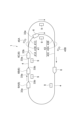
- FIG. 1 is a schematic plan view showing a traveling vehicle system according to an embodiment.
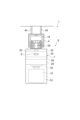
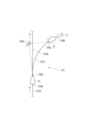
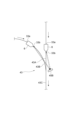
- FIG. 2 is a schematic front view of the overhead traveling vehicle of FIG.
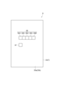
- FIG. 3 is a rear view of the main body of the overhead traveling vehicle of FIG.
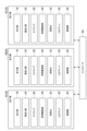
- FIG. 4 is a block diagram showing a functional configuration of the traveling vehicle system of FIG.
- FIG. 5 is an explanatory diagram illustrating a mirror disposed at a branching portion.
- FIG. 6 is an explanatory diagram illustrating a mirror disposed at the junction.
- the traveling vehicle system 1 is a system for transporting an item 10 (see FIG. 2) between placement units 9, 9, using, for example, an overhead traveling vehicle 6 that can move along a track (a predetermined travel path) 4.
- the item 10 includes, for example, containers such as FOUPs (Front Opening Unified Pods) that store multiple semiconductor wafers and reticle pods that store glass substrates, as well as general parts.
- FOUPs Front Opening Unified Pods
- FOUPs Front Opening Unified Pods
- reticle pods that store glass substrates
- an example of a traveling vehicle system 1 in which an overhead traveling vehicle 6 (hereinafter simply referred to as a "traveling vehicle 6") travels along a one-way track 4 installed on the ceiling of a factory or the like will be described.
- the traveling vehicle system 1 includes a track 4, mirrors 45A, 45B, multiple traveling vehicles 6, and multiple placement units 9.
- the track 4 is installed, for example, near the ceiling, which is the space above the worker's head.
- the track 4 is suspended, for example, from the ceiling.
- the track 4 is a predetermined running path for the traveling vehicle 6 to run on.
- the track 4 is supported by supports 40, 40.
- mirrors 45A and 45B are provided along the track 4 and reflect an LED (Light Emitting Diode) array (display) 55 (see FIG. 3) provided on the traveling vehicle 6.
- the track 4 has a branching section 41 including an inflow path 41A that flows in one direction to a predetermined position, a first outflow path 41B that flows out from a predetermined position in one direction, and a second outflow path 41C that flows out from a predetermined position in a direction different from the one direction.
- the mirror 45A is disposed near (to the side of) the branching section 41. As shown in FIG. 5, the mirror 45A reflects an LED array 55 provided on the fall prevention cover 33a of the traveling vehicle 6 of the second outflow path 41C as seen from the traveling vehicle 6 located on the inflow path 41A.
- the track 4 includes a junction 43 including a first inflow passage 43A that flows in along one direction toward a predetermined position, a second inflow passage 43B that flows in from a direction different from the first direction toward the predetermined position, and an outflow passage 43C that flows out from the predetermined position in a direction different from the first direction.
- the mirror 45B is disposed near the junction 43. As shown in FIG.
- the mirror 45B reflects the LED array 55 provided on the fall prevention cover 33b of the traveling vehicle 6 located at the second inflow passage 43B as viewed from the traveling vehicle 6 located at the first inflow passage 43A, and also reflects the LED array 55 provided on the fall prevention cover 33b of the traveling vehicle 6 located at the first inflow passage 43A as viewed from the traveling vehicle 6 located at the second inflow passage 43B.
- the traveling vehicle 6 travels along the track 4 and transports the article 10.
- the traveling vehicle 6 is configured to be able to transfer the article 10.
- the traveling vehicle 6 is an overhead traveling unmanned guided vehicle.
- the number of traveling vehicles 6 provided in the traveling vehicle system 1 is not particularly limited as long as it is three or more.
- the traveling vehicle 6 has a main body unit 7, a running unit 18, an LED array (information output unit) 55, an identification unit 57, an imaging unit (information acquisition unit) 8, and a control unit 50.
- the lateral feed unit 24 collectively transports the ⁇ drive 26, the lifting drive unit 28, and the lifting platform 30 in a direction perpendicular to the running direction of the track 4.
- the ⁇ drive 26 rotates at least one of the lifting drive unit 28 and the lifting platform 30 within a predetermined angle range in a horizontal plane.
- the lifting drive unit 28 raises and lowers the lifting platform 30 by winding or unwinding a suspending material such as a wire, rope, or belt.
- the lifting platform 30 is provided with a chuck that can freely grip or release the article 10.
- a pair of fall prevention covers 33 are provided, for example, at the front and rear of the traveling vehicle 6 in the running direction. The fall prevention cover 33 prevents the article 10 from falling during transport by protruding or retracting a claw (not shown) below the article 10 being transported.
- the placement section 9 is arranged along the track 4 and is provided at a position where the article 10 can be handed over to and from the traveling vehicle 6.
- the placement section 9 includes a buffer and a transfer port.
- the buffer is a placement section where the article 10 is temporarily placed.
- the buffer is a placement section where the article 10 is temporarily placed when the article 10 being transported by the traveling vehicle 6 cannot be transferred to the intended transfer port, for example, because another article 10 is placed at the intended transfer port.
- the transfer port is a placement section for transferring the article 10 to and from a semiconductor processing device (not shown), such as a cleaning device, a film forming device, a lithography device, an etching device, a heat treatment device, or a planarization device.
- the processing device is not particularly limited and may be various devices.
- the placement unit 9 is disposed to the side of the track 4.
- the traveling vehicle 6 transfers the article 10 between the placement unit 9 by using the lateral feed unit 24 to laterally feed the lifting drive unit 28 and the like, and slightly raising and lowering the lifting platform 30.
- the placement unit 9 may also be disposed directly below the track 4. In this case, the traveling vehicle 6 transfers the article 10 between the placement unit 9 by raising and lowering the lifting platform 30.
- the LED array 55 is disposed on the fall prevention cover 33a (33) provided on the rear side of the traveling vehicle 6.
- the LED array 55 may also be disposed on the fall prevention cover 33b (33) provided on the front side of the traveling vehicle 6.
- the LED array 55 is an LED unit in which a plurality of (five) LEDs 55A, 55B are arranged.
- the LED array 55 switches its display mode (outputs both the first information and the second information) based on both the state of the traveling vehicle 6 (the traveling vehicle 6 on which the LED array 55 is provided) and the state of the traveling vehicle (forward traveling vehicle) 6 (hereinafter also referred to as the "forward traveling vehicle 6") located one vehicle ahead of the traveling vehicle in the traveling direction.
- the display mode of the LED array 55 of the traveling vehicle 6 it is possible to identify (understand) both the state of the traveling vehicle 6 on which the LED array 55 is provided and the state of the traveling vehicle 6 located one vehicle ahead of the traveling vehicle 6.
- the LED array 55 changes the display mode according to a combination of lit and unlit LEDs 55A among the four LEDs 55A (hereinafter simply referred to as a "lighting combination").
- the remaining LED 55B is used as parity.
- the LED 55B is used to determine whether or not the combination of lit LEDs 55A is the display mode intended by the control unit 50.
- the display mode of the LED array 55 is switched by the control unit 50.
- the identification unit 57 is disposed near (adjacent to) the LED array 55.
- the identification unit 57 is a predetermined symbol (mark).
- the identification unit 57 may be, for example, a two-dimensional barcode, and may include information such as an identification number that distinguishes each of the multiple traveling vehicles 6.
- the imaging unit 8 captures an image of the LED array 55 provided on the traveling vehicle 6 located in front of the own traveling vehicle 6.
- the imaging unit 8 is disposed on the fall prevention cover 33b (33) provided on the front side of the traveling vehicle 6.
- the imaging unit 8 transmits an image capturing an image of the display state of the LED array 55 to the control unit 50.
- the imaging unit 8 not only captures an image of the LED array 55 provided on the traveling vehicle 6 located in front of the own traveling vehicle 6, but may also capture an image of the LED array 55 reflected via mirrors 45A, 45B arranged along the track 4.
- the control unit 50 is an electronic control unit consisting of a CPU (Central Processing Unit), a ROM (Read Only Memory), a RAM (Random Access Memory), etc.
- the control unit 50 controls various operations in the traveling vehicle 6. Specifically, as shown in FIG. 4, the control unit 50 controls the traveling unit 18, the lateral feed unit 24, the ⁇ drive 26, the lifting drive unit 28, the lifting platform 30, and the LED array 55.
- the control unit 50 can be configured as software in which a program stored in the ROM is loaded onto the RAM and executed by the CPU, for example.
- the control unit 50 may also be configured as hardware such as an electronic circuit.
- the control unit 50 communicates with the controller 60 using a communication line (feeder line) of the track 4, etc.
- the control unit 50 controls the traveling unit 18 to decelerate to a first speed when the distance to the forward traveling vehicle 6 becomes a first predetermined distance, and controls the traveling unit 18 to stop when the distance becomes a second predetermined distance shorter than the first predetermined distance.
- the control unit 50 may also control the traveling unit 18 to accelerate to a predetermined speed when the distance to the forward traveling vehicle 6 is equal to or greater than the first predetermined distance.
- the distance to the forward traveling vehicle 6 can be acquired by an obstacle sensor or the like. In this type of control, the traveling vehicle 6 cannot decelerate until it approaches a predetermined distance from the forward traveling vehicle 6 even if the forward traveling vehicle 6 starts to decelerate, so it cannot start decelerating immediately at the timing when the forward traveling vehicle 6 starts to decelerate.
- the control unit 50 switches the display mode of the LED array 55 according to the traveling state of the vehicle itself and the traveling state of the vehicle ahead 6. Specifically, the control unit 50, for example, receives a command from the controller 60 to acquire the traveling state of the vehicle itself (acceleration state or deceleration state). The control unit 50 also acquires the traveling state of the vehicle ahead 6 (acceleration state or deceleration state) based on the display mode of the LED array 55 of the vehicle ahead 6 captured by the imaging unit 8. The control unit 50 controls the lighting of the LEDs 55A in the LED array 55 so that the display mode corresponds to the combination of the traveling state of the vehicle itself (acceleration state or deceleration state) thus acquired and the traveling state of the vehicle ahead 6 (acceleration state or deceleration state). In other words, the control unit 50 transmits the traveling state of the vehicle itself and the traveling state of the vehicle ahead 6 to the vehicle ahead 6 by switching the display mode of the LED array 55 provided on the vehicle ahead 6.
- the control unit 50 acquires the driving state of the vehicle 6 immediately preceding the vehicle in the driving direction (the vehicle 6 ahead) and the state of the vehicle 6 two vehicles ahead of the vehicle in the driving direction based on the display state captured by the imaging unit 8, the display state captured by the imaging unit 8 via the mirror 45A, or the display state captured by the imaging unit 8 via the mirror 45B.
- the control unit 50 controls the driving unit 18 based on the driving state of the vehicle 6 immediately preceding the vehicle and the driving state of the vehicle 6 two vehicles ahead of the vehicle acquired via the imaging unit 8. Specifically, the control unit 50 acquires the driving state of the vehicle 6 immediately preceding the vehicle and the driving state of the vehicle 6 two vehicles ahead of the vehicle based on the state of the LED array 55 of the vehicle 6 immediately preceding the vehicle captured by the imaging unit 8.
- the control unit 50 for example, extracts a combination of the lighting of the LED array 55 from the acquired captured image, and compares the driving state of the vehicle 6 immediately preceding the vehicle, the driving state of the vehicle 6 two vehicles ahead of the vehicle, and the lighting combination with the combination information stored in association with each other. This allows the control unit 50 to obtain the driving state of the traveling vehicle 6 immediately preceding the own vehicle and the driving state of the traveling vehicle 6 two vehicles prior to the own vehicle.
- the control unit 50 controls the driving unit 18 according to the state of the LED array 55 of the traveling vehicle 6 immediately preceding the host vehicle, acquired via the imaging unit 8. More specifically, the control unit 50 controls the driving unit 18 according to the acquired driving state of the traveling vehicle 6 immediately preceding the host vehicle and the driving state of the traveling vehicle 6 two vehicles prior to the host vehicle. For example, when the control unit 50 acquires that the driving state of the traveling vehicle 6 two vehicles prior to the host vehicle is a decelerating state and the driving state of the traveling vehicle 6 immediately preceding the host vehicle is an accelerating state or a normal driving state, it decelerates the driving unit 18 without following the driving state of the traveling vehicle 6 immediately preceding the host vehicle.
- the normal driving state refers to a state in which the vehicle travels at a constant speed without accelerating or decelerating.
- the control unit 50 determines whether to control the traveling unit 18 based on the positional relationship between the LED array 55 and the identification unit 57 in the captured image acquired by the imaging unit 8. For example, when the identification unit 57 is recognized in a predetermined position (e.g., the lower left of the LED array 55) relative to the LED array 55 in the captured image, the control unit 50 acquires the traveling state of the traveling vehicle 6 immediately preceding the host vehicle and the traveling state of the traveling vehicle 6 immediately preceding the host vehicle from the acquired captured image, and controls the traveling unit 18 according to the traveling state. On the other hand, when the identification unit 57 is not recognized in a predetermined position relative to the LED array 55 in the captured image, the control unit 50 does not control the traveling unit 18 based on the acquired captured image. In other words, the control unit 50 determines that the acquired display mode is not acquired from the LED array 55 provided on the traveling vehicle 6 ahead, and does not control the traveling unit 18.
- a predetermined position e.g., the lower left of the LED array 55
- the control unit 50 also determines whether the display mode is a mirror image reflected on the mirrors 45A and 45B based on the positional relationship between the LED array 55 and the identification unit 57 in the captured image acquired by the imaging unit 8. For example, when the identification unit 57 is recognized in a predetermined position (e.g., the lower left of the LED array 55) relative to the LED array 55 in the captured image, the control unit 50 determines that the captured image (mirror image) is an image of the LED array 55 of the vehicle 6 traveling ahead, not via the mirrors 45A and 45B.
- a predetermined position e.g., the lower left of the LED array 55
- the control unit 50 determines that the captured image (mirror image) is an image acquired via the mirrors 45A and 45B. This allows the control unit 50 to distinguish whether the acquired combination of lights of the LED array 55 is reflected on the mirrors 45A and 45B.
- the controller 60 is an electronic control unit consisting of a CPU (Central Processing Unit), a ROM (Read Only Memory), and a RAM (Random Access Memory).
- the controller 60 can be configured as software, for example, in which a program stored in the ROM is loaded onto the RAM and executed by the CPU.
- the controller 60 may also be configured as hardware, such as an electronic circuit.
- the controller 60 transmits a transport command to cause the traveling vehicle 6 to transport the article 10.
- the traveling vehicle 6C acquires both the traveling state of the first traveling vehicle 6A and the traveling state of the second traveling vehicle 6B based on the display state (information output from the information output unit) of the LED array 55 of the second traveling vehicle 6B, travels based on both the traveling state of the first traveling vehicle 6A and the traveling state of the second traveling vehicle 6B, and further switches the display state of its own LED array 55 based on both the traveling state of its own vehicle and the traveling state of the second traveling vehicle 6B.
- the traveling vehicle 6 located upstream of the branching section 41 recognizes the traveling vehicle 6 located on the first outlet path 41B or the second outlet path 41C, which it is about to proceed through, as the traveling vehicle 6 ahead.
- the traveling vehicle 6 located on the inlet path 41A can capture an image of the LED array 55 of the traveling vehicle 6 located on the first outlet path 41B, and can also capture an image of the LED array 55 of the traveling vehicle 6 located on the second outlet path 41C via the mirror 45A.
- the traveling vehicle 6 located upstream of the merging section 43 i.e., on the first entrance path 43A or the second entrance path 43B, takes into account the order after merging and recognizes the traveling vehicle 6 that will merge first as the traveling vehicle 6 ahead.
- the traveling vehicle 6 located on the first entrance path 43A can capture an image of the LED array 55 of the traveling vehicle 6 located on the second entrance path 43B via the mirror 45B
- the traveling vehicle 6 located on the second entrance path 43B can capture an image of the LED array 55 of the traveling vehicle 6 located on the first entrance path 43A via the mirror 45B.
- the traveling vehicle 6 monitors the distance to an obstacle (including the traveling vehicle) ahead using an obstacle sensor or the like that monitors the front.
- Each traveling vehicle 6 provided in the traveling vehicle system 1 decelerates when the distance to the obstacle (including the traveling vehicle 6) ahead becomes a first predetermined distance, and stops when the distance to the obstacle ahead becomes a second predetermined distance that is shorter than the first predetermined distance.
- the third traveling vehicle 6C can also control the running unit 18 based on the running state of only the traveling vehicle 6 (second traveling vehicle 6B) immediately preceding the third traveling vehicle 6C in the traveling direction.
- the second traveling vehicle 6B may accelerate or decelerate depending on the distance to the first traveling vehicle 6A.
- the third running vehicle 6C of this embodiment which is capable of acquiring the running states of the first running vehicle 6A and the second running vehicle 6B, when it acquires that the running state of the first running vehicle 6A is accelerating and the running state of the second running vehicle 6B is decelerating, it is possible to control the third running vehicle 6C to continue running at a constant speed or to accelerate, rather than following the running state of the second running vehicle 6B. This makes it possible to suppress unnecessary acceleration and deceleration in the third running vehicle 6C, thereby improving the conveying efficiency (processing capacity).
- the second running vehicle 6B may also immediately decelerate.
- the third running vehicle 6C of this embodiment which is capable of acquiring the running states of the first running vehicle 6A and the second running vehicle 6B, when it acquires that the running state of the first running vehicle 6A is in a decelerating state and the running state of the second running vehicle 6B is in an accelerating state, it is possible to control the third running vehicle 6C to continue running at a constant speed or to decelerate, rather than following the running state of the second running vehicle 6B. This suppresses unnecessary acceleration and deceleration in the third running vehicle 6C, and improves the conveying efficiency (processing capacity).
- both the traveling state of the second traveling vehicle 6B (own vehicle) and the traveling state of the first traveling vehicle 6A (front traveling vehicle 6) can be transmitted to the third traveling vehicle 6C (rear traveling vehicle 6).
- the third traveling vehicle 6C which has acquired both the traveling state of the second traveling vehicle 6B and the traveling state of the first traveling vehicle 6A, can control the traveling unit 18 based on the traveling state of the first traveling vehicle 6A, which is two vehicles ahead of the own vehicle, rather than simply following the traveling state of the second traveling vehicle 6B in the traveling direction.
- the traveling unit 18 which has acquired both the traveling state of the second traveling vehicle 6B and the traveling state of the first traveling vehicle 6A
- the expected value of the speed of the second running vehicle 6B can also be known, and if the expected value of the speed of the second running vehicle 6B is known, the expected value of the third running vehicle 6C can also be known.
- the running unit 18 By controlling the running unit 18 according to such an expected value of the third running vehicle 6C, unnecessary acceleration/deceleration in the third running vehicle 6C can be eliminated and a decrease in the speed of the third running vehicle 6C can be avoided, thereby improving the running efficiency (processing capacity) of the entire running vehicle system 1.
- the traveling vehicle 6 and traveling vehicle system 1 of the above embodiment are equipped with an LED array 55 that switches the display mode according to the driving state of the vehicle itself and the traveling vehicle 6 located in front of the vehicle, and an imaging unit 8 that images the LED array 55 provided on the traveling vehicle 6 located in front of the vehicle.
- control unit 50 may control the traveling unit 18 to decelerate to a first speed when the distance to the traveling vehicle 6 located in front of the vehicle becomes a first predetermined distance, and control the traveling unit 18 to stop when the distance becomes a second predetermined distance that is shorter than the first predetermined distance.
- this configuration it is possible to increase the transport capacity while executing control that can prevent the traveling vehicles 6, 6 from colliding with each other.
- the traveling vehicle 6 and traveling vehicle system 1 transmit the traveling state (accelerating or decelerating state) of the vehicle itself and the traveling state (accelerating or decelerating state) of the leading traveling vehicle 6 to the trailing traveling vehicle 6 via the LED array 55.
- the traveling state accelerating or decelerating state
- the traveling state accelerating or decelerating state
- the leading traveling vehicle 6 is in an accelerating or decelerating state
- the traveling state of the traveling vehicle 6 is transmitted to the following traveling vehicle 6 via the LED array 55 as an acceleration state, a normal traveling state, or a deceleration state, but the present invention is not limited to this.
- the traveling state of the traveling vehicle 6 may be transmitted to the following traveling vehicle 6 as an abnormal stop state or a normal stop state.
- the abnormal stop state is a state in which the traveling vehicle 6 has transitioned to an operation for an abnormal stop
- the normal stop state is a state in which the traveling vehicle 6 has transitioned to an operation for a normal stop.
- the braking distance during an abnormal stop is shorter than the braking distance during a normal stop.
- the second traveling vehicle 6B can communicate to the rear traveling vehicle 6 whether its own vehicle has stopped abnormally or normally, and can also communicate to the rear traveling vehicle 6 whether the traveling vehicle 6 located in front of its own vehicle has stopped abnormally or normally.
- the third traveling vehicle 6C can obtain whether the traveling state of the first traveling vehicle 6A and the traveling state of the second traveling vehicle 6B are stopped abnormally or normally.
- the traveling vehicle system 1 of this embodiment can obtain information that the traveling vehicle 6 two vehicles ahead of the vehicle has made an emergency stop, making it possible to respond more quickly than when the driving unit 18 is controlled based on information that the traveling vehicle 6 one vehicle ahead of the vehicle has made an emergency stop. This makes it possible to reduce the possibility of a chain reaction collision.
- the vehicle distance i.e., the first and second predetermined distances in the collision prevention control using the obstacle sensor
- the vehicle distance can be set short, making it possible to improve the transportation efficiency of the traveling vehicles 6 in the traveling vehicle system 1.
- an example of the LED array 55 is described as an example of the information output unit that outputs information to the vehicle 6 traveling behind the vehicle, but the present invention is not limited to this.
- examples of information output include a method using radio wave radio, a method using infrared communication, and a method using feeder radio.
- the method of the above embodiment has an advantage that communication failure is less likely to occur and communication failure caused by temporal changes in the communication environment is less likely to occur compared to the method using radio wave radio.
- the method of the above embodiment has an advantage that it is more resistant to misalignment of the optical axis compared to the method using infrared communication.
- the method of the above embodiment has an advantage that the signal transmission response is faster (latency is shorter) compared to the method using feeder radio.
- a vehicle used in a vehicle system including three or more vehicles that travel in one direction along a predetermined travel route, A main body portion, a traveling unit that causes the main body unit to travel along the traveling path; an information output unit for outputting information to a rear traveling vehicle; an information acquisition unit that acquires the information output from the information output unit provided in a forward traveling vehicle that is located immediately ahead of the vehicle in the traveling direction; A control unit that controls the traveling unit, the information output unit outputs, in addition to first information corresponding to a state of the vehicle, second information corresponding to a state of the vehicle ahead of the vehicle acquired by the information acquisition unit to the vehicle behind; The control unit controls the traveling unit based on both the first information and the second information output from the forward traveling vehicle acquired by the information acquisition unit.
- the information output unit is a display unit that switches a display mode in accordance with the information
- the information acquisition unit is an imaging unit that images the display unit provided in the forward traveling vehicle
- the display unit switches a display mode based on the first information and the second information
- the control unit controls the driving unit of the vehicle itself based on a display state of the display unit of the traveling vehicle in front of the vehicle imaged by the imaging unit.
- the control unit controls the traveling unit to decelerate to a first speed when the distance to the preceding traveling vehicle becomes a first predetermined distance, and controls the traveling unit to stop when the distance becomes a second predetermined distance which is shorter than the first predetermined distance.
- the information output unit switches the information to be output in accordance with a traveling state of the vehicle itself and a traveling state of the forward traveling vehicle;
- the traveling state of the traveling vehicle according to any one of [1] to [3] includes an acceleration state and a deceleration state.
- the information output unit switches the information to be output in accordance with the vehicle's own traveling state and the traveling state of the preceding vehicle,
- the traveling state of the traveling vehicle according to any one of [1] to [4] includes an abnormal stop state and a normal stop state.
- a traveling vehicle system including the traveling vehicle according to any one of [1] to [5], Among the three traveling vehicles included in the traveling vehicle system that are consecutive in the traveling direction, when the traveling vehicle located at the front is a first traveling vehicle, the traveling vehicle located in the middle is a second traveling vehicle, and the traveling vehicle located at the rear is a third traveling vehicle,
- the third running vehicle acquires both the state of the first running vehicle and the state of the second running vehicle based on the information output from the information output unit of the second running vehicle, controls driving based on both the state of the first running vehicle and the state of the second running vehicle, and further outputs both its own state and the state of the second running vehicle from the information output unit of its own running vehicle system.
- 1...Traveling vehicle system 4...Track, 6...Ceiling traveling vehicle (Traveling vehicle, Front traveling vehicle, Rear traveling vehicle), 6A...First traveling vehicle (Traveling vehicle), 6B...Second traveling vehicle (Traveling vehicle), 6C...Third traveling vehicle (Traveling vehicle), 7...Main body, 8...Imaging unit (Information acquisition unit), 10...Item, 18...Traveling unit, 50...Control unit, 55...LED array (Information output unit).
Landscapes
- Engineering & Computer Science (AREA)
- Aviation & Aerospace Engineering (AREA)
- Radar, Positioning & Navigation (AREA)
- Remote Sensing (AREA)
- Physics & Mathematics (AREA)
- General Physics & Mathematics (AREA)
- Automation & Control Theory (AREA)
- Control Of Driving Devices And Active Controlling Of Vehicle (AREA)
Abstract
走行車(6)は、本体部(7)と、走行部(18)と、情報出力部(55)と、情報取得部(8)と、制御部(50)と、を備える。情報出力部(55)は、自機の状態に応じた情報である第一情報に加えて、情報取得部(8)で取得した前方走行車(6)の状態に応じた情報である第二情報も出力する。制御部(50)は、情報取得部(8)によって取得される前方走行車(6)から出力される第一情報及び第二情報の両方に基づいて自機の走行部(18)を制御する。
Description
本発明の一側面は、走行車及び走行車システムに関する。
前方監視用のセンサを備える複数の搬送台車(走行車)が、予め定められた経路を走行する搬送台車システム(走行車システム)が知られている。例えば、特許文献1には、自機の状態に合わせて表示態様を切り替えるLEDアレイと、自機の前方に位置する走行車に設けられているLEDアレイを撮像する撮像部と、撮像部によって撮像された表示態様に基づいて前方の走行車の状態を取得すると共に、取得した状態に基づいて自機の走行部を制御する制御部と、を備える走行車が開示されている。このような走行車では、前方の走行車の状態に応じた動作を迅速に実行することができる。
しかしながら、走行車の走行効率を更に改善するためには、走行方向における一つ前の走行車だけではなく、二つ前の走行車の状態に基づいた走行を行うことが好ましい。
そこで、本発明の一側面の目的は、自機の前方に位置する複数の走行車の状態に応じた動作を迅速に実行するだけでなく、自機の走行効率を改善することができる走行車及び走行車システムを提供することにある。
本発明の一側面に係る走行車は、予め定められた走行経路に沿って一方向に走行する三台以上の走行車を備える走行車システムで用いられる走行車であって、本体部と、本体部を走行経路に沿って走行させる走行部と、後方走行車に情報を出力する情報出力部と、走行方向において自機の一つ前に位置する前方走行車に設けられている情報出力部から出力される情報を取得する情報取得部と、走行部を制御する制御部と、を備え、情報出力部は、自機の状態に応じた第一情報に加えて、情報取得部で取得した自機の前方走行車の状態に応じた第二情報も後方走行車に出力し、制御部は、情報取得部によって取得される前方走行車から出力される第一情報及び第二情報の両方に基づいて走行部を制御する。
この構成の走行車は、自機の状態及び前方走行車の状態との両方を後方走行車に伝達することができる。これにより、後方走行車は、走行方向において自機の一つ前の走行車の状態(第一情報)及び自機の二つ前の走行車の状態(第二情報)を取得でき、それらに基づいた走行部の制御が可能になる。この結果、直接検知できない二台前方に位置する走行車の状態に応じた動作も迅速に実行できるため、自機の走行効率を改善することができる。
本発明の一側面に係る走行車では、情報出力部は、情報に合わせて表示態様を切り替える表示部であり、情報取得部は、前方走行車に設けられている表示部を撮像する撮像部であり、表示部は、第一情報及び第二情報に基づいて表示態様を切り替え、制御部は、撮像部によって撮像される前方走行車の表示部の表示態様に基づいて、自機の走行部を制御してもよい。この構成では、安定的な情報伝達が可能となり、かつレスポンスを高めることができる。
本発明の一側面に係る走行車では、制御部は、前方走行車までの距離が第一所定距離になると第一速度にまで減速するように走行部を制御し、第一所定距離よりも短い第二所定距離になると停止するように走行部を制御してもよい。この構成では、走行車同士が衝突することを防止できる。
本発明の一側面に係る走行車では、情報出力部は、自機の走行状態及び前方走行車の走行状態に合わせて出力する情報を切り換え、走行状態には、加速状態と減速状態とが含まれてもよい。この構成では、自機が加速状態であるか減速状態であるかを後方走行車に伝達することが可能になると共に、自機の前方走行車が加速状態であるか減速状態であるかを後方走行車に伝達することが可能になる。
本発明の一側面に係る走行車では、情報出力部は、自己の走行状態及び前方走行車の走行状態に合わせて出力する情報を切り換え、走行状態には、異常停止状態と通常停止状態とが含まれてもよい。なお、ここでいう異常停止状態とは、異常停止をする動作に移行した状態をいい、必ずしも停止した状態でなくてもよい。同様に、ここでいう通常停止状態とは、通常停止をする動作に移行した状態をいい、必ずしも停止した状態でなくてもよい。異常停止と通常停止との違いは、それぞれの動作に移行してから自機が完全に停止するまでの距離(制動距離)であり、異常停止の場合は、通常停止の場合よりも短い。この構成では、自機が異常停止であるか通常停止であるかを後方走行車に伝達することが可能になると共に、自機の前方走行車が異常停止であるか通常停止であるかを後方走行車に伝達することが可能になる。
本発明の一側面に係る走行車システムでは、上記の走行車を備える走行車システムであって、走行車システムに含まれる走行車の中で走行方向に連続する三台の走行車のうち、先頭に位置する走行車を第一走行車、中間に位置する走行車を第二走行車、最後尾に位置する走行車を第三走行車としたとき、第三走行車は、第二走行車の情報出力部から出力される情報に基づいて、第一走行車の状態と第二走行車の状態との両方を取得すると共に、第一走行車の状態と第二走行車の状態との両方に基づいて走行制御し、更に、自機の状態と第二走行車の状態との両方を自機の情報出力部から出力してもよい。この構成では、第一走行車の状態及び第二走行車の状態との両方を後方の第三走行車に伝達することができる。これにより、第一走行車の状態及び第二走行車の状態との両方を取得した後方の第三走行車は、単に、走行方向において自機の一つ前の第二走行車に追随するだけでなく、二つ前の第一走行車の状態に基づいた走行部の制御が可能になる。この結果、第三走行車の前方に位置する走行車の状態に応じた動作を迅速に実行するだけでなく、走行車システムとして走行する走行車の走行効率を改善することができる。
本発明の一側面によれば、自機の前方に位置する複数の走行車の状態に応じた動作を迅速に実行するだけでなく、自機の走行効率を改善することができる。
以下、図面を参照して一実施形態に係る天井走行車(走行車)6及び走行車システム1について説明する。図面の説明において、同一要素には同一符号を付し、重複する説明を省略する。
走行車システム1は、例えば、軌道(予め定められた走行経路)4に沿って移動可能な天井走行車6を用いて、物品10(図2参照)を載置部9,9間で搬送するためのシステムである。物品10には、例えば、複数の半導体ウェハを格納するFOUP(Front Opening Unified Pod)及びガラス基板を格納するレチクルポッド等のような容器、並びに一般部品等が含まれる。ここでは、例えば、工場等において、天井走行車6(以下、単に「走行車6」と称する。)が、工場の天井等に敷設された一方通行の軌道4に沿って走行する走行車システム1を例に挙げて説明する。図1に示されるように、走行車システム1は、軌道4、ミラー45A,45B、複数の走行車6及び複数の載置部9を備える。
図2に示されるように、軌道4は、例えば、作業者の頭上スペースである天井付近に敷設されている。軌道4は、例えば天井から吊り下げられている。軌道4は、走行車6を走行させるための予め定められた走行路である。軌道4は、支柱40,40により支持される。
図1に示されるように、ミラー45A,45B(例えば、広角ミラー)は、軌道4沿いに設けられると共に、走行車6に設けられるLED(Light Emitting Diode)アレイ(表示部)55(図3参照)を映し出す。軌道4は、所定位置に一方向に沿って流入する流入路41Aと、所定位置から一方向に沿って流出する第一流出路41Bと、所定位置から一方向とは異なる方向に流出する第二流出路41Cとを含んで構成される分岐部41を備える。ミラー45Aは、分岐部41の近傍(側方)に配置されている。図5に示されるように、ミラー45Aは、流入路41Aに位置する走行車6から見て第二流出路41Cの走行車6の落下防止カバー33aに設けられるLEDアレイ55を映し出す。
また、図1に示されるように、軌道4は、所定位置に向かって一方向に沿って流入する第一流入路43Aと、所定位置に向かって一方向とは異なる方向から流入する第二流入路43Bと、所定位置から一方向とは異なる方向に流出する流出路43Cとを含んで構成される合流部43を備える。ミラー45Bは、合流部43の近傍に配置されている。図6に示されるように、ミラー45Bは、第一流入路43Aに位置する走行車6から見て第二流入路43Bに位置する走行車6の落下防止カバー33bに設けられるLEDアレイ55を映し出すと共に、第二流入路43Bに位置する走行車6から見て第一流入路43Aに位置する走行車6の落下防止カバー33bに設けられるLEDアレイ55を映し出す。
図2に示されるように、走行車6は、軌道4に沿って走行し、物品10を搬送する。走行車6は、物品10を移載可能に構成されている。走行車6は、天井走行式無人搬送車である。走行車システム1が備える走行車6の台数は、三台以上であれば、特に限定されない。図2及び図3に示されるように、走行車6は、本体部7と、走行部18と、LEDアレイ(情報出力部)55と、識別部57と、撮像部(情報取得部)8と、制御部50と、を有する。
横送り部24は、θドライブ26、昇降駆動部28及び昇降台30を一括して、軌道4の走行方向と直角な方向に横送りする。θドライブ26は、昇降駆動部28及び昇降台30の少なくとも何れかを水平面内で所定の角度範囲内で回動させる。昇降駆動部28は、昇降台30をワイヤ、ロープ及びベルト等の吊持材の巻取りないし繰出しによって昇降させる。昇降台30には、チャックが設けられており、物品10の把持又は解放が自在とされている。落下防止カバー33は、例えば走行車6の走行方向の前後に一対設けられている。落下防止カバー33は、搬送する物品10の下方に図示しない爪等を出没させて、搬送中に物品10が落下することを防止する。
図1及び図2に示されるように、載置部9は、軌道4に沿って配置され、走行車6との間で物品10の受け渡し可能な位置に設けられている。載置部9には、バッファ及び受渡ポートが含まれる。バッファは、物品10が一時的に載置される載置部である。バッファは、例えば、目的とする受渡ポートに他の物品10が載置されている等の理由により、走行車6が搬送している物品10をその受渡ポートに移載できない場合に、物品10が仮置きされる載置部である。受渡ポートは、例えば洗浄装置、成膜装置、リソグラフィ装置、エッチング装置、熱処理装置、平坦化装置をはじめとする半導体の処理装置(図示せず)に対して物品10の受渡を行うための載置部である。なお、処理装置は、特に限定されず、種々の装置であってもよい。
例えば、載置部9は、軌道4の側方に配置されている。この場合、走行車6は、横送り部24で昇降駆動部28等を横送りし、昇降台30を僅かに昇降させることにより、載置部9との間で物品10を受け渡しする。なお、図示はしないが載置部9は、軌道4の直下に配置されてもよい。この場合、走行車6は、昇降台30を昇降させることにより、載置部9との間で物品10を受け渡しする。
LEDアレイ55は、図3に示されるように、走行車6の後側に設けられる落下防止カバー33a(33)に配置されている。なお、LEDアレイ55は、走行車6の前側に設けられる落下防止カバー33b(33)にも配置されてもよい。LEDアレイ55は、複数(五つ)のLED55A,55Bが配列されたLEDユニットである。LEDアレイ55は、自機の走行車6(LEDアレイ55が設けられた走行車6)の状態と、走行方向において自機の一つ前に位置する走行車(前方走行車)6(以下、「前方走行車6」とも称する。)の状態との両方に基づいて表示態様が切り替わる(第一情報及び第二情報の両方を出力する)。言い替えれば、走行車6のLEDアレイ55の表示態様を見れば、そのLEDアレイ55が設けられている走行車6の状態と、更にその走行車6の一つ前に位置する走行車6の状態との両方を識別(把握)することができる。
LEDアレイ55は、四つのLED55Aにおいて点灯するLED55Aと点灯しないLED55Aとの組み合わせ(以後、単に「点灯の組み合わせ」と称する。)によって表示態様を変化させる。残りの一つのLED55Bは、パリティとして用いられる。すなわち、LED55Bは、四つのLED55Aの点灯の組み合わせが、制御部50によって意図された表示態様であるか否かを判定するために用いられる。LEDアレイ55における表示態様の切り替えは、制御部50によって行われる。
識別部57は、LEDアレイ55の近傍(隣り合うように)に配置される。識別部57は予め定められた記号(マーク)である。識別部57は、例えば、二次元バーコード等であってもよく、複数の走行車6をそれぞれ区別する識別番号等の情報を含んでいてもよい。
撮像部8は、自機の走行車6の前方に位置する走行車6に設けられているLEDアレイ55を撮像する。撮像部8は、走行車6の前側に設けられる落下防止カバー33b(33)に配置されている。撮像部8は、LEDアレイ55の表示態様を撮像した撮像画像を制御部50に送信する。なお、後段でも説明するが、撮像部8は、自己の走行車6の前方に位置する走行車6に設けられているLEDアレイ55を撮像するだけでなく、軌道4に沿って配置されるミラー45A,45Bを介して映し出されるLEDアレイ55も撮像する場合がある。
制御部50は、CPU(Central Processing Unit)、ROM(Read Only Memory)及びRAM(Random Access Memory)等からなる電子制御ユニットである。制御部50は、走行車6における各種動作を制御する。具体的には、図4に示されるように、制御部50は、走行部18と、横送り部24と、θドライブ26と、昇降駆動部28と、昇降台30と、LEDアレイ55と、を制御する。制御部50は、例えばROMに格納されているプログラムがRAM上にロードされてCPUで実行されるソフトウェアとして構成することができる。制御部50は、電子回路等によるハードウェアとして構成されてもよい。制御部50は、軌道4の通信線(フィーダー線)等を利用して、コントローラ60と通信を行う。
制御部50は、前方走行車6までの距離が第一所定距離になると第一速度にまで減速するように走行部18を制御し、第一所定距離よりも短い第二所定距離になると停止するように走行部18を制御する。また、制御部50は、前方走行車6までの距離が第一所定距離以上あると、所定速度まで加速するように制御する場合もある。前方走行車6までの距離は、障害物センサ等で取得することができる。このような制御では、走行車6は、例えば、前方走行車6が減速を開始しても、前方走行車6に対して所定距離に近づくまで減速できないので、前方走行車6が減速を開始したタイミングですぐに減速を開始することができない。このため、走行車6は、前方走行車6との衝突を避けるため、車間距離を長めに確保した状態で走行する必要性が生じ、ひいては搬送能力の低下につながるという問題があった。そこで、本実施形態では、上記の制御に加え、下記に示す制御が行われている。
制御部50は、自機の走行状態と前方走行車6の走行状態とに合わせてLEDアレイ55の表示態様を切り替える。具体的には、制御部50は、例えば、コントローラ60から指令を受け取って自機の走行状態(加速状態又は減速状態)を取得する。また、制御部50は、撮像部8によって撮像された前方走行車6のLEDアレイ55の表示態様に基づいて、前方走行車6の走行状態(加速状態又は減速状態)を取得する。制御部50は、このように取得した自機の走行状態(加速状態又は減速状態)と、前方走行車6の走行状態(加速状態又は減速状態)との組み合わせに対応する表示態様となるように、LEDアレイ55におけるLED55Aの点灯を制御する。すなわち、制御部50は、走行車6に設けられているLEDアレイ55の表示態様を切り替えることによって、自機の走行状態と前方走行車6の走行状態とを後方走行車6に伝達する。
制御部50は、撮像部8によって撮像された表示態様、ミラー45Aを介して撮像部8によって撮像された表示態様又はミラー45Bを介して撮像部8によって撮像された表示態様に基づいて走行方向において自機の一つ前の走行車6(前方走行車6)の走行状態と、走行方向において自機の二つ前の走行車6の状態と、を取得する。制御部50は、撮像部8を介して取得した自機の一つ前の走行車6の走行状態及び自機の二つ前の走行車6の走行状態に基づいて走行部18を制御する。具体的には、制御部50は、撮像部8によって撮像された自機の一つ前の走行車6のLEDアレイ55の態様に基づいて、自機の一つ前の走行車6の走行状態と自機の二つ前の走行車6の走行状態とを取得する。制御部50は、例えば、取得した撮像画像からLEDアレイ55の点灯の組み合わせを抽出し、自機の一つ前の走行車6の走行状態と、自機の二つ前の走行車6の走行状態と、点灯の組み合わせと、を関連付けて記憶させた組み合わせ情報に照合をかける。これにより、制御部50は、自機の一つ前の走行車6の走行状態と、自機の二つ前の走行車6の走行状態と、を取得する。
制御部50は、撮像部8を介して取得した自機の一つ前の走行車6のLEDアレイ55の態様に応じて、走行部18を制御する。より詳細には、制御部50は、取得した自機の一つ前の走行車6の走行状態と自機の二つ前の走行車6の走行状態とに応じて、走行部18を制御する。例えば、制御部50は、自機の二つ前の走行車6の走行状態が減速状態であり、自機の一つ前の走行車6の走行状態が加速状態又は通常走行状態であることを取得すると、走行部18を自機の一つ前の走行車6の走行状態に追随させることなく減速させる。なお、通常走行状態とは、加減速なく一定の速度で走行する状態をいう。
制御部50は、撮像部8によって取得される撮像画像におけるLEDアレイ55と識別部57との位置関係に基づいて、走行部18を制御するかしないかを決定する。例えば、制御部50は、撮像画像においてLEDアレイ55に対して所定の位置(例えば、LEDアレイ55の左下)に識別部57が認識される場合には、取得した撮像画像から自機の一つ前の走行車6の走行状態と自機の二つ前の走行車6の走行状態とを取得し、当該走行状態に応じて走行部18を制御する。一方、制御部50は、撮像画像においてLEDアレイ55に対して所定の位置に識別部57が認識されない場合には、取得した撮像画像に基づいて走行部18を制御しない。すなわち、制御部50は、取得した表示態様は前方走行車6に設けられたLEDアレイ55から取得したものではないと判定し、走行部18を制御しない。
また、制御部50は、撮像部8によって取得される撮像画像におけるLEDアレイ55と識別部57との位置関係に基づいて、表示態様がミラー45A,45Bに映し出された鏡像であるか否かを判定する。例えば、制御部50は、撮像画像においてLEDアレイ55に対して所定の位置(例えば、LEDアレイ55の左下)に識別部57が認識される場合には、ミラー45A,45Bを介さず、前方走行車6のLEDアレイ55が撮像された撮像画像(鏡像)であると判定する。一方、制御部50は、撮像画像においてLEDアレイ55に対して所定の位置に識別部57が認識されない場合には、ミラー45A,45Bを介して取得された撮像画像(鏡像)であると判定する。これにより、制御部50は、取得されたLEDアレイ55の点灯の組み合わせが、ミラー45A,45Bに映し出されたものか否かを区別することができる。
コントローラ60は、CPU(Central Processing Unit)、ROM(Read Only Memory)及びRAM(Random Access Memory)等からなる電子制御ユニットである。コントローラ60は、例えばROMに格納されているプログラムがRAM上にロードされてCPUで実行されるソフトウェアとして構成することができる。コントローラ60は、電子回路等によるハードウェアとして構成されてもよい。コントローラ60は、走行車6に物品10を搬送させる搬送指令を送信する。
このような構成の走行車システム1では、図1に示されるように、走行車システム1に含まれる走行車6の中で走行方向に連続する三台の走行車のうち、先頭(最下流)に位置する走行車を第一走行車6A、中間に位置する走行車6を第二走行車6B、最後尾(最上流)に位置する走行車6(自機)を第三走行車6Cとしたとき、第三走行車6Cは、第二走行車6BのLEDアレイ55の表示態様(情報出力部から出力される情報)に基づいて、第一走行車6Aの走行状態と第二走行車6Bの走行状態との両方を取得すると共に、第一走行車6Aの走行状態と第二走行車6Bの走行状態との両方に基づいて走行し、更に、自機の走行状態と第二走行車6Bの走行状態との両方に基づいて自機のLEDアレイ55の表示態様を切り替える。
また、本実施形態の走行車システム1では、分岐部41を挟んで走行車6が連続する場合、分岐部41の上流側(すなわち流入路41A)に位置する走行車6は、これから進行しようとする第一流出路41B又は第二流出路41Cに位置する走行車6を前方走行車6として認識をする。上述したように、流入路41Aに位置する走行車6は、第一流出路41Bに位置する走行車6のLEDアレイ55を撮像することが可能であり、第二流出路41Cに位置する走行車6のLEDアレイ55もミラー45Aを介して撮像することが可能である。
また、本実施形態の走行車システム1では、合流部43を挟んで走行車6が連続する場合、合流部43の上流側、すなわち第一流入路43A又は第二流入路43Bに位置する走行車6は、合流後の順番を考慮して、先に合流する走行車6を前方走行車6として認識をする。上述したように、第一流入路43Aに位置する走行車6は、第二流入路43Bに位置する走行車6のLEDアレイ55をミラー45Bを介して撮像することが可能であり、第二流入路43Bに位置する走行車6は、第一流入路43Aに位置する走行車6のLEDアレイ55をミラー45Bを介して撮像することが可能である。
本実施形態の走行車システム1の特徴的な動作について説明する。走行車6は、前方を監視する障害物センサ等によって前方の障害物(走行車も含まれる)までの距離を監視している。走行車システム1に備わる走行車6のそれぞれは、前方の障害物(走行車6を含む)までの距離が第一所定距離となった場合に減速し、前方の障害物までの距離が第一所定距離よりも短い第二所定距離となった場合に停止する。上述した構成の走行車システム1においては、第三走行車6Cは、走行方向において自機の一つ前の走行車6(第二走行車6B)のみの走行状態に基づいて走行部18を制御することもできる。第二走行車6Bは、第一走行車6Aとの距離によっては加速する場合もあれば、減速する場合もある。
ここで、第二走行車6Bが減速した場合であっても、第一走行車6Aが加速状態となっている場合には、第二走行車6Bもすぐに加速状態になることがある。このような状況を考慮して、第一走行車6Aの走行状態及び第二走行車6Bの走行状態を取得することができる本実施形態の第三走行車6Cでは、第一走行車6Aの走行状態が加速状態であり、第二走行車6Bの走行状態が減速状態であることを取得すると、第二走行車6Bの走行状態に追随させるのではなく、一定の速度で走行を続けさせたり、加速させたりするといった制御が可能となる。これにより、第三走行車6Cにおける不要な加減速を抑制することができるので、搬送効率(処理能力)を向上させることができる。
また、第二走行車6Bが加速した場合であっても、第一走行車6Aが減速状態となっている場合には、第二走行車6Bもすぐに減速状態になることがある。このような状況を考慮して、第一走行車6Aの走行状態及び第二走行車6Bの走行状態を取得することができる本実施形態の第三走行車6Cでは、第一走行車6Aの走行状態が減速状態であり、第二走行車6Bの走行状態が加速状態であることを取得すると、第二走行車6Bの走行状態に追随させるのではなく、一定の速度で走行を続けさせたり、減速させたりするといった制御が可能となる。これにより、第三走行車6Cにおける不要な加減速が抑制され、搬送効率(処理能力)を向上させることができる。
上記実施形態の走行車6及び走行車システム1における作用効果について説明する。上記実施形態の走行車システム1及び走行車6では、第二走行車6B(自機)の走行状態及び第一走行車6A(前方走行車6)の走行状態との両方を第三走行車6C(後方走行車6)に伝達することができる。これにより、第二走行車6Bの走行状態及び第一走行車6Aの走行状態との両方を取得した第三走行車6Cは、単に、走行方向において自機の一つ前の第二走行車6Bの走行状態に追随するだけでなく、二つ前の第一走行車6Aの走行状態に基づいた走行部18の制御が可能になる。この結果、自機の前方に位置する複数の走行車6の走行状態に応じた動作を迅速に実行するだけでなく、自機の走行効率を改善することができる。
より詳細には、第一走行車6Aの加減速の状態が分かれば、第二走行車6Bの速度の期待値も分かり、第二走行車6Bの速度の期待値が分かれば、第三走行車6Cの期待値も分かる。このような第三走行車6Cの期待値に合わせて走行部18を制御すれば、第三走行車6Cにおける不要な加減速を無くすことができ、第三走行車6Cの速度低下が避けられるので、走行車システム1全体の走行効率(処理能力)を高めることができる。
上記実施形態の走行車6及び走行車システム1は、自機及び自機の前方に位置する走行車6の走行状態に合わせて表示態様を切り替えるLEDアレイ55と、自機の前方に位置する走行車6に設けられているLEDアレイ55を撮像する撮像部8と、を備える。この構成では、通信環境の時間的な変化に起因する通信不良がおき難く、安定的な情報伝達が可能となり、かつレスポンスを高めることができる。
上記実施形態の走行車6及び走行車システム1は、制御部50は、自機の前方に位置する走行車6までの距離が第一所定距離になると第一速度にまで減速するように走行部18を制御し、第一所定距離よりも短い第二所定距離になると停止するように走行部18を制御してもよい。この構成では、走行車6,6同士が衝突することを防止できる制御を実行しつつ、搬送能力を高めることができる。
上記実施形態の走行車6及び走行車システム1は、後方走行車6に対してLEDアレイ55を介して、自機の走行状態(加速状態又は減速状態)及び前方走行車6の走行状態(加速状態又は減速状態)が伝達されている。この構成では、自機が加速状態であるか減速状態であるかを後方走行車6に伝達することが可能になると共に、前方走行車6が加速状態であるか減速状態であるかを後方走行車6に伝達することが可能になる。
以上、一実施形態について説明したが、本発明の一側面は、上記実施形態に限られない。発明の趣旨を逸脱しない範囲で種々の変更が可能である。
(変形例1)
上記実施形態では、走行車6の走行状態として、加速状態、通常走行状態又は減速状態であることをLEDアレイ55を介して後方走行車6に伝達することを例に挙げて説明したが、これに限定されない。例えば、走行車6の走行状態として、通常走行状態又は減速状態であることに代えて又は加えて、異常停止状態であるか又は通常停止状態であるかを後方走行車6に伝達してもよい。上述したように、異常停止状態とは、異常停止をする動作に移行した状態であり、通常停止状態とは、通常停止をする動作に移行した状態である。また、異常停止時の制動距離は、通常停止時の制動距離よりも短い。
上記実施形態では、走行車6の走行状態として、加速状態、通常走行状態又は減速状態であることをLEDアレイ55を介して後方走行車6に伝達することを例に挙げて説明したが、これに限定されない。例えば、走行車6の走行状態として、通常走行状態又は減速状態であることに代えて又は加えて、異常停止状態であるか又は通常停止状態であるかを後方走行車6に伝達してもよい。上述したように、異常停止状態とは、異常停止をする動作に移行した状態であり、通常停止状態とは、通常停止をする動作に移行した状態である。また、異常停止時の制動距離は、通常停止時の制動距離よりも短い。
この構成では、第二走行車6Bは、自機が異常停止であるか通常停止であるかを後方走行車6に伝達することが可能になると共に、自機の前方に位置する走行車6が異常停止であるか通常停止であるかを後方走行車6に伝達することが可能になる。言い替えれば、第三走行車6Cは、第一走行車6Aの走行状態及び第二走行車6Bの走行状態が異常停止であるか通常停止であるかを取得できる。
前方走行車6が緊急停止をしたときに、後方走行車6は、停止が間に合わずに前方走行車6に衝突する可能性がある。そして、三台以上の走行車6が連続して走行している場合には、更に後続の走行車6が次々と衝突する可能性もある。この点、本実施形態の走行車システム1では、自機の二つ前の走行車6が緊急停止をしたという情報を取得することができるので、自機の一つ前の走行車6が緊急停止をしたという情報に基づいて走行部18が制御される場合と比べて迅速な対応が可能となる。これにより、玉突き的な衝突の可能性を抑制することができる。また、この構成では、車間距離(すなわち、障害物センサを利用した衝突防止制御における第一所定距離及び第二所定距離)を短く設定することができるので、走行車システム1における走行車6の搬送効率を高めることができる。
(変形例2)
上記実施形態又は変形例では、自機の後方走行車6に対して情報を出力する情報出力部の一例として、LEDアレイ55を採用する例を挙げて説明したが、これに限定されない。例えば、情報を出力する例として、電波無線を使用する方法、赤外線通信を使用する方法、フィーダ無線を使用する方法が考えられる。しかしながら、上記実施形態の方法は、電波無線を使用する方法と比べて、通信不良がおきにくく、また、通信環境の時間的な変化に起因する通信不良がおきにくいというメリットがある。また、上記実施形態の方法は、赤外線通信を使用する方法と比べて、光軸のずれに対して強いというメリットがある。また、上記実施形態の方法は、フィーダ無線を使用する方法と比べて、信号伝達レスポンスが早い(レイテンシが短い)というメリットがある。
上記実施形態又は変形例では、自機の後方走行車6に対して情報を出力する情報出力部の一例として、LEDアレイ55を採用する例を挙げて説明したが、これに限定されない。例えば、情報を出力する例として、電波無線を使用する方法、赤外線通信を使用する方法、フィーダ無線を使用する方法が考えられる。しかしながら、上記実施形態の方法は、電波無線を使用する方法と比べて、通信不良がおきにくく、また、通信環境の時間的な変化に起因する通信不良がおきにくいというメリットがある。また、上記実施形態の方法は、赤外線通信を使用する方法と比べて、光軸のずれに対して強いというメリットがある。また、上記実施形態の方法は、フィーダ無線を使用する方法と比べて、信号伝達レスポンスが早い(レイテンシが短い)というメリットがある。
上記実施形態及び変形例では、自機を基準として、二つ前の走行車6の走行状態を取得する例を挙げて説明したが、同様の技術的思想によって三つ前の走行車6の走行状態までを取得する等、適宜の変更が可能である。
本発明の一側面の技術主題は以下のとおりに記載され得る。
[1]
予め定められた走行経路に沿って一方向に走行する三台以上の走行車を備える走行車システムで用いられる走行車であって、
本体部と、
前記本体部を前記走行経路に沿って走行させる走行部と、
後方走行車に情報を出力する情報出力部と、
走行方向において自機の一つ前に位置する前方走行車に設けられている前記情報出力部から出力される前記情報を取得する情報取得部と、
前記走行部を制御する制御部と、を備え、
前記情報出力部は、自機の状態に応じた第一情報に加えて、前記情報取得部で取得した自機の前記前方走行車の状態に応じた第二情報も前記後方走行車に出力し、
前記制御部は、前記情報取得部によって取得される前記前方走行車から出力される前記第一情報及び前記第二情報の両方に基づいて前記走行部を制御する、走行車。
[2]
前記情報出力部は、前記情報に合わせて表示態様を切り替える表示部であり、
前記情報取得部は、前記前方走行車に設けられている前記表示部を撮像する撮像部であり、
前記表示部は、前記第一情報及び前記第二情報に基づいて表示態様を切り替え、
前記制御部は、前記撮像部によって撮像される前記前方走行車の前記表示部の表示態様に基づいて、自機の前記走行部を制御する、[1]記載の走行車。
[3]
制御部は、前記前方走行車までの距離が第一所定距離になると第一速度にまで減速するように前記走行部を制御し、前記第一所定距離よりも短い第二所定距離になると停止するように前記走行部を制御する、[1]又は[2]記載の走行車。
[4]
前記情報出力部は、自機の走行状態及び前記前方走行車の走行状態に合わせて出力する前記情報を切り換え、
前記走行状態には、加速状態と減速状態とが含まれる、[1]~[3]の何れか一つに記載の走行車。
[5]
前記情報出力部は、自己の走行状態及び前記前方走行車の走行状態に合わせて出力する前記情報を切り換え、
前記走行状態には、異常停止状態と通常停止状態とが含まれる、[1]~[4]の何れか一つに記載の走行車。
[6]
[1]~[5]の何れか一つに記載の走行車を備える走行車システムであって、
前記走行車システムに含まれる走行車の中で前記走行方向に連続する三台の走行車のうち、先頭に位置する走行車を第一走行車、中間に位置する走行車を第二走行車、最後尾に位置する走行車を第三走行車としたとき、
前記第三走行車は、前記第二走行車の前記情報出力部から出力される前記情報に基づいて、前記第一走行車の状態と前記第二走行車の状態との両方を取得すると共に、前記第一走行車の状態と前記第二走行車の状態との両方に基づいて走行制御し、更に、自機の状態と前記第二走行車の状態との両方を自機の前記情報出力部から出力する、走行車システム。
[1]
予め定められた走行経路に沿って一方向に走行する三台以上の走行車を備える走行車システムで用いられる走行車であって、
本体部と、
前記本体部を前記走行経路に沿って走行させる走行部と、
後方走行車に情報を出力する情報出力部と、
走行方向において自機の一つ前に位置する前方走行車に設けられている前記情報出力部から出力される前記情報を取得する情報取得部と、
前記走行部を制御する制御部と、を備え、
前記情報出力部は、自機の状態に応じた第一情報に加えて、前記情報取得部で取得した自機の前記前方走行車の状態に応じた第二情報も前記後方走行車に出力し、
前記制御部は、前記情報取得部によって取得される前記前方走行車から出力される前記第一情報及び前記第二情報の両方に基づいて前記走行部を制御する、走行車。
[2]
前記情報出力部は、前記情報に合わせて表示態様を切り替える表示部であり、
前記情報取得部は、前記前方走行車に設けられている前記表示部を撮像する撮像部であり、
前記表示部は、前記第一情報及び前記第二情報に基づいて表示態様を切り替え、
前記制御部は、前記撮像部によって撮像される前記前方走行車の前記表示部の表示態様に基づいて、自機の前記走行部を制御する、[1]記載の走行車。
[3]
制御部は、前記前方走行車までの距離が第一所定距離になると第一速度にまで減速するように前記走行部を制御し、前記第一所定距離よりも短い第二所定距離になると停止するように前記走行部を制御する、[1]又は[2]記載の走行車。
[4]
前記情報出力部は、自機の走行状態及び前記前方走行車の走行状態に合わせて出力する前記情報を切り換え、
前記走行状態には、加速状態と減速状態とが含まれる、[1]~[3]の何れか一つに記載の走行車。
[5]
前記情報出力部は、自己の走行状態及び前記前方走行車の走行状態に合わせて出力する前記情報を切り換え、
前記走行状態には、異常停止状態と通常停止状態とが含まれる、[1]~[4]の何れか一つに記載の走行車。
[6]
[1]~[5]の何れか一つに記載の走行車を備える走行車システムであって、
前記走行車システムに含まれる走行車の中で前記走行方向に連続する三台の走行車のうち、先頭に位置する走行車を第一走行車、中間に位置する走行車を第二走行車、最後尾に位置する走行車を第三走行車としたとき、
前記第三走行車は、前記第二走行車の前記情報出力部から出力される前記情報に基づいて、前記第一走行車の状態と前記第二走行車の状態との両方を取得すると共に、前記第一走行車の状態と前記第二走行車の状態との両方に基づいて走行制御し、更に、自機の状態と前記第二走行車の状態との両方を自機の前記情報出力部から出力する、走行車システム。
1…走行車システム、4…軌道、6…天井走行車(走行車、前方走行車、後方走行車)、6A…第一走行車(走行車)、6B…第二走行車(走行車)、6C…第三走行車(走行車)、7…本体部、8…撮像部(情報取得部)、10…物品、18…走行部、50…制御部、55…LEDアレイ(情報出力部)。
Claims (6)
- 予め定められた走行経路に沿って一方向に走行する三台以上の走行車を備える走行車システムで用いられる走行車であって、
本体部と、
前記本体部を前記走行経路に沿って走行させる走行部と、
後方走行車に情報を出力する情報出力部と、
走行方向において自機の一つ前に位置する前方走行車に設けられている前記情報出力部から出力される前記情報を取得する情報取得部と、
前記走行部を制御する制御部と、を備え、
前記情報出力部は、自機の状態に応じた第一情報に加えて、前記情報取得部で取得した自機の前記前方走行車の状態に応じた第二情報も前記後方走行車に出力し、
前記制御部は、前記情報取得部によって取得される前記前方走行車から出力される前記第一情報及び前記第二情報の両方に基づいて前記走行部を制御する、走行車。 - 前記情報出力部は、前記情報に合わせて表示態様を切り替える表示部であり、
前記情報取得部は、前記前方走行車に設けられている前記表示部を撮像する撮像部であり、
前記表示部は、前記第一情報及び前記第二情報に基づいて表示態様を切り替え、
前記制御部は、前記撮像部によって撮像される前記前方走行車の前記表示部の表示態様に基づいて、自機の前記走行部を制御する、請求項1記載の走行車。 - 前記制御部は、前記前方走行車までの距離が第一所定距離になると第一速度にまで減速するように前記走行部を制御し、前記第一所定距離よりも短い第二所定距離になると停止するように前記走行部を制御する、請求項1又は2記載の走行車。
- 前記情報出力部は、自機の走行状態及び前記前方走行車の走行状態に合わせて出力する前記情報を切り換え、
前記走行状態には、加速状態と減速状態とが含まれる、請求項1又は2記載の走行車。 - 前記情報出力部は、自己の走行状態及び前記前方走行車の走行状態に合わせて出力する前記情報を切り換え、
前記走行状態には、異常停止状態と通常停止状態とが含まれる、請求項1又は2記載の走行車。 - 請求項1又は2記載の走行車を備える走行車システムであって、
前記走行車システムに含まれる走行車の中で前記走行方向に連続する三台の走行車のうち、先頭に位置する走行車を第一走行車、中間に位置する走行車を第二走行車、最後尾に位置する走行車を第三走行車としたとき、
前記第三走行車は、前記第二走行車の前記情報出力部から出力される前記情報に基づいて、前記第一走行車の状態と前記第二走行車の状態との両方を取得すると共に、前記第一走行車の状態と前記第二走行車の状態との両方に基づいて走行制御し、更に、自機の状態と前記第二走行車の状態との両方を自機の前記情報出力部から出力する、走行車システム。
Priority Applications (1)
| Application Number | Priority Date | Filing Date | Title |
|---|---|---|---|
| JP2024570041A JPWO2024150503A1 (ja) | 2023-01-12 | 2023-10-25 |
Applications Claiming Priority (2)
| Application Number | Priority Date | Filing Date | Title |
|---|---|---|---|
| JP2023003208 | 2023-01-12 | ||
| JP2023-003208 | 2023-01-12 |
Publications (1)
| Publication Number | Publication Date |
|---|---|
| WO2024150503A1 true WO2024150503A1 (ja) | 2024-07-18 |
Family
ID=91896851
Family Applications (1)
| Application Number | Title | Priority Date | Filing Date |
|---|---|---|---|
| PCT/JP2023/038560 Ceased WO2024150503A1 (ja) | 2023-01-12 | 2023-10-25 | 走行車及び走行車システム |
Country Status (3)
| Country | Link |
|---|---|
| JP (1) | JPWO2024150503A1 (ja) |
| TW (1) | TW202428498A (ja) |
| WO (1) | WO2024150503A1 (ja) |
Citations (3)
| Publication number | Priority date | Publication date | Assignee | Title |
|---|---|---|---|---|
| JP2019046419A (ja) * | 2017-09-07 | 2019-03-22 | 株式会社ダイフク | 搬送システム |
| JP2022039115A (ja) * | 2020-08-27 | 2022-03-10 | 本田技研工業株式会社 | 自動運転車用情報提示装置 |
| WO2022185787A1 (ja) * | 2021-03-04 | 2022-09-09 | 村田機械株式会社 | 走行車及び走行車システム |
-
2023
- 2023-10-25 JP JP2024570041A patent/JPWO2024150503A1/ja active Pending
- 2023-10-25 WO PCT/JP2023/038560 patent/WO2024150503A1/ja not_active Ceased
- 2023-11-27 TW TW112145745A patent/TW202428498A/zh unknown
Patent Citations (3)
| Publication number | Priority date | Publication date | Assignee | Title |
|---|---|---|---|---|
| JP2019046419A (ja) * | 2017-09-07 | 2019-03-22 | 株式会社ダイフク | 搬送システム |
| JP2022039115A (ja) * | 2020-08-27 | 2022-03-10 | 本田技研工業株式会社 | 自動運転車用情報提示装置 |
| WO2022185787A1 (ja) * | 2021-03-04 | 2022-09-09 | 村田機械株式会社 | 走行車及び走行車システム |
Also Published As
| Publication number | Publication date |
|---|---|
| JPWO2024150503A1 (ja) | 2024-07-18 |
| TW202428498A (zh) | 2024-07-16 |
Similar Documents
| Publication | Publication Date | Title |
|---|---|---|
| US9932175B2 (en) | Article transport facility | |
| KR102513548B1 (ko) | 반송 시스템 | |
| JP7046123B2 (ja) | 軌道搬送車システム、軌道搬送車、及びビジョンセンシング装置 | |
| TWI747939B (zh) | 搬送系統 | |
| JP7151863B2 (ja) | 走行車及び走行車システム | |
| JP2018136844A (ja) | 物品搬送車 | |
| JP5071222B2 (ja) | 搬送車 | |
| WO2024150503A1 (ja) | 走行車及び走行車システム | |
| JP7396532B2 (ja) | 走行車及び走行車システム | |
| JP7652270B2 (ja) | 走行車システム及び走行車 | |
| JP4803049B2 (ja) | 搬送車システム | |
| JP7501557B2 (ja) | 走行車システム | |
| WO2024202679A1 (ja) | 走行車及び走行車システム | |
| TW202431510A (zh) | 物品搬送設備 | |
| TWI913509B (zh) | 行走車系統及行走車 | |
| JPH08137548A (ja) | 搬送走行体の追突、衝突防止装置 | |
| WO2024219025A1 (ja) | 搬送システム |
Legal Events
| Date | Code | Title | Description |
|---|---|---|---|
| 121 | Ep: the epo has been informed by wipo that ep was designated in this application |
Ref document number: 23916121 Country of ref document: EP Kind code of ref document: A1 |
|
| WWE | Wipo information: entry into national phase |
Ref document number: 2024570041 Country of ref document: JP |
|
| NENP | Non-entry into the national phase |
Ref country code: DE |
|
| 122 | Ep: pct application non-entry in european phase |
Ref document number: 23916121 Country of ref document: EP Kind code of ref document: A1 |