WO2024150500A1 - 石英ガラスルツボ及びこれを用いたシリコン単結晶の製造方法 - Google Patents
石英ガラスルツボ及びこれを用いたシリコン単結晶の製造方法 Download PDFInfo
- Publication number
- WO2024150500A1 WO2024150500A1 PCT/JP2023/038281 JP2023038281W WO2024150500A1 WO 2024150500 A1 WO2024150500 A1 WO 2024150500A1 JP 2023038281 W JP2023038281 W JP 2023038281W WO 2024150500 A1 WO2024150500 A1 WO 2024150500A1
- Authority
- WO
- WIPO (PCT)
- Prior art keywords
- crucible
- concentration
- base
- quartz glass
- crystallization
- Prior art date
- Legal status (The legal status is an assumption and is not a legal conclusion. Google has not performed a legal analysis and makes no representation as to the accuracy of the status listed.)
- Ceased
Links
Images



Classifications
-
- C—CHEMISTRY; METALLURGY
- C30—CRYSTAL GROWTH
- C30B—SINGLE-CRYSTAL GROWTH; UNIDIRECTIONAL SOLIDIFICATION OF EUTECTIC MATERIAL OR UNIDIRECTIONAL DEMIXING OF EUTECTOID MATERIAL; REFINING BY ZONE-MELTING OF MATERIAL; PRODUCTION OF A HOMOGENEOUS POLYCRYSTALLINE MATERIAL WITH DEFINED STRUCTURE; SINGLE CRYSTALS OR HOMOGENEOUS POLYCRYSTALLINE MATERIAL WITH DEFINED STRUCTURE; AFTER-TREATMENT OF SINGLE CRYSTALS OR A HOMOGENEOUS POLYCRYSTALLINE MATERIAL WITH DEFINED STRUCTURE; APPARATUS THEREFOR
- C30B29/00—Single crystals or homogeneous polycrystalline material with defined structure characterised by the material or by their shape
- C30B29/02—Elements
- C30B29/06—Silicon
-
- C—CHEMISTRY; METALLURGY
- C03—GLASS; MINERAL OR SLAG WOOL
- C03B—MANUFACTURE, SHAPING, OR SUPPLEMENTARY PROCESSES
- C03B19/00—Other methods of shaping glass
- C03B19/09—Other methods of shaping glass by fusing powdered glass in a shaping mould
- C03B19/095—Other methods of shaping glass by fusing powdered glass in a shaping mould by centrifuging, e.g. arc discharge in rotating mould
-
- C—CHEMISTRY; METALLURGY
- C03—GLASS; MINERAL OR SLAG WOOL
- C03B—MANUFACTURE, SHAPING, OR SUPPLEMENTARY PROCESSES
- C03B20/00—Processes specially adapted for the production of quartz or fused silica articles, not otherwise provided for
-
- C—CHEMISTRY; METALLURGY
- C03—GLASS; MINERAL OR SLAG WOOL
- C03B—MANUFACTURE, SHAPING, OR SUPPLEMENTARY PROCESSES
- C03B32/00—Thermal after-treatment of glass products not provided for in groups C03B19/00, C03B25/00 - C03B31/00 or C03B37/00, e.g. crystallisation, eliminating gas inclusions or other impurities; Hot-pressing vitrified, non-porous, shaped glass products
- C03B32/02—Thermal crystallisation, e.g. for crystallising glass bodies into glass-ceramic articles
-
- C—CHEMISTRY; METALLURGY
- C03—GLASS; MINERAL OR SLAG WOOL
- C03C—CHEMICAL COMPOSITION OF GLASSES, GLAZES OR VITREOUS ENAMELS; SURFACE TREATMENT OF GLASS; SURFACE TREATMENT OF FIBRES OR FILAMENTS MADE FROM GLASS, MINERALS OR SLAGS; JOINING GLASS TO GLASS OR OTHER MATERIALS
- C03C15/00—Surface treatment of glass, not in the form of fibres or filaments, by etching
-
- C—CHEMISTRY; METALLURGY
- C03—GLASS; MINERAL OR SLAG WOOL
- C03C—CHEMICAL COMPOSITION OF GLASSES, GLAZES OR VITREOUS ENAMELS; SURFACE TREATMENT OF GLASS; SURFACE TREATMENT OF FIBRES OR FILAMENTS MADE FROM GLASS, MINERALS OR SLAGS; JOINING GLASS TO GLASS OR OTHER MATERIALS
- C03C17/00—Surface treatment of glass, not in the form of fibres or filaments, by coating
- C03C17/06—Surface treatment of glass, not in the form of fibres or filaments, by coating with metals
-
- C—CHEMISTRY; METALLURGY
- C03—GLASS; MINERAL OR SLAG WOOL
- C03C—CHEMICAL COMPOSITION OF GLASSES, GLAZES OR VITREOUS ENAMELS; SURFACE TREATMENT OF GLASS; SURFACE TREATMENT OF FIBRES OR FILAMENTS MADE FROM GLASS, MINERALS OR SLAGS; JOINING GLASS TO GLASS OR OTHER MATERIALS
- C03C3/00—Glass compositions
- C03C3/04—Glass compositions containing silica
- C03C3/06—Glass compositions containing silica with more than 90% silica by weight, e.g. quartz
-
- C—CHEMISTRY; METALLURGY
- C30—CRYSTAL GROWTH
- C30B—SINGLE-CRYSTAL GROWTH; UNIDIRECTIONAL SOLIDIFICATION OF EUTECTIC MATERIAL OR UNIDIRECTIONAL DEMIXING OF EUTECTOID MATERIAL; REFINING BY ZONE-MELTING OF MATERIAL; PRODUCTION OF A HOMOGENEOUS POLYCRYSTALLINE MATERIAL WITH DEFINED STRUCTURE; SINGLE CRYSTALS OR HOMOGENEOUS POLYCRYSTALLINE MATERIAL WITH DEFINED STRUCTURE; AFTER-TREATMENT OF SINGLE CRYSTALS OR A HOMOGENEOUS POLYCRYSTALLINE MATERIAL WITH DEFINED STRUCTURE; APPARATUS THEREFOR
- C30B15/00—Single-crystal growth by pulling from a melt, e.g. Czochralski method
- C30B15/10—Crucibles or containers for supporting the melt
-
- C—CHEMISTRY; METALLURGY
- C30—CRYSTAL GROWTH
- C30B—SINGLE-CRYSTAL GROWTH; UNIDIRECTIONAL SOLIDIFICATION OF EUTECTIC MATERIAL OR UNIDIRECTIONAL DEMIXING OF EUTECTOID MATERIAL; REFINING BY ZONE-MELTING OF MATERIAL; PRODUCTION OF A HOMOGENEOUS POLYCRYSTALLINE MATERIAL WITH DEFINED STRUCTURE; SINGLE CRYSTALS OR HOMOGENEOUS POLYCRYSTALLINE MATERIAL WITH DEFINED STRUCTURE; AFTER-TREATMENT OF SINGLE CRYSTALS OR A HOMOGENEOUS POLYCRYSTALLINE MATERIAL WITH DEFINED STRUCTURE; APPARATUS THEREFOR
- C30B35/00—Apparatus not otherwise provided for, specially adapted for the growth, production or after-treatment of single crystals or of a homogeneous polycrystalline material with defined structure
- C30B35/002—Crucibles or containers
Definitions
- the present invention relates to a quartz glass crucible used for pulling silicon single crystals by the Czochralski method (CZ method).
- the present invention also relates to a method for producing silicon single crystals using such a quartz glass crucible.
- CZ method Many of the silicon single crystals used as substrate materials for semiconductor devices are manufactured by the CZ method.
- CZ method polycrystalline silicon raw material is melted in a quartz glass crucible to produce a silicon melt, a seed crystal is immersed in the silicon melt, and the seed crystal is gradually pulled up while rotating the quartz glass crucible and the seed crystal, causing a large single crystal to grow at the bottom end of the seed crystal.
- the CZ method can increase the yield of large-diameter silicon single crystals.
- a quartz glass crucible (silica glass crucible) is a container made of silica glass that holds silicon melt during the silicon single crystal pulling process.
- the inner part (inner layer) of the quartz glass crucible is formed of a transparent glass layer that contains virtually no air bubbles because it comes into contact with the silicon melt, and the outer part (outer layer) is formed of a bubble-containing layer that contains many air bubbles to disperse radiant heat from the outside and heat the inside of the crucible evenly.
- Patent Document 1 describes a low-devitrification opaque quartz glass crucible with an Al concentration of 55 to 100 wtppm, a Ca concentration of 1.2 to 9.5 wtppm, and a molar concentration ratio (Al/Ca) of 15 or more.
- Patent Document 2 also describes a quartz glass crucible that includes a high aluminum content layer made of quartz glass with a relatively high average aluminum concentration and arranged to form the outer surface of the quartz glass crucible, and a low aluminum content layer made of quartz glass with a lower average aluminum concentration than the high aluminum content layer and arranged inside the high aluminum content layer, the low aluminum content layer including an opaque layer made of quartz glass containing a large number of tiny bubbles, the high aluminum content layer made of transparent or translucent quartz glass with a lower bubble content than the opaque layer, and the average aluminum concentration in the high aluminum content layer is 20 ppm or more.
- This quartz glass crucible does not cause aggregation or expansion of the bubbles even when the high aluminum content layer crystallizes and the crystallization progresses toward the inside of the crucible, thereby preventing deformation of the crucible.
- Patent Document 3 describes a quartz glass crucible having a crucible base made of silica glass and a crystallization promoter-containing layer provided on the outer surface of the crucible base.
- concentration of the crystallization promoter contained in the crystallization promoter-containing layer is 1.0 ⁇ 10 13 atoms/cm 2 or more and 4.8 ⁇ 10 15 atoms/cm 2 or less.
- the crystallization of the outer surface of the crucible is not too fast or too slow, and has an appropriate strength development time, so that it can withstand a long single crystal pulling process, and also stably controls the oxygen concentration and crystal diameter of the silicon single crystal by minimizing the gap between the carbon susceptor.
- the thickness of the crystal layer formed on the outer surface when heated for 25 hours at a temperature of 1550° C. to 1600° C. is 200 to 500 ⁇ m.
- the viscosity of a quartz glass crucible depends on the thermal history, such as the arc melting temperature and cooling rate, and if the thermal history changes, the fictive temperature of the glass also changes.
- the fictive temperature is correlated with the glass structure.
- the glass structure such as the content ratio of multi-membered rings in the glass, can be estimated by Raman spectroscopy. With Raman spectroscopy, the content ratio of multi-membered rings in the glass can be measured, and the fictive temperature can be determined from the results (see Non-Patent Document 1).
- a method of estimating the fictive temperature of glass using FT-IR (Fourier Transform Infrared Spectroscopy) is also known (see Non-Patent Document 2).
- JP 2020-105062 A Re-table 2018/051714 publication International Publication No. 2021/140729 Brochure
- a crystallization promoter when applied to the outer surface of the crucible, it is possible to crystallize the outer surface of the crucible and improve the strength of the crucible.
- crystallization promoter applied by increasing the concentration of the crystallization promoter applied, crystallization can be promoted and a thicker crystal layer can be formed.
- the object of the present invention is therefore to provide a quartz glass crucible capable of forming a thick crystal layer on the outer surface of the crucible at an appropriate crystallization rate to increase strength during the crystal pulling process, and a method for producing silicon single crystals using the same.
- the quartz glass crucible of the present invention comprises a crucible base made of silica glass and a coating film containing a crystallization promoter formed on the outer surface of the crucible base, and is characterized in that 10 hours after the start of heat treatment performed at a furnace temperature of 1580°C, a furnace pressure of 20 Torr, and in an Ar atmosphere, the thickness of the outer surface crystal layer formed on the outer surface of the crucible base is 0.21 to 0.5 mm, the crystallization rate is 21 to 50 ⁇ m/hr, and the crystallization rate of the outer surface 20 hours or more after the start of the heat treatment is 10 ⁇ m/hr or less.
- an outer crystal layer of sufficient thickness of 200 ⁇ m or more can be formed on the outer surface of the crucible at high temperatures during the silicon single crystal pulling process, but the crystallization of the outer surface proceeds at a moderate speed that is neither too fast nor too slow, so that an outer crystal layer of sufficient thickness can be formed while preventing foaming and peeling of the outer crystal layer, giving the crucible the desired strength.
- the fictive temperature of the outer surface of the crucible base is preferably at least 50°C lower than the fictive temperature inside the base at a depth of 5 mm from the outer surface. If the fictive temperature of the outer surface of the crucible base is equal to or slightly lower than the inside of the base, diffusion of the crystallization promoter and replacement of Si-O bonds will be difficult to occur, and a crystal layer having a sufficient thickness to achieve the desired crucible strength at the initial stage of heating will not be obtained.
- the fictive temperature of the outer surface of the crucible base is at least 50°C lower than the inside of the base, Si-O bonds will be more easily broken on the outer surface than inside the crucible, and diffusion of the crystallization promoter and replacement of Si-O bonds will be more likely to occur, which is effective in promoting crystallization.
- the Al concentration in a first depth region within 10 mm from the outer surface of the crucible base is preferably higher than the Fe concentration in the first depth region.
- the Al concentration in a first depth region within 10 mm from the outer surface of the crucible base is preferably higher than the Ca concentration in the first depth region.
- the crystallization promoter is Ba, and it is preferable that the Ba concentration in the outer crystal layer formed on the outer surface of the crucible base after the heat treatment is less than 10 ppm. If the Ba concentration in the outer crystal layer is 10 ppm or more, the concentration of the crystallization promoter coated on the outer surface of the crucible base is high, which can lead to excessive crystallization during the pulling of the silicon single crystal, resulting in foaming and peeling of the outer crystal layer. However, if the Ba concentration in the outer crystal layer is less than 10 ppm, it is possible to promote crystallization of the outer surface while suppressing foaming and peeling of the outer crystal layer.
- the crystallization promoter-containing coating film contains barium carbonate and a thickener, and the Ba concentration in the crystallization promoter-containing coating film is preferably 1.0 ⁇ 10 15 to 1.0 ⁇ 10 18 atoms/cm 2. If the Ba concentration is too low, the thickness and range of the crystal layer will be uneven, and a crystal layer that can be expected to have sufficient strength improvement will not be formed. If the Ba concentration is too high, there is a risk that the crystal layer will crack during pulling of the silicon single crystal due to excessive crystallization.
- the Ba concentration is within the range of 1.0 ⁇ 10 15 to 1.0 ⁇ 10 18 atoms/cm 2 , such problems can be avoided, and the crystallization of the outer surface can be promoted while suppressing foaming and peeling of the outer surface crystal layer.
- the B concentration is 0.02 to 0.05 ppm
- the Mg concentration is 0.02 to 0.4 ppm
- the Cr concentration is 0.02 to 0.08 ppm.
- concentrations of B, Mg, and Cr in a second depth region within 2/3 of the thickness of the crucible base from the outer surface of the crucible base are preferably higher than the concentrations of B, Mg, and Cr in a third depth region within 2 mm from the inner surface of the crucible base.
- the method for producing silicon single crystals according to the present invention is characterized in that a silicon single crystal is pulled by the CZ method using a quartz glass crucible according to the present invention having the above-mentioned characteristics. According to the present invention, it is possible to increase the production yield of silicon single crystals.
- the method for manufacturing a quartz glass crucible comprises the steps of manufacturing a crucible base made of silica glass and forming a coating film containing a crystallization promoter on the outer surface of the crucible base, the step of manufacturing the crucible base comprises the steps of sequentially feeding natural quartz powder and synthetic quartz powder onto the inner surface of a rotating mold to form a layer of accumulated raw material powder, arc-melting the layer of accumulated raw material powder from inside the mold, and terminating the arc-melting to cool the molten silica glass, the step of cooling the molten silica glass being characterized in that the mold is heated to maintain a high temperature state.
- the present invention provides a quartz glass crucible and a method for manufacturing the same that can form a thick crystal layer on the outer surface of the crucible at an appropriate crystallization rate to increase the strength during crystal pulling.
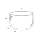
- FIG. 1 is a schematic perspective view showing the configuration of a quartz glass crucible according to an embodiment of the present invention.
- FIG. 2 is a schematic cross-sectional side view of the quartz glass crucible shown in FIG.
- FIG. 3 is a schematic diagram for explaining the impurity concentration distribution in the depth direction from the outer surface of the crucible base.
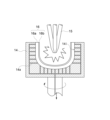
- FIG. 4 is a schematic diagram showing a method for manufacturing a quartz glass crucible by the rotating mold method.
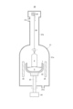
- FIG. 5 is a diagram for explaining the single crystal pulling process using a vitreous silica crucible according to this embodiment, and is a schematic cross-sectional view showing the configuration of a single crystal pulling apparatus.
- FIG. 6 is a schematic cross-sectional side view showing the crystallization state of a quartz glass crucible due to heating.
- FIG. 1 is a schematic perspective view showing the configuration of a quartz glass crucible according to an embodiment of the present invention.
- FIG. 2 is a schematic side cross-sectional view of the quartz glass crucible shown in FIG. 1.
- the quartz glass crucible 1 is a container made of silica glass for holding silicon melt, and has a cylindrical side wall 10a, a bottom 10b provided below the side wall 10a, and a corner 10c provided between the side wall 10a and the bottom 10b.
- the bottom 10b is preferably a gently curved round bottom, but may also be a flat bottom.
- the corner 10c is a portion that has a larger curvature than the bottom 10b.
- the boundary position between the side wall 10a and the corner 10c and the boundary position between the bottom 10b and the corner 10c are positions where the curvature begins to change from a small curvature to a large curvature.
- the aperture (diameter) of the quartz glass crucible 1 varies depending on the diameter of the silicon single crystal ingot pulled from the silicon melt, but is generally 18 inches (approximately 450 mm) or more, preferably 22 inches (approximately 560 mm) or more, and particularly preferably 32 inches (approximately 800 mm) or more. This is because such large crucibles are used to pull large silicon single crystal ingots with diameters of 300 mm or more, and are required to be used for long periods of time without affecting the quality of the single crystal.
- the thickness of the crucible varies slightly depending on the part, but is preferably 6 to 20 mm.
- the thickness of the side wall 10a of a crucible of 18 inches or more is 6 mm or more
- that of the side wall 10a of a crucible of 22 inches or more is 7 mm or more
- that of the side wall 10a of a crucible of 32 inches or more is 10 mm or more. This allows a large amount of molten silicon to be stably held at high temperatures.
- the thickness of the crucible is thickest at the corner parts 10c, and that the side wall parts 10a and bottom part 10b are thinner than the corner parts 10c.
- the quartz glass crucible 1 comprises a crucible base 10 made of silica glass and a coating film 13 containing a crystallization promoter formed on the outer surface 10o of the crucible base 10.
- the crucible base 10 mainly has a two-layer structure, and has a transparent layer 11 (bubble-free layer) that does not contain bubbles and a bubble layer 12 (opaque layer) that contains a large number of tiny bubbles, and the coating film 13 containing a crystallization promoter is provided on the outside of the bubble layer 12.
- the transparent layer 11 is a glass layer constituting the inner surface 10i of the crucible base 10 that comes into contact with the silicon melt, and is provided to prevent a decrease in the yield of silicon single crystals due to bubbles in the silica glass. Since the inner surface 10i of the crucible base 10 reacts with the silicon melt and melts, the bubbles near the inner surface cannot be confined in the silica glass, and there is a risk that the bubbles will burst due to thermal expansion and crucible fragments (silica fragments) will peel off. If the crucible fragments released into the silicon melt are carried by the melt convection to the growth interface of the silicon single crystal and are incorporated into the silicon single crystal, they will cause dislocations in the silicon single crystal. Also, if the bubbles released into the silicon melt float up to the solid-liquid interface and are incorporated into the single crystal, they will cause pinholes to occur in the silicon single crystal.
- the transparent layer 11 being bubble-free means that it has a bubble content and bubble size that are not such that the rate of single crystallization is reduced due to bubbles.
- the bubble content is 0.1 vol% or less
- the bubble diameter is 100 ⁇ m or less.
- the transparent layer 11 is preferably 0.5 to 10 mm thick, and is set to an appropriate thickness for each part of the crucible so that it does not disappear completely due to melting during the crystal pulling process, thereby exposing the bubble layer 12.
- the transparent layer 11 is preferably provided over the entire crucible from the side wall 10a to the bottom 10b, but it is also possible to omit the transparent layer 11 at the upper end of the crucible that does not come into contact with the silicon melt.
- the bubble content and bubble diameter of the transparent layer 11 can be measured non-destructively using optical detection means.
- the optical detection means includes a light receiving device that receives the transmitted or reflected light of the light irradiated to the crucible.
- the light receiving device can be a digital camera including an optical lens and an image sensor.
- the irradiated light can be visible light, ultraviolet light, infrared light, X-rays, laser light, etc.
- the measurement results obtained by the optical detection means are input into an image processing device, and the bubble diameter and bubble content per unit volume are calculated.
- the bubble layer 12 is the main glass layer of the crucible base 10 located outside the transparent layer 11, and is provided to increase the heat retention of the silicon melt in the crucible and to distribute the radiant heat from the heater of the single crystal pulling device to heat the silicon melt in the crucible as uniformly as possible. For this reason, the bubble layer 12 is provided over the entire crucible from the side wall portion 10a to the bottom portion 10b.
- the thickness of the bubble layer 12 is approximately equal to the thickness of the crucible base 10 minus the thickness of the transparent layer 11, and varies depending on the part of the crucible.
- the bubble content of the bubble layer 12 is preferably higher than that of the transparent layer 11, greater than 0.1 vol.% and less than 5 vol.%. If the bubble content of the bubble layer 12 is less than 0.1 vol.%, the bubble layer 12 will not be able to exhibit the required heat retention function. If the bubble content of the bubble layer 12 exceeds 5 vol.%, the crucible may be deformed due to thermal expansion of the bubbles, resulting in a decrease in the single crystal yield, and the heat transfer properties may be insufficient. From the viewpoint of the balance between heat retention and heat transfer properties, it is particularly preferable that the bubble content of the bubble layer 12 is 1 to 4 vol.%.
- the above-mentioned bubble content is a value measured for an unused crucible in a room temperature environment.
- the bubble content of the bubble layer 12 can be determined, for example, by measuring the specific gravity (Archimedes method) of an opaque silica glass piece cut out from the crucible.
- Figure 3 is a schematic diagram illustrating the impurity concentration distribution in the depth direction from the outer surface 10o of the crucible base 10.
- the Al concentration in the first depth region D1 within at least 10 mm from the outer surface 10o of the crucible base 10 is preferably higher than the Fe and Ca concentrations in the first depth region D1. If the Al concentration in the outer surface layer within 10 mm from the outer surface 10o of the crucible base 10 is lower than the Ca and Fe concentrations, the crystallization promoter applied to the outer surface 10o of the crucible base 10 is less likely to be trapped by Al, and crystallization in the in-plane direction is promoted more than crystallization in the depth direction. In order to promote crystallization in the depth direction to a thickness that achieves the strength development effect of the crucible, it is desirable to increase the Al concentration in the wall to a level where it acts as an impurity that serves as the starting point for crystallization.
- the B concentration is 0.02 to 0.05 ppm
- the Mg concentration is 0.02 to 0.4 ppm
- the Cr concentration is 0.02 to 0.08 ppm.
- the concentrations of B, Mg, and Cr in the second depth region D2, which is within 2/3 of the thickness W of the crucible base 10 from the outer surface 10o of the crucible base 10, are preferably higher than the concentrations of B, Mg, and Cr in the third depth region D3, which is within 2 mm from the inner surface 10i of the crucible base 10.
- the thickness of the crucible base 10 here means the thickness at the measurement position of B, Mg, and Cr.
- the carbon susceptor that supports the quartz glass crucible during the crystal pulling process is composed of multiple parts combined together, and the split carbon susceptor has joints (grooves) between the parts on the inner surface.
- the outer surface 10o of the crucible base 10 may soften before crystallizing at high temperatures and bite into the gaps at the joints of the split carbon susceptor. When such bite occurs, the outer surface 10o of the crucible base 10 deforms along the seam, and at the same time, deformation of the inner surface 10i of the crucible base 10 is also induced.
- the concentrations of B, Mg, and Cr on the inner surface 10i of the crucible base 10 it is possible to prevent a decrease in the viscosity of the silica glass and suppress deformation of the inner surface of the crucible.
- the fictive temperature T 1 (° C.) of the outer surface 10o of the crucible base 10 is preferably 50° C. or more lower (T 1 ⁇ T 2 -50) than the fictive temperature T 2 (° C.) inside the base 5 mm deep from the outer surface 10o.
- T 1 ⁇ T 2 -50 the fictive temperature T 1 of the outer surface 10o of the crucible base 10
- T 1 ⁇ T 2 -50 The fictive temperature T 1 (° C.) of the outer surface 10o of the crucible base 10 is preferably 50° C. or more lower (T 1 ⁇ T 2 -50) than the fictive temperature T 2 (° C.) inside the base 5 mm deep from the outer surface 10o.
- T 1 of the outer surface 10o of the crucible base 10 is equal to or slightly lower than the fictive temperature T 2 of the inside, the diffusion of the crystallization promoter and the replacement of the Si-O bond are difficult to occur, and an outer surface crystal layer having a sufficient thickness to
- the Si-O bond is more easily broken on the outer surface 10o than on the inside of the crucible base 10, and the diffusion of the crystallization promoter and the replacement of the Si-O bond are more easily caused, which is effective in promoting crystallization.
- the fictive temperature of the silica glass that constitutes the crucible base 10 can be measured by Raman spectroscopy or FT-IR.
- Raman spectroscopy the surface of the sample to be measured is irradiated with laser light, and the area intensity ratio of the peak derived from the three-membered ring, which is a ring structure of Si, to the peak derived from the four-membered ring is obtained from the Raman (scattering) spectrum.
- the fictive temperature of the sample can be calculated by plotting the obtained results on a calibration curve obtained from the measurement of a sample with a known fictive temperature.
- the peak wavelength derived from the quartz glass structure is detected from the transmission spectrum when laser light is irradiated onto a thin sample of the glass to be measured.
- the fictive temperature of the sample can be calculated by plotting the results on a calibration curve obtained from measuring a sample with a known fictive temperature.
- the outer surface 10o of the crucible base 10 is provided with a coating film 13 containing a crystallization promoter.
- the crystallization promoter contained in the coating film 13 promotes crystallization of the outer surface of the crucible at high temperatures during the single crystal pulling process, thereby improving the strength of the crucible.
- the reason for providing the coating film 13 containing a crystallization promoter on the outer surface side of the crucible is as follows.
- the coating film 13 containing a crystallization promoter is provided on the inner surface of the crucible, there is a risk of contamination of the single crystal due to impurity contamination of the inner surface of the crucible, but since impurity contamination of the outer surface of the crucible is tolerable to a certain extent, the risk of contamination of the single crystal due to the coating film 13 containing a crystallization promoter on the outer surface of the crucible is low.
- the crystallization promoter-containing coating film 13 is provided on the entire crucible from the side wall portion 10a to the bottom portion 10b, but it is sufficient that it is provided at least on the side wall portion 10a. This is because the side wall portion 10a is more easily deformed than the corner portion 10c and the bottom portion 10b, and the effect of suppressing deformation of the crucible by crystallization of the outer surface is also large.
- the crystallization promoter-containing coating film 13 is preferably provided not only on the side wall portion 10a but also on the corner portion 10c.
- the crystallization promoter-containing coating film 13 may or may not be provided on the bottom portion 10b of the crucible. This is because the bottom portion 10b of the crucible receives the weight of a large amount of silicon melt, so it easily fits the carbon susceptor and is less likely to create a gap between the carbon susceptor and the bottom portion 10b.
- the upper end of the rim on the outer surface of the side wall 10a of the crucible, extending 1 to 3 cm downward from the upper end of the rim, may be left as a region where the crystallization promoter-containing coating film 13 is not formed. This makes it possible to suppress crystallization of the upper end surface of the rim, and to prevent dislocations in the silicon single crystal caused by crystal pieces peeling off from the upper end surface of the rim being mixed into the silicon melt.
- the crystallization promoter contained in the crystallization promoter-containing coating film 13 is preferably Ba (barium) or Sr (strontium), with Ba being particularly preferred. This is because Ba has a smaller segregation coefficient than silicon, is stable at room temperature, and is easy to handle. Ba also has the advantage that the crystallization rate does not decrease with crystallization, and induces more oriented growth than other elements.
- the crystallization promoter-containing coating film 13 contains barium carbonate and a thickener, and the concentration of Ba contained in the crystallization promoter-containing coating film 13 is preferably 1.0 ⁇ 10 15 to 1.0 ⁇ 10 18 atoms/cm 2 , and particularly preferably 1.0 ⁇ 10 16 to 1.0 ⁇ 10 17 atoms/cm 2. If the Ba concentration is lower than 1.0 ⁇ 10 15 atoms/cm 2 , the thickness of the outer crystal layer and the range of crystallization may be uneven, and the outer crystal layer may not be formed to a sufficient thickness to improve strength.
- the crystallization of the outer surface may proceed excessively, increasing the probability of cracks occurring in the outer crystal layer.
- the Ba concentration is within the above range, such problems can be avoided, and the crystallization of the outer surface can be promoted while suppressing foaming and peeling of the outer crystal layer.
- the thickness of the crystallization promoter-containing coating film 13 is not particularly limited, but is preferably 0.1 to 50 ⁇ m, and particularly preferably 1 to 20 ⁇ m. If the thickness of the crystallization promoter-containing coating film 13 is too thin, the peel strength of the crystallization promoter-containing coating film 13 will be weak, and peeling of the coating film will cause uneven crystallization. If the coating film is too thick, the peel strength will be reduced and crystallization will be uneven.
- the length of crystal growth (crystallization length) proceeding in the depth direction from the outer surface 10o of the crucible base 10 from the start of heat treatment until 10 hours later is 0.21 to 0.5 mm.
- the thickness of the outer surface crystal layer formed on the outer surface 10o of the crucible base 10 after 10 hours is 210 to 500 ⁇ m.
- the crystallization rate 10 hours after the start of heat treatment is 21 to 50 ⁇ m/hr, but the crystallization rate after 20 hours from the start of heat treatment is 10 ⁇ m/hr or less.
- the crystallization rate of the outer surface is faster than 50 ⁇ m/hr in the early stages of crystallization, there is a risk of foaming and peeling of the outer surface crystal layer.
- the crystallization rate is slower than 21 ⁇ m/hr, the crystallization of the outer surface is insufficient and the desired strength of the crucible cannot be expressed.
- it is possible to form an outer crystal layer of sufficient thickness without causing foaming or peeling of the outer crystal layer, thereby achieving the desired strength of the crucible.
- 10 hours from the start of heat treatment refers to the time when all of the polycrystalline silicon raw material in the crucible has melted and stress begins to be applied to the crucible wall. If the timing at which the outer crystal layer reaches a sufficient thickness is delayed beyond this, the probability of the crucible deforming increases.
- the crystallization rate 10 hours after the start of heat treatment is the thickness of the outer crystal layer after 10 hours divided by the heat treatment time (10 hours), and is calculated as the average crystallization rate over 10 hours.
- the crystallization rate 20 hours or more after the start of heat treatment is the difference between the thickness of the outer crystal layer after 20 hours and the thickness of the outer crystal layer after 30 hours divided by the heat treatment time (10 hours), and is calculated as the average crystallization rate over 10 hours.
- the crystallization rate slows down 15 hours after the start of heat treatment, and that the crystallization rate after 20 hours from the start of heat treatment is 10 ⁇ m/hr or less. If the crystallization rate after 20 hours from the start of heat treatment is greater than 10 ⁇ m/hr, the thickness of the outer crystal layer becomes too thick, and there is a risk that the crystal layer will crack during crystal pulling. By slowing down the crystallization rate after melting the polycrystalline raw material, not only can the strength of the crucible be developed early, but the strength can also be maintained.
- the thickness of the outer crystal layer formed on the outer surface 10o of the crucible base 10 25 hours after the start of the above-mentioned 1580°C heat treatment is preferably about 210 to 600 ⁇ m, and particularly preferably 210 to 500 ⁇ m. If the thickness of the outer crystal layer is thinner than 210 ⁇ m 25 hours after the start of the single crystal pulling process, the probability of the crucible deforming due to insufficient strength increases. If the thickness of the outer crystal layer is thicker than 500 ⁇ m, the adhesion between the crucible and the carbon susceptor becomes poor, and the thermal conductivity between the carbon susceptor and the quartz glass crucible fluctuates during the crystal pulling process, adversely affecting the control of the oxygen concentration and crystal diameter of the silicon single crystal.
- the outer crystal layer becomes too thick, it will foam and peel off, adversely affecting the pulling of the single crystal.
- the thickness of the crystal layer is within the above range, the crucible can develop strength after it becomes accustomed to the carbon susceptor, and the oxygen concentration and crystal diameter of the silicon single crystal can be stably controlled.
- the concentration of the crystallization promoter determines the final thickness of the outer crystal layer.
- concentration of the crystallization promoter determines the final thickness of the outer crystal layer.
- point-like crystal nuclei In the crystallization of the outer surface of the crucible, point-like crystal nuclei (baby nuclei) first occur.
- the crystal nuclei grow over heating time, merging with other nearby crystal nuclei in the process to form a planar crystal layer.
- the planar crystal layer will become thick without peeling off.
- the crystal layer reaches a strength level too quickly, foaming, peeling, and cracks are likely to occur, and conversely, if crystallization is too slow, the crucible will deform before strength is developed.
- the quartz glass crucible of this embodiment optimizes the crystallization rate by promoting crystallization in the depth direction of the outer surface by adjusting factors other than the concentration of the crystallization promoter, namely the virtual temperature gradient in the depth direction from the outer surface and the concentration of metal impurities such as Ca and Fe, so that a sufficiently thick outer surface crystal layer can be formed to increase the strength of the crucible while preventing the occurrence of foaming peeling and cracks.
- the quartz glass crucible 1 can be manufactured by manufacturing the crucible base 10 by the so-called rotational molding method, and then applying a crystallization promoter to the outer surface 10o of the crucible base 10.
- Figure 4 is a schematic diagram showing a method for manufacturing a quartz glass crucible using the rotating mold method.
- a carbon mold 14 is prepared with a cavity that matches the outer shape of the crucible, and natural quartz powder 16a and synthetic quartz powder 16b are filled in sequence along the inner surface 14i of the rotating carbon mold 14 to form a deposition layer 16 of raw quartz powder.
- the raw quartz powder remains in a fixed position attached to the inner surface 14i of the carbon mold 14 by centrifugal force, and the crucible shape is maintained.
- a carbon arc electrode 15 is placed inside the carbon mold 14, and the deposition layer 16 of the raw quartz powder is arc-melted from inside the carbon mold 14.
- Specific conditions such as heating time and heating temperature are appropriately determined taking into account the characteristics of the raw quartz powder, the size of the crucible, etc.
- the amount of bubbles in the molten quartz glass is controlled by suctioning the deposited layer 16 of the raw quartz powder through a number of vents 14a provided on the inner surface 14i of the carbon mold 14. Specifically, at the start of arc melting, the deposited layer 16 of the raw quartz powder is suctioned to form a transparent layer 11, and after the transparent layer 11 is formed, the vacuum suction on the raw quartz powder is stopped or the suction force is weakened to form a bubble layer 12.
- the arc heat travels from the inside to the outside of the deposited layer 16 of raw quartz powder, melting the raw quartz powder, so the transparent layer 11 and the bubble layer 12 can be created by changing the decompression conditions when the raw quartz powder begins to melt.
- reduced-pressure melting is performed in which the decompression is strengthened when the raw quartz powder melts, the atmospheric gas is not trapped in the glass, and the molten quartz becomes silica glass that does not contain bubbles.
- normal melting atmospheric pressure melting
- the atmospheric gas is trapped in the glass, and the molten quartz becomes silica glass that contains many bubbles.
- the raw material with a high Al impurity concentration may be filled outside the region that will become the outer surface 10o of the crucible base 10 after arc melting, and Al may be diffused during arc melting to the region that will become the outer surface 10o of the crucible base 10.
- the raw material with a high Al impurity concentration may also be removed after arc melting. Either method can make the Al concentration high and the Ca and Fe concentrations low near the outer surface 10o of the crucible base 10, which can promote crystallization in the thickness direction rather than in the in-plane direction.
- the fictive temperature changes depending on the cooling temperature of the glass.
- the fictive temperature of the quartz glass becomes high, and when it is cooled slowly, the fictive temperature of the quartz glass becomes low.
- the arc electrode 15, which is the heat source during arc melting, is located on the inner surface of the crucible, so cooling of the inner surface of the crucible begins immediately after the arc ends.
- the carbon mold 14 is present on the outer surface of the crucible, and the carbon mold remains at a high temperature even after the arc ends.
- the cooling rate of the outer surface 10o side of the crucible base 10 becomes slower than that of the inner surface 10i side.
- the outer surface 10o side of the crucible base 10 is cooled more slowly than the inner surface 10i side, so the fictive temperature of the outer surface 10o becomes lower than that of the inside.
- the heat retention of the carbon mold 14 is increased by heating, etc., and the cooling rate of the outer surface 10o side of the crucible base 10 is slowed down, so that the virtual temperature difference between the outer surface 10o of the crucible base 10 and the inside of the base is increased by 50°C or more.
- the crucible base 10 in which the transparent layer 11 and the bubble layer 12 are provided in sequence from the inside to the outside of the crucible wall.
- the crucible base 10 according to this embodiment can be manufactured by filling a rotating carbon mold 14 with natural quartz powder 16a as the outer layer raw material, then filling it with synthetic quartz powder 16b as the inner layer raw material, and arc melting the deposition layer 16 of the raw quartz powder.
- the cleaning solution is preferably prepared by diluting hydrofluoric acid of semiconductor grade or higher with pure water of TOC ⁇ 2 ppb to 10-40 wt %.
- a crystallization promoter is applied to the outer surface 10o of the crucible base 10. It is preferable to use a brush to apply the coating liquid. In order to uniformly disperse the crystallization promoter on the outer surface 10o, it is preferable to use a coating liquid in which the crystallization promoter is dissolved in pure water (15-25°C, 17.2 M ⁇ or more, TOC ⁇ 2 ppb). In order to increase the solubility of the crystallization promoter, it is preferable to stir the coating liquid using a stirrer.
- a solution containing a barium compound such as barium carbonate
- the coating solution containing a barium compound may be a coating solution consisting of a barium compound and water, or may be a coating solution containing anhydrous ethanol and a barium compound without water.
- barium compound barium carbonate is preferred, but other barium compounds such as barium chloride, barium acetate, barium nitrate, barium hydroxide, barium oxalate, and barium sulfate may also be used.
- the crystallization promotion effect is the same regardless of whether it is insoluble or water-soluble, but water-insoluble barium is less likely to be taken into the human body, so it is safer and more advantageous in terms of handling.
- the coating solution containing a barium compound preferably further contains a highly viscous water-soluble polymer (thickener) such as carboxyvinyl polymer.
- thickener such as carboxyvinyl polymer.
- the barium is not attached to the crucible wall surface in an stable manner, and heat treatment is required to fix the barium.
- heat treatment is performed, the barium diffuses and penetrates into the inside of the quartz glass, which promotes random crystal growth.
- random growth means that there is no regularity in the direction of crystal growth in the crystal layer, and the crystals grow in all directions. With random growth, crystallization stops at the beginning of heating, so the crystal layer cannot be made thick enough.
- Columnar oriented crystals refer to a crystal layer consisting of a collection of columnar crystal grains.
- dome oriented crystals refer to a crystal layer consisting of a collection of dome shaped crystal grains. Columnar and dome oriented crystals can sustain crystal growth, so a crystal layer with sufficient thickness can be formed.
- Thickeners include water-soluble polymers with low levels of metal impurities, such as polyvinyl alcohol, cellulose-based thickeners, high-purity glucomannan, acrylic polymers, carboxyvinyl polymers, and polyethylene glycol fatty acid esters.
- acrylic acid/alkyl methacrylate copolymers, polyacrylates, polyvinyl carboxylic acid amides, and vinyl carboxylic acid amides may also be used as thickeners.
- the viscosity of the coating solution containing barium is preferably in the range of 100 to 10,000 mPa ⁇ s, and the boiling point of the solvent is preferably 50 to 100°C.
- a crystallization promoter coating solution for coating the exterior surface of a 32-inch crucible contains 0.0012 g/mL barium carbonate and 0.0008 g/mL carboxyvinyl polymer, and can be prepared by adjusting the ratio of ethanol to pure water and mixing and stirring them.
- FIG. 5 is a diagram for explaining the single crystal pulling process using the quartz glass crucible 1 according to this embodiment, and is a schematic cross-sectional view showing the configuration of a single crystal pulling device.
- a single crystal pulling device 20 is used in the silicon single crystal pulling process using the CZ method.
- the single crystal pulling device 20 includes a water-cooled chamber 21, a quartz glass crucible 1 that holds silicon melt in the chamber 21, a carbon susceptor 22 that holds the quartz glass crucible 1, a rotating shaft 23 that supports the carbon susceptor 22 so that it can rotate and rise and fall, a shaft drive mechanism 24 that drives the rotating shaft 23 to rotate and rise and fall, a heater 25 arranged around the carbon susceptor 22, a single crystal pulling wire 28 arranged above the quartz glass crucible 1 and coaxially with the rotating shaft 23, and a wire winding mechanism 29 arranged above the chamber 21.
- the chamber 21 is composed of a main chamber 21a and a long, cylindrical pull chamber 21b connected to the upper opening of the main chamber 21a, and the quartz glass crucible 1, carbon susceptor 22, and heater 25 are provided in the main chamber 21a.
- a gas inlet 21c is provided at the top of the pull chamber 21b to introduce an inert gas (purge gas) such as argon gas or a dopant gas into the main chamber 21a, and a gas outlet 21d is provided at the bottom of the main chamber 21a to exhaust the atmospheric gas in the main chamber 21a.
- the carbon susceptor 22 is used to maintain the shape of the quartz glass crucible 1 that has softened under high temperatures, and holds the quartz glass crucible 1 in a wrapped state.
- the quartz glass crucible 1 and the carbon susceptor 22 form a double-structure crucible that supports the silicon melt within the chamber 21.
- the carbon susceptor 22 is fixed to the upper end of a rotating shaft 23, and the lower end of the rotating shaft 23 passes through the bottom of the chamber 21 and is connected to a shaft drive mechanism 24 provided outside the chamber 21.
- the heater 25 is used to melt the polycrystalline silicon raw material filled in the quartz glass crucible 1 to produce silicon melt 3, and to maintain the molten state of the silicon melt 3.
- the heater 25 is a resistance heating carbon heater, and is provided so as to surround the quartz glass crucible 1 inside the carbon susceptor 22.
- the wire winding mechanism 29 is located above the pull chamber 21b, and the wire 28 extends downward from the wire winding mechanism 29 through the pull chamber 21b, with the tip of the wire 28 reaching the internal space of the main chamber 21a.
- This figure shows a silicon single crystal 2 in the process of being grown suspended from the wire 28.
- the quartz glass crucible 1 and the silicon single crystal 2 are rotated while the wire 28 is gradually pulled up to grow the silicon single crystal 2.
- the quartz glass crucible 1 is raised so that the height of the melt surface remains constant. This makes it possible to stabilize the crystal quality in the direction of crystal growth.
- Figure 6 is a schematic cross-sectional side view showing the crystallization state of a quartz glass crucible due to heating.
- an outer crystal layer 31 is formed on the outer surface 10o of the quartz glass crucible 1 during the crystal pulling process.
- the Ba concentration in the outer crystal layer 31 formed on the outer surface 10o of the crucible base 10 by heating during the crystal pulling process or an equivalent heat treatment is preferably less than 10 ppm. If the Ba concentration in the outer crystal layer 31 is 10 ppm or more, the concentration of the crystallization promoter applied to the outer surface 10o of the crucible base 10 is high, so that crystallization of the outer surface 10o is excessively promoted, and foaming and peeling of the outer crystal layer 31 are likely to occur. However, if the Ba concentration in the outer crystal layer 31 is less than 10 ppm, it is possible to promote crystallization of the outer surface while suppressing foaming and peeling of the outer crystal layer 31.
- the quartz glass crucible 1 comprises a crucible base 10 made of silica glass and a coating film 13 containing a crystallization promoter formed on the outer surface 10o of the crucible base 10, and 10 hours after the start of heat treatment in a furnace with an internal temperature of 1580°C, an internal pressure of 20 Torr, and an Ar atmosphere, the length of crystal growth proceeding in the depth direction from the outer surface 10o of the crucible base 10 is 0.21 to 0.5 mm, the crystallization rate is 21 to 50 ⁇ m/hr, and the crystallization rate of the outer surface 10o 20 hours or more after the start of heat treatment is 10 ⁇ m/hr or less.
- the fictive temperature of the outer surface 10o of the crucible base 10 is 50°C lower than the fictive temperature inside at a depth of 5 mm from the outer surface 10o, so not only can it promote crystallization of the outer surface of the crucible, but the crystallization of the outer surface of the crucible is neither too fast nor too slow, and it has an appropriate strength development time. Therefore, not only can it withstand the long single crystal pulling process, but it can also stably control the oxygen concentration and crystal diameter of the silicon single crystal by minimizing the gap with the carbon susceptor.
- crucible bases with different metal impurity concentrations on the outer surface were prepared, and a barium carbonate solution was applied to part of the outer surface of the crucible base with a brush, after which the crucible was crushed into small pieces.
- a metal impurity analysis was performed in the depth direction from the outer surface of the crucible base using multiple crucible pieces obtained from the same crucible base that had not been coated with barium carbonate.
- the silica glass was dissolved to a certain depth from the outer surface of the crucible by wet etching, and the etching solution was recovered and the amount of metal impurities dissolved in the etching solution was measured using ICP-MS (Inductively Coupled Plasma-Mass Spectrometry).
- the first measurement range was from the outer surface of the crucible base to a depth of 5 mm
- the second measurement range was from a depth of 5 to 10 mm
- the third measurement range was from a depth of 10 to 15 mm.
- the measurement results are shown in Tables 1 and 2.
- the Fe and Al concentration profiles of the crucible base of Comparative Example 1 showed that the Fe concentration was higher throughout the entire depth range from the outer surface to 15 mm, and the relationship Fe concentration > Al concentration was established. Furthermore, the Fe and Al concentration profiles of the crucible base of Comparative Example 2 showed that the Fe concentration ⁇ Al concentration was established in the depth range from the outer surface to 5 mm, and the relationship Fe concentration > Al concentration was established in the depth range from 5 to 15 mm. In contrast, the Fe and Al concentration profiles of the crucible base of Example 1 showed that the Fe concentration ⁇ Al concentration was established in the depth range from the outer surface to 10 mm, and the relationship Fe concentration > Al concentration was established in the depth range from 10 to 15 mm. Furthermore, the crucible base of Example 2 showed that the Fe concentration ⁇ Al concentration was established throughout the entire depth range from the outer surface to 15 mm.
- the Ca concentration profile also showed a similar tendency to Fe. That is, in the Ca and Al concentration profiles of the crucible base of Comparative Example 1, the Ca concentration was higher in the entire area from the outer surface to 15 mm in the depth direction, and the relationship of Ca concentration > Al concentration was established. In addition, in the Ca and Al concentration profiles of the crucible base of Comparative Example 2, the relationship of Ca concentration ⁇ Al concentration was established in the area from the outer surface to 5 mm in the depth direction, and the relationship of Ca concentration > Al concentration was established in the area from 5 to 15 mm in the depth direction.
- the Fe concentration and Ca concentration in the depth region from the outer surface to a depth of 10 mm were higher than the Al concentration, whereas in the crucible samples of Examples 1 and 2, the Al concentration in the depth region from the outer surface to a depth of 10 mm was lower than the Fe concentration and Ca concentration.
- the measurement range was set to a depth region from the outer surface to 2/3 of the crucible thickness, and after dissolving the silica glass by wet etching, the etching solution was recovered and the amount of metal impurities dissolved in the etching solution was measured by ICP-MS.
- the measurement results are shown in Table 3.
- the B concentration of the crucible base of Comparative Example 1 was 0.1 ppm.
- the B concentration of the crucible base of Comparative Example 2 was 0.01 ppm.
- the B concentration profile of the crucible base of Example 1 was 0.02 ppm, and the B concentration of the crucible base of Example 2 was 0.05 ppm.
- the Mg concentration of the crucible base of Comparative Example 1 was 0.5 ppm.
- the Mg concentration of the crucible base of Comparative Example 2 was 0.01 ppm.
- the Mg concentration profile of the crucible base of Example 1 was 0.02 ppm, and the Mg concentration of the crucible base of Example 2 was 0.4 ppm.
- the Cr concentration of the crucible base of Comparative Example 1 was 0.1 ppm.
- the Mg concentration of the crucible base of Comparative Example 2 was 0.01 ppm.
- the Cr concentration of the crucible base of Example 1 was 0.02 ppm, and the Cr concentration of the crucible base of Example 2 was 0.08 ppm.
- the fictive temperature of the outer surface of the crucible base and the fictive temperature inside the base 5 mm deeper than the outer surface were measured by Raman spectroscopy.
- the measurement area for the fictive temperature of the outer surface was a range from 0 mm to 0.5 mm deep from the outer surface.
- the measurement area for the fictive temperature inside the base was a range from 5.0 mm to 5.5 mm deep from the outer surface.
- the fictive temperature difference between the outer surface and the inside of the crucible base is shown in Table 4.
- a heating test was carried out using the crucible pieces coated with barium carbonate.
- a crucible piece with a side length of 10 to 20 cm, an area of 200 cm2 or more, and an aspect ratio as close to 1 as possible was used.
- the heating conditions were as follows: the temperature in the furnace in an Ar atmosphere was raised from room temperature to 1580°C over 2.5 hours, and then the temperature was held at 1580°C for 10 hours. The pressure in the furnace held at 1580°C was 20 Torr.
- the crystallization state of the outer surface of the crucible pieces was evaluated.
- the thickness of the outer crystal layer of the crucible pieces was measured, and the ratio of the thickness of the outer crystal layer to the high-temperature holding time (10 hours) at 1580°C was calculated as the crystallization rate.
- an outer crystal layer with a thickness of 200 ⁇ m or more was judged to have a strength enhancing effect, and one with a thickness of less than 200 ⁇ m was judged to have no strength enhancing effect.
- the crucible samples of Comparative Examples 1 and 2 had a fictive temperature difference of 10°C or less, a crystallization rate of 1 ⁇ m/hr or less, and no strength development effect was obtained.
- the crucible samples of Examples 1 and 2 had a fictive temperature difference of 50°C or more, a crystallization rate of 21 ⁇ m/hr or more, and a strength development effect was obtained. From these results, it was found that when the fictive temperature difference is 50°C or more, an outer surface crystal layer of 200 ⁇ m or more can be formed on the outer surface of the crucible, and a strength development effect can be obtained.
- Silicon single crystals were actually pulled using another crucible manufactured under the same conditions as in Examples 1 and 2 and Comparative Examples 1 and 2, and the state of deformation and peeling of the crucible was visually confirmed.
- Table 4 also shows the results of deformation and peeling of the crucible.
- deformation refers to the result of visually observing and evaluating whether there was any deformation, such as inward collapse of the opening, buckling of the side wall and corner parts, or surface irregularities caused by fitting to the carbon susceptor, before use.
- peeling refers to the result of visually observing and evaluating whether part of the crystal layer formed on the outer surface of the crucible has peeled off due to foaming, deformation, etc., exposing the uncrystallized glass surface.
Landscapes
- Chemical & Material Sciences (AREA)
- Engineering & Computer Science (AREA)
- Organic Chemistry (AREA)
- Materials Engineering (AREA)
- Crystallography & Structural Chemistry (AREA)
- Metallurgy (AREA)
- Life Sciences & Earth Sciences (AREA)
- Chemical Kinetics & Catalysis (AREA)
- General Chemical & Material Sciences (AREA)
- Geochemistry & Mineralogy (AREA)
- Ceramic Engineering (AREA)
- Physics & Mathematics (AREA)
- Thermal Sciences (AREA)
- Manufacturing & Machinery (AREA)
- Crystals, And After-Treatments Of Crystals (AREA)
Priority Applications (5)
| Application Number | Priority Date | Filing Date | Title |
|---|---|---|---|
| US19/142,679 US20260103821A1 (en) | 2023-01-13 | 2023-10-24 | Quartz glass crucible and method for producing silicon single crystal using same |
| KR1020257022286A KR20250119610A (ko) | 2023-01-13 | 2023-10-24 | 석영 유리 도가니 및 이를 이용한 실리콘 단결정의 제조 방법 |
| DE112023005191.7T DE112023005191T5 (de) | 2023-01-13 | 2023-10-24 | Quarzglastiegel und verfahren zur herstellung eines siliziummonokristalls unter verwendung desselben |
| CN202380090999.0A CN120500560A (zh) | 2023-01-13 | 2023-10-24 | 石英玻璃坩埚及使用其的单晶硅的制造方法 |
| JP2024570040A JPWO2024150500A1 (https=) | 2023-01-13 | 2023-10-24 |
Applications Claiming Priority (2)
| Application Number | Priority Date | Filing Date | Title |
|---|---|---|---|
| JP2023003944 | 2023-01-13 | ||
| JP2023-003944 | 2023-01-13 |
Publications (1)
| Publication Number | Publication Date |
|---|---|
| WO2024150500A1 true WO2024150500A1 (ja) | 2024-07-18 |
Family
ID=91896847
Family Applications (1)
| Application Number | Title | Priority Date | Filing Date |
|---|---|---|---|
| PCT/JP2023/038281 Ceased WO2024150500A1 (ja) | 2023-01-13 | 2023-10-24 | 石英ガラスルツボ及びこれを用いたシリコン単結晶の製造方法 |
Country Status (7)
| Country | Link |
|---|---|
| US (1) | US20260103821A1 (https=) |
| JP (1) | JPWO2024150500A1 (https=) |
| KR (1) | KR20250119610A (https=) |
| CN (1) | CN120500560A (https=) |
| DE (1) | DE112023005191T5 (https=) |
| TW (1) | TW202432907A (https=) |
| WO (1) | WO2024150500A1 (https=) |
Citations (3)
| Publication number | Priority date | Publication date | Assignee | Title |
|---|---|---|---|---|
| WO2008149781A1 (ja) * | 2007-05-31 | 2008-12-11 | Shin-Etsu Quartz Products Co., Ltd. | シリコン単結晶引上用石英ガラスルツボおよびその製造方法 |
| JP2019059652A (ja) * | 2017-09-27 | 2019-04-18 | クアーズテック株式会社 | シリコン単結晶引上げ用石英ガラスルツボ |
| JP2021050139A (ja) * | 2017-05-02 | 2021-04-01 | 株式会社Sumco | シリコン単結晶の製造方法 |
Family Cites Families (3)
| Publication number | Priority date | Publication date | Assignee | Title |
|---|---|---|---|---|
| KR101863159B1 (ko) | 2016-11-08 | 2018-06-04 | 한국에너지기술연구원 | 양방향 에너지네트워크에서의 복합에너지시스템 및 그 제어방법 |
| JP7379054B2 (ja) | 2018-12-27 | 2023-11-14 | モメンティブ・テクノロジーズ・山形株式会社 | 石英ガラスるつぼの製造方法および光学ガラス溶融用石英ガラスるつぼ |
| JP7375833B2 (ja) | 2020-01-10 | 2023-11-08 | 株式会社Sumco | 石英ガラスルツボ |
-
2023
- 2023-10-24 JP JP2024570040A patent/JPWO2024150500A1/ja active Pending
- 2023-10-24 DE DE112023005191.7T patent/DE112023005191T5/de active Pending
- 2023-10-24 WO PCT/JP2023/038281 patent/WO2024150500A1/ja not_active Ceased
- 2023-10-24 CN CN202380090999.0A patent/CN120500560A/zh active Pending
- 2023-10-24 US US19/142,679 patent/US20260103821A1/en active Pending
- 2023-10-24 KR KR1020257022286A patent/KR20250119610A/ko active Pending
- 2023-12-08 TW TW112147867A patent/TW202432907A/zh unknown
Patent Citations (3)
| Publication number | Priority date | Publication date | Assignee | Title |
|---|---|---|---|---|
| WO2008149781A1 (ja) * | 2007-05-31 | 2008-12-11 | Shin-Etsu Quartz Products Co., Ltd. | シリコン単結晶引上用石英ガラスルツボおよびその製造方法 |
| JP2021050139A (ja) * | 2017-05-02 | 2021-04-01 | 株式会社Sumco | シリコン単結晶の製造方法 |
| JP2019059652A (ja) * | 2017-09-27 | 2019-04-18 | クアーズテック株式会社 | シリコン単結晶引上げ用石英ガラスルツボ |
Also Published As
| Publication number | Publication date |
|---|---|
| KR20250119610A (ko) | 2025-08-07 |
| CN120500560A (zh) | 2025-08-15 |
| JPWO2024150500A1 (https=) | 2024-07-18 |
| DE112023005191T5 (de) | 2025-10-09 |
| TW202432907A (zh) | 2024-08-16 |
| US20260103821A1 (en) | 2026-04-16 |
Similar Documents
| Publication | Publication Date | Title |
|---|---|---|
| US20220018037A1 (en) | Quartz glass crucible | |
| JP7070719B2 (ja) | シリコン単結晶の製造方法 | |
| JP7673758B2 (ja) | 石英ガラスルツボ及びその製造方法並びにシリコン単結晶の製造方法 | |
| JP5473878B2 (ja) | シリコン単結晶引き上げ用石英ガラスルツボの製造方法 | |
| TWI754479B (zh) | 石英玻璃坩鍋 | |
| WO2024150500A1 (ja) | 石英ガラスルツボ及びこれを用いたシリコン単結晶の製造方法 | |
| JP7768072B2 (ja) | シリコン単結晶引き上げ用石英ガラスルツボ及びこれを用いたシリコン単結晶の製造方法 | |
| JP7823596B2 (ja) | 石英ガラスルツボ及びその製造方法 | |
| WO2024090073A1 (ja) | シリコン単結晶引き上げ用石英ガラスルツボ及びこれを用いたシリコン単結晶の製造方法 | |
| JP2024043650A (ja) | 石英ガラスルツボ及びその製造方法及び石英ガラスルツボ用石英粉 | |
| WO2022249570A1 (ja) | 石英ガラスルツボ及びその製造方法並びにシリコン単結晶の製造方法 |
Legal Events
| Date | Code | Title | Description |
|---|---|---|---|
| 121 | Ep: the epo has been informed by wipo that ep was designated in this application |
Ref document number: 23916118 Country of ref document: EP Kind code of ref document: A1 |
|
| WWE | Wipo information: entry into national phase |
Ref document number: 2024570040 Country of ref document: JP |
|
| WWE | Wipo information: entry into national phase |
Ref document number: 1020257022286 Country of ref document: KR |
|
| WWE | Wipo information: entry into national phase |
Ref document number: 202380090999.0 Country of ref document: CN |
|
| WWP | Wipo information: published in national office |
Ref document number: 1020257022286 Country of ref document: KR |
|
| WWE | Wipo information: entry into national phase |
Ref document number: 112023005191 Country of ref document: DE |
|
| WWP | Wipo information: published in national office |
Ref document number: 202380090999.0 Country of ref document: CN |
|
| WWE | Wipo information: entry into national phase |
Ref document number: 11202504251V Country of ref document: SG |
|
| WWP | Wipo information: published in national office |
Ref document number: 11202504251V Country of ref document: SG |
|
| WWP | Wipo information: published in national office |
Ref document number: 112023005191 Country of ref document: DE |
|
| 122 | Ep: pct application non-entry in european phase |
Ref document number: 23916118 Country of ref document: EP Kind code of ref document: A1 |