WO2024150409A1 - 画像データ伝送システム、対基板作業機、及び画像データ伝送方法 - Google Patents
画像データ伝送システム、対基板作業機、及び画像データ伝送方法 Download PDFInfo
- Publication number
- WO2024150409A1 WO2024150409A1 PCT/JP2023/000796 JP2023000796W WO2024150409A1 WO 2024150409 A1 WO2024150409 A1 WO 2024150409A1 JP 2023000796 W JP2023000796 W JP 2023000796W WO 2024150409 A1 WO2024150409 A1 WO 2024150409A1
- Authority
- WO
- WIPO (PCT)
- Prior art keywords
- image data
- image
- data
- compressed
- transmission system
- Prior art date
- Legal status (The legal status is an assumption and is not a legal conclusion. Google has not performed a legal analysis and makes no representation as to the accuracy of the status listed.)
- Ceased
Links
Images

Classifications
-
- H—ELECTRICITY
- H04—ELECTRIC COMMUNICATION TECHNIQUE
- H04N—PICTORIAL COMMUNICATION, e.g. TELEVISION
- H04N19/00—Methods or arrangements for coding, decoding, compressing or decompressing digital video signals
- H04N19/90—Methods or arrangements for coding, decoding, compressing or decompressing digital video signals using coding techniques not provided for in groups H04N19/10-H04N19/85, e.g. fractals
-
- H—ELECTRICITY
- H04—ELECTRIC COMMUNICATION TECHNIQUE
- H04N—PICTORIAL COMMUNICATION, e.g. TELEVISION
- H04N21/00—Selective content distribution, e.g. interactive television or video on demand [VOD]
- H04N21/40—Client devices specifically adapted for the reception of or interaction with content, e.g. set-top-box [STB]; Operations thereof
- H04N21/43—Processing of content or additional data, e.g. demultiplexing additional data from a digital video stream; Elementary client operations, e.g. monitoring of home network or synchronising decoder's clock; Client middleware
- H04N21/436—Interfacing a local distribution network, e.g. communicating with another STB or one or more peripheral devices inside the home
-
- H—ELECTRICITY
- H04—ELECTRIC COMMUNICATION TECHNIQUE
- H04N—PICTORIAL COMMUNICATION, e.g. TELEVISION
- H04N23/00—Cameras or camera modules comprising electronic image sensors; Control thereof
- H04N23/60—Control of cameras or camera modules
-
- H—ELECTRICITY
- H05—ELECTRIC TECHNIQUES NOT OTHERWISE PROVIDED FOR
- H05K—PRINTED CIRCUITS; CASINGS OR CONSTRUCTIONAL DETAILS OF ELECTRIC APPARATUS; MANUFACTURE OF ASSEMBLAGES OF ELECTRICAL COMPONENTS
- H05K13/00—Apparatus or processes specially adapted for manufacturing or adjusting assemblages of electric components
- H05K13/08—Monitoring manufacture of assemblages
Definitions
- This disclosure relates to an image data transmission system for transmitting image data, a substrate-related processing machine, and an image data transmission method.
- Patent Document 1 describes a surface mount machine that transmits image data captured by an imaging element through communications conforming to the Camera Link (registered trademark) standard.
- image data is transmitted by connecting a transmitting device and a receiving device with a camera interface standardized according to a standard related to image data, such as the Camera Link standard.
- a communication cable (Camera Link cable) and Camera Link hardware that conform to the standard are used.
- the present disclosure has been made in consideration of the above problems, and aims to provide an image data transmission system, a substrate-related processing machine, and an image data transmission method that can transmit image data at high speed.
- this specification discloses an image data transmission system having an image data acquisition unit that acquires first image data from an imaging element, an image compression processing unit that generates compressed image data by performing lossless image compression on the acquired first image data, and generates second image data by adding predetermined data to the compressed image data until the image size conforms to the Camera Link standard, a transmitting device that transmits the second image data, and a receiving device that receives the second image data from the transmitting device via a communication cable conforming to the Camera Link standard, and has an image decompression processing unit that decompresses the received second image data to generate the first image data.
- the present specification discloses a substrate-related work machine that includes an image data transmission system and performs work on a substrate, the image data transmission system having an image data acquisition unit that acquires first image data from an image sensor, and an image compression processing unit that generates compressed image data by compressing the acquired first image data and generates second image data by adding predetermined data to the compressed image data until the image size reaches a predetermined standard related to the image data, a transmitting device that transmits the second image data, and a receiving device having an image decompression processing unit that receives the second image data from the transmitting device via a communication cable conforming to the predetermined standard and decompresses the received second image data to generate the first image data, the image size of the first image data being the image size set based on an ROI (Region of Interest), and the target area is at least one of the areas of the image data captured by the image sensor that shows an electronic component to be mounted on the substrate and the area that shows a mark provided on the substrate.
- ROI Region of Interest
- this specification discloses an image data transmission method for transmitting image data from a transmitting device to a receiving device, the method including an image data capture step of capturing first image data from an imaging element, an image compression processing step of generating compressed image data by compressing the captured first image data and generating second image data by adding predetermined data to the compressed image data until the image size reaches a predetermined standard related to the image data, a transmission step of transmitting the second image data from the transmitting device, and an image decompression processing step of receiving the second image data from the transmitting device to the receiving device via a communication cable conforming to the predetermined standard and decompressing the received second image data to generate the first image data.
- the disclosed image data transmission system, substrate-related operating machine, and image data transmission method allow for high-speed transmission of image data.
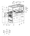
- FIG. 1 is a perspective view showing a schematic configuration of a component mounting machine 10 and a loader 11 according to a first embodiment.
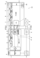
- FIG. 1 is a block diagram of an image data transmission system 41 according to a first embodiment.
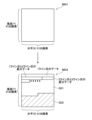
- 3A and 3B are conceptual diagrams of first image data IMG1 and second image data IMG2.
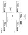
- 5A and 5B are diagrams showing the transmission states of image data in a non-compression mode and a compression mode, and the start timing of image processing, etc.
- FIG. FIG. 11 is a block diagram of an image data transmission system 41A according to a second embodiment.
- Fig. 1 is a perspective view showing a schematic configuration of the component mounting machine 10 and a loader 11.
- the direction in which the component mounting machine 10 in Fig. 1 transports a substrate 13 is referred to as the X direction (left-right direction)
- the direction perpendicular to the X direction and parallel to the substrate plane of the substrate 13 is referred to as the Y direction (front-back direction)
- the direction perpendicular to the X direction and the Y direction is referred to as the Z direction (up-down direction).
- the component mounting machine 10 is provided, for example, in a production line (not shown) in which multiple component mounting machines 10 are connected in the X direction, and transports the board 13 from left to right.
- This production line for example, performs tasks such as mounting electronic components on the transported board 13 by using the multiple component mounting machines 10.
- the component mounting machine 10 includes a base 21 and a module 22.
- the base 21 is fixed to the base of an adjacent component mounting machine (not shown).
- the module 22 is a device that mounts electronic components on the board 13, and is placed on the base 21.
- the module 22 includes a board transport device 23, a feeder table 24, a mounting head 25, a head movement mechanism 27, and a parts camera 28.
- the board transport device 23 is provided within the module 22, and transports the board 13 in the X direction on each of the two lanes.
- the feeder table 24 is provided on the front side of the module 22, and includes a plurality of slots (not shown) arranged in the X direction.
- a feeder 29 e.g., a tape feeder
- FIG. 1 shows the module 22 with the top cover (not shown) and the touch panel (not shown) provided on the top cover removed.
- the mounting head 25 has a holding member 25A that holds the electronic components supplied from the feeder 29.
- the holding member 25A may be a suction nozzle that is supplied with negative pressure to hold the electronic components, or a chuck that grips and holds the electronic components.
- the mounting head 25 has, for example, a plurality of servo motors 82 (see FIG. 2) as a drive source that changes the overall position of the plurality of holding members 25A or the position of each of the holding members 25A. Note that in FIG. 2, the plurality of servo motors 82 are illustrated as one unit to avoid cluttering the drawing.
- the mounting head 25 rotates a holder that holds the plurality of holding members 25A, rotates each of the plurality of holding members 25A around an axis along the Z direction, or raises and lowers the holding members 25A in the vertical direction.
- the mounting head 25 mounts the electronic components held by the holding members 25A onto the board 13.
- the head movement mechanism 27 also moves the mounting head 25 to any position in the X and Y directions in the upper portion of the module 22. More specifically, the head movement mechanism 27 includes an X-axis slide mechanism 27A that moves the mounting head 25 in the X direction, and a Y-axis slide mechanism 27B that moves the mounting head 25 in the Y direction. The X-axis slide mechanism 27A is attached to the Y-axis slide mechanism 27B.
- the Y-axis slide mechanism 27B has a linear motor (not shown) as a drive source.
- the X-axis slide mechanism 27A moves to any position in the Y direction based on the drive of the linear motor of the Y-axis slide mechanism 27B.
- the X-axis slide mechanism 27A also has a linear motor (not shown) as a drive source.
- the mounting head 25 is attached to the X-axis slide mechanism 27A, and moves to any position in the X direction based on the drive of the linear motor of the X-axis slide mechanism 27A. Therefore, the mounting head 25 moves to any position in the X and Y directions within the module 22 in conjunction with the drive of the X-axis slide mechanism 27A and the Y-axis slide mechanism 27B.
- the mounting head 25 is attached to the X-axis slide mechanism 27A via a connector and can be attached and detached with a single touch, allowing the mounting head 25 to be changed to one with different performance and functions. Therefore, the mounting head 25 is detachable from the component mounting machine 10.
- a mark camera 69 for photographing the board 13 is fixed to the X-axis slide mechanism 27A facing downward. The mark camera 69 can photograph any position on the board 13 from above as the mounting head 25 moves. Image data captured by the mark camera 69 is transmitted from the X-axis slide mechanism 27A to the control device 43 (see FIG. 2) of the component mounting machine 10, and image processed by the image processing PC 51 of the control device 43.
- the image processing PC 51 obtains information about the board 13 (such as information about the mark indicating the board type) by, for example, image processing the image data of the mark camera 69.
- the image processing PC 51 for example, processes the image data from the mark camera 69 to obtain the error in the holding position of the board and correct the position of the electronic component held by the mounting head 25.
- the mounting head 25 is also provided with an IPS camera 81 (see FIG. 2) that captures an image of the electronic component held by the holding member 25A.
- the IPS camera 81 is a side camera that captures an image of the electronic component held by the holding member 25A of the mounting head 25 from the side.
- the IPS camera 81 is an imaging device that outputs image data by communication conforming to the Camera Link (registered trademark) standard, for example.
- the IPS camera 81 is provided with a CMOS sensor 81A as an imaging element. Note that the imaging element of the present disclosure is not limited to a CMOS sensor, and may be other imaging elements such as a CCD sensor.
- the image data captured by the IPS camera 81 is transmitted from the mounting head 25 to the control device 43 by multiplex communication described later, and is image-processed by the image processing PC 51 (see FIG. 2) of the control device 43.
- the image processing PC 51 acquires, by image processing, an error in the holding position of the electronic component on the holding member 25A, etc.
- the parts camera 28 is disposed between the feeder table 24 and the board transport device 23 in the front-rear direction, and is fixed with its imaging direction facing upward.
- the parts camera 28 images the electronic components held by the holding member 25A from below.
- the image processing PC 51 processes the image data captured by the parts camera 28 to obtain errors in the holding position of the electronic components on the holding member 25A.
- the component mounting machine 10 may be configured to include at least one of the IPS camera 81 and the parts camera 28.
- the feeder 29 is automatically replaced by the loader 11 moving on the production line.
- an upper guide rail 31 and a lower guide rail 33 extending in the X-axis direction, a rack gear 35, and a non-contact power supply coil 37 are provided on the front side of the base 21.
- Each of the upper guide rail 31, the lower guide rail 33, and the rack gear 35 is connected to the upper guide rail 31, etc. of an adjacent component mounting machine (not shown).
- the non-contact power supply coil 37 supplies power to the loader 11.
- the loader 11 has a gripping portion (not shown) that clamps the feeder 29, and rollers that are inserted into the upper guide rail 31 and the lower guide rail 33, and moves in the X-axis direction by rotating a gear that meshes with the rack gear 35 based on the drive of the motor.
- the loader 11 receives power from a non-contact power supply coil 37 to drive the motor.
- the control device 43 of the component mounting machine 10 is connected to, for example, a host computer that provides overall management of the production line. Based on the control of this host computer, the loader 11 replenishes and collects the feeders 29 for the multiple component mounting machines 10 lined up on the production line.
- the component mounting machine 10 may be configured so that the user can manually replace the feeders 29.
- FIG. 2 is a block diagram showing the configuration of the image data transmission system 41.
- the image data transmission system 41 includes a control device 43 and a component mounting unit 44.
- the control device 43 is an example of a receiving device of the present disclosure.
- the component mounting unit 44 is an example of a transmitting device of the present disclosure.
- the transmitting device of the present disclosure employs a CMOS sensor 81A provided in the IPS camera 81 of the mounting head 25 as an imaging element that captures the first image data.
- CMOS sensor 81A provided in the IPS camera 81 of the mounting head 25 as an imaging element that captures the first image data.
- the component mounting unit 44 includes a fixed portion substrate 45 and the above-mentioned mounting head 25.
- the imaging element of the present disclosure is not limited to the CMOS sensor 81A of the IPS camera 81.
- the imaging element may be the CMOS sensor 28A of the part camera 28 (see FIG. 5).
- the imaging element may be the imaging element of the mark camera 69. The case in which the part camera 28 is employed will be described later in the second embodiment of FIG. 5.
- the component mounting machine 10 includes, for example, a control device 43 and a fixed part board 45 of the component mounting section 44 within the module 22.
- the control device 43 and the fixed part board 45 are provided within the module 22 below the board transport device 23.
- data transmission between the fixed part board 45 fixed within the module 22 and the mounting head 25, which is a movable part that moves within the module 22 is performed by optical communication (multiplex communication) via an optical fiber cable 47.
- the control device 43 includes an image processing PC 51, an image input board 52, a servo controller 53, and a servo amplifier 55.
- the control device 43 is a device that performs overall control of each device provided in the component mounting machine 10, such as the component mounting unit 44.
- the image processing PC 51 is a CPU board that includes, for example, a CPU, ROM, RAM, etc., and executes a program stored in the ROM with the CPU.
- the image processing PC 51 executes the program with the CPU, thereby performing image processing of image data from the IPS camera 81 and control of the servo controller 53.
- the image data transmission system 41 transmits the first image data IMG1 captured by the IPS camera 81 to the control device 43.
- the control device 43 and the fixed part board 45 of the component mounting part 44 are connected by a camera link cable 57 and an encoder cable 58, respectively.
- the camera link cable 57 is a communication cable capable of performing communication in accordance with the Camera Link (registered trademark) standard.
- the number of cables in the camera link cable 57 is changed according to each category such as "base configuration", “medium configuration", and "full configuration”.
- the Camera Link (registered trademark) standard is an example of the specified standard of this disclosure. Note that the specified standard of this disclosure is not limited to the Camera Link (registered trademark) standard, and may be other standards used for transmitting image data, such as the GigEVision (registered trademark) standard and the CoaXPress (registered trademark) standard.
- the image input board 52 includes a PCI-Express IP 61, a DMA controller 62, an image decompression processing IP 63, a camera link input IP 64, a camera UART processing IP 65, and a camera control signal processing IP 66.
- the PCI-Express IP 61, the image decompression processing IP 63, the camera link input IP 64, the camera UART processing IP 65, and the camera control signal processing IP 66 are IP cores that can be used as logic blocks in a programmable logic device such as an FPGA (Field Programmable Gate Array).
- the fixed board 45 also includes a camera link output IP 71, multiplex IPs 72 and 73, and high-speed transceiver IPs 74 and 75.
- the camera link output IP 71, multiplex IPs 72 and 73, and high-speed transceiver IPs 74 and 75 are IP cores that can be used as logic blocks in a logic device, similar to the PCI-Express IP 61, etc.
- Mounting head 25 also includes IPS camera 81, servo motor 82, encoder 83, and head substrate 84.
- Head substrate 84 includes multiple IPs 92 and 93, high-speed transceiver IPs 94 and 95, image capture IP 96, image correction processing IP 97, and image compression processing IP 98.
- These multiple IPs 92 and 93, high-speed transceiver IPs 94 and 95, image capture IP 96, image correction processing IP 97, and image compression processing IP 98 are IP cores that can be used as logic blocks of a logic device, similar to PCI-Express IP 61 and the like.
- each IP core (such as image decompression processing IP 63) of image input board 52, each IP core (such as multiple IP 72) of fixed portion substrate 45, and each IP core (such as multiple IP 92) of head substrate 84 described above may not be an IP core. They may be IC chips that execute the same processing as each IP core. Therefore, each processing unit may not be a logic device. Each processing unit may also be realized by executing software on a CPU. In other words, each processing unit may be realized by software processing.
- the image input board 52 is, for example, an image processing board for expansion that can be connected to an expansion bus of the PCI Express (registered trademark) standard provided on the board of the image processing PC 51.
- the camera link input IP 64 and the camera link output IP 71 are connected via a camera link cable 57.
- the camera link input IP 64 and the camera link output IP 71 are IP cores that can execute input and output of images conforming to the Camera Link (registered trademark) standard, and transmit and receive image data at an image size (such as the ROI size described later) set on the transmitting side (IPS camera 81) and the receiving side (image input board 52).
- the image data transmission system 41 adds invalid data to the compressed image data, so that the compressed image data can be transmitted and received without changing the set image size.
- the camera link cable 57 can also be the same as the one used before transmitting the compressed image data.
- the PCI-Express IP 61 of the control device 43 is connected to the DMA controller 62, camera UART processing IP 65, and camera control signal processing IP 66, and executes data transmission and reception between the expansion bus (image processing PC 51) and the DMA controller 62, etc.
- the camera UART processing IP 65 executes communication compliant with the UART standard (hereinafter sometimes referred to as UART communication) with the IPS camera 81.
- the image processing PC 51 transmits UART communication data (hereinafter sometimes referred to as UART data UART) via the camera UART processing IP 65 (UART (TX) in FIG. 2), and instructs the IPS camera 81 to transmit test image data, transmit actual image data (actual image) captured based on a camera trigger, etc.
- the image compression processing IP98 of the head substrate 84 performs compression processing of the first image data IMG1 to generate the second image data IMG2.
- the image compression processing IP98 has a compression mode in which compression is performed and a non-compression mode in which compression is not performed.
- the image processing PC51 sets the mode of the image compression processing IP98 by the UART data UART, and instructs the image compression processing IP98 whether to output the first image data IMG1 uncompressed or to output the compressed second image data IMG2.
- the image decompression processing IP63 which performs decompression processing of the second image data IMG2, has a decompression mode in which the input second image data IMG2 is decompressed, and a non-decompression mode in which the input second image data IMG2 is not decompressed and is output to the DMA controller 62.
- the image decompression processing IP63 changes its mode in conjunction with the mode of the image compression processing IP98 based on the control of the image processing PC51. That is, if the image compression processing IP98 is in the compression mode, the image decompression processing IP63 is set to the decompression mode. If the image compression processing IP98 is in the non-compression mode, the image decompression processing IP63 is set to the non-decompression mode.
- the image compression processing IP98 may be configured to only have a compression mode and not be able to change the mode. In this case, the image decompression processing IP63 may be configured to only have a decompression mode.
- the image processing PC 51 can also set an ROI (Region of Interest) for the IPS camera 81 through UART communication.
- the ROI can also be called a region of interest or a target region, and specifies the region of the image data to be processed.
- the image processing PC 51 uses UART data UART to specify the region of the image data that the IPS camera 81 can capture, which the IPS camera 81 outputs as the first image data IMG1.
- the image processing PC 51 uses UART data UART to specify the start position (X coordinate, Y coordinate), width W in the X direction (horizontal direction), and height H in the Y direction (vertical direction) of the first image data IMG1 within the captured image data.
- the image processing PC 51 accepts the setting of the coordinates and size of the ROI in response to a user's operation input to the control device 43, and executes instructions to the IPS camera 81.
- the target area of the ROI can be, for example, an area of image data that can be captured by the IPS camera 81 (CMOS sensor 81A) that captures the electronic components to be mounted on the board 13.
- CMOS sensor 81A CMOS sensor 81A
- the target area of the ROI can be an area that captures the marks provided on the board 13.
- the image processing PC 51 accepts settings of the imaging area of the electronic components and the imaging area of the marks, for example, in response to a user's operation input to the control device 43.
- the target area of the ROI is not limited to the above-mentioned areas, and can be, for example, an area in which an image of a mark provided on the feeder table 24 is captured in order to check for a deviation in the suction position of the feeder 29.
- the image processing PC 51 also transmits CC signals (Camera Control signals, CC1 to CC4 in FIG. 2), which are control signals of the Camera Link (registered trademark) standard, via the camera control signal processing IP 66.
- CC signals Cara Control signals, CC1 to CC4 in FIG. 2
- the image processing PC 51 uses the CC1 signal as a camera trigger to instruct the IPS camera 81 to capture an image (expose).
- the image processing PC 51 also controls the servo motor 82 via the servo controller 53 and the servo amplifier 55.
- the servo controller 53 instructs the servo amplifier 55, for example, of the target rotational position, rotational speed, torque, etc., based on the control of the image processing PC 51.
- the servo amplifier 55 is connected to the servo motor 82 via a power cable (not shown), and controls, for example, the power (such as three-phase AC current) supplied to the servo motor 82.
- the servo amplifier 55 is connected to the fixed part board 45 via an encoder cable 58.
- the encoder 83 transmits information on the rotational position of the servo motor 82, etc., to the servo amplifier 55 as encoder information ENC (ENC(RX) in the figure).
- the servo amplifier 55 also transmits the encoder information ENC (ENC(TX) in the figure) to the encoder 83, and instructs the encoder 83 to initialize the encoder 83 and transmit the encoder information ENC (ENC(RX) in the figure).
- the servo amplifier 55 performs feedback control to control the power supplied to the servo motor 82 based on the target value input from the servo controller 53 and the encoder information ENC (ENC (RX) in the figure) received from the encoder 83.
- the multiplex IP 72 is connected to the high-speed transceiver IP 74, and the multiplex IP 73 is connected to the high-speed transceiver IP 75.
- the multiplex IP 92 of the head substrate 84 is connected to the high-speed transceiver IP 94, and the multiplex IP 93 is connected to the high-speed transceiver IP 95.
- the high-speed transceiver IP 74 is connected to the high-speed transceiver IP 95 via the optical fiber cable 47.
- the high-speed transceiver IP 75 is connected to the high-speed transceiver IP 94 via the optical fiber cable 47.
- the image data transmission system 41 of this embodiment performs, for example, multiplexed optical communication.
- the multiplex IP 73 multiplexes input data using, for example, time division multiplexing (TDM), and transmits the multiplexed data to the multiplex IP 92 via the high-speed transceiver IP 75, the optical fiber cable 47, and the high-speed transceiver IP 94.
- the multiplex IP 93 transmits the multiplexed data multiplexed using the time division multiplexing method to the multiplex IP 72 via the high-speed transceiver IP 95, the optical fiber cable 47, and the high-speed transceiver IP 74.
- the high-speed transceiver IPs 74, 75, 94, and 95 convert the electrical signals input from the multiplex IP 73, etc., to optical signals that are transmitted and received via the optical fiber cable 47.
- the multiplexing IP 73 inputs the UART data UART (UART (TX) in the figure) of the camera UART processing IP 65, the CC signal of the camera control signal processing IP 66, and the encoder information ENC (ENC (TX) in the figure) of the servo amplifier 55, multiplexes (mixes) them, and transmits them to the multiplexing IP 92.
- the multiplexing IP 92 separates the multiplexed data received from the multiplexing IP 73 and extracts the above-mentioned data.
- the multiplexing IP 92 outputs the separated UART data UART and CC signal to the IPS camera 81, and outputs the encoder information ENC to the encoder 83.
- the multiplexing IP 92 may output the UART data UART indicating the above-mentioned compressed mode or non-compressed mode to the image compression processing IP 98, or may output it to the image compression processing IP 98 via the IPS camera 81.
- the multiplexing IP93 also inputs the UART data UART (UART(RX) in the figure) of the IPS camera 81, the encoder information ENC (ENC(RX) in the figure) of the servo amplifier 55, and the second image data IMG2 of the image compression processing IP98, multiplexes them, and transmits them to the multiplexing IP72.
- the multiplexing IP72 separates the multiplexed data received from the multiplexing IP93, outputs the UART data UART to the camera UART processing IP65, and outputs the encoder information ENC to the servo amplifier 55.
- the multiplexing IP72 also outputs the second image data IMG2 separated from the multiplexed data to the camera link output IP71.
- the types and contents of data multiplexed into the multiplexed data described above are merely examples.
- the control data of the industrial network may be multiplexed.
- the industrial network referred to here is, for example, EtherCAT (registered trademark), MECHATROLINK (registered trademark)-III, Profinet (registered trademark), etc.
- EtherCAT registered trademark
- MECHATROLINK registered trademark
- Profinet registered trademark
- the control data of the industrial network may be transmitted by multiplexed communication.
- the image capture IP96 is electrically connected to the CMOS sensor 81A of the IPS camera 81, and inputs the first image data IMG1 output from the CMOS sensor 81A.
- the IPS camera 81 captures an image based on the above-mentioned CC1 signal, for example, and outputs the first image data IMG1 of the image size set by the ROI from the CMOS sensor 81A to the image capture IP96.
- FIG. 3 shows a conceptual diagram of the first image data IMG1 and the second image data IMG2.
- the first image data IMG1 is image data with 8 bits per pixel, 5120 pixels in the horizontal direction (X direction) and 5120 pixels in the vertical direction (Y direction). This image size of 5120 x 5120 is set by the ROI described above.
- the image capture IP96 outputs the first image data IMG1 captured from the CMOS sensor 81A to the image correction processing IP97.
- the image correction processing IP97 performs image correction on the first image data IMG1 input from the image capture IP96, and outputs the corrected first image data IMG1 to the image compression processing IP98.
- the image correction processing IP97 performs, for example, lens distortion correction processing according to an error in the mounting position of the lens of the IPS camera 81 or the CMOS sensor 81A as image correction.
- the type of image correction processing is not limited to the lens distortion correction processing described above, and may be other image correction such as color correction or binarization processing.
- the head substrate 84 may not have the image correction processing IP97, and may output the first image data IMG1 from the image capture IP96 to the image compression processing IP98, without performing image correction.
- the image compression process IP98 generates compressed image data GD1 by performing lossless image compression on the corrected first image data IMG1, and generates second image data IMG2 by adding invalid data GD2, which is not subject to processing in the decompression process, to the compressed image data GD1 until the image size is the same as that of the first image data IMG1.
- Lossless image compression can also be called lossless compression, for example, and is a compression process using a compression method that can restore the first image data IMG1 without any loss, and is a compression process that can return the first image data IMG1 to its original state by decompression.
- the compression method used by the image compression process IP98 to compress the first image data IMG1 is not limited to a lossless image compression method, but may also be a lossy image compression method (irreversible compression method).
- An irreversible compression method is a method of efficiently compressing by allowing partial loss or modification of the first image data IMG1 during the compression process. In this case, when the lossy compressed first image data IMG1 is decompressed, a perfect match with the original data is not required.
- the invalid data GD2 is an example of the specified data of the present disclosure.
- the specified data that the image compression processing IP98 adds to the compressed image data GD1 is not limited to the invalid data GD2 that is not subject to processing in the decompression process.
- the specified data to be added may be data indicating the end of the compressed image data GD1, data indicating the size of the compressed image data GD1, or coordinate data indicating the position of the compressed image data GD1 within the second image data IMG2.
- the image compression processing IP98 does not have to add invalid data GD2 or other specified data (such as the data indicating the end as described above) to the compressed image data GD1 until the image size becomes the same as that of the first image data IMG1.
- the image compression processing IP98 may add invalid data GD2, etc. up to the image size specified in the Camera Link (registered trademark) standard or other communication standards for transmitting image data. Therefore, other image sizes may be used as long as they are the image size specified in the standard of the transmission path for transmitting the second image data IMG2, that is, image sizes that can transmit the second image data IMG2.
- the method of lossless image compression is not particularly limited, but for example, a method using the difference between line data can be adopted.
- the image compression processing IP98 sets the data of the first line of the first image data IMG1 (8 bits x 5120 pixels) as is as the data of the first line of the second image data IMG2 (compressed image data GD1).
- the image compression processing IP98 sets the difference data between the first and second lines of the first image data IMG1 as the second line of the second image data IMG2 (compressed image data GD1).
- the data amount of this difference data is smaller than the data amount of the data of the second line of the first image data IMG1 (original data).
- the image compression processing IP98 sets, for example, the difference data between the second and third lines of the first image data IMG1 as the data for the third line of the second image data IMG2 (compressed image data GD1). This difference data is added to the empty space on the second line of the second image data IMG2.
- the image compression processing IP98 performs the same process on the fourth and subsequent lines to compress the amount of data.
- the data amount of the first line of the first image data IMG1 and compressed image data GD1 will be the same, but the data amount of the second line and beyond will be less in the compressed image data GD1.
- the image compression processing IP98 sets the data of each line with less data amount to be packed toward the beginning of the second image data IMG2. In other words, the entire compressed image data GD1 is packed toward the beginning of the second image data IMG2. In the data area of the second line and beyond of the second image data IMG2, the compressed image data GD1 will be in a state where multiple compressed lines (such as the difference data between the second and third lines) are mixed together (packed toward the beginning).
- the image compression processing IP98 adds invalid data GD2 to the end of the compressed image data GD1 until the image size is the same as that of the first image data IMG1.
- the image compression processing IP98 adds invalid data GD2 to the end of the compressed image data GD1 until the image size is 5120 x 5120. Therefore, for example, if the compression rate is 60%, the latter 40% of the second image data IMG2 becomes invalid data GD2.
- the invalid data GD2 can be any data that is not subject to processing in the compression and decompression processing of the image decompression processing IP63, and can be, for example, data indicating all zeros or data indicating Null.
- the position where the invalid data GD2 is set is not limited to the rear of the compressed image data GD1.
- the invalid data GD2 may be set both before and after the compressed image data GD1.
- the first image data IMG1 can be transmitted at high speed by the amount of invalid data GD2 set at the rear.
- All of the invalid data GD2 may be set from the beginning of the second image data IMG2, and the invalid data GD2 may be filled in at the beginning until the image size is the same as that of the first image data IMG1.
- the invalid data GD2 may be set in the center of the second image data IMG2, and the compressed image data GD1 may be set before and after the invalid data GD2.
- the compression method may be determined between the sending side (image compression processing IP98) and the receiving side (image decompression processing IP63), and the image decompression processing IP63 executes decompression processing according to the compression method used by the image compression processing IP98.
- the image decompression processing IP63 sets the first line of data in the second image data IMG2 (compressed image data GD1) as the first line of data in the first image data IMG1.
- the image decompression processing IP63 also sets the data restored based on the first line of data in the compressed image data GD1 and the second line of data in the compressed image data GD1 (the difference data between the first and second lines) as the second line of data in the first image data IMG1. This allows the first image data IMG1 to be restored without any loss.
- the image compression processing IP98 may calculate the difference data between an arbitrary column and its adjacent column to the right in the horizontal direction (X direction) of the first image data IMG1, and compress the data amount for each column.
- the image compression processing IP98 may use a lossless compression method such as run-length compression for black and white images, or GIF for color images.
- the image compression processing IP98 outputs the generated second image data IMG2 to the multiplexing IP93.
- the multiplexing IP93 multiplexes the encoder information ENC and the like with the second image data IMG2 and transmits it to the multiplexing IP72.
- the multiplexing IP72 outputs the second image data IMG2 separated from the multiplexed data to the Camera Link output IP71.
- the Camera Link output IP71 outputs the input second image data IMG2 to the Camera Link input IP64 via a Camera Link cable 57 that conforms to the Camera Link (registered trademark) standard.
- the Camera Link output IP71 and the Camera Link input IP64 are IP cores that perform processing that conforms to the Camera Link (registered trademark) standard.
- the second image data IMG2 has the same image size as the first image data IMG1.
- the Camera Link output IP71 and the Camera Link input IP64 can also transmit and receive the second image data IMG2 by performing the same processing as when transmitting and receiving the uncompressed first image data IMG1.
- compressed image data can be transmitted using the Camera Link output IP71 and the Camera Link input IP64 that perform processing in accordance with the Camera Link (registered trademark) standard, and the Camera Link cable 57 that complies with the standard.
- the camera link input IP64 outputs the second image data IMG2 input from the camera link output IP71 to the image decompression processing IP63.
- the image decompression processing IP63 decompresses the second image data IMG2 by a predetermined decompression process.
- the image decompression processing IP63 processes the compressed image data GD1 as valid data and discards the invalid data GD2.
- the image compression processing IP98 sets compressed image data GD1 from the beginning of the second image data IMG2 and adds invalid data GD2 after the compressed image data GD1. Then, when the image decompression processing IP63 decompresses the second image data IMG2, it processes only the size of the compressed image data GD1 from the beginning of the second image data IMG2 as valid data and discards the invalid data GD2 after the compressed image data GD1. This makes it possible to start generating the first image data IMG1 without waiting for the data after the second image data IMG2. Also, by simply discarding the data after it, the invalid data GD2 can be deleted with simple processing.
- the method of extracting only the size of the compressed image data GD1 from the beginning of the second image data IMG2 is not particularly limited, but for example, line end data indicating the end of the line data can be used.
- the image decompression processing IP63 for example, inputs the number of lines of the first image data IMG1 from the image processing PC 51.
- the compressed image data GD1 has line end data indicating the last pixel of the line set for each line data.
- the image decompression processing IP63 may process the data from the beginning of the second image data IMG2 up to the number of lines where the line end has been detected as valid data for the size of the compressed image data GD1.
- the image decompression processing IP63 may use line start data indicating the start position of a line instead of line end, and perform processing similar to line end. In this case, the image decompression processing IP63 detects line start data for the number of lines from the beginning of the second image data IMG2, and detects the last line. In detecting the last line of the compressed image data GD1, the image decompression processing IP63 may process the data from the line start data to the pixel just before the invalid data GD2 (zero value) as the data of the last line. Alternatively, the image decompression processing IP63 may detect the compressed image data GD1 using frame end data indicating the end position of the compressed image data GD1.
- the compressed image data GD1 can be extracted not only when invalid data GD2 is provided at the end, but also when invalid data GD2 is provided before and after the compressed image data GD1, when invalid data GD2 is provided only before, or when invalid data GD2 is provided in between.
- the image decompression process IP63 may process pixels with pixel values (zero or Null) indicating invalid data GD2 up to a position where a predetermined number of consecutive pixels are present as valid data of the size of the compressed image data GD1.
- the image decompression processing IP63 outputs the first image data IMG1 generated by decompressing the compressed data to the DMA controller 62.
- the DMA controller 62 is, for example, an IC chip that controls data transmission using a DMA (Direct Memory Access) function, and executes writing of the first image data IMG1 to an image memory (not shown) provided on the image input board 52 or an image memory provided in the image processing PC 51.
- the DMA controller 62 writes the first image data IMG1 to the image memory by burst transfer.
- the image processing PC 51 reads out the first image data IMG1 written to the image memory by the DMA controller 62 and executes image processing. As described above, the image processing PC 51 executes image processing of the first image data IMG1 to detect the holding position of the electronic component in the holding member 25A, etc.
- FIG. 4 shows the non-compression mode, the transmission state of the image data in the compression mode, and the start timing of the image processing.
- the upper diagram in FIG. 4 shows the non-compression mode.
- the image decompression processing IP63 on the receiving side cannot start outputting the first image data IMG1 until it has received all of the first image data IMG1. This delays the start time of the image processing shown in FIG. 4.
- This image processing includes the output of the first image data IMG1 by the image decompression processing IP63, writing to the image memory by the DMA controller 62, and image processing by the image processing PC51.
- the image decompression processing IP63 can complete the generation of the first image data IMG1 from the point in time when compressed image data GD1's worth of data is received (time t4 in the diagram). Therefore, the above-mentioned image processing can be started from the point in time when compressed image data GD1 is received.
- image data can be transferred at high speed and image processing can be started sooner.
- the image compression processing IP98 uses a lossless image compression method as the compression method for compressing the first image data IMG1. This allows the first image data IMG1 to be transmitted at high speed and without losing image quality.
- the image size of the first image data IMG1 is set based on the ROI.
- the transmission process disclosed herein allows high-speed transmission without changing the transmission method.
- the CMOS sensor 81A also sets the size of the ROI area based on information instructed by the image processing PC 51 via UART communication, and sets the image size to be output to the image capture IP 96 as the first image data IMG1. This allows the receiving device to freely change the size of the ROI while quickly receiving the first image data IMG1 of the size of the ROI.
- the image compression processing IP98 also has a non-compression mode that does not compress the first image data IMG1.
- the component mounting unit 44 When the component mounting unit 44 is set to the non-compression mode, it transmits the first image data IMG1 to the control device 43 via the Camera Link cable 57.
- the first image data IMG1 is data of an image size that can be transmitted and received via the Camera Link cable 57 in accordance with the Camera Link (registered trademark) standard. This allows transmission by switching between compressed and non-compressed modes.
- image data of a specified image size in accordance with the Camera Link (registered trademark) standard can be transmitted without the need for compression and decompression processing.
- image data of the same image size can be transmitted at high speed.
- the multiplexing IP 93 also multiplexes the second image data IMG2 with other data (encoder information ENC and UART data UART) and transmits the multiplexed data to the multiplexing IP 72.
- the multiplexing IP 72 demultiplexes the received multiplexed data, extracts the second image data IMG2, and transmits it to the control device 43 via the camera link cable 57. This makes it possible to reduce the number of communication cables by multiplexing in specified transmission sections, such as between a movable part such as the mounting head 25 and the fixed part board 45. This makes it possible to achieve both high-speed image data transmission and reduced wiring.
- the ROI (region of interest) of the first image data IMG1 is the region of the image data captured by the CMOS sensor 81A in which the electronic components to be mounted on the board 13 are captured.
- the imaging element of the mark camera 69 such as a CMOS sensor
- the region of interest of the ROI can be the region in which the marks provided on the board 13 are captured. This makes it possible to transmit image data set in the ROI required by the board-related work machine at high speed, thereby increasing the work speed for the board-related work. This improves the manufacturing efficiency of boards.
- the component mounting machine 10 is an example of a substrate-related work machine.
- the control device 43 is an example of a receiving device.
- the component mounting unit 44 is an example of a transmitting device.
- the camera link cable 57 is an example of a communication cable.
- the camera link input IP 64 is an example of an input unit.
- the image decompression processing IP 63 is an example of an image decompression processing unit.
- the camera link output IP 71 is an example of an output unit.
- the CMOS sensor 81A is an example of an image sensor.
- the multiplex IP 93 is an example of a multiplex transmission unit.
- the multiplex IP 72 is an example of a multiplex reception unit.
- the image capture IP 96 is an example of an image data capture unit.
- the image compression processing IP 98 is an example of an image compression processing unit.
- the encoder information ENC and the UART data UART are examples of other data.
- the processing of the image capture IP 96 is an example of an image data capture process.
- the processing of the image compression processing IP 98 is an example of an image compression processing process.
- the processing of the camera link output IP 71 is an example of a transmission process.
- the processing of the image decompression process IP63 is an example of an image decompression process step.
- the invalid data GD2 is an example of specified data.
- the image compression processing IP98 generates compressed image data GD1 by lossless image compression of the first image data IMG1, and generates second image data IMG2 by adding invalid data GD2 to the compressed image data GD1 until the image size becomes the same as that of the first image data IMG1.
- the image decompression processing IP63 decompresses the received second image data IMG2 to generate first image data IMG1 and outputs it to the DMA controller 62.
- the component mounting unit 44 which is a transmitting device, includes a multiplex IP 93 and a multiplex IP 72, and transmits the second image data IMG2 by multiplex communication, but this is not limited to this.
- Fig. 5 shows a block diagram of an image data transmission system 41A of the second embodiment.
- the same reference numerals are used for configurations similar to those of the first embodiment described above, and descriptions thereof will be omitted as appropriate.
- CMOS sensor 28A of the part camera 28 is used as the imaging element of the present disclosure.
- the servo amplifier 55 is directly connected to the encoder 83 via the encoder cable 58.
- the encoder information ENC is transmitted and received without multiplex communication.
- the part camera 28 is also connected to the control device 43 via the camera link cable 57.
- the part camera 28 is provided with an FPGA board 101.
- the FPGA board 101 is a board having an FPGA (logic device).
- the FPGA board 101 is provided with an image capture IP 96, an image correction processing IP 97, an image compression processing IP 98, a camera link output IP 71, and a CPU 102.
- the camera UART processing IP 65 transmits and receives UART data UART with the CPU 102 via the camera link cable 57, and executes the setting of the ROI, etc.
- the camera control signal processing IP 66 transmits and receives CC signals with the CPU 102 via the camera link cable 57, and executes camera trigger instructions, etc.
- the first image data IMG1 captured by the CMOS sensor 28A of the parts camera 28 is compressed by the image compression processing IP98 and transmitted as the second image data IMG2 to the image decompression processing IP63 of the control device 43.
- the first image data IMG1 can be transmitted at high speed without changing the image size by transmitting the compressed image data GD1.
- control device 43 does not obtain and correct errors in the holding position of the electronic component on the holding member 25A by image processing between the time the image is captured by the parts camera 28 and the time the mounting head 25 mounts the electronic component held by the holding member 25A onto the board 13, mounting cannot be performed and a wait time may occur. Specifically, rotation of each axis, and lowering or movement of the electronic component cannot be performed, and a wait time may occur. In contrast, as described above, by transmitting the image from the parts camera 28 at a higher speed and starting image processing earlier, it is possible to reduce or eliminate the above-mentioned wait time.
- the CMOS sensor 28A is an example of an imaging element of the present disclosure.
- the FPGA board 101 is an example of a transmission device of the present disclosure.
- the configuration of the image data transmission system 41, 41A in each of the above embodiments is an example.
- the transmitting device of the present disclosure the component mounting unit 44 is adopted in the first embodiment, and the FPGA board 101 is adopted in the second embodiment, but this is not limited to this.
- the transmitting device of the present disclosure may be configured to include only the image capture IP 96 and the image compression processing IP 98. Therefore, the transmitting device of the present disclosure may be configured not to include the IPS camera 81 (CMOS sensor 81A).
- the control device 43 is adopted in the first and second embodiments, but this is not limited to this.
- the receiving device of the present disclosure may be configured to include only the image decompression processing IP 63. Therefore, the receiving device of the present disclosure may be configured not to include the image processing PC 51, the servo controller 53, and the servo amplifier 55.
- the transmission path of the multiplex communication of the present disclosure is not limited to optical communication, and may be a transmission path using electrical signals such as Ethernet (registered trademark).
- the multiplex communication may be wireless communication.
- the image data transmission systems 41 and 41A may not set the image size using the ROI.
- the image data transmission systems 41 and 41A may set the image size to be captured in the image processing PC 51 and the IPS camera 81 without using the ROI.
- the image decompression processing IP 63 does not have to discard the invalid data GD2.
- the image decompression processing IP 63 may stop inputting the second image data IMG2 from the beginning and then inputting the data of the size of the compressed image data GD1.
- the component mounting machine 10 may be configured to include at least one of the part camera 28 , the mark camera 69 , and the IPS camera 81 .
- the data transmitted by the technology disclosed herein is not limited to image data, and may be data in other formats.
- the encoder information ENC and the UART data UART may be transmitted in the same manner as the first image data IMG1 and the second image data IMG2 described above.
- the first data before compression may be compressed to generate compressed data
- invalid data that is not subject to processing in the decompression process may be added to the compressed data until the data size is the same as that of the first data to generate second data.
- Component mounting machine (machine for substrate), 13 Substrate, 41, 41A Image data transmission system, 43 Control device (receiving device), 44 Component mounting section (transmitting device), 57 Camera link cable (communication cable), 63 Image decompression processing IP (image decompression processing section), 64 Camera link input IP (input section), 71 Camera link output IP (output section), 72 Multiplexing IP (multiplexing receiving section), 81A, 28A CMOS sensor (image sensor), 93 Multiplexing IP (multiplexing transmitting section), 96 Image capture IP (image data capture section), 98 Image compression processing IP (image compression processing section), ENC Encoder information (other data), GD1 Compressed image data, GD2 Invalid data (predetermined data), IMG1 First image data, IMG2 Second image data, UART UART data (other data).
Landscapes
- Engineering & Computer Science (AREA)
- Multimedia (AREA)
- Signal Processing (AREA)
- Operations Research (AREA)
- Manufacturing & Machinery (AREA)
- Microelectronics & Electronic Packaging (AREA)
- Closed-Circuit Television Systems (AREA)
Abstract
画像データを高速で伝送できる画像データ伝送システム、対基板作業機、及び画像データ伝送方法を提供すること。 画像データ伝送システムは、第1画像データを撮像素子から取り込む画像データ取込部と、取り込んだ第1画像データをロスレス画像圧縮した圧縮画像データを生成し、且つ、所定のデータを、カメラリンク規格の画像サイズとなるまで圧縮画像データに追加した第2画像データを生成する画像圧縮処理部と、を有し、第2画像データを送信する送信装置と、カメラリンク規格に準じた通信ケーブルを介して送信装置から第2画像データを受信し、受信した第2画像データの圧縮を解凍して第1画像データを生成する画像解凍処理部を有する受信装置と、を備える。
Description
本開示は、画像データを伝送する画像データ伝送システム、対基板作業機、及び画像データ伝送方法に関するものである。
従来から、撮像素子で撮像した画像データを伝送する技術が種々提案されている。例えば、下記特許文献1には、撮像素子で撮像した画像データを、カメラリンク(Camera Link(登録商標))規格に準じた通信により伝送する表面実装機について記載されている。この種の画像データ伝送システムでは、カメラリンク規格などの画像データに係る規格で規格化されたカメラインターフェースで送信装置と受信装置との間を接続することで画像データを伝送する。カメラリンク規格にて画像データを伝送する場合、当該規格に準拠した通信ケーブル(カメラリンクケーブル)やカメラリンク用ハードウェアが使用される。
近年、撮像素子で撮像される画像の高解像度化に伴って、画像データをより高速で伝送したいという要望がある。このためには、画像データをより高速で伝送可能な規格のカメラインターフェースを採用することが考えられる。しかしながら、高速な規格のカメラインターフェースを採用すると、通信ケーブルやハードウェアをその規格に準拠したものに変更する必要が生じ、コストアップが生じる可能性が高い。このため、画像データを高速で伝送する技術が望まれている。
本開示は、上記の課題に鑑みてなされたものであり、画像データを高速で伝送できる画像データ伝送システム、対基板作業機、及び画像データ伝送方法を提供することを目的とする。
上記課題を解決するために、本明細書は、第1画像データを撮像素子から取り込む画像データ取込部と、取り込んだ前記第1画像データをロスレス画像圧縮した圧縮画像データを生成し、且つ、所定のデータを、カメラリンク規格の画像サイズとなるまで前記圧縮画像データに追加した第2画像データを生成する画像圧縮処理部と、を有し、前記第2画像データを送信する送信装置と、カメラリンク規格に準じた通信ケーブルを介して前記送信装置から前記第2画像データを受信し、受信した前記第2画像データの圧縮を解凍して前記第1画像データを生成する画像解凍処理部を有する受信装置と、を備える、画像データ伝送システムを開示する。
また、上記課題を解決するために、本明細書は、画像データ伝送システムを備え、基板に対する作業を実行する対基板作業機であって、前記画像データ伝送システムは、第1画像データを撮像素子から取り込む画像データ取込部と、取り込んだ前記第1画像データを画像圧縮した圧縮画像データを生成し、且つ、所定のデータを、画像データに係る所定規格の画像サイズとなるまで前記圧縮画像データに追加した第2画像データを生成する画像圧縮処理部と、を有し、前記第2画像データを送信する送信装置と、前記所定規格に準じた通信ケーブルを介して前記送信装置から前記第2画像データを受信し、受信した前記第2画像データの圧縮を解凍して前記第1画像データを生成する画像解凍処理部を有する受信装置と、を備え、前記第1画像データの前記画像サイズは、ROI(Region Of Interest)に基づいて設定された前記画像サイズであり、対象となる領域が、前記撮像素子で撮像した画像データのうち、前記基板に装着する電子部品が写っている領域、及び前記基板に設けられたマークが写っている領域のうち、少なくとも一方の領域である、対基板作業機を開示する。
また、上記課題を解決するために、本明細書は、送信装置から受信装置へ画像データを伝送する画像データ伝送方法であって、第1画像データを撮像素子から取り込む画像データ取込工程と、取り込んだ前記第1画像データを画像圧縮した圧縮画像データを生成し、且つ、所定のデータを、画像データに係る所定規格の画像サイズとなるまで前記圧縮画像データに追加した第2画像データを生成する画像圧縮処理工程と、前記第2画像データを前記送信装置から送信する送信工程と、前記所定規格に準じた通信ケーブルを介して前記送信装置から前記第2画像データを前記受信装置に受信し、受信した前記第2画像データの圧縮を解凍して前記第1画像データを生成する画像解凍処理工程と、を含む、画像データ伝送方法を開示する。
本開示の画像データ伝送システム、対基板作業機、画像データ伝送方法によれば、画像データを高速で伝送できる。
(第1実施例)
以下、本開示の画像データ伝送システムを備える対基板作業機を具体化した一実施例である第1実施例の部品装着機10について図面を参照しながら説明する。図1は、部品装着機10及びローダ11の概略構成を示す斜視図である。尚、以下の説明では、図1の部品装着機10が基板13を搬送する方向をX方向(左右方向)と称し、X方向に垂直で基板13の基板平面に平行な方向をY方向(前後方向)と称し、X方向及びY方向に垂直な方向をZ方向(上下方向)と称して説明する。
以下、本開示の画像データ伝送システムを備える対基板作業機を具体化した一実施例である第1実施例の部品装着機10について図面を参照しながら説明する。図1は、部品装着機10及びローダ11の概略構成を示す斜視図である。尚、以下の説明では、図1の部品装着機10が基板13を搬送する方向をX方向(左右方向)と称し、X方向に垂直で基板13の基板平面に平行な方向をY方向(前後方向)と称し、X方向及びY方向に垂直な方向をZ方向(上下方向)と称して説明する。
部品装着機10は、例えば、複数の部品装着機10がX方向に連結された生産ライン(図示略)に設けられ、基板13を左から右へと搬送する。この生産ラインは、例えば、搬送する基板13に対して複数の部品装着機10によって電子部品の装着等を実行する。図1に示すように、部品装着機10は、ベース21と、モジュール22とを備えている。ベース21は、隣の部品装着機(図示略)のベースと互いに固定されている。
モジュール22は、基板13に対する電子部品の装着等を行う装置であり、ベース21の上に載置されている。モジュール22は、基板搬送装置23と、フィーダ台24と、装着ヘッド25と、ヘッド移動機構27と、パーツカメラ28を備える。基板搬送装置23は、モジュール22内に設けられ、2つのレーンの各々で基板13をX方向に搬送する。フィーダ台24は、モジュール22の前面に設けられ、X方向に複数配列されたスロット(図示略)を備える。フィーダ台24の各スロットには、電子部品を供給するフィーダ29(例えば、テープフィーダ)が装着される。尚、図1は、モジュール22の上部カバー(図示略)や上部カバーに設けられたタッチパネル(図示略)等を取り外した状態を示している。
装着ヘッド25は、フィーダ29から供給された電子部品を保持する保持部材25Aを有する。保持部材25Aとしては、例えば、負圧を供給されて電子部品を保持する吸着ノズルや、電子部品を把持して保持するチャックなどを採用できる。装着ヘッド25は、例えば、複数の保持部材25Aの全体の位置や、個々の保持部材25Aの位置を変更する駆動源として複数のサーボモータ82(図2参照)を有する。尚、図2は、図面が煩雑となるのを避けるため、複数のサーボモータ82を1つにまとめて図示している。装着ヘッド25は、例えば、サーボモータ82の駆動に基づいて、複数の保持部材25Aを保持するホルダーを回転させる、複数の保持部材25Aの各々をZ方向に沿った軸を中心に回転させる、あるいは、保持部材25Aを上下方向へ昇降させる。装着ヘッド25は、保持部材25Aで保持した電子部品を基板13に装着する。
また、ヘッド移動機構27は、モジュール22の上部部分において、X方向及びY方向の任意の位置に装着ヘッド25を移動させる。詳述すると、ヘッド移動機構27は、装着ヘッド25をX方向に移動させるX軸スライド機構27Aと、装着ヘッド25をY方向に移動させるY軸スライド機構27Bとを備える。X軸スライド機構27Aは、Y軸スライド機構27Bに取り付けられている。
Y軸スライド機構27Bは、駆動源としてリニアモータ(図示略)を有している。X軸スライド機構27Aは、Y軸スライド機構27Bのリニアモータの駆動に基づいてY方向の任意の位置に移動する。また、X軸スライド機構27Aは、駆動源としてリニアモータ(図示略)を有している。装着ヘッド25は、X軸スライド機構27Aに取り付けられ、X軸スライド機構27Aのリニアモータの駆動に基づいてX方向の任意の位置に移動する。従って、装着ヘッド25は、X軸スライド機構27A及びY軸スライド機構27Bの駆動にともなってモジュール22内でX方向及びY方向の任意の位置に移動する。
また、装着ヘッド25は、X軸スライド機構27Aにコネクタを介して取り付けられ、ワンタッチで着脱可能であり、性能や機能の異なる装着ヘッド25に変更できる。従って、装着ヘッド25は、部品装着機10に対して着脱可能となっている。また、X軸スライド機構27Aには、基板13を撮影するためのマークカメラ69が下方を向いた状態で固定されている。マークカメラ69は、装着ヘッド25の移動に伴って、基板13の任意の位置を上方から撮像可能となっている。マークカメラ69が撮像した画像データは、X軸スライド機構27Aから部品装着機10の制御装置43(図2参照)へ送信され、制御装置43の画像処理PC51において画像処理される。画像処理PC51は、例えば、マークカメラ69の画像データを画像処理することによって、基板13に関する情報(基板種を示すマークの情報など)を取得する。あるいは、画像処理PC51は、例えば、マークカメラ69の画像データを画像処理することによって、基板の保持位置の誤差を取得し、装着ヘッド25に保持された電子部品の位置を補正する。
また、装着ヘッド25には、保持部材25Aに保持された電子部品を撮像するIPSカメラ81(図2参照)が設けられている。IPSカメラ81は、装着ヘッド25の保持部材25Aで保持した電子部品を側方から撮像する側方カメラである。IPSカメラ81は、例えば、Camera Link(登録商標)規格に準じた通信により画像データを出力する撮像装置である。IPSカメラ81は、図2に示すように、撮像素子としてCMOSセンサ81Aを備えている。尚、本開示の撮像素子は、CMOSセンサに限らず、CCDセンサなどの他の撮像素子でも良い。IPSカメラ81が撮像した画像データは、後述する多重通信によって装着ヘッド25から制御装置43へ送信され、制御装置43の画像処理PC51(図2参照)において画像処理される。画像処理PC51は、画像処理によって、保持部材25Aにおける電子部品の保持位置の誤差等を取得する。
また、パーツカメラ28は、前後方向におけるフィーダ台24と基板搬送装置23の間に配置され、撮像方向を上方に向けた状態で固定されている。パーツカメラ28は、保持部材25Aに保持された電子部品を下方から撮像する。画像処理PC51は、パーツカメラ28で撮像した画像データを画像処理することで、保持部材25Aにおける電子部品の保持位置の誤差等を取得する。尚、部品装着機10は、IPSカメラ81又はパーツカメラ28の少なくとも一方のみを備える構成でも良い。
また、本実施例の部品装着機10は、生産ラインを移動するローダ11によってフィーダ29を自動で交換される。図1に示すように、ベース21の前面には、X軸方向に延びる上部ガイドレール31及び下部ガイドレール33、ラックギヤ35、非接触給電コイル37が設けられている。上部ガイドレール31、下部ガイドレール33及びラックギヤ35の各々は、隣接する部品装着機(図示略)の上部ガイドレール31等と連結される。非接触給電コイル37は、ローダ11への電力の供給を行う。
ローダ11は、フィーダ29をクランプする把持部(図示略)と、上部ガイドレール31及び下部ガイドレール33の各々に挿入されるローラを備え、モータの駆動に基づいてラックギヤ35と噛み合うギヤを回転させX軸方向へ移動する。ローダ11は、非接触給電コイル37から電力の供給を受けてモータを駆動する。部品装着機10の制御装置43は、例えば、生産ラインを統括的に管理するホストコンピュータに接続されている。ローダ11は、このホストコンピュータの制御に基づいて、生産ラインに並ぶ複数の部品装着機10に対するフィーダ29の補充及び回収を実行する。尚、部品装着機10は、ユーザが手動でフィーダ29を交換する構成でも良い。
次に、部品装着機10が備える画像データ伝送システム41について説明する。図2は、画像データ伝送システム41の構成を示すブロック図である。図2に示すように、画像データ伝送システム41は、制御装置43と、部品実装部44とを備えている。制御装置43は、本開示の受信装置の一例である。部品実装部44は、本開示の送信装置の一例である。以下の説明では、本開示の送信装置が第1画像データを取り込む撮像素子として、装着ヘッド25のIPSカメラ81が備えるCMOSセンサ81Aを採用した場合について説明する。図2に示す例では、一例として、部品実装部44は、固定部基板45と、上記した装着ヘッド25を備える。尚、本開示の撮像素子は、IPSカメラ81のCMOSセンサ81Aに限らない。例えば、撮像素子は、パーツカメラ28のCMOSセンサ28A(図5参照)でも良い。あるいは、撮像素子は、マークカメラ69の撮像素子でも良い。パーツカメラ28を採用した場合については、図5の第2実施例で後述する。
図1に示すように、部品装着機10は、例えば、制御装置43と、部品実装部44の固定部基板45をモジュール22内に備えている。制御装置43及び固定部基板45は、基板搬送装置23の下方におけるモジュール22内に設けられている。図2に示すように、本実施例の部品装着機10では、モジュール22内に固定された固定部基板45と、モジュール22内で移動する可動部である装着ヘッド25との間のデータ伝送を、光ファイバケーブル47を介した光通信(多重通信)により実行する。
図2に示すように、制御装置43は、画像処理PC51と、画像入力ボード52と、サーボコントローラ53と、サーボアンプ55を備えている。制御装置43は、部品実装部44等の部品装着機10に設けられた各装置を統括的に制御する装置である。画像処理PC51は、例えば、CPU、ROM、RAM等を備え、ROMに記憶されたプログラムをCPUで実行するCPU基板である。画像処理PC51は、プログラムをCPUで実行することで、IPSカメラ81の画像データの画像処理や、サーボコントローラ53に対する制御を実行する。
画像データ伝送システム41は、IPSカメラ81で撮像された第1画像データIMG1を制御装置43に送信する。制御装置43と、部品実装部44の固定部基板45とは、カメラリンクケーブル57、エンコーダケーブル58のそれぞれで接続されている。カメラリンクケーブル57は、Camera Link(登録商標)規格に準じた通信を実行可能な通信ケーブルである。カメラリンクケーブル57は、「ベース・コンフィギュレーション」、「ミディアム・コンフィギュレーション」、「フル・コンフィギュレーション」などの各カテゴリに応じてケーブルの本数等が変更される。Camera Link(登録商標)規格は、本開示の所定規格の一例である。尚、本開示の所定規格は、Camera Link(登録商標)規格に限らず、GigEVision(登録商標)規格、CoaXPress(登録商標)規格など、画像データの伝送に用いられる他の規格でも良い。
画像入力ボード52は、PCI-ExpressIP61、DMAコントローラ62、画像解凍処理IP63、カメラリンク入力IP64、カメラUART処理IP65、カメラ制御信号処理IP66を備えている。これらのPCI-ExpressIP61、画像解凍処理IP63、カメラリンク入力IP64、カメラUART処理IP65、及びカメラ制御信号処理IP66は、例えば、FPGA(Field Programmable Gate Array)などのプログラム可能なロジックデバイスの論理ブロックとして利用可能なIPコアである。
また、固定部基板45は、カメラリンク出力IP71、多重IP72,73、高速トランシーバIP74,75を備えている。これらのカメラリンク出力IP71、多重IP72,73、高速トランシーバIP74,75は、PCI-ExpressIP61等と同様に、ロジックデバイスの論理ブロックとして利用可能なIPコアである。
また、装着ヘッド25は、IPSカメラ81、サーボモータ82、エンコーダ83、ヘッド基板84を備えている。ヘッド基板84は、多重IP92,93、高速トランシーバIP94,95、画像取込IP96、画像補正処理IP97、画像圧縮処理IP98を備えている。これらの多重IP92,93、高速トランシーバIP94,95、画像取込IP96、画像補正処理IP97、画像圧縮処理IP98は、PCI-ExpressIP61等と同様に、ロジックデバイスの論理ブロックとして利用可能なIPコアである。尚、上記した画像入力ボード52の各IPコア(画像解凍処理IP63など)、固定部基板45の各IPコア(多重IP72など)、ヘッド基板84の各IPコア(多重IP92など)は、IPコアでなくとも良い。各IPコアと同一の内容の処理を実行するICチップでも良い。従って、各処理部は、ロジックデバイスでなくとも良い。また、各処理部を、CPUでソフトウェアを実行することで実現しても良い。即ち、ソフトウェア処理で各処理部を実現しても良い。
画像入力ボード52は、例えば、画像処理PC51の基板に設けられたPCI Express(登録商標)規格の拡張バスに接続可能な拡張用の画像処理基板である。カメラリンク入力IP64及びカメラリンク出力IP71は、カメラリンクケーブル57を介して接続されている。カメラリンク入力IP64及びカメラリンク出力IP71は、Camera Link(登録商標)規格に準じた画像の入出力を実行可能なIPコアであり、例えば、送信側(IPSカメラ81)と、受信側(画像入力ボード52)とに設定された画像サイズ(後述するROIサイズなど)で画像データを送受信する。さらに、画像データ伝送システム41は、この送受信の両側の装置にそれぞれ設定された画像サイズで画像データを伝送する際、圧縮した画像データに無効データを追加することで、圧縮画像データを送信する際も設定された画像サイズを変更せずに送受信が可能となっている。これにより、規格に準じたカメラリンク入力IP64及びカメラリンク出力IP71のロジック等を変更することなく、流用することができる。カメラリンクケーブル57も圧縮画像データを伝送する前と同じものを流用できる。
制御装置43のPCI-ExpressIP61は、DMAコントローラ62、カメラUART処理IP65、カメラ制御信号処理IP66と接続され、拡張バス(画像処理PC51)と、DMAコントローラ62等との間のデータの送受信を実行する。カメラUART処理IP65は、UART規格に準拠した通信(以下、UART通信という場合がある)をIPSカメラ81との間で実行する。画像処理PC51は、カメラUART処理IP65を介してUART通信のデータ(以下、UARTデータUARTという場合がある)を送信し(図2中のUART(TX))、テスト用の画像データの送信、カメラトリガに基づいて撮像した実際の画像データ(実画像)の送信等をIPSカメラ81に指示する。
また、ヘッド基板84の画像圧縮処理IP98は、第1画像データIMG1の圧縮処理を実行し、第2画像データIMG2を生成する。画像圧縮処理IP98は、圧縮を実行する圧縮モードと、圧縮を実行しない非圧縮モードを備えている。画像処理PC51は、UARTデータUARTにより画像圧縮処理IP98のモードを設定し、画像圧縮処理IP98に対して、非圧縮で第1画像データIMG1を出力するのか、圧縮した第2画像データIMG2を出力するのかを指示する。また、第2画像データIMG2の解凍処理を実行する画像解凍処理IP63は、入力した第2画像データIMG2の圧縮を解凍する解凍モードと、解凍処理を実行せずに、DMAコントローラ62に出力する非解凍モードとを備えている。画像解凍処理IP63は、画像処理PC51の制御に基づいて、画像圧縮処理IP98のモードと連動してモードを変更される。即ち、画像圧縮処理IP98が圧縮モードとなれば、画像解凍処理IP63は、解凍モードに設定される。画像圧縮処理IP98が非圧縮モードとなれば、画像解凍処理IP63は、非解凍モードに設定される。尚、画像圧縮処理IP98は、圧縮モードのみを備え、モードを変更できない構成でも良い。この場合、画像解凍処理IP63は、解凍モードのみを備える構成でも良い。
また、画像処理PC51は、UART通信により、IPSカメラ81に対してROI(Region Of Interest)を設定することができる。ROIは、関心領域、対象領域などとも言い得るものであり、画像データのうち、処理対象とする画像の領域を指定するものである。画像処理PC51は、例えば、UARTデータUARTにより、IPSカメラ81が撮像可能な画像データのうち、第1画像データIMG1としてIPSカメラ81が出力する領域を指定する。画像処理PC51は、例えば、撮像した画像データ内における第1画像データIMG1の開始位置(X座標、Y座標)、X方向(水平方向)の幅W、Y方向(垂直方向)の高さHをUARTデータUARTにより指示する。画像処理PC51は、制御装置43に対するユーザの操作入力等に応じてROIの座標やサイズの設定を受け付け、IPSカメラ81に対する指示を実行する。このROIの対象領域としては、例えば、IPSカメラ81(CMOSセンサ81A)で撮像可能な画像データのうち、基板13に装着する電子部品が写っている領域を採用できる。また、本開示の撮像素子として、マークカメラ69の撮像素子(CMOSセンサなど)を採用した場合、ROIの対象領域としては、基板13に設けられたマークが写っている領域を採用できる。このため、画像処理PC51は、例えば、ユーザの制御装置43に対する操作入力に応じて、電子部品の撮像領域や、マークの撮像領域の設定を受け付ける。尚、ROIの対象領域は、上記した領域に限らず、例えば、フィーダ29の吸着位置のずれを確認するために、フィーダ台24に設けられたマークを撮像する領域でも良い。
また、画像処理PC51は、カメラ制御信号処理IP66を介して、Camera Link(登録商標)規格の制御信号であるCC信号(Camera Control信号、図2中のCC1~CC4)を送信する。例えば、画像処理PC51は、CC1信号をカメラトリガとしてIPSカメラ81に対して撮像(露光)を指示する。
また、画像処理PC51は、サーボコントローラ53及びサーボアンプ55を介してサーボモータ82を制御する。サーボコントローラ53は、画像処理PC51の制御に基づいて、例えば、目標となる回転位置、回転速度、トルクなどをサーボアンプ55に指示する。サーボアンプ55は、図示しない電源ケーブルによりサーボモータ82と接続され、例えば、サーボモータ82に供給する電力(三相交流の電流など)を制御する。サーボアンプ55は、エンコーダケーブル58を介して固定部基板45と接続されている。エンコーダ83は、サーボモータ82の回転位置の情報等を、エンコーダ情報ENC(図中のENC(RX))としてサーボアンプ55に送信する。また、サーボアンプ55は、エンコーダ情報ENC(図中のENC(TX))をエンコーダ83に送信し、エンコーダ83の初期化や、エンコーダ情報ENC(図中のENC(RX))の送信をエンコーダ83に指示する。サーボアンプ55は、サーボコントローラ53から入力した目標値と、エンコーダ83から受信したエンコーダ情報ENC(図中のENC(RX))に基づいてサーボモータ82に供給する電力を制御するフィードバック制御を実行する。
多重IP72は、高速トランシーバIP74に接続され、多重IP73は、高速トランシーバIP75に接続されている。また、ヘッド基板84の多重IP92は、高速トランシーバIP94に接続され、多重IP93は、高速トランシーバIP95に接続されている。高速トランシーバIP74は、光ファイバケーブル47を介して高速トランシーバIP95に接続されている。また、高速トランシーバIP75は、光ファイバケーブル47を介して高速トランシーバIP94に接続されている。
本実施例の画像データ伝送システム41は、例えば、多重の光通信を実行する。多重IP73は、例えば、時分割多重化方式(TDM:Time Division Multiplexing)により、入力したデータを多重化した多重化データを、高速トランシーバIP75、光ファイバケーブル47、高速トランシーバIP94を介して多重IP92へ送信する。同様に、多重IP93は、時分割多重化方式により多重化した多重化データを、高速トランシーバIP95、光ファイバケーブル47、高速トランシーバIP74を介して多重IP72へ送信する。高速トランシーバIP74、75、94、95は、多重IP73等から入力した電気信号と、光ファイバケーブル47を送受信させる光信号との変換を実行する。
多重IP73は、カメラUART処理IP65のUARTデータUART(図中のUART(TX))、カメラ制御信号処理IP66のCC信号、サーボアンプ55のエンコーダ情報ENC(図中のENC(TX))を入力し、多重化(混合)して多重IP92へ送信する。多重IP92は、多重IP73から受信した多重化データを分離し、上記した各データを抽出する。多重IP92は、分離したUARTデータUART及びCC信号をIPSカメラ81に出力し、エンコーダ情報ENCをエンコーダ83に出力する。尚、多重IP92は、上記した圧縮モード、非圧縮モードの指示を示すUARTデータUARTを、画像圧縮処理IP98に出力しても良く、IPSカメラ81を介して画像圧縮処理IP98に出力しても良い。
また、多重IP93は、IPSカメラ81のUARTデータUART(図中のUART(RX))、サーボアンプ55のエンコーダ情報ENC(図中のENC(RX))、画像圧縮処理IP98の第2画像データIMG2を入力し、多重化して多重IP72へ送信する。多重IP72は、多重IP93から受信した多重化データを分離し、UARTデータUARTをカメラUART処理IP65に出力し、エンコーダ情報ENCをサーボアンプ55に出力する。また、多重IP72は、多重化データから分離した第2画像データIMG2をカメラリンク出力IP71に出力する。
尚、上記した多重化データに多重化するデータの種類や内容は、一例である。例えば、部品装着機10が、産業用ネットワークに接続されるマスターやスレーブを備え、センサやスイッチを産業用ネットワークで制御する場合、産業用ネットワークの制御データを多重化しても良い。ここでいう産業用ネットワークとは、例えば、EtherCAT(登録商標)、MECHATROLINK(登録商標)-IIIやProfinet(登録商標)等である。制御装置43にマスターを設置し、装着ヘッド25にスレーブを設置した場合など、産業用ネットワークの制御データを多重化通信で伝送しても良い。
画像取込IP96は、IPSカメラ81のCMOSセンサ81Aと電気的に接続されており、CMOSセンサ81Aから出力される第1画像データIMG1を入力する。IPSカメラ81は、例えば、上記したCC1信号に基づいて撮像を実行し、ROIにより設定された画像サイズの第1画像データIMG1を、CMOSセンサ81Aから画像取込IP96に出力する。
図3は、第1画像データIMG1及び第2画像データIMG2の概念図を示している。例えば、図3に示すように、第1画像データIMG1は、1画素が8ビット、水平方向(X方向)に5120画素、垂直方向(Y方向)に5120画素の画像データである。この5120×5120の画像サイズが、上記したROIによって設定される。画像取込IP96は、CMOSセンサ81Aから取り込んだ第1画像データIMG1を画像補正処理IP97に出力する。
画像補正処理IP97は、画像取込IP96から入力した第1画像データIMG1に対する画像補正を実行し、補正後の第1画像データIMG1を画像圧縮処理IP98へ出力する。画像補正処理IP97は、例えば、IPSカメラ81のレンズやCMOSセンサ81Aの取り付け位置の誤差に応じたレンズ歪みの補正処理を、画像補正として実行する。尚、画像補正処理の種類は、上記したレンズ歪みの補正処理に限らず、色補正や、2値化処理などの他の画像補正でも良い。また、ヘッド基板84は、画像補正処理IP97を備えず、画像取込IP96から画像圧縮処理IP98へ第1画像データIMG1を出力し、画像補正を実行しない構成でも良い。
画像圧縮処理IP98は、補正後の第1画像データIMG1をロスレス画像圧縮した圧縮画像データGD1を生成し、且つ、圧縮の解凍処理で処理の対象外となる無効データGD2を、第1画像データIMG1と同一の画像サイズとなるまで圧縮画像データGD1に追加した第2画像データIMG2を生成する。ロスレス画像圧縮とは、例えば、可逆圧縮とも言い得、第1画像データIMG1を全く損なわずに復元できる圧縮方式による圧縮であり、解凍処理によって第1画像データIMG1を元の状態に戻せる圧縮処理である。尚、画像圧縮処理IP98が第1画像データIMG1を画像圧縮する圧縮方式は、ロスレス画像圧縮方式に限らず、ロッシー画像圧縮方式(非可逆圧縮方式)でも良い。非可逆圧縮方式とは、圧縮処理の過程で第1画像データIMG1の一部の欠落や改変を許容することで効率よく圧縮する方式である。この場合、非可逆圧縮された第1画像データIMG1を解凍した際に、元のデータとの完全な一致を要求しない。
無効データGD2は、本開示の所定のデータの一例である。尚、画像圧縮処理IP98が圧縮画像データGD1に追加する所定のデータは、圧縮の解凍処理で処理の対象外となる無効データGD2に限らない。例えば、追加する所定のデータは、圧縮画像データGD1の終わりを示すデータ、圧縮画像データGD1のサイズを示すデータ、第2画像データIMG2内における圧縮画像データGD1の位置を示す座標のデータなどでも良い。
また、画像圧縮処理IP98は、第2画像データIMG2を生成する際に、第1画像データIMG1と同一の画像サイズとなるまで、無効データGD2や他の所定のデータ(上記した終わりを示すデータなど)を、圧縮画像データGD1に追加しなくとも良い。例えば、画像圧縮処理IP98は、Camera Link(登録商標)規格や他の画像データを伝送する通信規格において規定された画像サイズまで無効データGD2等を追加しても良い。従って、第2画像データIMG2を伝送する伝送路の規格で規定された画像サイズ、即ち、第2画像データIMG2を伝送可能な画像サイズであれば、他の画像サイズでも良い。
ロスレス画像圧縮の処理方法は、特に限定されないが、例えば、ラインデータごとの差分を用いる方法を採用できる。具体的には、図3の下の図に示すように、画像圧縮処理IP98は、第2画像データIMG2(圧縮画像データGD1)の1ライン目のデータとして、第1画像データIMG1の1ライン目のデータ(8ビット×5120画素のデータ)をそのまま設定する。次に、画像圧縮処理IP98は、第2画像データIMG2(圧縮画像データGD1)の2ライン目に、第1画像データIMG1の1ライン目と2ライン目の差分データを設定する。この差分データのデータ量は、第1画像データIMG1の2ライン目のデータ(元データ)のデータ量に比べて小さくなる。このため、第2画像データIMG2(圧縮画像データGD1)の2ライン目には、圧縮により空いたスペースが形成される。画像圧縮処理IP98は、第2画像データIMG2(圧縮画像データGD1)の3ライン目のデータとして、例えば、第1画像データIMG1の2ライン目と3ライン目の差分データを設定する。この差分データを、第2画像データIMG2の2ライン目の空いたスペースに追加する。画像圧縮処理IP98は、4ライン目以降についても同様の処理を実行することで、データ量の圧縮を図る。
図3に示すように、例えば、第1画像データIMG1と圧縮画像データGD1の1ライン目のデータ量は、同一になるが、2ライン目以降のデータ量は、圧縮画像データGD1の方が少なくなる。画像圧縮処理IP98は、例えば、データ量の少なくなった各ラインのデータを、第2画像データIMG2の先頭側に詰めるように設定する。即ち、圧縮画像データGD1の全体を、第2画像データIMG2の先頭側に詰める。圧縮画像データGD1は、第2画像データIMG2の2ライン目以降のデータ領域において、圧縮後の複数のライン(2ライン目と3ライン目の差分データなど)が混在した状態(先頭側に詰めた状態)となる。
また、画像圧縮処理IP98は、無効データGD2を、第1画像データIMG1と同一の画像サイズとなるまで圧縮画像データGD1の後ろに追加する。図3に示す例では、画像圧縮処理IP98は、5120×5120の画像サイズとなるまで、圧縮画像データGD1の後ろに無効データGD2を追加する。このため、例えば、圧縮率が60%であれば、第2画像データIMG2の後半の40%が無効データGD2となる。無効データGD2は、画像解凍処理IP63の圧縮の解凍処理において処理の対象外となるデータであれば良く、例えば、全てゼロを示すデータや、Nullを示すデータなどを採用できる。
また、無効データGD2を設定する位置は、圧縮画像データGD1の後ろに限らない。例えば、無効データGD2を、圧縮画像データGD1の前と後ろの両方に設定しても良い。具体的には、例えば、圧縮率が60%であれば、20%の無効データGD2を圧縮画像データGD1の前に設定し、残りの20%の無効データGD2を、圧縮画像データGD1の後ろに設定しても良い。この場合にも、後ろに設定した無効データGD2のデータ量だけ、第1画像データIMG1を高速に伝送できる。また、無効データGD2の全てを第2画像データIMG2の先頭から設定し、第1画像データIMG1と同じ画像サイズとなるまで無効データGD2を先頭側に埋めても良い。あるいは、第2画像データIMG2の中央に、無効データGD2を設定し、圧縮画像データGD1を無効データGD2の前と後ろに設定しも良い。
また、圧縮方式は、送信側(画像圧縮処理IP98)と、受信側(画像解凍処理IP63)との間で取り決めておけば良く、画像解凍処理IP63は、画像圧縮処理IP98側の圧縮方式に応じた解凍処理を実行する。例えば、画像解凍処理IP63は、解凍処理において、第2画像データIMG2(圧縮画像データGD1)の1ライン目のデータを、第1画像データIMG1の1ライン目のデータとして設定する。また、画像解凍処理IP63は、第1画像データIMG1の2ライン目のデータとして、圧縮画像データGD1の1ライン目のデータと、圧縮画像データGD1の2ライン目のデータ(1ライン目と2ライン目の差分データ)に基づいて復元したデータを設定する。これにより、第1画像データIMG1を全く損なわずに復元できる。
尚、上記した圧縮方式は、一例である。例えば、画像圧縮処理IP98は、第1画像データIMG1の水平方向(X方向)において、任意の列と、その右隣りの列の差分データを演算し、列ごとにデータ量を圧縮しても良い。あるいは、画像圧縮処理IP98は、白黒画像に対するランレングス圧縮や、カラー画像に対するGIFなどの可逆圧縮方式を用いても良い。
画像圧縮処理IP98は、生成した第2画像データIMG2を多重IP93へ出力する。上記したとおり、多重IP93は、エンコーダ情報ENC等と第2画像データIMG2を多重化して多重IP72へ送信する。多重IP72は、多重化データから分離した第2画像データIMG2をカメラリンク出力IP71に出力する。カメラリンク出力IP71は、入力した第2画像データIMG2を、Camera Link(登録商標)規格に準じたカメラリンクケーブル57を介してカメラリンク入力IP64に出力する。ここで、カメラリンク出力IP71及びカメラリンク入力IP64は、Camera Link(登録商標)規格に準じた処理を実行するIPコアである。上記した通り、第2画像データIMG2は、第1画像データIMG1と同一の画像サイズとなっている。このため、カメラリンク出力IP71及びカメラリンク入力IP64は、非圧縮の第1画像データIMG1を送受信する際の処理と同じ処理を実行することで、第2画像データIMG2も送受信できる。換言すれば、画像データのサイズを変えずに、中身だけを変えることで、Camera Link(登録商標)規格に準じた処理を実行するカメラリンク出力IP71及びカメラリンク入力IP64と、規格に合ったカメラリンクケーブル57をそのまま用いて圧縮画像データを伝送できる。
カメラリンク入力IP64は、カメラリンク出力IP71から入力した第2画像データIMG2を画像解凍処理IP63に出力する。画像解凍処理IP63は、上記したように、所定の解凍処理によって第2画像データIMG2を解凍する。画像解凍処理IP63は、解凍処理において、圧縮画像データGD1を有効なデータとして処理し、無効データGD2を破棄する。
具体的には、上記したように、画像圧縮処理IP98は、圧縮処理において、第2画像データIMG2の先頭から圧縮画像データGD1を設定し、圧縮画像データGD1の後ろに無効データGD2を追加する。そして、画像解凍処理IP63は、第2画像データIMG2の圧縮を解凍する場合、第2画像データIMG2の先頭から圧縮画像データGD1のサイズ分だけを有効なデータとして処理し、圧縮画像データGD1の後ろの無効データGD2を破棄する。これにより、第2画像データIMG2の後ろ側のデータを待たずに、第1画像データIMG1の生成を開始できる。また、後ろ側のデータを破棄するだけで、簡易な処理で無効データGD2を削除できる。
第2画像データIMG2の先頭から圧縮画像データGD1のサイズ分だけを抽出する処理を実現する方法は、特に限定されないが、例えば、ラインデータの最後を示すラインエンドのデータを用いることができる。画像解凍処理IP63は、例えば、画像処理PC51から第1画像データIMG1のライン数を入力する。圧縮画像データGD1は、ラインデータごとにラインの最終画素を示すラインエンドデータが設定されている。画像解凍処理IP63は、第2画像データIMG2の先頭からライン数分のラインエンドを検出したデータまでを圧縮画像データGD1のサイズ分の有効なデータとして処理しても良い。
また、画像解凍処理IP63は、ラインエンドではなく、ラインの開始位置を示すラインスタートのデータを用いて、ラインエンドと同様に処理をしても良い。この場合、画像解凍処理IP63は、第2画像データIMG2の先頭からライン数分のラインスタートデータを検出し、最終ラインを検出する。画像解凍処理IP63は、圧縮画像データGD1の最終ラインの検出において、ラインスタートデータから無効データGD2(ゼロの値)の1つ前の画素までを最終ラインのデータとして処理しても良い。あるいは、画像解凍処理IP63は、圧縮画像データGD1の終了位置を示すフレームエンドのデータを用いて、圧縮画像データGD1を検出しても良い。また、ラインスタートデータ、ラインエンドデータ、フレームスタートデータ、フレームエンドデータなどを用いることで、無効データGD2を後ろに設けた場合だけでなく、圧縮画像データGD1の前と後ろに無効データGD2を設けた場合、前だけに無効データGD2を設けた場合、間に無効データGD2を設けた場合などにも、圧縮画像データGD1を抽出できる。また、画像解凍処理IP63は、無効データGD2を示す画素値(ゼロやNull)の画素が、所定画素数だけ連続する位置までを圧縮画像データGD1のサイズ分の有効なデータとして処理しても良い。
画像解凍処理IP63は、圧縮を解凍して生成した第1画像データIMG1をDMAコントローラ62に出力する。DMAコントローラ62は、例えば、DMA(Direct Memory Access)機能によるデータ伝送を制御するICチップであり、画像入力ボード52に設けられた画像用メモリ(図示略)や、画像処理PC51に設けられた画像用メモリへ第1画像データIMG1の書き込みを実行する。例えば、DMAコントローラ62は、バースト転送により、第1画像データIMG1を画像用メモリに書き込む。画像処理PC51は、DMAコントローラ62によって画像用メモリに書き込まれた第1画像データIMG1を読みだして画像処理を実行する。画像処理PC51は、上記したように、第1画像データIMG1の画像処理を実行することで、保持部材25Aにおける電子部品の保持位置等を検出する。
また、画像解凍処理IP63は、第2画像データIMG2の圧縮を解凍する場合、無効データGD2を破棄する処理と並列に、第2画像データIMG2の先頭から圧縮画像データGD1のサイズ分のデータを圧縮画像データGD1として解凍し第1画像データIMG1を生成する処理を実行する。図4は、非圧縮モードと、圧縮モードの画像データの伝送状態と、画像処理の開始タイミング等を示している。図4の上の図は、非圧縮モードを示している。例えば、IPSカメラ81が2枚連続で画像を撮像する場合、1枚目の画像データの露光が完了し(図中の時間t1)、CMOSセンサ81Aから第1画像データIMG1を出力した後(図中の時間t2)、2枚目の画像データの露光(撮像)が開始(図中の時間t3)されるまでに1枚目の第1画像データIMG1の送受信(図中の生画像伝送時間)が完了するものとする。この場合、受信側の画像解凍処理IP63は、第1画像データIMG1を全て受信しなければ、第1画像データIMG1の出力を開始できない。このため、図4に示す画像処理の開始時間が遅くなる。この画像処理は、画像解凍処理IP63の第1画像データIMG1の出力、DMAコントローラ62による画像用メモリへの書き込み、画像処理PC51による画像処理などである。
一方、図4の下の図に示す圧縮モードの処理では、画像解凍処理IP63は、圧縮画像データGD1分のデータを受信した時点(図中の時間t4)から第1画像データIMG1の生成を完了させることができる。このため、上記した画像処理を、圧縮画像データGD1を受信した時点から開始できる。非圧縮モード、即ち、従来のCamera Link(登録商標)規格の画像伝送を規格通りに利用して圧縮せずに伝送した場合に比べて、高速に画像データを転送でき、画像処理をより早く開始できる。
また、上記したように、画像圧縮処理IP98は、第1画像データIMG1を画像圧縮する圧縮方式として、ロスレス画像圧縮方式を用いる。これにより、第1画像データIMG1を高速に伝送し、且つ、画質を落とすことなく伝送できる。
また、第1画像データIMG1の画像サイズは、ROIに基づいて設定される。このような固定長の第1画像データIMG1を所定規格で伝送する場合に、本開示の伝送処理であれば、伝送方式を変えずに、高速に送信できる。
また、CMOSセンサ81Aは、画像処理PC51からUART通信で指示された情報に基づいてROIの領域サイズを設定され、第1画像データIMG1として画像取込IP96に出力する画像サイズを設定される。これにより、受信側の装置は、自由にROIのサイズを変更しつつ、ROIのサイズの第1画像データIMG1を高速に受信できる。
また、画像圧縮処理IP98は、第1画像データIMG1を圧縮しない非圧縮モードを備えている。部品実装部44は、非圧縮モードに設定された場合、カメラリンクケーブル57を介して第1画像データIMG1を制御装置43へ送信する。第1画像データIMG1は、Camera Link(登録商標)規格に準じたカメラリンクケーブル57で送受信可能な画像サイズのデータである。これによれば、圧縮モード・非圧縮モードを切り替えて伝送できる。非圧縮モードであれば、Camera Link(登録商標)規格に準じた所定の画像サイズの画像データを、圧縮・解凍処理を必要とせずに伝送を実行できる。圧縮モードであれば、同じ画像サイズの画像データを高速で伝送できる。
また、多重IP93は、第2画像データIMG2を、他のデータ(エンコーダ情報ENCやUARTデータUART)と多重化して多重化データとして多重IP72へ送信する。多重IP72は、受信した多重化データの多重化を解除して第2画像データIMG2を抽出し、カメラリンクケーブル57を介して制御装置43へ送信する。これによれば、装着ヘッド25のような可動部と、固定部基板45の間など、所定の伝送区間において多重化を図ることで通信ケーブルの数を削減できる。画像データの高速な伝送と、省配線化の両立を図ることができる。
また、第1画像データIMG1のROI(対象領域)は、CMOSセンサ81Aで撮像した画像データのうち、基板13に装着する電子部品が写っている領域である。また、本開示の撮像素子として、マークカメラ69の撮像素子(CMOSセンサなど)を採用した場合、ROIによる対象となる領域としては、基板13に設けられたマークが写っている領域域を採用できる。これによれば、対基板作業機で必要となるROIで設定した画像データを高速に伝送し、対基板の作業速度を高速化できる。基板の製造効率を向上させることができる。
因みに、部品装着機10は、対基板作業機の一例である。制御装置43は、受信装置の一例である。部品実装部44は、送信装置の一例である。カメラリンクケーブル57は、通信ケーブルの一例である。カメラリンク入力IP64は、入力部の一例である。画像解凍処理IP63は、画像解凍処理部の一例である。カメラリンク出力IP71は、出力部の一例である。CMOSセンサ81Aは、撮像素子の一例である。多重IP93は、多重送信部の一例である。多重IP72は、多重受信部の一例である。画像取込IP96は、画像データ取込部の一例である。画像圧縮処理IP98は、画像圧縮処理部の一例である。エンコーダ情報ENCやUARTデータUARTは、他のデータの一例である。画像取込IP96の処理は、画像データ取込工程の一例である。画像圧縮処理IP98の処理は、画像圧縮処理工程の一例である。カメラリンク出力IP71の処理は、送信工程の一例である。画像解凍処理IP63の処理は、画像解凍処理工程の一例である。無効データGD2は、所定のデータの一例である。
以上、上記した第1実施例によれば以下の効果を奏する。
第1実施例の一態様では、画像圧縮処理IP98は、第1画像データIMG1をロスレス画像圧縮した圧縮画像データGD1を生成し、且つ、第1画像データIMG1と同一の画像サイズとなるまで圧縮画像データGD1に無効データGD2を追加した第2画像データIMG2を生成する。画像解凍処理IP63は、受信した第2画像データIMG2の圧縮を解凍して第1画像データIMG1を生成しDMAコントローラ62に出力する。これによれば、圧縮しない場合に送受信する第1画像データIMG1と同一サイズで、圧縮画像データGD1を伝送でき、画像データに係る規格(Camera Link(登録商標)など)を変更せずに第1画像データIMG1を高速で伝送できる。
第1実施例の一態様では、画像圧縮処理IP98は、第1画像データIMG1をロスレス画像圧縮した圧縮画像データGD1を生成し、且つ、第1画像データIMG1と同一の画像サイズとなるまで圧縮画像データGD1に無効データGD2を追加した第2画像データIMG2を生成する。画像解凍処理IP63は、受信した第2画像データIMG2の圧縮を解凍して第1画像データIMG1を生成しDMAコントローラ62に出力する。これによれば、圧縮しない場合に送受信する第1画像データIMG1と同一サイズで、圧縮画像データGD1を伝送でき、画像データに係る規格(Camera Link(登録商標)など)を変更せずに第1画像データIMG1を高速で伝送できる。
(第2実施例)
次に、本開示の第2実施例について説明する。上記した第1実施例では、送信装置である部品実装部44は、多重IP93及び多重IP72を備え、第2画像データIMG2を多重通信で送信したが、これに限らない。図5は、第2実施例の画像データ伝送システム41Aのブロック図を示している。尚、以下の第2実施例の説明では、上記した第1実施例と同様の構成については、同一符号を付し、その説明を適宜省略する。
次に、本開示の第2実施例について説明する。上記した第1実施例では、送信装置である部品実装部44は、多重IP93及び多重IP72を備え、第2画像データIMG2を多重通信で送信したが、これに限らない。図5は、第2実施例の画像データ伝送システム41Aのブロック図を示している。尚、以下の第2実施例の説明では、上記した第1実施例と同様の構成については、同一符号を付し、その説明を適宜省略する。
第2実施例の画像データ伝送システム41Aでは、本開示の撮像素子として、パーツカメラ28のCMOSセンサ28Aを採用している。サーボアンプ55は、エンコーダケーブル58を介してエンコーダ83と直接接続されている。エンコーダ情報ENCは、多重通信を介さずに送受信される。
また、パーツカメラ28は、カメラリンクケーブル57を介して制御装置43に接続されている。パーツカメラ28には、FPGA基板101が設けられている。FPGA基板101は、FPGA(ロジックデバイス)を有する基板である。FPGA基板101には、画像取込IP96、画像補正処理IP97、画像圧縮処理IP98、カメラリンク出力IP71、CPU102が設けられている。カメラUART処理IP65は、カメラリンクケーブル57を介してCPU102との間でUARTデータUARTを送受信し、ROIの設定等を実行する。また、カメラ制御信号処理IP66は、カメラリンクケーブル57を介してCPU102との間でCC信号を送受信し、カメラトリガの指示等を実行する。
そして、パーツカメラ28のCMOSセンサ28Aで撮像された第1画像データIMG1は、画像圧縮処理IP98によって圧縮され、第2画像データIMG2として、制御装置43の画像解凍処理IP63に送信される。このような多重通信を用いない画像データ伝送システム41Aにおいても、画像サイズを変更せずに、圧縮画像データGD1を送信することで、画像データに係る規格(Camera Link(登録商標)など)を変更せずに第1画像データIMG1を高速に伝送できる。
また、制御装置43は、パーツカメラ28で撮像した時点から、装着ヘッド25が保持部材25Aで保持した電子部品を基板13に装着するまでの間に、画像処理によって保持部材25Aにおける電子部品の保持位置の誤差等を取得し補正していないと、装着を実行できずに待ち時間が発生する虞がある。具体的には、各軸の回転、電子部品の下降や移動を実行できずに待ち時間が発生してしまう。これに対し、上記したように、パーツカメラ28の画像をより高速に伝送し、画像処理をより早く開始できることで、上記した待ち時間を少なくする、あるいはなくすことが可能となる。
因みに、CMOSセンサ28Aは、本開示の撮像素子の一例である。FPGA基板101は、本開示の送信装置の一例である。
尚、本開示は上記の各実施例に限定されるものではなく、本開示の趣旨を逸脱しない範囲内での種々の改良、変更が可能であることは言うまでもない。
例えば、上記各実施例の画像データ伝送システム41,41Aの構成は、一例である。例えば、本開示の送信装置として、第1実施例では部品実装部44を採用し、第2実施例のではFPGA基板101を採用したが、これに限らない。本開示の送信装置は、画像取込IP96と、画像圧縮処理IP98だけを備える構成でも良い。従って、本開示の送信装置は、IPSカメラ81(CMOSセンサ81A)を備えない構成でも良い。また、本開示の受信装置として、第1及び第2実施例では制御装置43を採用したが、これに限らない。本開示の受信装置は、画像解凍処理IP63だけでも良い。従って、本開示の受信装置は、画像処理PC51、サーボコントローラ53、サーボアンプ55を備えない構成でも良い。
例えば、上記各実施例の画像データ伝送システム41,41Aの構成は、一例である。例えば、本開示の送信装置として、第1実施例では部品実装部44を採用し、第2実施例のではFPGA基板101を採用したが、これに限らない。本開示の送信装置は、画像取込IP96と、画像圧縮処理IP98だけを備える構成でも良い。従って、本開示の送信装置は、IPSカメラ81(CMOSセンサ81A)を備えない構成でも良い。また、本開示の受信装置として、第1及び第2実施例では制御装置43を採用したが、これに限らない。本開示の受信装置は、画像解凍処理IP63だけでも良い。従って、本開示の受信装置は、画像処理PC51、サーボコントローラ53、サーボアンプ55を備えない構成でも良い。
また、本開示の多重通信の伝送路は、光通信に限らず、イーサネット(登録商標)などの電気信号を用いた伝送路でも良い。また、多重通信は、無線通信でも良い。
また、画像データ伝送システム41,41Aは、ROIによる画像サイズの設定を実行しなくとも良い。画像データ伝送システム41,41Aは、ROIを用いずに、撮像する画像サイズを、画像処理PC51とIPSカメラ81に設定しても良い。
また、画像解凍処理IP63は、無効データGD2を破棄しなくとも良い。例えば、画像解凍処理IP63は、第2画像データIMG2の先頭から圧縮画像データGD1のサイズ分だけ入力したら、入力を停止しても良い。
部品装着機10は、パーツカメラ28、マークカメラ69、IPSカメラ81のうち、少なくとも1つを備える構成でも良い。
また、本開示の技術で伝送するデータは、画像データに限らず、他の形式のデータでも良い。例えば、エンコーダ情報ENCやUARTデータUARTについて、上記した第1画像データIMG1、第2画像データIMG2と同様の伝送を実行しても良い。具体的には、例えば、エンコーダ情報ENCについて、圧縮前の第1データを圧縮して圧縮データを生成し、且つ、圧縮の解凍処理で処理の対象外となる無効データを、第1データと同一のデータサイズとなるまで圧縮データに追加した第2データを生成しても良い。
また、画像データ伝送システム41,41Aは、ROIによる画像サイズの設定を実行しなくとも良い。画像データ伝送システム41,41Aは、ROIを用いずに、撮像する画像サイズを、画像処理PC51とIPSカメラ81に設定しても良い。
また、画像解凍処理IP63は、無効データGD2を破棄しなくとも良い。例えば、画像解凍処理IP63は、第2画像データIMG2の先頭から圧縮画像データGD1のサイズ分だけ入力したら、入力を停止しても良い。
部品装着機10は、パーツカメラ28、マークカメラ69、IPSカメラ81のうち、少なくとも1つを備える構成でも良い。
また、本開示の技術で伝送するデータは、画像データに限らず、他の形式のデータでも良い。例えば、エンコーダ情報ENCやUARTデータUARTについて、上記した第1画像データIMG1、第2画像データIMG2と同様の伝送を実行しても良い。具体的には、例えば、エンコーダ情報ENCについて、圧縮前の第1データを圧縮して圧縮データを生成し、且つ、圧縮の解凍処理で処理の対象外となる無効データを、第1データと同一のデータサイズとなるまで圧縮データに追加した第2データを生成しても良い。
尚、本開示の内容は、請求項に記載の従属関係に限定されない。例えば、請求項5において「請求項1又は請求項2に記載の画像データ伝送システム」を「請求項1から請求項4の何れか1項に記載の画像データ伝送システム」に変更した技術思想についても、本明細書は開示している。また、例えば、請求項7において「請求項1又は請求項2に記載の画像データ伝送システム」を「請求項1から請求項6の何れか1項に記載の画像データ伝送システム」に変更した技術思想についても、本明細書は開示している。また、例えば、請求項9において「請求項1又は請求項2に記載の画像データ伝送システム」を「請求項1から請求項8の何れか1項に記載の画像データ伝送システム」に変更した技術思想についても、本明細書は開示している。また、例えば、請求項10において「請求項1に記載の画像データ伝送システムを備え、基板に対する作業を実行する対基板作業機であって、」を「請求項1から請求項9の何れか1項に記載の画像データ伝送システムを備え、基板に対する作業を実行する対基板作業機であって、」に変更した技術思想についても、本明細書は開示している。
10 部品装着機(対基板作業機)、13 基板、41,41A 画像データ伝送システム、43 制御装置(受信装置)、44 部品実装部(送信装置)、57 カメラリンクケーブル(通信ケーブル)、63 画像解凍処理IP(画像解凍処理部)、64 カメラリンク入力IP(入力部)、71 カメラリンク出力IP(出力部)、72 多重IP(多重受信部)、81A,28A CMOSセンサ(撮像素子)、93 多重IP(多重送信部)、96 画像取込IP(画像データ取込部)、98 画像圧縮処理IP(画像圧縮処理部)、ENC エンコーダ情報(他のデータ)、GD1 圧縮画像データ、GD2 無効データ(所定のデータ)、IMG1 第1画像データ、IMG2 第2画像データ、UART UARTデータ(他のデータ)。
Claims (12)
- 第1画像データを撮像素子から取り込む画像データ取込部と、取り込んだ前記第1画像データをロスレス画像圧縮した圧縮画像データを生成し、且つ、所定のデータを、カメラリンク規格の画像サイズとなるまで前記圧縮画像データに追加した第2画像データを生成する画像圧縮処理部と、を有し、前記第2画像データを送信する送信装置と、
カメラリンク規格に準じた通信ケーブルを介して前記送信装置から前記第2画像データを受信し、受信した前記第2画像データの圧縮を解凍して前記第1画像データを生成する画像解凍処理部を有する受信装置と、
を備える、画像データ伝送システム。 - 前記第1画像データの画像サイズは、
ROI(Region Of Interest)に基づいて設定される画像サイズである、請求項1に記載の画像データ伝送システム。 - 前記撮像素子は、
前記受信装置から指示された情報に基づいてROIの領域サイズを設定され、前記第1画像データとして前記画像データ取込部に出力する前記画像サイズを設定される、請求項2に記載の画像データ伝送システム。 - 前記画像圧縮処理部は、
前記第2画像データの先頭から前記圧縮画像データを設定し、前記圧縮画像データの後ろに前記所定のデータを追加し、
前記画像解凍処理部は、
前記第2画像データの圧縮を解凍する場合、前記第2画像データの先頭から前記圧縮画像データのサイズ分だけを有効なデータとして処理し、前記圧縮画像データの後ろの前記所定のデータを破棄する、請求項1又は請求項2に記載の画像データ伝送システム。 - 前記画像解凍処理部は、
前記第2画像データの圧縮を解凍する場合、前記所定のデータを破棄する処理と並列に、前記第2画像データの先頭から前記圧縮画像データのサイズ分のデータを前記圧縮画像データとして解凍し前記第1画像データを生成する処理を実行する、請求項4に記載の画像データ伝送システム。 - 前記送信装置は、
前記第2画像データをカメラリンク規格に準じた通信ケーブルに出力する出力部を、さらに有し、
前記受信装置は、
カメラリンク規格に準じた通信ケーブルを介して前記出力部から前記第2画像データを入力する入力部を、さらに有し、
前記出力部及び前記入力部は、
カメラリンク規格に準じた処理を実行するIPコアである、請求項1又は請求項2に記載の画像データ伝送システム。 - 前記画像圧縮処理部は、
前記第1画像データを圧縮しない非圧縮モードを備えており、
前記送信装置は、
前記画像圧縮処理部が非圧縮モードに設定された場合、前記通信ケーブルを介して前記第1画像データを前記受信装置へ送信し、
前記第1画像データは、
カメラリンク規格に準じた前記通信ケーブルで送受信可能な画像サイズのデータである、請求項6に記載の画像データ伝送システム。 - 前記送信装置は、
前記第2画像データを多重通信により送受信する多重送信部及び多重受信部を備え、
前記多重送信部は、
前記第2画像データを、他のデータと多重化して多重化データとして前記多重受信部へ送信し、
前記多重受信部は、
前記多重送信部から受信した前記多重化データの多重化を解除して前記第2画像データを抽出し、前記通信ケーブルを介して抽出した前記第2画像データを前記受信装置へ送信する、請求項1又は請求項2に記載の画像データ伝送システム。 - 前記画像圧縮処理部は、
前記第2画像データを生成する際に、前記所定のデータとして、圧縮の解凍処理で処理の対象外となる無効データを、前記圧縮画像データに追加し前記第2画像データを生成する、請求項1又は請求項2に記載の画像データ伝送システム。 - 前記画像圧縮処理部は、
前記第2画像データを生成する際に、前記所定のデータを、前記第1画像データと同一の画像サイズとなるまで前記圧縮画像データに追加し前記第2画像データを生成する、請求項1又は請求項2に記載の画像データ伝送システム。 - 画像データ伝送システムを備え、基板に対する作業を実行する対基板作業機であって、
前記画像データ伝送システムは、
第1画像データを撮像素子から取り込む画像データ取込部と、取り込んだ前記第1画像データを画像圧縮した圧縮画像データを生成し、且つ、所定のデータを、画像データに係る所定規格の画像サイズとなるまで前記圧縮画像データに追加した第2画像データを生成する画像圧縮処理部と、を有し、前記第2画像データを送信する送信装置と、
前記所定規格に準じた通信ケーブルを介して前記送信装置から前記第2画像データを受信し、受信した前記第2画像データの圧縮を解凍して前記第1画像データを生成する画像解凍処理部を有する受信装置と、
を備え、
前記第1画像データの前記画像サイズは、
ROI(Region Of Interest)に基づいて設定された前記画像サイズであり、対象となる領域が、前記撮像素子で撮像した画像データのうち、前記基板に装着する電子部品が写っている領域、及び前記基板に設けられたマークが写っている領域のうち、少なくとも一方の領域である、対基板作業機。 - 送信装置から受信装置へ画像データを伝送する画像データ伝送方法であって、
第1画像データを撮像素子から取り込む画像データ取込工程と、
取り込んだ前記第1画像データを画像圧縮した圧縮画像データを生成し、且つ、所定のデータを、画像データに係る所定規格の画像サイズとなるまで前記圧縮画像データに追加した第2画像データを生成する画像圧縮処理工程と、
前記第2画像データを前記送信装置から送信する送信工程と、
前記所定規格に準じた通信ケーブルを介して前記送信装置から前記第2画像データを前記受信装置に受信し、受信した前記第2画像データの圧縮を解凍して前記第1画像データを生成する画像解凍処理工程と、
を含む、画像データ伝送方法。
Priority Applications (2)
| Application Number | Priority Date | Filing Date | Title |
|---|---|---|---|
| JP2024569977A JPWO2024150409A1 (ja) | 2023-01-13 | 2023-01-13 | |
| PCT/JP2023/000796 WO2024150409A1 (ja) | 2023-01-13 | 2023-01-13 | 画像データ伝送システム、対基板作業機、及び画像データ伝送方法 |
Applications Claiming Priority (1)
| Application Number | Priority Date | Filing Date | Title |
|---|---|---|---|
| PCT/JP2023/000796 WO2024150409A1 (ja) | 2023-01-13 | 2023-01-13 | 画像データ伝送システム、対基板作業機、及び画像データ伝送方法 |
Publications (1)
| Publication Number | Publication Date |
|---|---|
| WO2024150409A1 true WO2024150409A1 (ja) | 2024-07-18 |
Family
ID=91896694
Family Applications (1)
| Application Number | Title | Priority Date | Filing Date |
|---|---|---|---|
| PCT/JP2023/000796 Ceased WO2024150409A1 (ja) | 2023-01-13 | 2023-01-13 | 画像データ伝送システム、対基板作業機、及び画像データ伝送方法 |
Country Status (2)
| Country | Link |
|---|---|
| JP (1) | JPWO2024150409A1 (ja) |
| WO (1) | WO2024150409A1 (ja) |
Citations (4)
| Publication number | Priority date | Publication date | Assignee | Title |
|---|---|---|---|---|
| JP2012165102A (ja) * | 2011-02-04 | 2012-08-30 | Kokusai Kogyo Co Ltd | 撮影方法、撮影機、撮影装置、3次元画像形成方法、全方位3次元画像形成方法、投影装置、通信システム、表示装置、遠隔操作方法、及び監視方法 |
| JP2014230098A (ja) * | 2013-05-22 | 2014-12-08 | Kddi株式会社 | 通信装置及びその制御方法 |
| JP2015099521A (ja) * | 2013-11-20 | 2015-05-28 | 富士通株式会社 | システム移行プログラム、システム移行方法および情報処理システム |
| WO2020003438A1 (ja) * | 2018-06-28 | 2020-01-02 | 株式会社Fuji | ロギング装置及びサンプリングの方法 |
-
2023
- 2023-01-13 WO PCT/JP2023/000796 patent/WO2024150409A1/ja not_active Ceased
- 2023-01-13 JP JP2024569977A patent/JPWO2024150409A1/ja active Pending
Patent Citations (4)
| Publication number | Priority date | Publication date | Assignee | Title |
|---|---|---|---|---|
| JP2012165102A (ja) * | 2011-02-04 | 2012-08-30 | Kokusai Kogyo Co Ltd | 撮影方法、撮影機、撮影装置、3次元画像形成方法、全方位3次元画像形成方法、投影装置、通信システム、表示装置、遠隔操作方法、及び監視方法 |
| JP2014230098A (ja) * | 2013-05-22 | 2014-12-08 | Kddi株式会社 | 通信装置及びその制御方法 |
| JP2015099521A (ja) * | 2013-11-20 | 2015-05-28 | 富士通株式会社 | システム移行プログラム、システム移行方法および情報処理システム |
| WO2020003438A1 (ja) * | 2018-06-28 | 2020-01-02 | 株式会社Fuji | ロギング装置及びサンプリングの方法 |
Also Published As
| Publication number | Publication date |
|---|---|
| JPWO2024150409A1 (ja) | 2024-07-18 |
Similar Documents
| Publication | Publication Date | Title |
|---|---|---|
| JP6319749B2 (ja) | 対基板作業機 | |
| JP5970748B2 (ja) | 動画像撮影システム及び同期制御方法 | |
| CN107409151B (zh) | 多路复用通信系统及作业机 | |
| JP2011041310A (ja) | 信号伝送装置 | |
| JP6461998B2 (ja) | 作業機 | |
| CN110050238A (zh) | 基板生产线及基板生产机 | |
| WO2018216075A1 (ja) | 画像処理装置、多重通信システム及び画像処理方法 | |
| JP6615018B2 (ja) | 多重化通信システム及び作業機 | |
| CN111247572B (zh) | 多重装置、机器人及切换多重装置的连接的方法 | |
| JP7199566B2 (ja) | 搭載装置、及び作業機 | |
| JP2018126838A (ja) | 伝送装置及び作業用ロボット | |
| JP7812913B2 (ja) | 画像データ送受信システム、画像データ送受信方法、部品実装機 | |
| JP6438793B2 (ja) | 多重通信装置 | |
| JP6199985B2 (ja) | 電子部品装着装置用延長装置及び電子部品装着装置 | |
| US10771672B2 (en) | Detachable-head-type camera and work machine | |
| JP6539550B2 (ja) | 多重通信システム及び画像伝送方法 | |
| US9485381B1 (en) | Scanner interface and protocol | |
| WO2020003438A1 (ja) | ロギング装置及びサンプリングの方法 | |
| JP2001345959A (ja) | 画像入力装置及び画像入力形成システム | |
| JP6744795B2 (ja) | 画像処理システム及び作業機 | |
| US11632485B2 (en) | Image reading apparatus to separately transmit two images via first communication device and transmit image acquired by combining two images via second communication device | |
| KR20130023605A (ko) | 캐리어 보드를 이용한 단일 모듈화 장치 | |
| JP7149342B2 (ja) | 光通信装置及び作業機 | |
| WO2024052959A1 (ja) | 画像符号化装置および画像処理システム並びに部品実装機 | |
| JP2007116734A (ja) | 信号伝送方法及び信号伝送装置 |
Legal Events
| Date | Code | Title | Description |
|---|---|---|---|
| 121 | Ep: the epo has been informed by wipo that ep was designated in this application |
Ref document number: 23916030 Country of ref document: EP Kind code of ref document: A1 |
|
| WWE | Wipo information: entry into national phase |
Ref document number: 2024569977 Country of ref document: JP |
|
| NENP | Non-entry into the national phase |
Ref country code: DE |
|
| 122 | Ep: pct application non-entry in european phase |
Ref document number: 23916030 Country of ref document: EP Kind code of ref document: A1 |