WO2024147338A1 - 硫化水素の製造方法および硫化水素製造装置 - Google Patents
硫化水素の製造方法および硫化水素製造装置 Download PDFInfo
- Publication number
- WO2024147338A1 WO2024147338A1 PCT/JP2023/047269 JP2023047269W WO2024147338A1 WO 2024147338 A1 WO2024147338 A1 WO 2024147338A1 JP 2023047269 W JP2023047269 W JP 2023047269W WO 2024147338 A1 WO2024147338 A1 WO 2024147338A1
- Authority
- WO
- WIPO (PCT)
- Prior art keywords
- sulfur
- gas
- hydrogen sulfide
- hydrogen
- amount
- Prior art date
- Legal status (The legal status is an assumption and is not a legal conclusion. Google has not performed a legal analysis and makes no representation as to the accuracy of the status listed.)
- Ceased
Links
Images





Classifications
-
- C—CHEMISTRY; METALLURGY
- C01—INORGANIC CHEMISTRY
- C01B—NON-METALLIC ELEMENTS; COMPOUNDS THEREOF; METALLOIDS OR COMPOUNDS THEREOF NOT COVERED BY SUBCLASS C01C
- C01B17/00—Sulfur; Compounds thereof
- C01B17/16—Hydrogen sulfides
- C01B17/161—Preparation from elemental sulfur
- C01B17/162—Preparation from elemental sulfur from elemental sulfur and hydrogen
-
- B—PERFORMING OPERATIONS; TRANSPORTING
- B01—PHYSICAL OR CHEMICAL PROCESSES OR APPARATUS IN GENERAL
- B01J—CHEMICAL OR PHYSICAL PROCESSES, e.g. CATALYSIS OR COLLOID CHEMISTRY; THEIR RELEVANT APPARATUS
- B01J12/00—Chemical processes in general for reacting gaseous media with gaseous media; Apparatus specially adapted therefor
- B01J12/007—Chemical processes in general for reacting gaseous media with gaseous media; Apparatus specially adapted therefor in the presence of catalytically active bodies, e.g. porous plates
-
- B—PERFORMING OPERATIONS; TRANSPORTING
- B01—PHYSICAL OR CHEMICAL PROCESSES OR APPARATUS IN GENERAL
- B01J—CHEMICAL OR PHYSICAL PROCESSES, e.g. CATALYSIS OR COLLOID CHEMISTRY; THEIR RELEVANT APPARATUS
- B01J21/00—Catalysts comprising the elements, oxides, or hydroxides of magnesium, boron, aluminium, carbon, silicon, titanium, zirconium, or hafnium
- B01J21/02—Boron or aluminium; Oxides or hydroxides thereof
- B01J21/04—Alumina
-
- B—PERFORMING OPERATIONS; TRANSPORTING
- B01—PHYSICAL OR CHEMICAL PROCESSES OR APPARATUS IN GENERAL
- B01J—CHEMICAL OR PHYSICAL PROCESSES, e.g. CATALYSIS OR COLLOID CHEMISTRY; THEIR RELEVANT APPARATUS
- B01J35/00—Catalysts, in general, characterised by their form or physical properties
- B01J35/60—Catalysts, in general, characterised by their form or physical properties characterised by their surface properties or porosity
-
- C—CHEMISTRY; METALLURGY
- C01—INORGANIC CHEMISTRY
- C01B—NON-METALLIC ELEMENTS; COMPOUNDS THEREOF; METALLOIDS OR COMPOUNDS THEREOF NOT COVERED BY SUBCLASS C01C
- C01B17/00—Sulfur; Compounds thereof
- C01B17/16—Hydrogen sulfides
-
- G—PHYSICS
- G01—MEASURING; TESTING
- G01N—INVESTIGATING OR ANALYSING MATERIALS BY DETERMINING THEIR CHEMICAL OR PHYSICAL PROPERTIES
- G01N21/00—Investigating or analysing materials by the use of optical means, i.e. using sub-millimetre waves, infrared, visible or ultraviolet light
- G01N21/17—Systems in which incident light is modified in accordance with the properties of the material investigated
- G01N21/25—Colour; Spectral properties, i.e. comparison of effect of material on the light at two or more different wavelengths or wavelength bands
- G01N21/31—Investigating relative effect of material at wavelengths characteristic of specific elements or molecules, e.g. atomic absorption spectrometry
- G01N21/35—Investigating relative effect of material at wavelengths characteristic of specific elements or molecules, e.g. atomic absorption spectrometry using infrared light
- G01N21/3577—Investigating relative effect of material at wavelengths characteristic of specific elements or molecules, e.g. atomic absorption spectrometry using infrared light for analysing liquids, e.g. polluted water
-
- G—PHYSICS
- G01—MEASURING; TESTING
- G01N—INVESTIGATING OR ANALYSING MATERIALS BY DETERMINING THEIR CHEMICAL OR PHYSICAL PROPERTIES
- G01N33/00—Investigating or analysing materials by specific methods not covered by groups G01N1/00 - G01N31/00
- G01N33/0004—Gaseous mixtures, e.g. polluted air
- G01N33/0009—General constructional details of gas analysers, e.g. portable test equipment
- G01N33/0027—General constructional details of gas analysers, e.g. portable test equipment concerning the detector
- G01N33/0036—General constructional details of gas analysers, e.g. portable test equipment concerning the detector specially adapted to detect a particular component
-
- G—PHYSICS
- G01—MEASURING; TESTING
- G01N—INVESTIGATING OR ANALYSING MATERIALS BY DETERMINING THEIR CHEMICAL OR PHYSICAL PROPERTIES
- G01N33/00—Investigating or analysing materials by specific methods not covered by groups G01N1/00 - G01N31/00
- G01N33/0004—Gaseous mixtures, e.g. polluted air
- G01N33/0009—General constructional details of gas analysers, e.g. portable test equipment
- G01N33/0027—General constructional details of gas analysers, e.g. portable test equipment concerning the detector
- G01N33/0036—General constructional details of gas analysers, e.g. portable test equipment concerning the detector specially adapted to detect a particular component
- G01N33/0044—Sulphides, e.g. H2S
Definitions
- the present invention relates to a method for producing hydrogen sulfide and an apparatus for producing hydrogen sulfide.
- a known method for producing hydrogen sulfide is to react sulfur gas with hydrogen gas.
- Patent Document 1 describes a method for producing hydrogen sulfide by passing gaseous hydrogen and sulfur through a reactor containing a catalyst, the method being characterized in that sulfur vapor containing hydrogen gas is prepared in advance, and then hydrogen gas is added to the sulfur vapor containing hydrogen gas to adjust the molar ratio of sulfur atoms to hydrogen molecules to 1 to 1.5, using a raw material gas.
- Patent Document 1 states that the invention can provide a method for producing hydrogen sulfide with a low hydrogen gas content.
- the present invention has been made in consideration of the above circumstances, and provides a hydrogen sulfide production method and hydrogen sulfide production device that improves reaction efficiency by suppressing the occurrence of localized excess sulfur conditions in the reaction tank.
- the present invention provides the hydrogen sulfide production method and hydrogen sulfide production device shown below.
- a method for producing hydrogen sulfide comprising reacting sulfur gas with hydrogen gas in a reaction tank to synthesize hydrogen sulfide, (A) supplying a mixed gas of sulfur gas and hydrogen gas to the reaction vessel; (B) supplying hydrogen gas to the reaction vessel; A step (C) of reacting sulfur gas with hydrogen gas to synthesize hydrogen sulfide; Including,
- the method for producing hydrogen sulfide comprises detecting an amount of sulfur in the reaction tank and adjusting an amount of hydrogen gas supplied in the step (B) based on the result of the detection.
- [2] The method for producing hydrogen sulfide according to the above-mentioned [1], wherein when the amount of sulfur in the reaction tank is excessive, the supply amount of hydrogen gas in the step (B) is increased.
- [3] The method for producing hydrogen sulfide according to the above item [1] or [2], wherein the internal pressure in the reaction vessel is kept constant by adjusting the amount of the mixed gas supplied in the step (A) and the amount of the hydrogen gas supplied in the step (B).
- [4] The method for producing hydrogen sulfide according to any one of the above [1] to [3], wherein a porous material is installed in the reaction tank.
- a hydrogen sulfide production apparatus for producing hydrogen sulfide by reacting sulfur gas with hydrogen gas, a reaction vessel for reacting sulfur gas with hydrogen gas; a mixed gas supply unit that supplies a mixed gas of sulfur gas and hydrogen gas; a hydrogen gas supply unit that supplies hydrogen gas; A sulfur amount detection unit that detects the amount of sulfur in the reaction tank; a supply adjustment unit that adjusts the supply amount of the mixed gas from the mixed gas supply unit and the supply amount of the hydrogen gas from the hydrogen gas supply unit;
- a hydrogen sulfide production apparatus comprising: [9] The hydrogen sulfide manufacturing apparatus according to the above-mentioned [8], wherein when the amount of sulfur in the reaction tank is excessive, the amount of hydrogen gas supplied from the hydrogen gas supply unit is increased.
- the present invention provides a hydrogen sulfide production method and hydrogen sulfide production device that can suppress excess sulfur in the reaction tank and improve reaction efficiency.
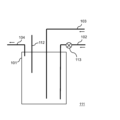
- FIG. 1 is a schematic diagram showing an example of a hydrogen sulfide production apparatus according to the present invention.
- FIG. 1 is a schematic diagram showing an example of a hydrogen sulfide production apparatus according to the present invention.
- FIG. 1 is a schematic diagram showing an example of a hydrogen sulfide production apparatus according to the present invention.
- FIG. 1 is a schematic diagram showing an example of a hydrogen sulfide production apparatus according to the present invention.
- FIG. 2 is a schematic diagram showing an example of a tip portion of a sulfur amount detection unit.
- FIG. 1 is a schematic diagram showing an example of a hydrogen sulfide production apparatus according to the present invention.
- FIG. 1 is a schematic diagram showing an example of a hydrogen sulfide production apparatus according to the present invention.
- FIG. 1 is a schematic diagram showing an example of a hydrogen sulfide production apparatus according to the present invention.
- FIG. 1 is a schematic diagram showing an example of a hydrogen sulfide production apparatus according to the present invention.
- FIG. 1 is a schematic diagram showing an example of a hydrogen sulfide production apparatus according to the present invention.
- FIG. 1 is a schematic diagram showing an example of a hydrogen sulfide production apparatus according to the present invention.
- the hydrogen sulfide production method is a hydrogen sulfide production method in which sulfur gas and hydrogen gas are reacted in a reaction tank to synthesize hydrogen sulfide, and includes the steps of: supplying a mixed gas of sulfur gas and hydrogen gas to the reaction tank; supplying hydrogen gas to the reaction tank; and reacting sulfur gas with hydrogen gas to synthesize hydrogen sulfide.
- the amount of sulfur in the reaction tank is detected, and the amount of hydrogen gas supplied in the step (B) is adjusted based on the result of the detection.
- the sulfur will liquefy or solidify at the location where the excess sulfur state occurs, inhibiting the reaction between sulfur gas and hydrogen gas and reducing the efficiency of hydrogen sulfide production.
- the occurrence of a localized excess sulfur state in the reaction tank can be suppressed, thereby improving reaction efficiency.
- the hydrogen sulfide production method is a method for producing hydrogen sulfide in which sulfur gas and hydrogen gas are reacted in a reaction tank 101 to synthesize hydrogen sulfide, and includes a step (A) of supplying a mixed gas of sulfur gas and hydrogen gas to the reaction tank 101, a step (B) of supplying hydrogen gas to the reaction tank 101, and a step (C) of reacting the sulfur gas with the hydrogen gas to synthesize hydrogen sulfide.
- the amount of sulfur in the reaction tank 101 is detected, and the amount of hydrogen gas supplied in the step (B) is adjusted based on the result.
- step (A) for example, a mixed gas of hydrogen gas and sulfur gas is supplied to the reaction vessel 101 by the mixed gas supply unit 102.
- the mixed gas supply unit may be, for example, a pipe.
- step (B) hydrogen gas is supplied to the reaction vessel 101 by, for example, the hydrogen gas supply unit 103.
- the hydrogen gas supply unit may be, for example, a pipe.
- step (C) the mixed gas and hydrogen gas supplied to the reaction tank 101 react in the reaction tank 101 to synthesize hydrogen sulfide. It is believed that the reaction represented by the following formula (1) occurs in the reaction tank 101. H2 +S ⁇ H2S (1)
- the generated hydrogen sulfide-containing gas is recovered from the reaction tank 101, for example, by the hydrogen sulfide-containing gas recovery unit 104.
- the hydrogen sulfide-containing gas recovery unit may be, for example, a pipe.
- the reaction tank 101, the mixed gas supply unit 102, the hydrogen gas supply unit 103, and the hydrogen sulfide-containing gas recovery unit 104 each contain, for example, one or more materials selected from the group consisting of carbon, stainless steel, glass, alumina, aluminum, Inconel (registered trademark), and Hastelloy (registered trademark). From the viewpoint of strength and preventing the inclusion of metal impurities, the reaction tank 101 preferably contains one or more materials selected from stainless steel and glass, more preferably contains glass, and even more preferably contains quartz glass.
- the reaction tank 101 may be provided with an agitation function.
- an agitation function such as that of a rotary kiln may be used.
- step (B) if the amount of sulfur in the reaction tank 101 is excessive, it is preferable to increase the amount of hydrogen gas supplied in step (B). This promotes the reaction between the excess sulfur and hydrogen gas, and makes it possible to further suppress the occurrence of a localized excess sulfur state in the reaction tank.
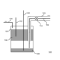
- a porous material 106 is preferably installed in the reaction tank 101. This promotes the reaction between sulfur gas and hydrogen gas on the surface of the porous material 106, further accelerating the synthesis of hydrogen sulfide.
- the porous material 106 contains one or more materials selected from the group consisting of activated carbon, zeolite, and activated alumina, and more preferably contains activated alumina, in order to promote the hydrogen sulfide production reaction.
- the temperature at which hydrogen sulfide is produced i.e., the temperature in step (C), is preferably 300°C or higher, more preferably 330°C or higher, and even more preferably 360°C or higher, from the viewpoint of promoting the production of hydrogen sulfide, and is preferably 500°C or lower, more preferably 480°C or lower, and even more preferably 450°C or lower, from the viewpoint of suppressing side reactions and deterioration of the catalyst.
- FIG. 3 is a schematic diagram showing a hydrogen sulfide production device that is an example of the hydrogen sulfide production device 107 according to the present invention.
- the method for producing hydrogen sulfide according to this embodiment preferably further includes a step of heating sulfur 109 in the molten sulfur tank 108 to generate sulfur gas. This makes it easier to control the supply amount of sulfur gas.
- the hydrogen sulfide production apparatus it is preferable to maintain the internal pressure in the reaction tank constant by adjusting the amount of mixed gas supplied and the amount of hydrogen gas supplied. This makes it possible to suppress changes in reaction conditions due to changes in the internal pressure in the reaction tank 101.
- the temperature of the molten sulfur tank 108 is not particularly limited as long as it is a temperature at which sulfur vapor is generated, and is, for example, 180°C or higher, preferably 220°C or higher, more preferably 260°C or higher, even more preferably 280°C or higher, and even more preferably 300°C or higher, and from the viewpoint of suppressing the production of rubber-like sulfur, is, for example, 440°C or lower, preferably 400°C or lower, more preferably 360°C or lower, even more preferably 340°C or lower, and even more preferably 320°C or lower.
- the mixed gas supply unit 102 it is preferable to make the mixed gas supply unit 102 movable in the vertical direction, for example. This makes it possible to adjust the position of the end of the mixed gas supply unit 102 in accordance with any fluctuations in the liquid level of the sulfur 109. This allows the sulfur gas to be lifted up even more efficiently.
Landscapes
- Chemical & Material Sciences (AREA)
- Organic Chemistry (AREA)
- Engineering & Computer Science (AREA)
- Physics & Mathematics (AREA)
- Health & Medical Sciences (AREA)
- Life Sciences & Earth Sciences (AREA)
- Chemical Kinetics & Catalysis (AREA)
- General Health & Medical Sciences (AREA)
- Analytical Chemistry (AREA)
- Biochemistry (AREA)
- General Physics & Mathematics (AREA)
- Immunology (AREA)
- Pathology (AREA)
- Inorganic Chemistry (AREA)
- Spectroscopy & Molecular Physics (AREA)
- Materials Engineering (AREA)
- Medicinal Chemistry (AREA)
- Food Science & Technology (AREA)
- Combustion & Propulsion (AREA)
- Catalysts (AREA)
Priority Applications (4)
| Application Number | Priority Date | Filing Date | Title |
|---|---|---|---|
| EP23914823.2A EP4647397A1 (en) | 2023-01-06 | 2023-12-28 | Method for producing hydrogen sulfide and hydrogen sulfide production device |
| KR1020257022926A KR20250121387A (ko) | 2023-01-06 | 2023-12-28 | 황화수소의 제조방법 및 황화수소 제조장치 |
| CN202380090318.0A CN120530078A (zh) | 2023-01-06 | 2023-12-28 | 硫化氢的制造方法和硫化氢制造装置 |
| JP2024568924A JP7842902B2 (ja) | 2023-01-06 | 2023-12-28 | 硫化水素の製造方法および硫化水素製造装置 |
Applications Claiming Priority (2)
| Application Number | Priority Date | Filing Date | Title |
|---|---|---|---|
| JP2023001324 | 2023-01-06 | ||
| JP2023-001324 | 2023-01-06 |
Publications (1)
| Publication Number | Publication Date |
|---|---|
| WO2024147338A1 true WO2024147338A1 (ja) | 2024-07-11 |
Family
ID=91804032
Family Applications (1)
| Application Number | Title | Priority Date | Filing Date |
|---|---|---|---|
| PCT/JP2023/047269 Ceased WO2024147338A1 (ja) | 2023-01-06 | 2023-12-28 | 硫化水素の製造方法および硫化水素製造装置 |
Country Status (5)
| Country | Link |
|---|---|
| EP (1) | EP4647397A1 (https=) |
| JP (1) | JP7842902B2 (https=) |
| KR (1) | KR20250121387A (https=) |
| CN (1) | CN120530078A (https=) |
| WO (1) | WO2024147338A1 (https=) |
Citations (5)
| Publication number | Priority date | Publication date | Assignee | Title |
|---|---|---|---|---|
| JPH01257109A (ja) * | 1988-04-07 | 1989-10-13 | Jgc Corp | 硫化水素の製造方法 |
| JPH03103311A (ja) * | 1989-09-14 | 1991-04-30 | Jgc Corp | 硫化水素の製造方法およびその製造装置 |
| JP2003321212A (ja) | 2002-04-26 | 2003-11-11 | Sumitomo Seika Chem Co Ltd | 硫化水素の製造方法 |
| JP2022184226A (ja) * | 2021-05-31 | 2022-12-13 | 古河機械金属株式会社 | 硫化水素製造装置および硫化水素の製造方法 |
| JP2023001324A (ja) | 2017-05-26 | 2023-01-04 | Line株式会社 | 映像コーディングを行うコンピュータプログラム |
Family Cites Families (4)
| Publication number | Priority date | Publication date | Assignee | Title |
|---|---|---|---|---|
| JPS59116104A (ja) * | 1982-12-22 | 1984-07-04 | Riken Keiki Kk | 硫化水素発生器 |
| JP5700160B2 (ja) | 2014-05-13 | 2015-04-15 | 住友金属鉱山株式会社 | 硫化水素ガス製造プラント及び硫化水素ガスの排気方法 |
| CN112368238A (zh) | 2018-07-12 | 2021-02-12 | 国立研究开发法人物质·材料研究机构 | 含有硫化氢缓释剂的包装体及其制造方法和硫化氢缓释剂、硫化氢缓释体以及使用了它们的硫化氢的产生方法 |
| JP7226181B2 (ja) * | 2019-08-08 | 2023-02-21 | 住友金属鉱山株式会社 | 硫化水素ガスの除害設備 |
-
2023
- 2023-12-28 EP EP23914823.2A patent/EP4647397A1/en active Pending
- 2023-12-28 WO PCT/JP2023/047269 patent/WO2024147338A1/ja not_active Ceased
- 2023-12-28 KR KR1020257022926A patent/KR20250121387A/ko active Pending
- 2023-12-28 JP JP2024568924A patent/JP7842902B2/ja active Active
- 2023-12-28 CN CN202380090318.0A patent/CN120530078A/zh active Pending
Patent Citations (5)
| Publication number | Priority date | Publication date | Assignee | Title |
|---|---|---|---|---|
| JPH01257109A (ja) * | 1988-04-07 | 1989-10-13 | Jgc Corp | 硫化水素の製造方法 |
| JPH03103311A (ja) * | 1989-09-14 | 1991-04-30 | Jgc Corp | 硫化水素の製造方法およびその製造装置 |
| JP2003321212A (ja) | 2002-04-26 | 2003-11-11 | Sumitomo Seika Chem Co Ltd | 硫化水素の製造方法 |
| JP2023001324A (ja) | 2017-05-26 | 2023-01-04 | Line株式会社 | 映像コーディングを行うコンピュータプログラム |
| JP2022184226A (ja) * | 2021-05-31 | 2022-12-13 | 古河機械金属株式会社 | 硫化水素製造装置および硫化水素の製造方法 |
Non-Patent Citations (1)
| Title |
|---|
| See also references of EP4647397A1 |
Also Published As
| Publication number | Publication date |
|---|---|
| CN120530078A (zh) | 2025-08-22 |
| EP4647397A1 (en) | 2025-11-12 |
| JPWO2024147338A1 (https=) | 2024-07-11 |
| KR20250121387A (ko) | 2025-08-12 |
| JP7842902B2 (ja) | 2026-04-08 |
Similar Documents
| Publication | Publication Date | Title |
|---|---|---|
| US7744728B2 (en) | Apparatus for and method of producing hydrogen using microwaves | |
| EP2106385B1 (en) | Method for producing a hydrogen enriched fuel using microwave assisted methane plasma decomposition on catalyst | |
| Barbarossa et al. | Catalytic thermal decomposition of sulphuric acid in sulphur–iodine cycle for hydrogen production | |
| JP6508673B2 (ja) | 硫化リチウムの製造方法 | |
| JP2010516610A (ja) | 触媒に対してマイクロ波誘起メタン分解を使用する水素富化燃料を生成するための方法及びシステム | |
| US20240316519A1 (en) | Ammonia decomposition system | |
| Bishara et al. | Thermochemical decomposition of hydrogen sulfide by solar energy | |
| Chuayboon et al. | Clean magnesium production using concentrated solar heat in a high-temperature cavity-type thermochemical reactor | |
| Puig et al. | Production of metallic nanopowders (Mg, Al) by solar carbothermal reduction of their oxides at low pressure | |
| WO2024147338A1 (ja) | 硫化水素の製造方法および硫化水素製造装置 | |
| CN115072670B (zh) | 一种熔融盐分解硫化氢制取单质硫和氢气的反应装置 | |
| Bento et al. | Surface properties enhancement by sulfur-doping TiO2 films | |
| RU2236894C2 (ru) | Способ извлечения сернистых соединений из газа | |
| Wang et al. | Reactivity and stability of different pyrites as sulfur carriers for chemical looping decomposition of H2S into H2 and S | |
| AU2005201340B2 (en) | Process for producing synthesis gas for the Fischer-Tropsch synthesis and producing apparatus thereof | |
| EP4192784A1 (en) | Melt pyrolysis of hydrocarbon feedstock containing nitrogen and/or hydrogen sulphide | |
| JP2026053724A (ja) | 硫化リチウムの製造装置 | |
| JP2023501945A (ja) | 炭素酸化物から製造されたコークスの熱処理 | |
| EP4480907A1 (en) | Method and device for recovering carbon from carbon-containing gas | |
| CA2380117A1 (en) | Process for producing syngas in a short contact time reactor using catalytic partial oxidation of hydrogen sulfide | |
| US12415159B2 (en) | Nuclear driven carbon dioxide sequestration system and method | |
| RU2825660C1 (ru) | Способ получения порошка карбида металла шестой группы | |
| CN107720805B (zh) | 一种金属锌非平衡氧化法制备纳米氧化锌的装置 | |
| US20250297178A1 (en) | Method for producing synthesis gas and fuel production system | |
| US20250171301A1 (en) | Device and method for the pyrolysis of hydrogen-containing compounds |
Legal Events
| Date | Code | Title | Description |
|---|---|---|---|
| 121 | Ep: the epo has been informed by wipo that ep was designated in this application |
Ref document number: 23914823 Country of ref document: EP Kind code of ref document: A1 |
|
| WWE | Wipo information: entry into national phase |
Ref document number: 2024568924 Country of ref document: JP |
|
| WWE | Wipo information: entry into national phase |
Ref document number: 202380090318.0 Country of ref document: CN |
|
| ENP | Entry into the national phase |
Ref document number: 1020257022926 Country of ref document: KR Free format text: ST27 STATUS EVENT CODE: A-0-1-A10-A15-NAP-PA0105 (AS PROVIDED BY THE NATIONAL OFFICE) |
|
| WWE | Wipo information: entry into national phase |
Ref document number: 1020257022926 Country of ref document: KR |
|
| WWE | Wipo information: entry into national phase |
Ref document number: 2023914823 Country of ref document: EP |
|
| NENP | Non-entry into the national phase |
Ref country code: DE |
|
| ENP | Entry into the national phase |
Ref document number: 2023914823 Country of ref document: EP Effective date: 20250806 |
|
| WWP | Wipo information: published in national office |
Ref document number: 1020257022926 Country of ref document: KR |
|
| WWP | Wipo information: published in national office |
Ref document number: 202380090318.0 Country of ref document: CN |
|
| WWP | Wipo information: published in national office |
Ref document number: 2023914823 Country of ref document: EP |