WO2024147242A1 - 切削工具及び切削加工物の製造方法 - Google Patents
切削工具及び切削加工物の製造方法 Download PDFInfo
- Publication number
- WO2024147242A1 WO2024147242A1 PCT/JP2023/042455 JP2023042455W WO2024147242A1 WO 2024147242 A1 WO2024147242 A1 WO 2024147242A1 JP 2023042455 W JP2023042455 W JP 2023042455W WO 2024147242 A1 WO2024147242 A1 WO 2024147242A1
- Authority
- WO
- WIPO (PCT)
- Prior art keywords
- recess
- insert
- cutting tool
- seat
- hole
- Prior art date
- Legal status (The legal status is an assumption and is not a legal conclusion. Google has not performed a legal analysis and makes no representation as to the accuracy of the status listed.)
- Ceased
Links
Images









Classifications
-
- B—PERFORMING OPERATIONS; TRANSPORTING
- B23—MACHINE TOOLS; METAL-WORKING NOT OTHERWISE PROVIDED FOR
- B23B—TURNING; BORING
- B23B29/00—Holders for non-rotary cutting tools; Boring bars or boring heads; Accessories for tool holders
- B23B29/04—Tool holders for a single cutting tool
- B23B29/043—Tool holders for a single cutting tool with cutting-off, grooving or profile cutting tools, i.e. blade- or disc-like main cutting parts
-
- B—PERFORMING OPERATIONS; TRANSPORTING
- B23—MACHINE TOOLS; METAL-WORKING NOT OTHERWISE PROVIDED FOR
- B23B—TURNING; BORING
- B23B27/00—Tools for turning or boring machines; Tools of a similar kind in general; Accessories therefor
- B23B27/14—Cutting tools of which the bits or tips or cutting inserts are of special material
-
- B—PERFORMING OPERATIONS; TRANSPORTING
- B23—MACHINE TOOLS; METAL-WORKING NOT OTHERWISE PROVIDED FOR
- B23B—TURNING; BORING
- B23B27/00—Tools for turning or boring machines; Tools of a similar kind in general; Accessories therefor
- B23B27/14—Cutting tools of which the bits or tips or cutting inserts are of special material
- B23B27/16—Cutting tools of which the bits or tips or cutting inserts are of special material with exchangeable cutting bits or cutting inserts, e.g. able to be clamped
-
- B—PERFORMING OPERATIONS; TRANSPORTING
- B23—MACHINE TOOLS; METAL-WORKING NOT OTHERWISE PROVIDED FOR
- B23B—TURNING; BORING
- B23B27/00—Tools for turning or boring machines; Tools of a similar kind in general; Accessories therefor
- B23B27/14—Cutting tools of which the bits or tips or cutting inserts are of special material
- B23B27/16—Cutting tools of which the bits or tips or cutting inserts are of special material with exchangeable cutting bits or cutting inserts, e.g. able to be clamped
- B23B27/1614—Cutting tools of which the bits or tips or cutting inserts are of special material with exchangeable cutting bits or cutting inserts, e.g. able to be clamped with plate-like cutting inserts of special shape clamped against the walls of the recess in the shank by a clamping member acting upon the wall of a hole in the insert
-
- B—PERFORMING OPERATIONS; TRANSPORTING
- B23—MACHINE TOOLS; METAL-WORKING NOT OTHERWISE PROVIDED FOR
- B23B—TURNING; BORING
- B23B27/00—Tools for turning or boring machines; Tools of a similar kind in general; Accessories therefor
- B23B27/14—Cutting tools of which the bits or tips or cutting inserts are of special material
- B23B27/16—Cutting tools of which the bits or tips or cutting inserts are of special material with exchangeable cutting bits or cutting inserts, e.g. able to be clamped
- B23B27/1614—Cutting tools of which the bits or tips or cutting inserts are of special material with exchangeable cutting bits or cutting inserts, e.g. able to be clamped with plate-like cutting inserts of special shape clamped against the walls of the recess in the shank by a clamping member acting upon the wall of a hole in the insert
- B23B27/1622—Cutting tools of which the bits or tips or cutting inserts are of special material with exchangeable cutting bits or cutting inserts, e.g. able to be clamped with plate-like cutting inserts of special shape clamped against the walls of the recess in the shank by a clamping member acting upon the wall of a hole in the insert characterised by having a special shape
-
- B—PERFORMING OPERATIONS; TRANSPORTING
- B23—MACHINE TOOLS; METAL-WORKING NOT OTHERWISE PROVIDED FOR
- B23B—TURNING; BORING
- B23B27/00—Tools for turning or boring machines; Tools of a similar kind in general; Accessories therefor
- B23B27/14—Cutting tools of which the bits or tips or cutting inserts are of special material
- B23B27/16—Cutting tools of which the bits or tips or cutting inserts are of special material with exchangeable cutting bits or cutting inserts, e.g. able to be clamped
- B23B27/1666—Cutting tools of which the bits or tips or cutting inserts are of special material with exchangeable cutting bits or cutting inserts, e.g. able to be clamped with plate-like cutting inserts clamped by a clamping member acting almost perpendicularly on chip-forming plane
-
- B—PERFORMING OPERATIONS; TRANSPORTING
- B23—MACHINE TOOLS; METAL-WORKING NOT OTHERWISE PROVIDED FOR
- B23C—MILLING
- B23C2210/00—Details of milling cutters
- B23C2210/16—Fixation of inserts or cutting bits in the tool
- B23C2210/168—Seats for cutting inserts, supports for replacable cutting bits
Definitions
- This disclosure relates to a method for manufacturing cutting tools and machined products.
- Cutting tools used in cutting workpieces include those described in Patent Documents 1 to 3, for example. All of the cutting tools described in Patent Documents 1 to 3 include an insert, a holder, and a clamper. When the cutting tool includes a clamper, the insert can be pulled toward the restraining surface of the holder by the clamper, improving the positioning accuracy of the insert.
- a cutting tool is a cutting tool extending from a tip end to a rear end along a reference axis, and includes a holder having a pocket located on the tip end side, an insert attached to the pocket, and a plurality of fasteners for fixing the insert to the pocket.
- the insert has a first surface, a second surface located opposite the first surface, a through hole opening in the first surface and the second surface, and a first recess located in the first surface.
- the plurality of fasteners includes a first fastener inserted into the through hole, and a second fastener engaged with the first recess.
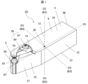
- FIG. 1 is a perspective view showing a cutting tool according to a first embodiment.
- FIG. FIG. 1 is an exploded perspective view showing a cutting tool according to a first embodiment.
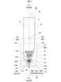
- FIG. 2 is a plan view of the cutting tool shown in the first embodiment, seen from the front, i.e., from above, from a first surface side.
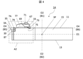
- FIG. 2 is a plan view of the cutting tool shown in the first embodiment as viewed from the right side.
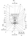
- FIG. 4 is an enlarged view corresponding to an area A1 shown in FIG. 3.
- 6 is an enlarged view of the VI-VI cross section shown in FIG. 5, which corresponds to the region A2 shown in FIG.
- FIG. 11 is a perspective view showing a cutting tool according to a second embodiment.
- FIG. 11 is a plan view of the cutting tool shown in the second embodiment, seen from the front, i.e., from above, from the first surface side.
- FIG. 9 is an enlarged view corresponding to an area A3 shown in FIG. 8 .
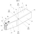
- FIG. 11 is a perspective view showing a cutting tool according to a third embodiment.
- FIG. 11 is an exploded perspective view showing a cutting tool according to a third embodiment.
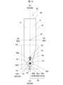
- FIG. 11 is a plan view of the cutting tool shown in the third embodiment, seen from the first surface side, i.e., seen from above.
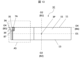
- FIG. 11 is a plan view of the cutting tool shown in the third embodiment, as viewed from the right side.
- FIG. 13 is an enlarged view corresponding to an area A4 shown in FIG. 12.
- FIG. 15 is an enlarged view of the XV-XV cross section shown in FIG. 14, corresponding to region A5 shown in FIG. 13.
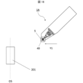
- FIG. 2 is a schematic explanatory diagram showing one step of a method for producing a machined product according to one embodiment.
- FIG. 2 is a schematic explanatory diagram showing one step of a method for producing a machined product according to one embodiment.
- FIG. 2 is a schematic explanatory diagram showing one step of a method for producing a machined product according to one embodiment.
- the shape of the cutting tool 1A on the side of the first end 3A is a square prism shape.
- the square prism shape does not necessarily mean a strict square prism shape, and may have a hole or a groove in a part of it, for example.
- the holder 3 may have a main body 9.
- the main body 9 shown in the first embodiment may have a shape extending from the first end 3A to the second end 3B along the reference axis O1, as shown in FIG. 1 etc.
- the main body 9 shown in the first embodiment has a columnar shape, more specifically, a rectangular columnar shape.
- the shape of the main body 9 is not limited to a rectangular columnar shape, and may be, for example, a cylindrical shape.
- the main body 9 may have an upper surface 11, a lower surface 13, and side surfaces 15.
- the main body 9 shown in the first embodiment has an upper surface 11, a lower surface 13, and multiple side surfaces 15.
- the lower surface 13 is the surface located opposite the upper surface 11, and the side surfaces 15 are the surfaces located between the upper surface 11 and the lower surface 13.
- the example shank 19 shown in FIG. 1 etc. has a rectangular prism shape.
- the central axis of the shank 19 may be regarded as the reference axis O1 of the cutting tool 1A.
- the central axis of the shank 19 that passes through the center of the rear end face of the shank 19 and extends in a direction parallel to the four side faces of the shank 19 can be regarded as the reference axis O1.
- the holder 3 may have a pocket 21 located on the side of the first end 3A.
- the pocket 21 may be located in the head 17.
- the pocket 21 is a recessed portion where the insert 5 is attached.
- the pocket 21 may have a seat 23.
- the seat 23 is a surface facing in the same direction as the upper surface 11.
- the pocket 21 may have a restraining surface 25.
- the restraining surface 25 may be connected to the seat 23, or a groove may be provided between the seat 23 and the restraining surface 25, as in the example shown in FIG. 2.
- the seat 23 and the restraining surface 25 are surfaces against which the insert 5 abuts. Note that, if the holder 3 has a sheet member 87 described below, the upper surface (first sheet surface 89) of the sheet member 87 functions as the seat 23. Also, if the holder 3 does not have a sheet member 87, the seat 23 is located in the main body 9.
- the pocket 21 shown in the first embodiment has two restraining surfaces 25 facing the first end 3A.
- the two restraining surfaces 25 may be connected to each other, or a groove may be provided between these restraining surfaces 25, as in the example shown in FIG. 2. There is no particular limit to the number of restraining surfaces 25.
- the holder 3 (main body 9) may have a first insertion opening 27 and a second insertion opening 29.
- the first insertion opening 27 and the second insertion opening 29 are both portions into which the fixing device 7 is inserted.
- the first insertion opening 27 may be connected to a first opening 31 located in the seat surface 23.
- the first insertion opening 27 extends from the first opening 31 toward the lower surface 13.
- the first insertion opening 27 may extend in a direction perpendicular to the reference axis O1 in a cross section perpendicular to the seat surface 23.
- the second insertion opening 29 may be connected to a second opening 33 located on the top surface 11. As shown in FIG. 2, the second opening 33 may be located closer to the second end 3B than the first opening 31. In the holder 3 shown in the first embodiment, the second insertion opening 29 extends from the second opening 33 toward the bottom surface 13. The second insertion opening 29 may extend in a direction perpendicular to the reference axis O1 in a cross section perpendicular to the top surface 11.
- the insert 5 may have a first surface 35, a second surface 37, and a third surface 39.
- the second surface 37 may be a surface located opposite the first surface 35
- the third surface 39 may be a surface located between the first surface 35 and the second surface 37.
- the insert 5 shown in the first embodiment has a first surface 35, a second surface 37, and multiple third surfaces 39.
- the insert 5 may have a through hole 51 and a recess 57, which will be described later.
- the recess 57 is located on the first surface 35. As shown in FIG. 2, in this embodiment, the recess 57 is located on the upper surface of the insert 5, so the "upper surface" of the insert 5 corresponds to the first surface 35.
- the lower surface of the insert 5 corresponds to the second surface 37, which is located on the opposite side to the first surface 35.
- the first surface 35 may have a scooping surface region 41
- the third surface 39 may have a clearance surface region 43.
- the shapes of the first surface 35, the second surface 37, and the third surface 39 may be, for example, rectangular.
- any one side may be the right side and the other side may be the left side.
- the B1 direction is the upper side
- the B2 direction is the lower side
- the B3 direction is the right side
- the B4 direction is the left side.
- the straight line perpendicular to the first surface 35 and the up-down axis O2 are parallel, and the upper side is synonymous with the side of the first surface 35, and the lower side is synonymous with the side of the second surface 37.
- the engagement portion 79 may have a recess 81 that is concave toward the front end.
- the recess 81 may be concave toward the first end 3A.
- the lower end of the recess 81 may contact the second peripheral wall portion 59B.
- the bottom 83 of the recess 81 may be located forward of at least a portion of the first recess 57A or toward the first end 3A.
- the bottom 83 of the recess 81 may be a dot area as shown in FIG. 6. It may be located above the recess 57.
- the bottom 83 of the recess 81 may be located above the recess 57.
- the first seat surface 89 abuts against the lower surface (second surface 37) of the insert 5.
- the first seat surface 89 faces upward, the same as the upper surface (first surface 35) of the insert 5.
- the second seat surface 91 may be located on the opposite side of the first seat surface 89.
- the second seat surface 91 may also abut against the main body portion 9.
- the second seat surface 91 may face downward, the same as the lower surface (second surface 37) of the insert 5.
- the pocket 21 may be formed by the main body portion 9 and the seat member 87.
- the recess 57 located on the first surface 35 and the recess 57 located on the second surface 37 may be positioned point symmetrically with respect to the center 5P of the insert 5. In such a case, when the insert 5 is attached to the main body 9 with the first surface 35 and the second surface 37 reversed, the position of the insert 5 can be determined without changing the position of the second fastener 7B, etc.
- the screw may be made of, for example, SCM440.
- the clamp 69 may be made of, for example, SCM440.
- the sheet member 87 may be made of, for example, cemented carbide.
- the retraction member 99 has a lower front portion (first portion 105) that contacts the main body 9, while a rear portion (second portion 107) is spaced apart from the main body 9. Therefore, when a force is applied downward from the first abutment surface 101 to the second abutment surface 103 at a location farther away from the center 5P of the insert 5 than the first portion 105, the retraction member 99 rotates clockwise with the first portion 105 as a fulcrum in the cross section shown in FIG. 15. As a result, the retraction member 99 can apply a force in the recess 57 in a direction that moves the insert 5 rearward, thereby enabling the insert 5 to be positioned.
- the seat member 87 may have a seat hole 109 penetrating the first seat surface 89 and the second seat surface 91. As shown in FIG. 15, the seat hole 109 is aligned with the recess 57 in the direction in which the vertical axis O2 extends.
- the second fixing device 7B has a retraction member 99 that passes through the seat hole 109 and engages with the recess 57.
- the workpiece 201 is rotated around the rotation axis O5, and the cutting tool 1A is brought relatively close to the workpiece 201.
- the cutting edge 49 of the cutting tool 1A is brought into contact with the rotating workpiece 201 to cut the workpiece 201.
- the cutting tool 1A is moved relatively away from the workpiece 201.
- the cutting tool 1A is moved in the Y1 direction while the workpiece 201 is rotated around the rotation axis O5, thereby approaching the workpiece 201. Also, in FIG. 17, the cutting edge 49 of the insert 5 is brought into contact with the rotating workpiece 201 to cut the workpiece 201. Also, in FIG. 18, the cutting tool 1A is moved away from the workpiece 201 by moving it in the Y2 direction while the workpiece 201 is rotated.
- step (C1) the workpiece 201 may be brought closer to the cutting tool 1A.
- step (C3) the workpiece 201 may be moved away from the cutting tool 1A.
- the workpiece 201 may be kept rotating and the process of contacting the cutting edge 49 of the insert 5 with different locations on the workpiece 201 may be repeated.
- examples of the material of the workpiece 201 include carbon steel, alloy steel, stainless steel, cast iron, and non-ferrous metals.
- the first surface may have a corner located on the rear end side, and when the first surface is viewed from the front, the first recess may be located on an imaginary line segment connecting the center axis of the through hole and the midpoint of the corner.
- the first fixture when the first surface is viewed from the front, the first fixture may be located away from the second fixture.
- the first recess has a bottom and a peripheral wall connected to the bottom, and the second fixture is in contact with the peripheral wall and spaced from the bottom.
- the second fixture has an engagement portion that overlaps with the first surface when viewed from above, the engagement portion having a recess that is concave toward the tip, and the bottom of the recess may be located closer to the tip than at least a portion of the first recess.
- the insert may further have a second recess located on the first surface
- the second fixture may have a first arm portion and a second arm portion, the first arm portion may engage with the first recess, and the second arm portion may engage with the second recess.
- the through hole when the first surface is viewed from the front, the through hole may be located between the first recess and the second recess.
- the through hole may be located on a virtual straight line passing through the first recess and the second recess.
- the pocket may have a seat surface, the first surface may abut against the seat surface, the holder may have a main body portion and a seat member located on the seat surface, the seat member may have a first seat surface that abuts against the second surface, a second seat surface that is located on the opposite side of the first seat surface and abuts against the main body portion, and a seat hole that penetrates the first seat surface and the second seat surface, and the second fixing device may have an arm portion that passes through the seat hole and engages with the first recess.
- the method may include a step of rotating a workpiece, a step of bringing any one of the cutting tools (1) to (10) into contact with the rotating workpiece, and a step of removing the cutting tool from the workpiece.
- the insert 5 can be positioned by engaging the arm portion 77 of the second fastener 7B with the recess 57 of the insert 5, but there are no particular limitations on the shape of these engaging portions.
- the insert 5 may have a convex portion
- the second fastener 7B may have a portion with a shape (such as a concave shape) that can engage with the convex portion
- the insert may be positioned by engaging the convex portion of the insert with the corresponding portion of the second fastener.
- Cutting tool 3 Main body 3A: First end (tip) 3B: Second end (rear end) 3P: Center of main body 5: Cutting insert 5P...Center of cutting insert (insert) 7...Fixed tool 7A...First fixed tool 7B...Second fixed tool 7BP...Center of second fixed tool 9...Main body 11...Upper surface 13...Lower surface 15...Side surface 17...Head 19...Shank 21...Pocket 23...Seat surface 25...Restraint surface 27...First insertion opening 29...Second insertion opening 31...First opening 33...Second opening 35...First surface 35P...Center of first surface 37...Second surface 37P...Center of second surface 39...Third surface 41...Rake face area 43...Flank face area 45...
- Corner 45A First corner 45AP...Midpoint of first corner 45B...Second corner 45BP...Midpoint of second corner 45C...Third corner 45CP...Midpoint of third corner 45D...Fourth corner 45DP...Midpoint of fourth corner 45CP...Side 47A...First side 47B...Second side 49...Cutting edge 49A...First cutting edge 49B...Second cutting edge 49Z...Corner cutting edge 51...Through hole 51P...Center of through hole 53...First opening 55...Second opening 57...Recess 57A...First recess 57AP...Center of first recess 57B...Second recess 57BP... Center 59 of second recess 59A...
Landscapes
- Engineering & Computer Science (AREA)
- Mechanical Engineering (AREA)
- Cutting Tools, Boring Holders, And Turrets (AREA)
Priority Applications (4)
| Application Number | Priority Date | Filing Date | Title |
|---|---|---|---|
| JP2024568704A JPWO2024147242A1 (https=) | 2023-01-06 | 2023-11-28 | |
| CN202380088223.5A CN120344336A (zh) | 2023-01-06 | 2023-11-28 | 切削刀具以及切削加工物的制造方法 |
| DE112023005529.7T DE112023005529T5 (de) | 2023-01-06 | 2023-11-28 | Schneidwerkzeug und verfahren zur herstellung eines maschinell bearbeiteten produkts |
| KR1020257020869A KR20250112853A (ko) | 2023-01-06 | 2023-11-28 | 절삭 공구 및 절삭 가공물의 제조 방법 |
Applications Claiming Priority (2)
| Application Number | Priority Date | Filing Date | Title |
|---|---|---|---|
| JP2023-001143 | 2023-01-06 | ||
| JP2023001143 | 2023-01-06 |
Publications (1)
| Publication Number | Publication Date |
|---|---|
| WO2024147242A1 true WO2024147242A1 (ja) | 2024-07-11 |
Family
ID=91803785
Family Applications (1)
| Application Number | Title | Priority Date | Filing Date |
|---|---|---|---|
| PCT/JP2023/042455 Ceased WO2024147242A1 (ja) | 2023-01-06 | 2023-11-28 | 切削工具及び切削加工物の製造方法 |
Country Status (5)
| Country | Link |
|---|---|
| JP (1) | JPWO2024147242A1 (https=) |
| KR (1) | KR20250112853A (https=) |
| CN (1) | CN120344336A (https=) |
| DE (1) | DE112023005529T5 (https=) |
| WO (1) | WO2024147242A1 (https=) |
Cited By (1)
| Publication number | Priority date | Publication date | Assignee | Title |
|---|---|---|---|---|
| WO2026018875A1 (ja) * | 2024-07-18 | 2026-01-22 | 京セラ株式会社 | 被覆工具、切削工具、および切削加工物の製造方法 |
Citations (8)
| Publication number | Priority date | Publication date | Assignee | Title |
|---|---|---|---|---|
| JPS526184A (en) * | 1975-06-30 | 1977-01-18 | Gen Electric | Cutting tools |
| JPS54174083U (https=) * | 1978-05-29 | 1979-12-08 | ||
| JPS6097205U (ja) * | 1983-12-09 | 1985-07-02 | 日本特殊陶業株式会社 | バイトホルダ |
| JPH0631904U (ja) * | 1992-09-28 | 1994-04-26 | 三菱マテリアル株式会社 | スローアウェイ式切削工具 |
| JPH0866804A (ja) * | 1994-08-25 | 1996-03-12 | Barta Ag | 形状接続により確保された切削チップ |
| JP2009066746A (ja) * | 2006-11-22 | 2009-04-02 | Mitsubishi Materials Corp | 切削インサート |
| JP2011115923A (ja) * | 2009-12-07 | 2011-06-16 | Ryokosha:Kk | 工具ホルダ |
| JP2017074672A (ja) * | 2013-04-27 | 2017-04-20 | 京セラ株式会社 | 転削工具用切削インサート、転削工具および切削加工物の製造方法 |
Family Cites Families (2)
| Publication number | Priority date | Publication date | Assignee | Title |
|---|---|---|---|---|
| KR20090095918A (ko) | 2008-03-06 | 2009-09-10 | 삼성디지털이미징 주식회사 | 플래시 장치 및 이를 구비한 촬상 장치 |
| ES2810006T3 (es) | 2017-03-22 | 2021-03-08 | Ceram Gmbh | Sistema de herramienta |
-
2023
- 2023-11-28 KR KR1020257020869A patent/KR20250112853A/ko active Pending
- 2023-11-28 JP JP2024568704A patent/JPWO2024147242A1/ja active Pending
- 2023-11-28 WO PCT/JP2023/042455 patent/WO2024147242A1/ja not_active Ceased
- 2023-11-28 CN CN202380088223.5A patent/CN120344336A/zh active Pending
- 2023-11-28 DE DE112023005529.7T patent/DE112023005529T5/de active Pending
Patent Citations (8)
| Publication number | Priority date | Publication date | Assignee | Title |
|---|---|---|---|---|
| JPS526184A (en) * | 1975-06-30 | 1977-01-18 | Gen Electric | Cutting tools |
| JPS54174083U (https=) * | 1978-05-29 | 1979-12-08 | ||
| JPS6097205U (ja) * | 1983-12-09 | 1985-07-02 | 日本特殊陶業株式会社 | バイトホルダ |
| JPH0631904U (ja) * | 1992-09-28 | 1994-04-26 | 三菱マテリアル株式会社 | スローアウェイ式切削工具 |
| JPH0866804A (ja) * | 1994-08-25 | 1996-03-12 | Barta Ag | 形状接続により確保された切削チップ |
| JP2009066746A (ja) * | 2006-11-22 | 2009-04-02 | Mitsubishi Materials Corp | 切削インサート |
| JP2011115923A (ja) * | 2009-12-07 | 2011-06-16 | Ryokosha:Kk | 工具ホルダ |
| JP2017074672A (ja) * | 2013-04-27 | 2017-04-20 | 京セラ株式会社 | 転削工具用切削インサート、転削工具および切削加工物の製造方法 |
Cited By (1)
| Publication number | Priority date | Publication date | Assignee | Title |
|---|---|---|---|---|
| WO2026018875A1 (ja) * | 2024-07-18 | 2026-01-22 | 京セラ株式会社 | 被覆工具、切削工具、および切削加工物の製造方法 |
Also Published As
| Publication number | Publication date |
|---|---|
| JPWO2024147242A1 (https=) | 2024-07-11 |
| KR20250112853A (ko) | 2025-07-24 |
| CN120344336A (zh) | 2025-07-18 |
| DE112023005529T5 (de) | 2025-11-06 |
Similar Documents
| Publication | Publication Date | Title |
|---|---|---|
| CN103619519B (zh) | 切削镶刀及切削工具以及使用该切削工具的切削加工物的制造方法 | |
| CN103237620B (zh) | 切削工具及使用了该切削工具的切削加工物的制造方法 | |
| JP7480291B2 (ja) | 切削インサート、切削工具及び切削加工物の製造方法 | |
| JP7128185B2 (ja) | 切削インサート、切削工具及び切削加工物の製造方法 | |
| WO2024147242A1 (ja) | 切削工具及び切削加工物の製造方法 | |
| JP7757411B2 (ja) | 切削工具、及び切削加工物の製造方法 | |
| CN113474110B (zh) | 车削刀具及切削加工物的制造方法 | |
| JP7594672B2 (ja) | 切削インサート、切削工具及び切削加工物の製造方法 | |
| JP7592867B2 (ja) | 切削インサート、切削工具及び切削加工物の製造方法 | |
| JP7630531B2 (ja) | 切削インサート、切削工具及び切削加工物の製造方法 | |
| JP7527489B2 (ja) | ホルダ、切削工具及び切削加工物の製造方法 | |
| JP7645174B2 (ja) | 切削工具及び切削加工物の製造方法 | |
| JP7344385B2 (ja) | 切削インサート、切削工具及び切削加工物の製造方法 | |
| JP7223773B2 (ja) | 回転工具及び切削加工物の製造方法 | |
| JP7739448B2 (ja) | 切削インサート、切削工具、及び切削加工物の製造方法 | |
| US20260061499A1 (en) | Cutting unit, cutting tool, cutting tool rest, and method for manufacturing cut article | |
| JP7645394B2 (ja) | 切削工具及び切削加工物の製造方法 | |
| JP7344168B2 (ja) | 切削インサート、切削工具及び切削加工物の製造方法 | |
| JP7117389B2 (ja) | 切削インサート、切削工具及び切削加工物の製造方法 | |
| JP2025150903A (ja) | ホルダ、切削工具、及び切削加工物の製造方法 | |
| JP7239480B2 (ja) | 切削インサート、切削工具及び切削加工物の製造方法 | |
| WO2024202230A1 (ja) | 切削インサート、切削工具及び切削加工物の製造方法 | |
| WO2025063046A1 (ja) | 切削インサート、切削工具、及び切削加工物の製造方法 | |
| WO2025094666A1 (ja) | 切削インサート、切削工具、及び切削加工物の製造方法 | |
| WO2023032761A1 (ja) | 切削工具及び切削加工物の製造方法 |
Legal Events
| Date | Code | Title | Description |
|---|---|---|---|
| 121 | Ep: the epo has been informed by wipo that ep was designated in this application |
Ref document number: 23914730 Country of ref document: EP Kind code of ref document: A1 |
|
| WWE | Wipo information: entry into national phase |
Ref document number: 202380088223.5 Country of ref document: CN |
|
| WWE | Wipo information: entry into national phase |
Ref document number: 1020257020869 Country of ref document: KR |
|
| WWE | Wipo information: entry into national phase |
Ref document number: 2024568704 Country of ref document: JP |
|
| WWP | Wipo information: published in national office |
Ref document number: 202380088223.5 Country of ref document: CN |
|
| WWP | Wipo information: published in national office |
Ref document number: 1020257020869 Country of ref document: KR |
|
| WWE | Wipo information: entry into national phase |
Ref document number: 112023005529 Country of ref document: DE |
|
| WWP | Wipo information: published in national office |
Ref document number: 112023005529 Country of ref document: DE |
|
| 122 | Ep: pct application non-entry in european phase |
Ref document number: 23914730 Country of ref document: EP Kind code of ref document: A1 |