WO2024142637A1 - 作業機、及び作業機の制御方法 - Google Patents
作業機、及び作業機の制御方法 Download PDFInfo
- Publication number
- WO2024142637A1 WO2024142637A1 PCT/JP2023/040966 JP2023040966W WO2024142637A1 WO 2024142637 A1 WO2024142637 A1 WO 2024142637A1 JP 2023040966 W JP2023040966 W JP 2023040966W WO 2024142637 A1 WO2024142637 A1 WO 2024142637A1
- Authority
- WO
- WIPO (PCT)
- Prior art keywords
- rotation speed
- drive source
- elapsed time
- threshold value
- rotary drive
- Prior art date
- Legal status (The legal status is an assumption and is not a legal conclusion. Google has not performed a legal analysis and makes no representation as to the accuracy of the status listed.)
- Ceased
Links
Images




Classifications
-
- E—FIXED CONSTRUCTIONS
- E02—HYDRAULIC ENGINEERING; FOUNDATIONS; SOIL SHIFTING
- E02F—DREDGING; SOIL-SHIFTING
- E02F9/00—Component parts of dredgers or soil-shifting machines, not restricted to one of the kinds covered by groups E02F3/00 - E02F7/00
- E02F9/20—Drives; Control devices
- E02F9/2004—Control mechanisms, e.g. control levers
-
- E—FIXED CONSTRUCTIONS
- E02—HYDRAULIC ENGINEERING; FOUNDATIONS; SOIL SHIFTING
- E02F—DREDGING; SOIL-SHIFTING
- E02F9/00—Component parts of dredgers or soil-shifting machines, not restricted to one of the kinds covered by groups E02F3/00 - E02F7/00
-
- E—FIXED CONSTRUCTIONS
- E02—HYDRAULIC ENGINEERING; FOUNDATIONS; SOIL SHIFTING
- E02F—DREDGING; SOIL-SHIFTING
- E02F9/00—Component parts of dredgers or soil-shifting machines, not restricted to one of the kinds covered by groups E02F3/00 - E02F7/00
- E02F9/20—Drives; Control devices
-
- E—FIXED CONSTRUCTIONS
- E02—HYDRAULIC ENGINEERING; FOUNDATIONS; SOIL SHIFTING
- E02F—DREDGING; SOIL-SHIFTING
- E02F9/00—Component parts of dredgers or soil-shifting machines, not restricted to one of the kinds covered by groups E02F3/00 - E02F7/00
- E02F9/20—Drives; Control devices
- E02F9/2058—Electric or electro-mechanical or mechanical control devices of vehicle sub-units
- E02F9/2062—Control of propulsion units
- E02F9/207—Control of propulsion units of the type electric propulsion units, e.g. electric motors or generators
-
- E—FIXED CONSTRUCTIONS
- E02—HYDRAULIC ENGINEERING; FOUNDATIONS; SOIL SHIFTING
- E02F—DREDGING; SOIL-SHIFTING
- E02F9/00—Component parts of dredgers or soil-shifting machines, not restricted to one of the kinds covered by groups E02F3/00 - E02F7/00
- E02F9/20—Drives; Control devices
- E02F9/2058—Electric or electro-mechanical or mechanical control devices of vehicle sub-units
- E02F9/2062—Control of propulsion units
- E02F9/2075—Control of propulsion units of the hybrid type
-
- E—FIXED CONSTRUCTIONS
- E02—HYDRAULIC ENGINEERING; FOUNDATIONS; SOIL SHIFTING
- E02F—DREDGING; SOIL-SHIFTING
- E02F9/00—Component parts of dredgers or soil-shifting machines, not restricted to one of the kinds covered by groups E02F3/00 - E02F7/00
- E02F9/20—Drives; Control devices
- E02F9/22—Hydraulic or pneumatic drives
- E02F9/2246—Control of prime movers, e.g. depending on the hydraulic load of work tools
-
- E—FIXED CONSTRUCTIONS
- E02—HYDRAULIC ENGINEERING; FOUNDATIONS; SOIL SHIFTING
- E02F—DREDGING; SOIL-SHIFTING
- E02F9/00—Component parts of dredgers or soil-shifting machines, not restricted to one of the kinds covered by groups E02F3/00 - E02F7/00
- E02F9/20—Drives; Control devices
- E02F9/22—Hydraulic or pneumatic drives
- E02F9/2278—Hydraulic circuits
- E02F9/2296—Systems with a variable displacement pump
-
- E—FIXED CONSTRUCTIONS
- E02—HYDRAULIC ENGINEERING; FOUNDATIONS; SOIL SHIFTING
- E02F—DREDGING; SOIL-SHIFTING
- E02F9/00—Component parts of dredgers or soil-shifting machines, not restricted to one of the kinds covered by groups E02F3/00 - E02F7/00
- E02F9/26—Indicating devices
-
- F—MECHANICAL ENGINEERING; LIGHTING; HEATING; WEAPONS; BLASTING
- F02—COMBUSTION ENGINES; HOT-GAS OR COMBUSTION-PRODUCT ENGINE PLANTS
- F02D—CONTROLLING COMBUSTION ENGINES
- F02D29/00—Controlling engines, such controlling being peculiar to the devices driven thereby, the devices being other than parts or accessories essential to engine operation, e.g. controlling of engines by signals external thereto
-
- F—MECHANICAL ENGINEERING; LIGHTING; HEATING; WEAPONS; BLASTING
- F15—FLUID-PRESSURE ACTUATORS; HYDRAULICS OR PNEUMATICS IN GENERAL
- F15B—SYSTEMS ACTING BY MEANS OF FLUIDS IN GENERAL; FLUID-PRESSURE ACTUATORS, e.g. SERVOMOTORS; DETAILS OF FLUID-PRESSURE SYSTEMS, NOT OTHERWISE PROVIDED FOR
- F15B11/00—Servomotor systems without provision for follow-up action; Circuits therefor
- F15B11/16—Servomotor systems without provision for follow-up action; Circuits therefor with two or more servomotors
- F15B11/161—Servomotor systems without provision for follow-up action; Circuits therefor with two or more servomotors with sensing of servomotor demand or load
- F15B11/167—Servomotor systems without provision for follow-up action; Circuits therefor with two or more servomotors with sensing of servomotor demand or load using pilot pressure to sense the demand
-
- F—MECHANICAL ENGINEERING; LIGHTING; HEATING; WEAPONS; BLASTING
- F15—FLUID-PRESSURE ACTUATORS; HYDRAULICS OR PNEUMATICS IN GENERAL
- F15B—SYSTEMS ACTING BY MEANS OF FLUIDS IN GENERAL; FLUID-PRESSURE ACTUATORS, e.g. SERVOMOTORS; DETAILS OF FLUID-PRESSURE SYSTEMS, NOT OTHERWISE PROVIDED FOR
- F15B21/00—Common features of fluid actuator systems; Fluid-pressure actuator systems or details thereof, not covered by any other group of this subclass
-
- F—MECHANICAL ENGINEERING; LIGHTING; HEATING; WEAPONS; BLASTING
- F15—FLUID-PRESSURE ACTUATORS; HYDRAULICS OR PNEUMATICS IN GENERAL
- F15B—SYSTEMS ACTING BY MEANS OF FLUIDS IN GENERAL; FLUID-PRESSURE ACTUATORS, e.g. SERVOMOTORS; DETAILS OF FLUID-PRESSURE SYSTEMS, NOT OTHERWISE PROVIDED FOR
- F15B21/00—Common features of fluid actuator systems; Fluid-pressure actuator systems or details thereof, not covered by any other group of this subclass
- F15B21/08—Servomotor systems incorporating electrically operated control means
- F15B21/082—Servomotor systems incorporating electrically operated control means with different modes
-
- F—MECHANICAL ENGINEERING; LIGHTING; HEATING; WEAPONS; BLASTING
- F15—FLUID-PRESSURE ACTUATORS; HYDRAULICS OR PNEUMATICS IN GENERAL
- F15B—SYSTEMS ACTING BY MEANS OF FLUIDS IN GENERAL; FLUID-PRESSURE ACTUATORS, e.g. SERVOMOTORS; DETAILS OF FLUID-PRESSURE SYSTEMS, NOT OTHERWISE PROVIDED FOR
- F15B21/00—Common features of fluid actuator systems; Fluid-pressure actuator systems or details thereof, not covered by any other group of this subclass
- F15B21/08—Servomotor systems incorporating electrically operated control means
- F15B21/087—Control strategy, e.g. with block diagram
-
- G—PHYSICS
- G07—CHECKING-DEVICES
- G07C—TIME OR ATTENDANCE REGISTERS; REGISTERING OR INDICATING THE WORKING OF MACHINES; GENERATING RANDOM NUMBERS; VOTING OR LOTTERY APPARATUS; ARRANGEMENTS, SYSTEMS OR APPARATUS FOR CHECKING NOT PROVIDED FOR ELSEWHERE
- G07C5/00—Registering or indicating the working of vehicles
- G07C5/08—Registering or indicating performance data other than driving, working, idle, or waiting time, with or without registering driving, working, idle or waiting time
- G07C5/0808—Diagnosing performance data
-
- E—FIXED CONSTRUCTIONS
- E02—HYDRAULIC ENGINEERING; FOUNDATIONS; SOIL SHIFTING
- E02F—DREDGING; SOIL-SHIFTING
- E02F3/00—Dredgers; Soil-shifting machines
- E02F3/04—Dredgers; Soil-shifting machines mechanically-driven
- E02F3/28—Dredgers; Soil-shifting machines mechanically-driven with digging tools mounted on a dipper- or bucket-arm, i.e. there is either one arm or a pair of arms, e.g. dippers, buckets
- E02F3/30—Dredgers; Soil-shifting machines mechanically-driven with digging tools mounted on a dipper- or bucket-arm, i.e. there is either one arm or a pair of arms, e.g. dippers, buckets with a dipper-arm pivoted on a cantilever beam, i.e. boom
- E02F3/32—Dredgers; Soil-shifting machines mechanically-driven with digging tools mounted on a dipper- or bucket-arm, i.e. there is either one arm or a pair of arms, e.g. dippers, buckets with a dipper-arm pivoted on a cantilever beam, i.e. boom working downwardly and towards the machine, e.g. with backhoes
- E02F3/325—Backhoes of the miniature type
-
- E—FIXED CONSTRUCTIONS
- E02—HYDRAULIC ENGINEERING; FOUNDATIONS; SOIL SHIFTING
- E02F—DREDGING; SOIL-SHIFTING
- E02F3/00—Dredgers; Soil-shifting machines
- E02F3/04—Dredgers; Soil-shifting machines mechanically-driven
- E02F3/96—Dredgers; Soil-shifting machines mechanically-driven with arrangements for alternate or simultaneous use of different digging elements
- E02F3/963—Arrangements on backhoes for alternate use of different tools
- E02F3/964—Arrangements on backhoes for alternate use of different tools of several tools mounted on one machine
-
- E—FIXED CONSTRUCTIONS
- E02—HYDRAULIC ENGINEERING; FOUNDATIONS; SOIL SHIFTING
- E02F—DREDGING; SOIL-SHIFTING
- E02F9/00—Component parts of dredgers or soil-shifting machines, not restricted to one of the kinds covered by groups E02F3/00 - E02F7/00
- E02F9/20—Drives; Control devices
- E02F9/22—Hydraulic or pneumatic drives
- E02F9/2203—Arrangements for controlling the attitude of actuators, e.g. speed, floating function
-
- E—FIXED CONSTRUCTIONS
- E02—HYDRAULIC ENGINEERING; FOUNDATIONS; SOIL SHIFTING
- E02F—DREDGING; SOIL-SHIFTING
- E02F9/00—Component parts of dredgers or soil-shifting machines, not restricted to one of the kinds covered by groups E02F3/00 - E02F7/00
- E02F9/20—Drives; Control devices
- E02F9/22—Hydraulic or pneumatic drives
- E02F9/2278—Hydraulic circuits
- E02F9/2285—Pilot-operated systems
-
- E—FIXED CONSTRUCTIONS
- E02—HYDRAULIC ENGINEERING; FOUNDATIONS; SOIL SHIFTING
- E02F—DREDGING; SOIL-SHIFTING
- E02F9/00—Component parts of dredgers or soil-shifting machines, not restricted to one of the kinds covered by groups E02F3/00 - E02F7/00
- E02F9/20—Drives; Control devices
- E02F9/22—Hydraulic or pneumatic drives
- E02F9/2278—Hydraulic circuits
- E02F9/2292—Systems with two or more pumps
-
- F—MECHANICAL ENGINEERING; LIGHTING; HEATING; WEAPONS; BLASTING
- F15—FLUID-PRESSURE ACTUATORS; HYDRAULICS OR PNEUMATICS IN GENERAL
- F15B—SYSTEMS ACTING BY MEANS OF FLUIDS IN GENERAL; FLUID-PRESSURE ACTUATORS, e.g. SERVOMOTORS; DETAILS OF FLUID-PRESSURE SYSTEMS, NOT OTHERWISE PROVIDED FOR
- F15B2211/00—Circuits for servomotor systems
- F15B2211/20—Fluid pressure source, e.g. accumulator or variable axial piston pump
- F15B2211/205—Systems with pumps
- F15B2211/20507—Type of prime mover
- F15B2211/20515—Electric motor
-
- F—MECHANICAL ENGINEERING; LIGHTING; HEATING; WEAPONS; BLASTING
- F15—FLUID-PRESSURE ACTUATORS; HYDRAULICS OR PNEUMATICS IN GENERAL
- F15B—SYSTEMS ACTING BY MEANS OF FLUIDS IN GENERAL; FLUID-PRESSURE ACTUATORS, e.g. SERVOMOTORS; DETAILS OF FLUID-PRESSURE SYSTEMS, NOT OTHERWISE PROVIDED FOR
- F15B2211/00—Circuits for servomotor systems
- F15B2211/20—Fluid pressure source, e.g. accumulator or variable axial piston pump
- F15B2211/205—Systems with pumps
- F15B2211/2053—Type of pump
- F15B2211/20538—Type of pump constant capacity
-
- F—MECHANICAL ENGINEERING; LIGHTING; HEATING; WEAPONS; BLASTING
- F15—FLUID-PRESSURE ACTUATORS; HYDRAULICS OR PNEUMATICS IN GENERAL
- F15B—SYSTEMS ACTING BY MEANS OF FLUIDS IN GENERAL; FLUID-PRESSURE ACTUATORS, e.g. SERVOMOTORS; DETAILS OF FLUID-PRESSURE SYSTEMS, NOT OTHERWISE PROVIDED FOR
- F15B2211/00—Circuits for servomotor systems
- F15B2211/20—Fluid pressure source, e.g. accumulator or variable axial piston pump
- F15B2211/205—Systems with pumps
- F15B2211/20576—Systems with pumps with multiple pumps
-
- F—MECHANICAL ENGINEERING; LIGHTING; HEATING; WEAPONS; BLASTING
- F15—FLUID-PRESSURE ACTUATORS; HYDRAULICS OR PNEUMATICS IN GENERAL
- F15B—SYSTEMS ACTING BY MEANS OF FLUIDS IN GENERAL; FLUID-PRESSURE ACTUATORS, e.g. SERVOMOTORS; DETAILS OF FLUID-PRESSURE SYSTEMS, NOT OTHERWISE PROVIDED FOR
- F15B2211/00—Circuits for servomotor systems
- F15B2211/30—Directional control
- F15B2211/315—Directional control characterised by the connections of the valve or valves in the circuit
- F15B2211/3157—Directional control characterised by the connections of the valve or valves in the circuit being connected to a pressure source, an output member and a return line
- F15B2211/31576—Directional control characterised by the connections of the valve or valves in the circuit being connected to a pressure source, an output member and a return line having a single pressure source and a single output member
-
- F—MECHANICAL ENGINEERING; LIGHTING; HEATING; WEAPONS; BLASTING
- F15—FLUID-PRESSURE ACTUATORS; HYDRAULICS OR PNEUMATICS IN GENERAL
- F15B—SYSTEMS ACTING BY MEANS OF FLUIDS IN GENERAL; FLUID-PRESSURE ACTUATORS, e.g. SERVOMOTORS; DETAILS OF FLUID-PRESSURE SYSTEMS, NOT OTHERWISE PROVIDED FOR
- F15B2211/00—Circuits for servomotor systems
- F15B2211/30—Directional control
- F15B2211/32—Directional control characterised by the type of actuation
- F15B2211/329—Directional control characterised by the type of actuation actuated by fluid pressure
-
- F—MECHANICAL ENGINEERING; LIGHTING; HEATING; WEAPONS; BLASTING
- F15—FLUID-PRESSURE ACTUATORS; HYDRAULICS OR PNEUMATICS IN GENERAL
- F15B—SYSTEMS ACTING BY MEANS OF FLUIDS IN GENERAL; FLUID-PRESSURE ACTUATORS, e.g. SERVOMOTORS; DETAILS OF FLUID-PRESSURE SYSTEMS, NOT OTHERWISE PROVIDED FOR
- F15B2211/00—Circuits for servomotor systems
- F15B2211/30—Directional control
- F15B2211/355—Pilot pressure control
-
- F—MECHANICAL ENGINEERING; LIGHTING; HEATING; WEAPONS; BLASTING
- F15—FLUID-PRESSURE ACTUATORS; HYDRAULICS OR PNEUMATICS IN GENERAL
- F15B—SYSTEMS ACTING BY MEANS OF FLUIDS IN GENERAL; FLUID-PRESSURE ACTUATORS, e.g. SERVOMOTORS; DETAILS OF FLUID-PRESSURE SYSTEMS, NOT OTHERWISE PROVIDED FOR
- F15B2211/00—Circuits for servomotor systems
- F15B2211/40—Flow control
- F15B2211/42—Flow control characterised by the type of actuation
- F15B2211/426—Flow control characterised by the type of actuation electrically or electronically
-
- F—MECHANICAL ENGINEERING; LIGHTING; HEATING; WEAPONS; BLASTING
- F15—FLUID-PRESSURE ACTUATORS; HYDRAULICS OR PNEUMATICS IN GENERAL
- F15B—SYSTEMS ACTING BY MEANS OF FLUIDS IN GENERAL; FLUID-PRESSURE ACTUATORS, e.g. SERVOMOTORS; DETAILS OF FLUID-PRESSURE SYSTEMS, NOT OTHERWISE PROVIDED FOR
- F15B2211/00—Circuits for servomotor systems
- F15B2211/60—Circuit components or control therefor
- F15B2211/63—Electronic controllers
- F15B2211/6303—Electronic controllers using input signals
-
- F—MECHANICAL ENGINEERING; LIGHTING; HEATING; WEAPONS; BLASTING
- F15—FLUID-PRESSURE ACTUATORS; HYDRAULICS OR PNEUMATICS IN GENERAL
- F15B—SYSTEMS ACTING BY MEANS OF FLUIDS IN GENERAL; FLUID-PRESSURE ACTUATORS, e.g. SERVOMOTORS; DETAILS OF FLUID-PRESSURE SYSTEMS, NOT OTHERWISE PROVIDED FOR
- F15B2211/00—Circuits for servomotor systems
- F15B2211/60—Circuit components or control therefor
- F15B2211/63—Electronic controllers
- F15B2211/6303—Electronic controllers using input signals
- F15B2211/6306—Electronic controllers using input signals representing a pressure
- F15B2211/6316—Electronic controllers using input signals representing a pressure the pressure being a pilot pressure
-
- F—MECHANICAL ENGINEERING; LIGHTING; HEATING; WEAPONS; BLASTING
- F15—FLUID-PRESSURE ACTUATORS; HYDRAULICS OR PNEUMATICS IN GENERAL
- F15B—SYSTEMS ACTING BY MEANS OF FLUIDS IN GENERAL; FLUID-PRESSURE ACTUATORS, e.g. SERVOMOTORS; DETAILS OF FLUID-PRESSURE SYSTEMS, NOT OTHERWISE PROVIDED FOR
- F15B2211/00—Circuits for servomotor systems
- F15B2211/60—Circuit components or control therefor
- F15B2211/63—Electronic controllers
- F15B2211/6303—Electronic controllers using input signals
- F15B2211/634—Electronic controllers using input signals representing a state of a valve
-
- F—MECHANICAL ENGINEERING; LIGHTING; HEATING; WEAPONS; BLASTING
- F15—FLUID-PRESSURE ACTUATORS; HYDRAULICS OR PNEUMATICS IN GENERAL
- F15B—SYSTEMS ACTING BY MEANS OF FLUIDS IN GENERAL; FLUID-PRESSURE ACTUATORS, e.g. SERVOMOTORS; DETAILS OF FLUID-PRESSURE SYSTEMS, NOT OTHERWISE PROVIDED FOR
- F15B2211/00—Circuits for servomotor systems
- F15B2211/60—Circuit components or control therefor
- F15B2211/635—Circuits providing pilot pressure to pilot pressure-controlled fluid circuit elements
-
- F—MECHANICAL ENGINEERING; LIGHTING; HEATING; WEAPONS; BLASTING
- F15—FLUID-PRESSURE ACTUATORS; HYDRAULICS OR PNEUMATICS IN GENERAL
- F15B—SYSTEMS ACTING BY MEANS OF FLUIDS IN GENERAL; FLUID-PRESSURE ACTUATORS, e.g. SERVOMOTORS; DETAILS OF FLUID-PRESSURE SYSTEMS, NOT OTHERWISE PROVIDED FOR
- F15B2211/00—Circuits for servomotor systems
- F15B2211/60—Circuit components or control therefor
- F15B2211/635—Circuits providing pilot pressure to pilot pressure-controlled fluid circuit elements
- F15B2211/6355—Circuits providing pilot pressure to pilot pressure-controlled fluid circuit elements having valve means
-
- F—MECHANICAL ENGINEERING; LIGHTING; HEATING; WEAPONS; BLASTING
- F15—FLUID-PRESSURE ACTUATORS; HYDRAULICS OR PNEUMATICS IN GENERAL
- F15B—SYSTEMS ACTING BY MEANS OF FLUIDS IN GENERAL; FLUID-PRESSURE ACTUATORS, e.g. SERVOMOTORS; DETAILS OF FLUID-PRESSURE SYSTEMS, NOT OTHERWISE PROVIDED FOR
- F15B2211/00—Circuits for servomotor systems
- F15B2211/60—Circuit components or control therefor
- F15B2211/665—Methods of control using electronic components
- F15B2211/6651—Control of the prime mover, e.g. control of the output torque or rotational speed
-
- F—MECHANICAL ENGINEERING; LIGHTING; HEATING; WEAPONS; BLASTING
- F15—FLUID-PRESSURE ACTUATORS; HYDRAULICS OR PNEUMATICS IN GENERAL
- F15B—SYSTEMS ACTING BY MEANS OF FLUIDS IN GENERAL; FLUID-PRESSURE ACTUATORS, e.g. SERVOMOTORS; DETAILS OF FLUID-PRESSURE SYSTEMS, NOT OTHERWISE PROVIDED FOR
- F15B2211/00—Circuits for servomotor systems
- F15B2211/60—Circuit components or control therefor
- F15B2211/665—Methods of control using electronic components
- F15B2211/6658—Control using different modes, e.g. four-quadrant-operation, working mode and transportation mode
-
- F—MECHANICAL ENGINEERING; LIGHTING; HEATING; WEAPONS; BLASTING
- F15—FLUID-PRESSURE ACTUATORS; HYDRAULICS OR PNEUMATICS IN GENERAL
- F15B—SYSTEMS ACTING BY MEANS OF FLUIDS IN GENERAL; FLUID-PRESSURE ACTUATORS, e.g. SERVOMOTORS; DETAILS OF FLUID-PRESSURE SYSTEMS, NOT OTHERWISE PROVIDED FOR
- F15B2211/00—Circuits for servomotor systems
- F15B2211/70—Output members, e.g. hydraulic motors or cylinders or control therefor
- F15B2211/71—Multiple output members, e.g. multiple hydraulic motors or cylinders
- F15B2211/7135—Combinations of output members of different types, e.g. single-acting cylinders with rotary motors
-
- F—MECHANICAL ENGINEERING; LIGHTING; HEATING; WEAPONS; BLASTING
- F15—FLUID-PRESSURE ACTUATORS; HYDRAULICS OR PNEUMATICS IN GENERAL
- F15B—SYSTEMS ACTING BY MEANS OF FLUIDS IN GENERAL; FLUID-PRESSURE ACTUATORS, e.g. SERVOMOTORS; DETAILS OF FLUID-PRESSURE SYSTEMS, NOT OTHERWISE PROVIDED FOR
- F15B2211/00—Circuits for servomotor systems
- F15B2211/70—Output members, e.g. hydraulic motors or cylinders or control therefor
- F15B2211/71—Multiple output members, e.g. multiple hydraulic motors or cylinders
- F15B2211/7142—Multiple output members, e.g. multiple hydraulic motors or cylinders the output members being arranged in multiple groups
-
- F—MECHANICAL ENGINEERING; LIGHTING; HEATING; WEAPONS; BLASTING
- F15—FLUID-PRESSURE ACTUATORS; HYDRAULICS OR PNEUMATICS IN GENERAL
- F15B—SYSTEMS ACTING BY MEANS OF FLUIDS IN GENERAL; FLUID-PRESSURE ACTUATORS, e.g. SERVOMOTORS; DETAILS OF FLUID-PRESSURE SYSTEMS, NOT OTHERWISE PROVIDED FOR
- F15B2211/00—Circuits for servomotor systems
- F15B2211/80—Other types of control related to particular problems or conditions
- F15B2211/857—Monitoring of fluid pressure systems
Definitions
- Patent Document 1 discloses an electric work machine driven by the power of an electric motor.
- the electric work machine (work machine) disclosed in Patent Document 1 includes an electric motor driven by power output from a battery unit, a hydraulic pump driven by the electric motor and discharging hydraulic oil, hydraulic equipment driven by the hydraulic oil discharged by the hydraulic pump, a work device operated by the hydraulic equipment, an operating device for operating the hydraulic equipment, and a control device for controlling the rotation speed of the electric motor.
- the control device may, after the elapsed time reaches the first threshold and the rotation speed of the rotary drive source is reduced to the reduced rotation speed, maintain the rotation speed of the rotary drive source at the reduced rotation speed until the elapsed time reaches a second threshold that is longer than the first threshold, and further reduce the rotation speed of the rotary drive source from the reduced rotation speed when the elapsed time reaches the second threshold.
- the direction in which the operator seated in the driver's seat 4 faces is referred to as the forward direction
- the opposite direction is referred to as the rearward direction
- the operator's left side (the front side in Fig. 6) is referred to as the left side
- the operator's right side (the back side in Fig. 6) is referred to as the right side.
- the horizontal direction which is perpendicular to the fore-aft direction (the fore-aft direction of the aircraft), will be described as the aircraft width direction.
- the traveling device 10 is a device that causes the machine body 2 to travel, and has a traveling frame (track frame) 11 and a traveling mechanism 12.
- the traveling frame 11 is a structure that has the traveling mechanism 12 attached to its periphery and supports the machine body 2 on its upper part.
- the work machine 1 can be equipped with other work tools (hydraulic attachments) that can be driven by a hydraulic actuator.
- work tools include hydraulic breakers, hydraulic crushers, angle brooms, earth augers, pallet forks, sweepers, mowers, and snow blowers.
- the inverter 45 is electrically connected to the battery unit 40 and the electric motor 46, converts the DC power input from the battery unit 40 into three-phase AC power, and supplies the three-phase AC power to the electric motor 46.
- the inverter 45 can also arbitrarily adjust the frequency and voltage of the power supplied to the electric motor 46.
- the control valve V has multiple control valves V1 to V8. Each control valve V1 to V8 controls (adjusts) the flow rate of hydraulic oil output from the hydraulic pumps P1, P2 to each hydraulic actuator C1 to C5, ML, MR, MT.
- the swing control valve V1 controls the flow rate of hydraulic oil supplied to the swing cylinder C1.
- the boom control valve V2 controls the flow rate of hydraulic oil supplied to the boom cylinder C2.
- the arm control valve V3 controls the flow rate of hydraulic oil supplied to the arm cylinder C3.
- the bucket control valve V4 controls the flow rate of hydraulic oil supplied to the bucket cylinder C4.
- the dozer control valve V5 controls the flow rate of hydraulic oil supplied to the dozer cylinder C5.
- the hydraulic oil (pilot oil) acting on the control valves V1 to V8 is adjusted, thereby controlling the control valves V1 to V8.
- the amount of hydraulic oil supplied from the control valves V1 to V8 to the hydraulic actuators C1 to C5, ML, MR, and MT is adjusted, thereby controlling the drive and stop of the hydraulic actuators C1 to C5, ML, MR, and MT.
- the working devices 20, 10 are operated by the hydraulic pressure of the hydraulic oil supplied from the hydraulic equipment (hydraulic pump P1).
- the first suction oil passage 63 is a flow path through which the hydraulic oil drawn by the actuation hydraulic pump P1 from the hydraulic oil tank T flows.
- the second suction oil passage 64 is a flow path through which the hydraulic oil drawn by the control hydraulic pump P2 from the hydraulic oil tank T flows.
- the control device 30 calculates the elapsed time t as the time since it was determined that the operating device 5 has not been operated while the electric motor 46 is driven.
- the control device 30 stores the calculated elapsed time t in memory.
- the control device 30 transmits an instruction signal to the inverter 45 based on the calculated actual motor rotation speed Ra and idling rotation speed Ri, and controls the motor rotation speed R to the idling rotation speed Ri.
- the second threshold value t2 is a time longer than the first threshold value t1.
- control device 30 determines that the operating device 5 has been operated, it controls the motor rotation speed R to the set rotation speed Rt immediately before the elapsed time t becomes the first threshold value t1.
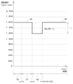
- FIGS 3 and 4 are diagrams showing a first and second example of the motor rotation speed R when auto idle control is performed, respectively.
- the first example shown in Figure 3 shows a state in which the operator operates the rotation speed operation device 36 to set the set rotation speed Rt to 2200 rpm/min. Also, in the first example shown in Figure 3, the operator operates the operation device 5 after the elapsed time t exceeds the second threshold value t2 (at the point of elapsed time t3 shown in Figure 3, t3>t2).
- the second period T2, third period T3, and fourth period T4 shown in FIG. 3 are periods during which the operator does not operate the operation device 5, and AI-SW 35b detects the OFF state.
- the operator operates the operation device 5 after the elapsed time t exceeds the second threshold value t2.
- the end of the fourth period T4 is the point at which the operator operates the operation device 5, and AI-SW 35b detects the ON state.
- the control device 30 When the control device 30 detects that the AI-SW 35b is in the OFF state, it determines that the operating device 5 is not being operated and that all of the work devices 20, 10 are in an inoperative state, and calculates the elapsed time t.
- the second period T2 is a period during which the elapsed time t exceeds zero and is less than the first threshold value t1 (0 ⁇ t ⁇ t1), and the control device 30 continues from the first period T1 to control the motor rotation speed R at the set rotation speed Rt (2200 rpm/min) operated by the rotation speed operating device 36.
- the third period T3 is a period during which the elapsed time t is equal to or greater than the first threshold value t1 and less than the second threshold value t2 (t1 ⁇ t ⁇ t2), and the control device 30 reduces the motor rotation speed R by a predetermined value r (500 rpm/min) from the set rotation speed Rt operated by the rotation speed operation device 36 to the reduced rotation speed Rp.
- the set rotation speed Rt is operated to 2200 rpm/min, so the control device 30 controls the motor rotation speed R to 1700 rpm/min.
- the fourth period T4 is the period from when the elapsed time t reaches the second threshold value t2 until the operator operates the operating device 5 (t2 ⁇ t ⁇ t3). During the fourth period T4, the control device 30 reduces the motor rotation speed R to the idling rotation speed Ri (250 rpm/min).
- the control device 30 detects that the AI-SW 35b is in the ON state. Therefore, the control device 30 determines that the operating device 5 has been operated and that one of the work devices 20, 10 is in the operating state. Therefore, the control device 30 resets the calculated elapsed time t and controls the motor rotation speed R at the set rotation speed Rt (2200 rpm/min) immediately before the elapsed time t becomes the first threshold value t1 (fifth period T5).
- the control device 30 increases the motor rotation speed R by 1950 rpm/min from the idling rotation speed Ri (250 rpm/min) to which the motor rotation speed R was reduced in the fifth period T5 to the set rotation speed Rt (2200 rpm/min).
- the second example shown in FIG. 4 shows a state in which the operator operates the rotation speed operating device 36 to set the set rotation speed Rt to 1600 rpm/min. Also, in the second example shown in FIG. 4, the operator operates the operating device 5 when the elapsed time t exceeds the first threshold value t1 and before it reaches the second threshold value t2 (at the point of time of elapsed time t4 shown in FIG. 4, t1 ⁇ t4 ⁇ t2).
- the control device 30 controls the motor rotation speed R at the set rotation speed Rt operated by the rotation speed operating device 36.
- the seventh period T7 and eighth period T8 shown in FIG. 4 are periods during which the operator does not operate the operating device 5, and the AI-SW 35b detects the off state.
- the seventh period T7 is a period during which the elapsed time t exceeds zero and is less than the first threshold value t1 (0 ⁇ t ⁇ t1), and the control device 30 continues from the sixth period T6 to control the motor rotation speed R at the set rotation speed Rt (1600 rpm/min) operated by the rotation speed operation device 36.
- the seventh period T7 is a period during which the elapsed time t is equal to or greater than the first threshold value t1, until the operator operates the operating device 5 (t1 ⁇ t ⁇ t4).
- the control device 30 reduces the motor rotation speed R from the set rotation speed Rt operated by the rotation speed operation device 36 by a predetermined value r (500 rpm/min) to control it to a reduced rotation speed Rp.
- the set rotation speed Rt is set to 1600 rpm/min, so the control device 30 controls the motor rotation speed R to 1100 rpm/min.
- the control device 30 detects that the AI-SW 35b is in the ON state, resets the calculated elapsed time t, and controls the motor rotation speed R at the set rotation speed Rt immediately before the elapsed time t becomes the first threshold value t1 (eighth period T8). That is, when transitioning from the seventh period T7 to the eighth period T8, the control device 30 increases the motor rotation speed R by a predetermined value r (500 rpm/min) from 1100 rpm/min, which was reduced in the seventh period T7, to the set rotation speed Rt.
- r 500 rpm/min
- the control device 30 reduces the motor rotation speed R to the idling rotation speed Ri twice: once when the elapsed time t reaches the first threshold value t1, and once when it reaches the second threshold value t2. In other words, the control device 30 reduces the motor rotation speed R to the idling rotation speed Ri in two stages according to the elapsed time t.
- the control device 30 reduces the motor rotation speed R to the idling rotation speed Ri, thereby saving energy in the work machine 1. Furthermore, not only is energy saved by temporarily reducing the motor rotation speed R before the elapsed time t exceeds the first threshold value t1 and reaches the second threshold value t2, but when the operating device 5 is operated before the elapsed time t reaches the second threshold value t2, the control device 30 can increase the motor rotation speed R by a predetermined value r to return to the original work, thereby achieving both responsiveness and energy saving in the work machine 1.
- the motor rotation speed R may be controlled to decrease from the set rotation speed Rt to the idling rotation speed Ri, without dividing the motor rotation speed R into multiple stages.
- the control device 30 controls the electric motor 46 to a stop rotation speed R0 (for example, a very small rotation speed R such as 0 rpm/min or less than 1 rpm/min) that corresponds to the stopped state of the electric motor 46, regardless of the operation of the rotation speed control device 36 or idling control.
- the control device 30 sends an instruction signal to the inverter 45 based on the calculated actual motor rotation speed Ra, and reduces the rotation speed R of the electric motor 46 to the stop rotation speed R0.
- the control device 30 may control the electric motor 46 to the idling rotation speed Ri when the unload lever 37 is swung upward and the unload lever 37 is in the second position while the electric motor 46 is being driven. In this case, when a predetermined time has elapsed since the unload lever 37 was swung upward, the control device 30 may control the electric motor 46 from the idling rotation speed Ri to the stop rotation speed R0.
- FIG. 5 is a diagram for explaining a series of steps in the control of the motor rotation speed R by the control device 30.
- the series of processes shown in FIG. 5 are executed by the CPU based on a software program previously stored in the memory of the control device 30.
- FIG. 5 also shows a state in which the electric motor 46 is being driven, i.e., a state in which the starter switch 32 is turned on.
- the control device 30 starts the electric motor 46 by the inverter 45. While the electric motor 46 is being driven, the control device 30 judges whether the unload lever 37 is in the first position (S1).
- control device 30 When the control device 30 detects that the AI-SW 35b is in the OFF state and determines that all of the working devices 20, 10 are in an inoperative state (S3, No), it determines whether the elapsed time t stored in memory is zero (S4). When the control device 30 determines that the elapsed time t stored in memory is zero (S4, Yes), it starts calculating the elapsed time t (S5) and proceeds to the processing of S1.
- control device 30 determines whether the elapsed time t is equal to or greater than the first threshold value t1 (S6, Yes), it determines whether the elapsed time t is equal to or greater than the second threshold value t2 (S7). If the control device 30 determines that the elapsed time t is less than the second threshold value t2 (S7, No), it sends an instruction signal to the inverter 45, reduces the motor rotation speed R to a reduced rotation speed Rp obtained by subtracting a predetermined value r from the set rotation speed Rt (S8, first step), and proceeds to processing in S1.
- control device 30 determines that the elapsed time t is equal to or greater than the second threshold value t2 (S7, Yes), it sends an instruction signal to the inverter 45 to reduce the motor rotation speed R from the deceleration rotation speed Rp to the idling rotation speed Ri (S9, second step), and proceeds to processing in S1.
- the rotation speed detection device 35a may detect the actual rotation speed Ra of the engine, and the actual rotation speed Ra immediately before the elapsed time t reaches the first threshold value t1 may be reduced by a predetermined value.
- the work machine 1 described in item 1 or 2 is provided with a rotation speed operating device 36 for operating the set rotation speed Rt, and the control device 30 controls the rotation speed R of the rotation drive source 46 at the set rotation speed Rt operated by the rotation speed operating device 36 when the elapsed time t is less than the first threshold value t1, and reduces the rotation speed R of the rotation drive source 46 from the set rotation speed Rt to the reduced rotation speed Rp when the elapsed time t becomes the first threshold value t1.
- the rotation speed R of the rotation drive source 46 is reduced from the rotation speed Rt controlled by the rotation speed control device 36, so that the consumption of the energy source caused by driving the rotation drive source 46 can be reduced without operating the rotation speed control device 36.
- the work machine 1 described in item 1 or 2 is equipped with a rotation speed detection device 35a that detects the rotation speed R of the rotation drive source 46, and the control device 30 reduces the rotation speed R of the rotation drive source 46 from the rotation speed R of the rotation drive source 46 just before the elapsed time t detected by the rotation speed detection device 35a becomes the first threshold value t1 to the reduced rotation speed Rp when the elapsed time t becomes the first threshold value t1.
- the control device 30 reduces the rotation speed R of the rotation drive source 46 to the reduced rotation speed Rp when the elapsed time t reaches the first threshold value t1, and then maintains the rotation speed R of the rotation drive source 46 at the reduced rotation speed Rp until the elapsed time t reaches a second threshold value t2 that is longer than the first threshold value t1, and when the elapsed time t reaches the second threshold value t2, further reduces the rotation speed R of the rotation drive source 46 from the reduced rotation speed Rp.
- the control device 30 when determining that the operating device 5 has been operated when the elapsed time t is equal to or greater than the first threshold value t1, controls the rotation speed R of the rotational drive source 46 at the set rotation speed Rt immediately before the elapsed time t becomes the first threshold value t1.
- the work machine 1 is described in item 2, or any one of items 3 to 7 which cite item 2.
- the working machine 1 according to item 9 has the above-mentioned configuration, which makes it possible to reduce the consumption of the energy source (electricity) by driving the electric motor, and to reduce the consumption of the energy source (fuel) by driving the engine.
- the rotation speed R of the rotation drive source 46 is not reduced all at once to the idling rotation speed Ri, but is first reduced to the reduced rotation speed Rp and then further reduced to the idling rotation speed Ri. Therefore, when the elapsed time t exceeds the first threshold value t1 and the rotation speed R of the rotation drive source 46 is reduced to the idling rotation speed Ri, the consumption of the energy source by driving the rotation drive source 46 can be reduced, whereas when the elapsed time t is relatively short and the rotation speed R of the rotation drive source 46 has not yet been reduced to the idling rotation speed Ri, the rotation speed R of the rotation drive source 46 can be easily increased.
Landscapes
- Engineering & Computer Science (AREA)
- General Engineering & Computer Science (AREA)
- Mining & Mineral Resources (AREA)
- Structural Engineering (AREA)
- Civil Engineering (AREA)
- Physics & Mathematics (AREA)
- Mechanical Engineering (AREA)
- Chemical & Material Sciences (AREA)
- Fluid Mechanics (AREA)
- Analytical Chemistry (AREA)
- General Physics & Mathematics (AREA)
- Combustion & Propulsion (AREA)
- Operation Control Of Excavators (AREA)
- Control Of Positive-Displacement Pumps (AREA)
Priority Applications (3)
| Application Number | Priority Date | Filing Date | Title |
|---|---|---|---|
| EP23911420.0A EP4644614A1 (en) | 2022-12-28 | 2023-11-14 | Work machine and method for controlling work machine |
| JP2024567275A JPWO2024142637A1 (https=) | 2022-12-28 | 2023-11-14 | |
| US19/220,423 US20250283303A1 (en) | 2022-12-28 | 2025-05-28 | Working machine and method of controlling working machine |
Applications Claiming Priority (2)
| Application Number | Priority Date | Filing Date | Title |
|---|---|---|---|
| JP2022-211307 | 2022-12-28 | ||
| JP2022211307 | 2022-12-28 |
Related Child Applications (1)
| Application Number | Title | Priority Date | Filing Date |
|---|---|---|---|
| US19/220,423 Continuation US20250283303A1 (en) | 2022-12-28 | 2025-05-28 | Working machine and method of controlling working machine |
Publications (1)
| Publication Number | Publication Date |
|---|---|
| WO2024142637A1 true WO2024142637A1 (ja) | 2024-07-04 |
Family
ID=91716970
Family Applications (1)
| Application Number | Title | Priority Date | Filing Date |
|---|---|---|---|
| PCT/JP2023/040966 Ceased WO2024142637A1 (ja) | 2022-12-28 | 2023-11-14 | 作業機、及び作業機の制御方法 |
Country Status (4)
| Country | Link |
|---|---|
| US (1) | US20250283303A1 (https=) |
| EP (1) | EP4644614A1 (https=) |
| JP (1) | JPWO2024142637A1 (https=) |
| WO (1) | WO2024142637A1 (https=) |
Citations (4)
| Publication number | Priority date | Publication date | Assignee | Title |
|---|---|---|---|---|
| JP2012041716A (ja) * | 2010-08-18 | 2012-03-01 | Hitachi Constr Mach Co Ltd | 電動式建設機械 |
| WO2019179595A1 (en) * | 2018-03-19 | 2019-09-26 | Volvo Construction Equipment Ab | An electrically powered hydraulic system and a method for controlling an electrically powered hydraulic system |
| JP2021080707A (ja) | 2019-11-18 | 2021-05-27 | 株式会社クボタ | 作業機 |
| JP2021080709A (ja) * | 2019-11-18 | 2021-05-27 | 株式会社クボタ | 旋回作業機 |
-
2023
- 2023-11-14 WO PCT/JP2023/040966 patent/WO2024142637A1/ja not_active Ceased
- 2023-11-14 JP JP2024567275A patent/JPWO2024142637A1/ja active Pending
- 2023-11-14 EP EP23911420.0A patent/EP4644614A1/en active Pending
-
2025
- 2025-05-28 US US19/220,423 patent/US20250283303A1/en active Pending
Patent Citations (4)
| Publication number | Priority date | Publication date | Assignee | Title |
|---|---|---|---|---|
| JP2012041716A (ja) * | 2010-08-18 | 2012-03-01 | Hitachi Constr Mach Co Ltd | 電動式建設機械 |
| WO2019179595A1 (en) * | 2018-03-19 | 2019-09-26 | Volvo Construction Equipment Ab | An electrically powered hydraulic system and a method for controlling an electrically powered hydraulic system |
| JP2021080707A (ja) | 2019-11-18 | 2021-05-27 | 株式会社クボタ | 作業機 |
| JP2021080709A (ja) * | 2019-11-18 | 2021-05-27 | 株式会社クボタ | 旋回作業機 |
Non-Patent Citations (1)
| Title |
|---|
| See also references of EP4644614A1 |
Also Published As
| Publication number | Publication date |
|---|---|
| EP4644614A1 (en) | 2025-11-05 |
| US20250283303A1 (en) | 2025-09-11 |
| JPWO2024142637A1 (https=) | 2024-07-04 |
Similar Documents
| Publication | Publication Date | Title |
|---|---|---|
| US8424302B2 (en) | Control device of engine, control device of engine and hydraulic pump, and control device of engine, hydraulic pump, and generator motor | |
| CN100554667C (zh) | 液压工程机械的控制装置 | |
| CN101861455B (zh) | 发动机的控制装置 | |
| KR101652661B1 (ko) | 건설 기계 | |
| CN102124233B (zh) | 液压作业机械的发动机加载减速抑制装置 | |
| KR101834589B1 (ko) | 선회체를 갖는 건설 기계 | |
| CN103443363A (zh) | 混合动力式工程机械及用于该工程机械的辅助控制装置 | |
| JP7451789B2 (ja) | 作業機 | |
| KR20150097802A (ko) | 건설 기계 | |
| EP2518219B1 (en) | Device for driving/controlling ac motor | |
| CN101297106A (zh) | 发动机的控制装置、发动机及液压泵的控制装置、以及发动机、液压泵及发电电动机的控制装置 | |
| JP4538427B2 (ja) | 作業用車両 | |
| JP2004340259A (ja) | 建設機械の走行駆動装置 | |
| JP2006233843A (ja) | ハイブリッド駆動式のホイール系作業車両 | |
| WO2024142637A1 (ja) | 作業機、及び作業機の制御方法 | |
| JP2021067147A (ja) | 作業機 | |
| JP7399820B2 (ja) | 作業機 | |
| JP7146665B2 (ja) | 作業機 | |
| JP4330431B2 (ja) | 冷却ファン制御システム | |
| JP2007321463A (ja) | 作業用車両 | |
| JP7446768B2 (ja) | 作業機 | |
| WO2007139168A1 (ja) | 作業用車両 | |
| WO2024142562A1 (ja) | 電動作業機、及び電動作業機の制御方法 | |
| JP3564181B2 (ja) | 油圧モータの駆動制御装置 | |
| JP4073191B2 (ja) | 作業機 |
Legal Events
| Date | Code | Title | Description |
|---|---|---|---|
| 121 | Ep: the epo has been informed by wipo that ep was designated in this application |
Ref document number: 23911420 Country of ref document: EP Kind code of ref document: A1 |
|
| WWE | Wipo information: entry into national phase |
Ref document number: 2024567275 Country of ref document: JP |
|
| WWE | Wipo information: entry into national phase |
Ref document number: 2023911420 Country of ref document: EP |
|
| NENP | Non-entry into the national phase |
Ref country code: DE |
|
| ENP | Entry into the national phase |
Ref document number: 2023911420 Country of ref document: EP Effective date: 20250728 |
|
| ENP | Entry into the national phase |
Ref document number: 2023911420 Country of ref document: EP Effective date: 20250728 |
|
| WWP | Wipo information: published in national office |
Ref document number: 2023911420 Country of ref document: EP |